EP4329085A1 - Protection device for propulsion batteries against conductive energy discharge - Google Patents
Protection device for propulsion batteries against conductive energy discharge Download PDFInfo
- Publication number
- EP4329085A1 EP4329085A1 EP22192381.6A EP22192381A EP4329085A1 EP 4329085 A1 EP4329085 A1 EP 4329085A1 EP 22192381 A EP22192381 A EP 22192381A EP 4329085 A1 EP4329085 A1 EP 4329085A1
- Authority
- EP
- European Patent Office
- Prior art keywords
- battery
- protection device
- propulsion
- battery cell
- conductive element
- Prior art date
- Legal status (The legal status is an assumption and is not a legal conclusion. Google has not performed a legal analysis and makes no representation as to the accuracy of the status listed.)
- Withdrawn
Links
- 229910052751 metal Inorganic materials 0.000 claims abstract description 17
- 239000002184 metal Substances 0.000 claims abstract description 17
- 239000004020 conductor Substances 0.000 claims abstract description 8
- 239000004411 aluminium Substances 0.000 description 3
- 229910052782 aluminium Inorganic materials 0.000 description 3
- XAGFODPZIPBFFR-UHFFFAOYSA-N aluminium Chemical compound [Al] XAGFODPZIPBFFR-UHFFFAOYSA-N 0.000 description 3
- 239000003990 capacitor Substances 0.000 description 3
- 230000007797 corrosion Effects 0.000 description 3
- 238000005260 corrosion Methods 0.000 description 3
- 239000000243 solution Substances 0.000 description 3
- 208000027418 Wounds and injury Diseases 0.000 description 2
- 230000006378 damage Effects 0.000 description 2
- 230000000694 effects Effects 0.000 description 2
- 239000008151 electrolyte solution Substances 0.000 description 2
- 208000014674 injury Diseases 0.000 description 2
- 231100000518 lethal Toxicity 0.000 description 2
- 230000001665 lethal effect Effects 0.000 description 2
- 229910001416 lithium ion Inorganic materials 0.000 description 2
- 238000012423 maintenance Methods 0.000 description 2
- 241000282412 Homo Species 0.000 description 1
- 230000002411 adverse Effects 0.000 description 1
- 230000001419 dependent effect Effects 0.000 description 1
- 239000011810 insulating material Substances 0.000 description 1
- 238000009413 insulation Methods 0.000 description 1
- 239000000463 material Substances 0.000 description 1
- 230000035939 shock Effects 0.000 description 1
- 238000003466 welding Methods 0.000 description 1
Images



Classifications
-
- H—ELECTRICITY
- H01—ELECTRIC ELEMENTS
- H01M—PROCESSES OR MEANS, e.g. BATTERIES, FOR THE DIRECT CONVERSION OF CHEMICAL ENERGY INTO ELECTRICAL ENERGY
- H01M50/00—Constructional details or processes of manufacture of the non-active parts of electrochemical cells other than fuel cells, e.g. hybrid cells
- H01M50/50—Current conducting connections for cells or batteries
- H01M50/572—Means for preventing undesired use or discharge
-
- H—ELECTRICITY
- H01—ELECTRIC ELEMENTS
- H01M—PROCESSES OR MEANS, e.g. BATTERIES, FOR THE DIRECT CONVERSION OF CHEMICAL ENERGY INTO ELECTRICAL ENERGY
- H01M10/00—Secondary cells; Manufacture thereof
- H01M10/42—Methods or arrangements for servicing or maintenance of secondary cells or secondary half-cells
- H01M10/4207—Methods or arrangements for servicing or maintenance of secondary cells or secondary half-cells for several batteries or cells simultaneously or sequentially
-
- H—ELECTRICITY
- H01—ELECTRIC ELEMENTS
- H01M—PROCESSES OR MEANS, e.g. BATTERIES, FOR THE DIRECT CONVERSION OF CHEMICAL ENERGY INTO ELECTRICAL ENERGY
- H01M50/00—Constructional details or processes of manufacture of the non-active parts of electrochemical cells other than fuel cells, e.g. hybrid cells
- H01M50/10—Primary casings; Jackets or wrappings
- H01M50/116—Primary casings; Jackets or wrappings characterised by the material
- H01M50/117—Inorganic material
- H01M50/119—Metals
-
- H—ELECTRICITY
- H01—ELECTRIC ELEMENTS
- H01M—PROCESSES OR MEANS, e.g. BATTERIES, FOR THE DIRECT CONVERSION OF CHEMICAL ENERGY INTO ELECTRICAL ENERGY
- H01M50/00—Constructional details or processes of manufacture of the non-active parts of electrochemical cells other than fuel cells, e.g. hybrid cells
- H01M50/20—Mountings; Secondary casings or frames; Racks, modules or packs; Suspension devices; Shock absorbers; Transport or carrying devices; Holders
- H01M50/204—Racks, modules or packs for multiple batteries or multiple cells
-
- H—ELECTRICITY
- H01—ELECTRIC ELEMENTS
- H01M—PROCESSES OR MEANS, e.g. BATTERIES, FOR THE DIRECT CONVERSION OF CHEMICAL ENERGY INTO ELECTRICAL ENERGY
- H01M50/00—Constructional details or processes of manufacture of the non-active parts of electrochemical cells other than fuel cells, e.g. hybrid cells
- H01M50/20—Mountings; Secondary casings or frames; Racks, modules or packs; Suspension devices; Shock absorbers; Transport or carrying devices; Holders
- H01M50/218—Mountings; Secondary casings or frames; Racks, modules or packs; Suspension devices; Shock absorbers; Transport or carrying devices; Holders characterised by the material
- H01M50/22—Mountings; Secondary casings or frames; Racks, modules or packs; Suspension devices; Shock absorbers; Transport or carrying devices; Holders characterised by the material of the casings or racks
- H01M50/222—Inorganic material
- H01M50/224—Metals
-
- H—ELECTRICITY
- H01—ELECTRIC ELEMENTS
- H01M—PROCESSES OR MEANS, e.g. BATTERIES, FOR THE DIRECT CONVERSION OF CHEMICAL ENERGY INTO ELECTRICAL ENERGY
- H01M50/00—Constructional details or processes of manufacture of the non-active parts of electrochemical cells other than fuel cells, e.g. hybrid cells
- H01M50/20—Mountings; Secondary casings or frames; Racks, modules or packs; Suspension devices; Shock absorbers; Transport or carrying devices; Holders
- H01M50/249—Mountings; Secondary casings or frames; Racks, modules or packs; Suspension devices; Shock absorbers; Transport or carrying devices; Holders specially adapted for aircraft or vehicles, e.g. cars or trains
-
- H—ELECTRICITY
- H01—ELECTRIC ELEMENTS
- H01M—PROCESSES OR MEANS, e.g. BATTERIES, FOR THE DIRECT CONVERSION OF CHEMICAL ENERGY INTO ELECTRICAL ENERGY
- H01M50/00—Constructional details or processes of manufacture of the non-active parts of electrochemical cells other than fuel cells, e.g. hybrid cells
- H01M50/50—Current conducting connections for cells or batteries
- H01M50/571—Methods or arrangements for affording protection against corrosion; Selection of materials therefor
-
- H—ELECTRICITY
- H01—ELECTRIC ELEMENTS
- H01M—PROCESSES OR MEANS, e.g. BATTERIES, FOR THE DIRECT CONVERSION OF CHEMICAL ENERGY INTO ELECTRICAL ENERGY
- H01M2200/00—Safety devices for primary or secondary batteries
-
- H—ELECTRICITY
- H01—ELECTRIC ELEMENTS
- H01M—PROCESSES OR MEANS, e.g. BATTERIES, FOR THE DIRECT CONVERSION OF CHEMICAL ENERGY INTO ELECTRICAL ENERGY
- H01M2220/00—Batteries for particular applications
- H01M2220/20—Batteries in motive systems, e.g. vehicle, ship, plane
-
- Y—GENERAL TAGGING OF NEW TECHNOLOGICAL DEVELOPMENTS; GENERAL TAGGING OF CROSS-SECTIONAL TECHNOLOGIES SPANNING OVER SEVERAL SECTIONS OF THE IPC; TECHNICAL SUBJECTS COVERED BY FORMER USPC CROSS-REFERENCE ART COLLECTIONS [XRACs] AND DIGESTS
- Y02—TECHNOLOGIES OR APPLICATIONS FOR MITIGATION OR ADAPTATION AGAINST CLIMATE CHANGE
- Y02E—REDUCTION OF GREENHOUSE GAS [GHG] EMISSIONS, RELATED TO ENERGY GENERATION, TRANSMISSION OR DISTRIBUTION
- Y02E60/00—Enabling technologies; Technologies with a potential or indirect contribution to GHG emissions mitigation
- Y02E60/10—Energy storage using batteries
Definitions
- the present application relates to the build-up of stray capacitances in large propulsion battery systems for electrically driven vehicles.
- each module comprises a plurality of battery cells.
- Each cell is built up by an anode and a cathode separated by a separator an immersed in an electrolyte solution, that may be placed in a metal casing.
- the cells can be either prismatic or cylindrical.
- the cells are assembled or stacked in compartments, often called modules, to form battery units. These battery units are then often placed together in structures to form battery packs.
- Large vehicles requiring large amounts of energy often have several battery packs placed in different locations on the vehicle in order to distribute the weight and also be able to handle the battery packs during maintenance or replacement.
- the casing is often connected galvanically to the cathode of the cell. This is often done by welding the cathode to the aluminium casing, thereby providing a galvanic contact of very low ohm.
- the present application aims to reduce the risk of personal injuries as described above. This aim is solved by a protection device according to the independent patent claim. Preferable embodiments form the subject of the dependent patent claims.
- a protection device against electrical discharge through a human body may comprise a conductive element electrically connected between a cathode of a battery cell of a vehicle propulsion battery module and a metal casing surrounding the battery cell, which conductive element may display electrical resistive properties for limiting stray capacitance energy through a human body if a person comes in contact with a conductor of the battery cell.
- This solution will limit the discharge current caused by the stray capacitance between the cell casings and the surfaces of the modules, wherein released energy of the stray capacitance through a person coming in electrical contact with the battery system is reduced due to the division of voltage between the inner resistance of the person and the resistance of the conductive elements.
- the conductive element of the protection device may comprise an electrical resistor. Further, in relation to the inner resistance of a human, the conductive element may display an electrical resistance of at least 100 Ohm.
- a battery cell for a vehicle propulsion battery which battery cell may be provided with a metal casing and comprising a protection device as described above.
- a cathode of the battery cell may have a galvanic connection to the metal casing.
- a battery module comprising several battery cells, where at least a majority of the battery cells may be provided with a protection device as described above.
- the battery module may comprise a metal casing connectable to the ground of an electric vehicle.
- several such battery modules may be comprised in a propulsion battery system.
- the capacity of the propulsion battery system may be larger than 300 kWh, because larger propulsion battery systems increase the levels of discharge energy and therefore require protection devices as described above.
- Fig. 1 shows schematically a battery module 10 to be comprised in a battery system for propelling a vehicle, comprising a plurality of Li-Ion battery cells 12.
- Each cell 12 comprises a cathode plate 14 and an anode plate 16 with a separator sheet 18 between the cathode and the anode.
- the plates and sheet are placed in a metal casing 20, usually of aluminium, and the casing 20 is filled with an electrolyte solution.
- Separators 22 are also arranged between the plates 14, 16 and the casing 20.
- the casing 20 could be cylindrical or rectangular.
- the cathode plate 14 and the anode plate 16 are each provided with a tab or connection point for electrical connection with other cells for forming a battery module 10.
- a module 10 is often comprised of generally rectangular metal casing with a bottom 24 and sides 26. These surfaces are often separated by insulating material 28. The module is then closed by an upper cover (not shown). The metal casing of the module 10 is further electrically connected to the ground of the vehicle.
- a number of battery modules are then inter-connected electrically in parallel and series for forming propulsion battery packs for electrically driven vehicles.
- the total capacity of the battery packs of a battery system for a vehicle is often above 300 kWh and this means that several battery packs are installed in the vehicle.
- the cathode 14 of each cell is provided with a galvanic connection 30 to its casing 20, Fig. 1 , in order to obtain a galvanic contact with a very low ohm value.
- This low ohm contact gives rise to stray capacitance between the propulsion battery system and the earth of the vehicle.
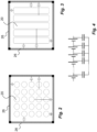
- the stray capacitance is formed between the cell casings 20 of the cells arranged in the module 10 and the surfaces 24, 26 of the modules, the bottom and sides, that function as plate capacitors, see Figs. 2 and 3 , showing cylindrical and prismatic cells.
- the stray capacitance value can be quite considerable, and can pose a serious risk of injury if a person comes in contact with a conductor of the propulsion battery system and a discharge of stray capacitance passes through the person's body.
- a protection device In order to reduce the risk of a discharge of stray capacitance through a human body in an above scenario, a protection device is provided. It comprises a conductive element 40 connected between the cathode of the battery cell and its metal casing as seen in Fig. 1 .
- the conductive element 40 is provided with an electrical resistance which limits the discharge current caused by the stray capacitance between the cell casings and the surfaces of the modules, wherein released energy of the stray capacitance through a person coming in electrical contact with the battery system is reduced due to the division of voltage between the inner resistance of the person (from about 500 ohm) and the resistance of the conductive elements.
- the conductive element 40 is provided with a resistance of generally 100 ohm or higher.
- the conductive element could be a resistor.
- all cells of a module may be provided with such a conductive element.
- the stray capacitance generated may not be so high that all cells in a module need to be provided with this conductive element. This will have to be assessed for each type and size of battery system and vehicle.
- Fig. 7 shows an example of an electrically driven vehicle 60, here an articulated commuter bus is shown.
- the bus is arranged with a propulsion battery system 62 comprising a number of battery packs 64, in turn comprising a number of battery modules 10 placed on different locations, both on the roof and adjacent an electric machine 66 for propelling the vehicle.
- This type of vehicle requires a large number of battery cells for providing the energy capacity needed.
- it is important to utilize the solution according the application for minimizing the effect of stray capacitance in order to greatly reduce the risk of serious adverse effects if a person comes in contact with a conductor of the battery system.
- insulation of the conductors of a battery system for vehicles is the main protection against electrical shocks and that the present application is an additional safety measure.
Landscapes
- Chemical & Material Sciences (AREA)
- Chemical Kinetics & Catalysis (AREA)
- Electrochemistry (AREA)
- General Chemical & Material Sciences (AREA)
- Engineering & Computer Science (AREA)
- Inorganic Chemistry (AREA)
- Secondary Cells (AREA)
- Manufacturing & Machinery (AREA)
- Aviation & Aerospace Engineering (AREA)
- Connection Of Batteries Or Terminals (AREA)
- Battery Mounting, Suspending (AREA)
- Electric Propulsion And Braking For Vehicles (AREA)
Abstract
Description
- The present application relates to the build-up of stray capacitances in large propulsion battery systems for electrically driven vehicles.
- When developing heavy electric vehicles such as trucks, lorries and busses, large battery systems are required for providing the necessary capacity and driving range between charging. These battery systems comprise battery packs with a number of battery modules, where each module comprises a plurality of battery cells. Each cell is built up by an anode and a cathode separated by a separator an immersed in an electrolyte solution, that may be placed in a metal casing. The cells can be either prismatic or cylindrical. The cells are assembled or stacked in compartments, often called modules, to form battery units. These battery units are then often placed together in structures to form battery packs. Large vehicles requiring large amounts of energy often have several battery packs placed in different locations on the vehicle in order to distribute the weight and also be able to handle the battery packs during maintenance or replacement.
- Since many of the battery cells have metal casings, often of aluminium, there is a risk of corrosion in the cell. In order to handle this, the casing is often connected galvanically to the cathode of the cell. This is often done by welding the cathode to the aluminium casing, thereby providing a galvanic contact of very low ohm.
- Even though the issue with corrosion is handled by this solution, the connection of low ohm results in that stray capacitances are built up between the vehicle propulsion electrical system and the ground of the vehicle, to which the metal casing of the battery modules or packs are connected. There is thus a risk of a discharge of the stray capacitance if a person comes in contact with a conductor of the electrical vehicle propulsion system.
- The danger with a discharge of the stray capacitance increases with the size of the battery system. This is because the stray capacitance is created between the surfaces between the earth of the chassis, i.e. the casings of the modules and the casing of the cells, forming a plurality of plate capacitors and since the large battery systems comprise a very large number of cells, the stray capacitance can be quite significant. This can be understood by the equation of the capacitance for a plate capacitor:

- With large battery systems, there is a risk that the discharge of stray capacitance can reach levels that can be lethal to humans, if the discharge passes a human body that comes in contact with a conductor. There is further a desire to increase the operating voltage of the battery systems, in particular with large capacity systems. However, an increase in the voltage leads to an increase in the discharge energy because the discharge energy is a function of U2, thus even further increasing the risk of lethal situations. This may in particular be the case during maintenance of the vehicle, removing or replacing battery modules. There is thus a challenge to balance the desire of compact battery systems with large capacity and higher voltages with the safety aspect regarding stray capacitance in those systems.
- The present application aims to reduce the risk of personal injuries as described above. This aim is solved by a protection device according to the independent patent claim. Preferable embodiments form the subject of the dependent patent claims.
- According to main aspect, a protection device against electrical discharge through a human body is provided, which protection device may comprise a conductive element electrically connected between a cathode of a battery cell of a vehicle propulsion battery module and a metal casing surrounding the battery cell, which conductive element may display electrical resistive properties for limiting stray capacitance energy through a human body if a person comes in contact with a conductor of the battery cell.
- This solution will limit the discharge current caused by the stray capacitance between the cell casings and the surfaces of the modules, wherein released energy of the stray capacitance through a person coming in electrical contact with the battery system is reduced due to the division of voltage between the inner resistance of the person and the resistance of the conductive elements.
- The conductive element of the protection device may comprise an electrical resistor. Further, in relation to the inner resistance of a human, the conductive element may display an electrical resistance of at least 100 Ohm.
- According to a further aspect, a battery cell for a vehicle propulsion battery is provided, which battery cell may be provided with a metal casing and comprising a protection device as described above. In this regard, a cathode of the battery cell may have a galvanic connection to the metal casing.
- According to yet an aspect, a battery module comprising several battery cells is provided, where at least a majority of the battery cells may be provided with a protection device as described above. Further, the battery module may comprise a metal casing connectable to the ground of an electric vehicle. Preferably, several such battery modules may be comprised in a propulsion battery system. In this regard, the capacity of the propulsion battery system may be larger than 300 kWh, because larger propulsion battery systems increase the levels of discharge energy and therefore require protection devices as described above.
- These and other aspects of, and advantages with, the present invention will become apparent from the following detailed description of the invention and from the accompanying drawings.
- In the following detailed description of the invention, reference will be made to the accompanying drawings, of which
-
Fig. 1 is a schematic cross-sectional side view of a propulsion battery module; -
Figs. 2-3 are schematic views from above of the propulsion battery module ofFig. 1 , -
Fig. 4 is a schematic view of addition of stray capacitance in a propulsion battery module ofFig. 1 , -
Fig. 5 is a view of the module provided with a protection device according to the present application, -
Fig. 6 is a view corresponding toFig. 4 with the protection device according to the application, and -
Fig. 7 is a schematic side view of an electrical vehicle that may be provided with the protection device according to the application. -
Fig. 1 shows schematically abattery module 10 to be comprised in a battery system for propelling a vehicle, comprising a plurality of Li-Ion battery cells 12. Eachcell 12 comprises acathode plate 14 and ananode plate 16 with aseparator sheet 18 between the cathode and the anode. The plates and sheet are placed in ametal casing 20, usually of aluminium, and thecasing 20 is filled with an electrolyte solution.Separators 22 are also arranged between theplates casing 20. Thecasing 20 could be cylindrical or rectangular. Thecathode plate 14 and theanode plate 16 are each provided with a tab or connection point for electrical connection with other cells for forming abattery module 10. Amodule 10 is often comprised of generally rectangular metal casing with a bottom 24 and sides 26. These surfaces are often separated by insulatingmaterial 28. The module is then closed by an upper cover (not shown). The metal casing of themodule 10 is further electrically connected to the ground of the vehicle. - A number of battery modules are then inter-connected electrically in parallel and series for forming propulsion battery packs for electrically driven vehicles. For large and heavy vehicles, the total capacity of the battery packs of a battery system for a vehicle is often above 300 kWh and this means that several battery packs are installed in the vehicle.
- In order to prevent galvanic corrosion in the Li-
Ion cells 12, thecathode 14 of each cell is provided with agalvanic connection 30 to itscasing 20,Fig. 1 , in order to obtain a galvanic contact with a very low ohm value. This low ohm contact gives rise to stray capacitance between the propulsion battery system and the earth of the vehicle. The stray capacitance is formed between thecell casings 20 of the cells arranged in themodule 10 and thesurfaces Figs. 2 and 3 , showing cylindrical and prismatic cells. According to Thevenin's theorem, the capacitance influence from all surfaces are added regardless if they have different potential from the battery cells. Hence, each and all of the surfaces of the cell casings will interact with the surfaces of the module, creating stray capacitances that are added, as seen inFig. 4 . - For large battery systems as mentioned above, with large areas from the casings of the plurality of modules, the stray capacitance value can be quite considerable, and can pose a serious risk of injury if a person comes in contact with a conductor of the propulsion battery system and a discharge of stray capacitance passes through the person's body.
- In order to reduce the risk of a discharge of stray capacitance through a human body in an above scenario, a protection device is provided. It comprises a
conductive element 40 connected between the cathode of the battery cell and its metal casing as seen inFig. 1 . Theconductive element 40 is provided with an electrical resistance which limits the discharge current caused by the stray capacitance between the cell casings and the surfaces of the modules, wherein released energy of the stray capacitance through a person coming in electrical contact with the battery system is reduced due to the division of voltage between the inner resistance of the person (from about 500 ohm) and the resistance of the conductive elements. Preferably, theconductive element 40 is provided with a resistance of generally 100 ohm or higher. The conductive element could be a resistor. - As a high safety measure, all cells of a module may be provided with such a conductive element. However, depending on the size of the modules and the number of modules, the stray capacitance generated may not be so high that all cells in a module need to be provided with this conductive element. This will have to be assessed for each type and size of battery system and vehicle.
-
Fig. 7 shows an example of an electrically drivenvehicle 60, here an articulated commuter bus is shown. As seen, the bus is arranged with apropulsion battery system 62 comprising a number of battery packs 64, in turn comprising a number ofbattery modules 10 placed on different locations, both on the roof and adjacent anelectric machine 66 for propelling the vehicle. This type of vehicle requires a large number of battery cells for providing the energy capacity needed. In this context, it is important to utilize the solution according the application for minimizing the effect of stray capacitance in order to greatly reduce the risk of serious adverse effects if a person comes in contact with a conductor of the battery system. It is however to be understood that insulation of the conductors of a battery system for vehicles is the main protection against electrical shocks and that the present application is an additional safety measure. - It is to be understood that the embodiment described above and shown in the drawing is to be regarded only as a non-limiting example and that the present application can be modified in many ways within the scope of the patent claims.
Claims (10)
- Protection device against electrical discharge through a human body, which protection device comprises a conductive element (40) electrically connected between a cathode (14) of a battery cell (12) of a vehicle propulsion battery module (10) and a metal casing (20) surrounding said battery cell (12), which conductive element (40) displays electrical resistive properties for limiting stray capacitance energy through a human body if a person comes in contact with a conductor of the battery cell (12).
- Protection device according to claim 1, wherein the conductive element (40) comprises an electrical resistor.
- Protection device according to claim 1 or 2, wherein said conductive element (40) displays an electrical resistance of at least 100 Ohm.
- Battery cell for a vehicle propulsion battery, which battery cell is provided with a metal casing (20) and comprising a protection device according to claims 1 - 3.
- Battery cell according to claim 4, wherein a cathode (14) of the battery cell (12) has a galvanic connection (30) to said metal casing (20).
- Battery module (10) comprising several battery cells (12), where at least a majority of the battery cells (12) are provided with a protection device according to claims 1-5.
- Battery module (10) according to claim 6, comprising a metal casing (24, 26) connectable to the ground of an electric vehicle.
- Propulsion battery system (62) comprising several battery modules (10) according to claims 6-7.
- Propulsion battery system (62) according to claim 8, wherein the capacity of the propulsion battery system (62) is larger than 300 kWh.
- Vehicle (60) comprising a propulsion battery system (62) according to claim 8 or 9.
Priority Applications (4)
| Application Number | Priority Date | Filing Date | Title |
|---|---|---|---|
| EP22192381.6A EP4329085A1 (en) | 2022-08-26 | 2022-08-26 | Protection device for propulsion batteries against conductive energy discharge |
| EP23758429.7A EP4578066A1 (en) | 2022-08-26 | 2023-08-22 | Protection device for propulsion batteries against conductive energy discharge |
| PCT/SE2023/050851 WO2024043822A1 (en) | 2022-08-26 | 2023-08-22 | Protection device for propulsion batteries against conductive energy discharge |
| CN202380055943.1A CN119605030A (en) | 2022-08-26 | 2023-08-22 | Protection device for propulsion batteries against the release of conducted energy |
Applications Claiming Priority (1)
| Application Number | Priority Date | Filing Date | Title |
|---|---|---|---|
| EP22192381.6A EP4329085A1 (en) | 2022-08-26 | 2022-08-26 | Protection device for propulsion batteries against conductive energy discharge |
Publications (1)
| Publication Number | Publication Date |
|---|---|
| EP4329085A1 true EP4329085A1 (en) | 2024-02-28 |
Family
ID=83081634
Family Applications (2)
| Application Number | Title | Priority Date | Filing Date |
|---|---|---|---|
| EP22192381.6A Withdrawn EP4329085A1 (en) | 2022-08-26 | 2022-08-26 | Protection device for propulsion batteries against conductive energy discharge |
| EP23758429.7A Pending EP4578066A1 (en) | 2022-08-26 | 2023-08-22 | Protection device for propulsion batteries against conductive energy discharge |
Family Applications After (1)
| Application Number | Title | Priority Date | Filing Date |
|---|---|---|---|
| EP23758429.7A Pending EP4578066A1 (en) | 2022-08-26 | 2023-08-22 | Protection device for propulsion batteries against conductive energy discharge |
Country Status (3)
| Country | Link |
|---|---|
| EP (2) | EP4329085A1 (en) |
| CN (1) | CN119605030A (en) |
| WO (1) | WO2024043822A1 (en) |
Citations (3)
| Publication number | Priority date | Publication date | Assignee | Title |
|---|---|---|---|---|
| US6117584A (en) * | 1997-07-25 | 2000-09-12 | 3M Innovative Properties Company | Thermal conductor for high-energy electrochemical cells |
| US10686178B1 (en) * | 2016-09-22 | 2020-06-16 | Apple Inc. | Battery cell interconnect and methods of manufacture thereof |
| CN113764834A (en) * | 2021-09-23 | 2021-12-07 | 中航锂电科技有限公司 | Battery and battery pack |
-
2022
- 2022-08-26 EP EP22192381.6A patent/EP4329085A1/en not_active Withdrawn
-
2023
- 2023-08-22 EP EP23758429.7A patent/EP4578066A1/en active Pending
- 2023-08-22 WO PCT/SE2023/050851 patent/WO2024043822A1/en not_active Ceased
- 2023-08-22 CN CN202380055943.1A patent/CN119605030A/en active Pending
Patent Citations (3)
| Publication number | Priority date | Publication date | Assignee | Title |
|---|---|---|---|---|
| US6117584A (en) * | 1997-07-25 | 2000-09-12 | 3M Innovative Properties Company | Thermal conductor for high-energy electrochemical cells |
| US10686178B1 (en) * | 2016-09-22 | 2020-06-16 | Apple Inc. | Battery cell interconnect and methods of manufacture thereof |
| CN113764834A (en) * | 2021-09-23 | 2021-12-07 | 中航锂电科技有限公司 | Battery and battery pack |
Also Published As
| Publication number | Publication date |
|---|---|
| CN119605030A (en) | 2025-03-11 |
| WO2024043822A1 (en) | 2024-02-29 |
| EP4578066A1 (en) | 2025-07-02 |
Similar Documents
| Publication | Publication Date | Title |
|---|---|---|
| US7479346B1 (en) | Battery pack | |
| EP2482367B1 (en) | Battery pack | |
| EP3346517B1 (en) | Battery system | |
| KR20120125461A (en) | Frame for an electrochemical energy storage device | |
| JP6988393B2 (en) | Battery module and battery pack | |
| EP2333872A1 (en) | Large capacity battery pack | |
| KR102352625B1 (en) | Battery Pack using battery module with short-circuit protection structure | |
| WO2014032768A9 (en) | Electrochemical energy storage cell and electrochemical energy storage device comprising at least one electrochemical energy storage cell of said type | |
| JP2817030B2 (en) | Electrochemical storage battery | |
| EP3446352B1 (en) | Electrochemical cell including electrode isolation frame | |
| US20130344361A1 (en) | Energy Store Unit Having Two Separate Electrochemical Areas | |
| KR20210104491A (en) | Battery module, battery pack and vehicle comprising the battery module | |
| CN115871516B (en) | Moving body | |
| US20130209845A1 (en) | Electrochemical cell having at least one pressure relief means | |
| EP4578066A1 (en) | Protection device for propulsion batteries against conductive energy discharge | |
| EP4625610A1 (en) | Battery module | |
| KR20230111655A (en) | Battery disconnect unit, battery system and operating method thereof | |
| EP3358644B1 (en) | Battery cell and battery module | |
| EP4607668A1 (en) | Battery cells and battery modules | |
| EP3217455A1 (en) | Electrode assembly and battery cell | |
| EP4648182A1 (en) | Battery module | |
| EP4675841A1 (en) | Power supply device and maintenance method therefor | |
| US20260112783A1 (en) | Prismatic cell | |
| US20240014450A1 (en) | Safety interconnect for a modular high-voltage battery system | |
| KR20260058466A (en) | Pack housing and battery pack including the same |
Legal Events
| Date | Code | Title | Description |
|---|---|---|---|
| PUAI | Public reference made under article 153(3) epc to a published international application that has entered the european phase |
Free format text: ORIGINAL CODE: 0009012 |
|
| STAA | Information on the status of an ep patent application or granted ep patent |
Free format text: STATUS: THE APPLICATION HAS BEEN PUBLISHED |
|
| AK | Designated contracting states |
Kind code of ref document: A1 Designated state(s): AL AT BE BG CH CY CZ DE DK EE ES FI FR GB GR HR HU IE IS IT LI LT LU LV MC MK MT NL NO PL PT RO RS SE SI SK SM TR |
|
| STAA | Information on the status of an ep patent application or granted ep patent |
Free format text: STATUS: REQUEST FOR EXAMINATION WAS MADE |
|
| 17P | Request for examination filed |
Effective date: 20240828 |
|
| RBV | Designated contracting states (corrected) |
Designated state(s): AL AT BE BG CH CY CZ DE DK EE ES FI FR GB GR HR HU IE IS IT LI LT LU LV MC MK MT NL NO PL PT RO RS SE SI SK SM TR |
|
| STAA | Information on the status of an ep patent application or granted ep patent |
Free format text: STATUS: THE APPLICATION IS DEEMED TO BE WITHDRAWN |
|
| 18D | Application deemed to be withdrawn |
Effective date: 20240829 |