EP4328564A1 - Thermogravimetric measurement apparatus and method for setting the same - Google Patents
Thermogravimetric measurement apparatus and method for setting the same Download PDFInfo
- Publication number
- EP4328564A1 EP4328564A1 EP23184234.5A EP23184234A EP4328564A1 EP 4328564 A1 EP4328564 A1 EP 4328564A1 EP 23184234 A EP23184234 A EP 23184234A EP 4328564 A1 EP4328564 A1 EP 4328564A1
- Authority
- EP
- European Patent Office
- Prior art keywords
- rotation speed
- cooling fan
- weight
- measurement
- sample
- Prior art date
- Legal status (The legal status is an assumption and is not a legal conclusion. Google has not performed a legal analysis and makes no representation as to the accuracy of the status listed.)
- Granted
Links
Images


Classifications
-
- G—PHYSICS
- G01—MEASURING; TESTING
- G01G—WEIGHING
- G01G1/00—Weighing apparatus involving the use of a counterweight or other counterbalancing mass
-
- G—PHYSICS
- G01—MEASURING; TESTING
- G01G—WEIGHING
- G01G1/00—Weighing apparatus involving the use of a counterweight or other counterbalancing mass
- G01G1/18—Balances involving the use of a pivoted beam, i.e. beam balances
-
- G—PHYSICS
- G01—MEASURING; TESTING
- G01G—WEIGHING
- G01G21/00—Details of weighing apparatus
-
- G—PHYSICS
- G01—MEASURING; TESTING
- G01G—WEIGHING
- G01G23/00—Auxiliary devices for weighing apparatus
-
- G—PHYSICS
- G01—MEASURING; TESTING
- G01N—INVESTIGATING OR ANALYSING MATERIALS BY DETERMINING THEIR CHEMICAL OR PHYSICAL PROPERTIES
- G01N1/00—Sampling; Preparing specimens for investigation
- G01N1/28—Preparing specimens for investigation including physical details of (bio-)chemical methods covered elsewhere, e.g. G01N33/50, C12Q
-
- G—PHYSICS
- G01—MEASURING; TESTING
- G01N—INVESTIGATING OR ANALYSING MATERIALS BY DETERMINING THEIR CHEMICAL OR PHYSICAL PROPERTIES
- G01N1/00—Sampling; Preparing specimens for investigation
- G01N1/28—Preparing specimens for investigation including physical details of (bio-)chemical methods covered elsewhere, e.g. G01N33/50, C12Q
- G01N1/44—Sample treatment involving radiation, e.g. heat
-
- G—PHYSICS
- G01—MEASURING; TESTING
- G01N—INVESTIGATING OR ANALYSING MATERIALS BY DETERMINING THEIR CHEMICAL OR PHYSICAL PROPERTIES
- G01N25/00—Investigating or analyzing materials by the use of thermal means
-
- G—PHYSICS
- G01—MEASURING; TESTING
- G01N—INVESTIGATING OR ANALYSING MATERIALS BY DETERMINING THEIR CHEMICAL OR PHYSICAL PROPERTIES
- G01N25/00—Investigating or analyzing materials by the use of thermal means
- G01N25/20—Investigating or analyzing materials by the use of thermal means by investigating the development of heat, i.e. calorimetry, e.g. by measuring specific heat, by measuring thermal conductivity
- G01N25/48—Investigating or analyzing materials by the use of thermal means by investigating the development of heat, i.e. calorimetry, e.g. by measuring specific heat, by measuring thermal conductivity on solution, sorption, or a chemical reaction not involving combustion or catalytic oxidation
- G01N25/4806—Details not adapted to a particular type of sample
- G01N25/4826—Details not adapted to a particular type of sample concerning the heating or cooling arrangements
-
- G—PHYSICS
- G01—MEASURING; TESTING
- G01N—INVESTIGATING OR ANALYSING MATERIALS BY DETERMINING THEIR CHEMICAL OR PHYSICAL PROPERTIES
- G01N5/00—Analysing materials by weighing, e.g. weighing small particles separated from a gas or liquid
-
- G—PHYSICS
- G01—MEASURING; TESTING
- G01N—INVESTIGATING OR ANALYSING MATERIALS BY DETERMINING THEIR CHEMICAL OR PHYSICAL PROPERTIES
- G01N5/00—Analysing materials by weighing, e.g. weighing small particles separated from a gas or liquid
- G01N5/04—Analysing materials by weighing, e.g. weighing small particles separated from a gas or liquid by removing a component, e.g. by evaporation, and weighing the remainder
-
- H—ELECTRICITY
- H05—ELECTRIC TECHNIQUES NOT OTHERWISE PROVIDED FOR
- H05K—PRINTED CIRCUITS; CASINGS OR CONSTRUCTIONAL DETAILS OF ELECTRIC APPARATUS; MANUFACTURE OF ASSEMBLAGES OF ELECTRICAL COMPONENTS
- H05K7/00—Constructional details common to different types of electric apparatus
- H05K7/20—Modifications to facilitate cooling, ventilating, or heating
-
- H—ELECTRICITY
- H05—ELECTRIC TECHNIQUES NOT OTHERWISE PROVIDED FOR
- H05K—PRINTED CIRCUITS; CASINGS OR CONSTRUCTIONAL DETAILS OF ELECTRIC APPARATUS; MANUFACTURE OF ASSEMBLAGES OF ELECTRICAL COMPONENTS
- H05K7/00—Constructional details common to different types of electric apparatus
- H05K7/20—Modifications to facilitate cooling, ventilating, or heating
- H05K7/20009—Modifications to facilitate cooling, ventilating, or heating using a gaseous coolant in electronic enclosures
- H05K7/20136—Forced ventilation, e.g. by fans
Definitions
- the present invention relates to a thermogravimetric measurement apparatus and a method for setting the same.
- JP2021-32624A discloses a thermogravimetric measurement apparatus that includes a sample plate on which a sample is to be placed, a balance connected to the sample plate, a heating unit adapted to heat the sample, and the like.
- This thermogravimetric measurement apparatus can measure changes in the weight of the sample placed on the sample plate while the sample is heated.
- thermogravimetric measurement apparatus includes a cooling fan to prevent the temperature of the apparatus body from increasing as the sample is heated.
- the cooling fan rotates and vibrates, the weight measurement value may be different from the actual weight of the sample. That is, in this case, the weight measurement value and the weight waveform, which is the continuous weight measurement value, may include noise.
- balances manufactured by the same method may still have mutually different natural frequencies.
- cooling fan cooling fans manufactured by the same method may still have mutually different vibration frequencies caused by rotation of a predetermined rotation speed.
- the amount of noise in the weight measurement value may vary from apparatus to apparatus even when the cooling fans are operated under the same conditions.
- thermogravimetric measurement apparatus As described above, it is difficult to adjust the amount of noise in the weight measurement value caused by the rotation and vibration of the cooling fan in the thermogravimetric measurement apparatus as described above.
- thermogravimetric measurement apparatus and a method for setting the same that allow for appropriate determination of the rotation speed in operation of a cooling fan for the individual apparatus.
- a first aspect of the invention is a method for setting a thermogravimetric measurement apparatus including a measurement unit adapted to measure a weight of a sample, a heating unit adapted to heat the sample, and a cooling fan physically connected to the measurement unit, and includes a rotation speed determination step.
- the rotation speed determination step monitors changes in a weight measurement value at the measurement unit while altering a rotation speed of the cooling fan, and determines a rotation speed in operation of the cooling fan based on the changes in the weight measurement value.
- a second aspect of the invention is a thermogravimetric measurement apparatus that includes a measurement unit, a heating unit, a cooling fan, and a rotation speed determination process unit.
- the measurement unit measures the weight of the sample.
- the heating unit heats the sample.
- the cooling fan is physically connected to the measurement unit.
- the rotation speed determination process unit monitors changes in a weight measurement value at the measurement unit while altering a rotation speed of the cooling fan, and determines a rotation speed in operation of the cooling fan based on the changes in the weight measurement value.
- the rotation speed in operation of the cooling fan is appropriately determined for the individual apparatus after identifying the relationship between the rotation speed of the cooling fan and the amount of noise caused in the weight measurement value due to the vibration of the cooling fan.
- the rotation speed in operation of the cooling fan is appropriately determined for the individual apparatus after identifying the relationship between the rotation speed of the cooling fan and the amount of noise caused in the weight measurement value due to the vibration of the cooling fan.
- FIG. 1 is a schematic cross-sectional view showing an example of the configuration of a thermogravimetric measurement apparatus 10 of the present embodiment.
- the thermogravimetric measurement apparatus 10 is an apparatus for measuring changes in the weight of a sample S that occur when the sample S is heated, cooled, or maintained at a constant temperature, and is a concept that encompasses a simultaneous thermogravimetric/differential thermal analysis instrument.
- the thermogravimetric measurement apparatus 10 may include a measurement unit 14, a heating unit 16, a heat radiation portion 18, and cooling fans 20 which are housed inside a housing 12.
- the housing 12 has an exhaust port 13 for exhausting air in the housing 12.
- the measurement unit 14 measures the weight of the sample S.
- the measurement unit 14 is a top-loading thermobalance and thus includes a sample holder 14a and a support member 14b which supports the sample holder 14a.
- the measurement unit 14 can obtain weight measurement values. For example, when the sample S is set on the sample holder 14a as shown in FIG. 1 , a weight measurement value indicating the weight of the sample S can be obtained.
- the measurement unit 14 is directly or indirectly attached to the housing 12.
- the measurement unit 14 may be attached to the housing 12 through various members for fixing the measurement unit 14 to the housing 12.
- the heating unit 16 is an electrically controllable furnace and heats the sample S.
- the heating unit 16 is arranged above the measurement unit 14.
- the thermogravimetric measurement apparatus 10 also includes an electrically controllable first displacement mechanism (not shown) which displaces the heating unit 16.
- the heating unit 16 can be vertically displaced by this first displacement mechanism.
- the heating unit 16 when measuring changes in the weight of the sample S while heating the sample S, for example, the heating unit 16 is placed at a position at which the sample S is housed in the heating unit 16 as shown in FIG. 1 .
- the heating unit 16 is placed at a position at which the sample S is not housed in the heating unit 16, that is, at a position indicated by the broken line in FIG. 1 .
- the thermogravimetric measurement apparatus 10 includes a general-purpose temperature sensor (not shown), and the temperature of the heating unit 16 is controlled based on the temperature signal output from this temperature sensor.
- the thermogravimetric measurement apparatus 10 also includes an electrically controllable second displacement mechanism (not shown) which displaces a portion of the housing 12. For example, a portion of the housing 12 that is lateral to the sample holder 14a can be opened and closed, or is slidable.
- thermogravimetric measurement apparatus 10 when an operation reception unit (not shown) receives the first predetermined operation by the user, the first and second displacement mechanisms cooperate to allow the sample S to be set onto or removed from the sample holder 14a.
- the heat radiation portion 18 is a member that absorbs heat and dissipates heat into the air.
- the heat radiation portion 18 may be a general-purpose heat sink, for example.
- the heat radiation portion 18 is provided around the support member 14b and below the heating unit 16.
- the cooling fans 20 are electrically controllable axial fans. Each cooling fan 20 functions to cool the inside of the housing 12 or to cool components of the thermogravimetric measurement apparatus 10.
- each cooling fan 20 is directly or indirectly attached to the housing 12 in the same manner as the measurement unit 14. In other words, the cooling fan 20 is physically connected to the measurement unit 14.
- the cooling fans 20 include a first cooling fan 20a, a second cooling fan 20b, and a third cooling fan 20c.
- the first cooling fan 20a cools the inside of the housing 12 by discharging the heated air inside the housing 12 to the outside of the housing 12 through the exhaust port 13.
- the first cooling fan 20a is always in operation. Thus, while the weight of the sample S is measured, the first cooling fan 20a is in operation.
- the second cooling fan 20b cools the heating unit 16. The second cooling fan 20b is stopped while the sample S is heated and is operated as necessary when the sample S is not being heated.
- the third cooling fan 20c cools the heat radiation portion 18.
- the third cooling fan 20c is stopped while the sample S is set onto the sample holder 14a or removed from the sample holder 14a. Also, the third cooling fan 20c is in operation at least while the weight of the sample S is measured.
- the cooling fans 20 may include fans other than the first cooling fan 20a, the second cooling fan 20b, and the third cooling fan 20c.
- the cooling fans 20 may include a fan for introducing air into the housing 12 from the outside of the housing 12 through the inlet port.
- thermogravimetric measurement apparatus 10 can measure changes in the weight that occur while the sample S on the sample holder 14a is heated, cooled, or maintained at a constant temperature. It should be noted that the configuration of the thermogravimetric measurement apparatus 10 shown in FIG. 1 is merely an example.
- thermogravimetric measurement apparatus 10 components other than the measurement unit 14 may be provided outside the housing 12 as long as they can function as described above.
- the thermogravimetric measurement apparatus 10 of the present embodiment may have a configuration in which at least the measurement unit 14 is provided inside the housing 12.
- a cooling fan 20 may be physically connected to the measurement unit 14 without the housing 12 interposed therebetween. That is, the cooling fan 20 may be directly attached to the measurement unit 14 or may be attached to the measurement unit 14 through a certain member.
- the measurement unit 14 of the present embodiment may be a suspension thermobalance or a horizontal thermobalance.
- the displacement direction of the heating unit 16 is set in accordance with the method of thermobalance.
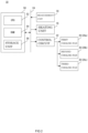
- FIG. 2 is a block diagram showing an example of the electrical configuration of the thermogravimetric measurement apparatus 10 of the present embodiment.
- the thermogravimetric measurement apparatus 10 includes a control circuit 22 and a control unit 50.
- the control unit 50, the measurement unit 14, the heating unit 16, the control circuit 22, and the like are electrically connected to one another via a circuit 24 such as a bus.
- the control circuit 22 is also electrically connected to the first cooling fan 20a, the second cooling fan 20b, and the third cooling fan 20c.
- the control circuit 22 is a circuit for controlling the operation of each cooling fan 20.
- the control circuit 22 adjusts the control conditions of the cooling fan 20, that is, the parameters that determine the rotation speed of the cooling fan 20 according to instructions from the control unit 50. For example, the control circuit 22 appropriately adjusts the voltage applied to the cooling fan 20 or the pulse signal transmitted to the cooling fan 20.
- the control unit 50 performs the overall control of the thermogravimetric measurement apparatus 10.
- the control unit 50 includes a central processing unit (CPU) 52.
- the control unit 50 also includes a random access memory (RAM) 54 and a storage unit 56, which can be directly accessed by the CPU 52.
- RAM random access memory
- the RAM 54 is used as a work area and a buffer area for the CPU 52.
- a non-volatile memory such as a hard disc drive (HDD) or a solid state drive (SSD) is used as the storage unit 56.
- the storage unit 56 stores a program (control program) for controlling the operation of the thermogravimetric measurement apparatus 10, data required for executing the control program (execution data), and the like.
- the storage unit 56 may also be configured to include the RAM 54.
- the measurement unit 14 and the cooling fans 20 are physically connected, and the vibration caused by the rotation of the cooling fans 20 thus propagates to the measurement unit 14. This may cause the weight measurement value to be different from the actual weight of the sample S. That is, the weight measurement value and the continuous weight measurement value (weight waveform) may include noise.
- measurement units that are manufactured by the same method may still be susceptible to mutually different vibration frequencies, that is, may have mutually different natural frequencies.
- cooling fans 20 cooling fans that are manufactured by the same method may still have mutually different vibration frequencies with respect to the rotation speed.
- the amount of noise in the weight measurement value may vary from apparatus to apparatus even when the cooling fans 20 are operated under the same conditions.
- the rotation speed of the cooling fan 20 with which the amount of noise in the weight measurement value is considered the smallest may vary from apparatus to apparatus.
- thermogravimetric measurement apparatus 10 it is difficult to adjust the amount of noise in the weight measurement value caused by the rotation and vibration of the cooling fans 20.
- thermogravimetric measurement apparatus 10 is configured to be capable of performing a rotation speed setting process at any given time.
- the rotation speed setting process identifies the relationship between the rotation speed of the cooling fan 20 and the amount of noise in the weight measurement value caused by the vibration of the cooling fan 20 and then sets a rotation speed in operation of the cooling fan 20.
- the cooling fan 20 in operation refers to that the cooling fan 20 is in operation other than the rotation speed setting process.
- the rotation speed in operation of the cooling fan 20 includes, for example, the rotation speed of the cooling fan 20 in a situation in which the sample S on the sample holder 14a is heated, cooled, or maintained at a constant temperature while changes in the weight of the sample S are measured.
- determining the control conditions of the cooling fan 20 determines the rotation speed of the cooling fan 20.
- the rotation speed of the cooling fan 20 may also be considered as a control condition of the cooling fan 20.
- the rotation speed in operation of the cooling fan 20 may be considered as a control condition of the cooling fan 20 in operation.
- the parameter that determines the control conditions of the cooling fan 20 may be the voltage applied to the cooling fan 20 or the pulse signal transmitted to the cooling fan 20 as described above.
- the rotation speed setting process is automatically executed before the weight of the sample S is measured, for example when the power of the thermogravimetric measurement apparatus 10 is switched from off to on.
- the rotation speed setting process may also be performed when the thermogravimetric measurement apparatus 10 receives the second predetermined operation by the user at the above-mentioned operation reception unit.
- the rotation speed determination step is performed one or more times.
- the rotation speed determination step monitors changes in the weight measurement value at the measurement unit 14 while altering the rotation speed of a cooling fan 20, and determines the rotation speed in operation of the cooling fan 20 based on the changes in the weight measurement value.
- the beating caused by vibrations of the multiple cooling fans 20 can be ignored because the natural frequency of the measurement unit 14 does not change. Furthermore, when multiple cooling fans 20 are operated, it is difficult to identify the cooling fan 20 that affects the weight measurement value.
- the rotation speed determination step monitors changes in the weight measurement value at the measurement unit 14 while altering the rotation speed of one of the multiple cooling fans 20 with the other cooling fans 20 stopped. In this case, the rotation speed determination step is repeatedly performed while switching the target cooling fan 20.
- the present embodiment can also obtain a negative weight measurement value because the measurement unit 14 is a thermobalance. As such, the rotation speed determination step is performed in a state in which the sample S is not set on the sample holder 14a.
- the rotation speed determination step may also be performed with the sample S set on the sample holder 14a.
- the rotation speed determination step When the rotation speed determination step is performed in a state in which the sample S is not set on the sample holder 14a, the weight measurement value itself corresponds to the amount of noise. That is, in this case, the amount of noise in the weight measurement value can be easily identified.
- the rotation speed determination step is therefore preferably performed in a state in which the sample S is not set on the sample holder 14a.
- the rotation speed determination step alters the rotation speed of the cooling fan 20 in ascending order.
- the rotation speed determination step may alter the rotation speed of the cooling fan 20 in descending order. There is no limitation to the range of alteration of the rotation speed of the cooling fan 20 in the rotation speed determination step.
- FIG. 3 is a schematic diagram showing an example of a weight waveform in the rotation speed determination step of the present embodiment.
- each cooling fan 20 is an electrically controllable component, and a response time T1 is needed between when the cooling fan 20 is controlled to alter its rotation speed and when the rotation speed of the cooling fan 20 becomes stable.
- the response time T1 is needed between when the cooling fan 20 is controlled to alter its rotation speed and when a weight measurement value is obtained in a state in which the rotation speed of the cooling fan 20 is stable.
- the rotation speed determination step monitors changes in the weight measurement value at the measurement unit 14 while altering the rotation speed of the cooling fan 20 in a stepwise manner.
- the rotation speed of the cooling fan 20 is altered in a stepwise manner, the rotation speed of the cooling fan 20 is altered each time a rotation speed maintaining time T2 elapses.
- the rotation speed maintaining time T2 is preferably longer than the response time T1. For example, in the rotation speed determination step, the rotation speed of the cooling fan 20 is altered every minute.
- the rotation speed in operation of the cooling fan 20 is determined based on the magnitude of the weight measurement value in a reference period P2 within a period P1 in which the rotation speed of the cooling fan 20 is maintained (rotation speed maintaining period).
- the rotation speed maintaining period P1 is a period corresponding to a rotation speed maintaining time T2.
- the maximum of the reference period P2 is the same as the rotation speed maintaining period P1.
- the reference period P2 is preferably a period after the response time T1 in the rotation speed maintaining period P1 has elapsed, that is, a period after the rotation speed of the cooling fan 20 becomes stable.
- the rotation speed determination step refers to the magnitude of the weight measurement value in the reference period P2 for each rotation speed maintaining period P1, that is, for each rotation speed.
- the rotation speed determination step refers to a peak-to-peak value of the weight waveform within the reference period P2 for each rotation speed.
- the peak-to-peak value refers to the difference (divergence amount) between the maximum value and the minimum value of the weight waveform.
- the magnitude of the peak-to-peak value of the weight waveform is proportional to the amount of noise in the weight waveform.
- the step may refer to the peak-to-peak value of the weight waveform for each rotation speed, and determine, as the rotation speed in operation of the cooling fan 20, the rotation speed with which the amount of noise in the weight measurement value is considered the smallest.
- rotation speed R1 may be determined as the rotation speed in operation of the cooling fan 20.
- one of the rotation speeds with which the amounts of noise in the weight measurement values are less than or equal to the permissible amount may be determined as the rotation speed in operation of the cooling fan 20.
- the highest rotation speed of the rotation speeds with which the amounts of noise in the weight measurement values are less than or equal to the permissible amount may be determined as the rotation speed in operation of the cooling fan 20.
- the amplitude of the weight waveform is a weight measurement value indicating the weight of the sample S when the sample S is set on the sample holder 14a, and is 0 when the sample S is not set on the sample holder 14a.
- the rotation speed in operation of the cooling fan 20 may be determined based on the average value of the weight measurement values in the reference period P2 within the rotation speed maintaining period P1.
- the rotation speed determination step refers to the average value of the weight measurement values in the reference period P2 for each rotation speed maintaining period P1, that is, for each rotation speed.
- the rotation speed determination step refers to the average value of the weight waveform in the reference period P2 for each rotation speed.
- the difference between the average value of the weight waveform and the reference value B is proportional to the amount of noise in the weight waveform.
- the step may refer to the difference between the average value of the weight waveform for each rotation speed and the reference value B, and determine, as the rotation speed in operation of the cooling fan 20, the rotation speed with which the amount of noise in the weight measurement value is considered the smallest.
- any one of the rotation speeds with which the amounts of noise in the weight measurement values are within the permissible range may be determined as the rotation speed in operation of the cooling fan 20.
- the highest rotation speed of the rotation speeds with which the amounts of noise in the weight measurement values are less than or equal to the permissible amount may be determined as the rotation speed in operation of the cooling fan 20 in the same manner.
- the storage unit 56 stores rotation speed information indicating this rotation speed as data.
- each piece of rotation speed information includes identification information that enables the identification of the associated cooling fan 20.
- the second and third cooling fans 20b and 20c are stopped, and the rotation speed of the first cooling fan 20a is increased in a stepwise manner. While the rotation speed of the first cooling fan 20a is increased in a stepwise manner, changes in the weight measurement value at the measurement unit 14 are monitored.
- the magnitude or average value of the weight measurement values in the reference period P2 is referred to for each rotation speed.
- the rotation speed with which the amount of noise in the weight measurement value is considered the smallest is determined as the rotation speed in operation of the first cooling fan 20a, for example.
- the storage unit 56 stores rotation speed information indicating this rotation speed as data. Also, in this case, the rotation speed information includes identification information indicating that this rotation speed information is associated with the first cooling fan 20a.
- thermogravimetric measurement apparatus 10 of the present embodiment refers to the rotation speed information when a rotation speed setting process is not in progress.
- each cooling fan 20 rotates at the rotation speed determined in the rotation speed determination step, when the sample S is heated, cooled, or maintained at a constant temperature while changes in the weight of the sample S are measured.
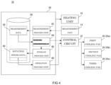
- FIG. 4 is a functional block diagram showing a specific example of the electrical configuration of the thermogravimetric measurement apparatus 10 of the present embodiment.
- illustration of the RAM 54 and the like is omitted.
- the storage unit 56 stores measurement data 58, rotation speed data 60, and the like.
- the measurement data 58 is data corresponding to weight measurement values.
- the measurement data 58 also corresponds to weight waveform.
- the rotation speed data 60 is rotation speed information in a data format.
- the storage unit 56 may store multiple pieces of rotation speed data 60.
- the rotation speed data 60 may include data format identification information. Although illustration is omitted, the storage unit 56 also stores the control program, execution data, and the like as described above.
- thermogravimetric measurement apparatus 10 may function as a measurement process unit 62, a rotation speed determination process unit 64, a storage process unit 66, and an operation process unit 68.
- the measurement process unit 62 causes the storage unit 56 to store the weight measurement values obtained by the measurement unit 14 as measurement data 58.
- the rotation speed determination process unit 64 functions to perform the rotation speed determination step. As such, the rotation speed determination process unit 64 monitors changes in the weight measurement value at the measurement unit 14 by referring to the measurement data 58 while altering the rotation speed of the cooling fan 20, and determines the rotation speed in operation of the cooling fan 20 based on the changes in the weight measurement value.
- the rotation speed determination process unit 64 monitors changes in the weight measurement value at the measurement unit 14 while altering the rotation speed of the cooling fan 20 in a stepwise manner.
- the rotation speed determination process unit 64 determines the rotation speed in operation of the cooling fan 20 based on the magnitude of the weight measurement values in the reference period P2 within the rotation speed maintaining period P1.
- the rotation speed determination process unit 64 may also determine the rotation speed in operation of the cooling fan 20 based on the average value of the weight measurement values in the reference period P2 within the rotation speed maintaining period P1.
- the storage process unit 66 causes the storage unit 56 to store the rotation speed determined by the rotation speed determination process unit 64 as rotation speed data 60.
- the operation process unit 68 refers to the rotation speed data 60 as necessary and rotates the cooling fan 20 at the rotation speed indicated by the rotation speed data 60.
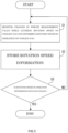
- FIG. 5 is a flowchart showing an example of rotation speed setting process of the thermogravimetric measurement apparatus 10 of the present embodiment.
- the rotation speed setting process may start at any given time as described above.
- Step S1 monitors changes in the weight measurement value at the measurement unit 14 while altering the rotation speed of a cooling fan 20 and determines the rotation speed in operation of the cooling fan 20 based on the changes in the weight measurement value.
- step S1 monitors changes in the weight measurement value at the measurement unit 14 while increasing or decreasing the rotation speed of one of the multiple cooling fans 20 in a stepwise manner with the other cooling fans 20 stopped, and determines the rotation speed in operation of the cooling fan 20 based on the magnitude or average value of the weight measurement values in the reference period P2 within the rotation speed maintaining period P1.
- Step S2 causes the storage unit 56 to store information on the rotation speed determined at step S1 as rotation speed information indicating the rotation speed in operation of the cooling fan 20.
- Step S3 determines whether the rotation speed in operation is determined for each of the cooling fans 20. If the answer at step S3 is "NO”, that is, if the rotation speed in operation is not determined for any of the cooling fans 20, the process returns to step S1 to determine the rotation speed in operation for another cooling fan 20. If the answer at step S3 is "YES”, that is, if the rotation speed in operation is determined for all the cooling fans 20, the rotation speed setting process ends.
- thermogravimetric measurement apparatus 10 may therefore be modified as appropriate within the range in which the effects of the invention can be obtained. Additionally, the order of the steps shown in the flowchart of the present embodiment may be modified as appropriate provided that the same result can be obtained.
Landscapes
- Physics & Mathematics (AREA)
- General Physics & Mathematics (AREA)
- Chemical & Material Sciences (AREA)
- Biochemistry (AREA)
- Health & Medical Sciences (AREA)
- Life Sciences & Earth Sciences (AREA)
- Analytical Chemistry (AREA)
- General Health & Medical Sciences (AREA)
- Immunology (AREA)
- Pathology (AREA)
- Engineering & Computer Science (AREA)
- Microelectronics & Electronic Packaging (AREA)
- Thermal Sciences (AREA)
- Chemical Kinetics & Catalysis (AREA)
- Combustion & Propulsion (AREA)
- Investigating Or Analyzing Materials Using Thermal Means (AREA)
Abstract
Description
- The present invention relates to a thermogravimetric measurement apparatus and a method for setting the same.
- For example,
JP2021-32624A - Such a thermogravimetric measurement apparatus includes a cooling fan to prevent the temperature of the apparatus body from increasing as the sample is heated. However, when the cooling fan rotates and vibrates, the weight measurement value may be different from the actual weight of the sample. That is, in this case, the weight measurement value and the weight waveform, which is the continuous weight measurement value, may include noise.
- As for the balance, balances manufactured by the same method may still have mutually different natural frequencies. As for the cooling fan, cooling fans manufactured by the same method may still have mutually different vibration frequencies caused by rotation of a predetermined rotation speed. As such, with the thermogravimetric measurement apparatus, the amount of noise in the weight measurement value may vary from apparatus to apparatus even when the cooling fans are operated under the same conditions.
- For these reasons, it is difficult to adjust the amount of noise in the weight measurement value caused by the rotation and vibration of the cooling fan in the thermogravimetric measurement apparatus as described above.
- In view of the foregoing, it is an object of the present invention to provide a thermogravimetric measurement apparatus and a method for setting the same that allow for appropriate determination of the rotation speed in operation of a cooling fan for the individual apparatus.
- A first aspect of the invention is a method for setting a thermogravimetric measurement apparatus including a measurement unit adapted to measure a weight of a sample, a heating unit adapted to heat the sample, and a cooling fan physically connected to the measurement unit, and includes a rotation speed determination step. The rotation speed determination step monitors changes in a weight measurement value at the measurement unit while altering a rotation speed of the cooling fan, and determines a rotation speed in operation of the cooling fan based on the changes in the weight measurement value.
- A second aspect of the invention is a thermogravimetric measurement apparatus that includes a measurement unit, a heating unit, a cooling fan, and a rotation speed determination process unit. The measurement unit measures the weight of the sample. The heating unit heats the sample. The cooling fan is physically connected to the measurement unit. The rotation speed determination process unit monitors changes in a weight measurement value at the measurement unit while altering a rotation speed of the cooling fan, and determines a rotation speed in operation of the cooling fan based on the changes in the weight measurement value.
- According to the first aspect of the invention, the rotation speed in operation of the cooling fan is appropriately determined for the individual apparatus after identifying the relationship between the rotation speed of the cooling fan and the amount of noise caused in the weight measurement value due to the vibration of the cooling fan.
- According to the second aspect of the invention, the rotation speed in operation of the cooling fan is appropriately determined for the individual apparatus after identifying the relationship between the rotation speed of the cooling fan and the amount of noise caused in the weight measurement value due to the vibration of the cooling fan.
-
-
FIG. 1 is a schematic cross-sectional view showing an example of the configuration of a thermogravimetric measurement apparatus of an embodiment; -
FIG. 2 is a block diagram showing an example of the electrical configuration of the thermogravimetric measurement apparatus of the present embodiment; -
FIG. 3 is a schematic view showing an example of a weight waveform in a rotation speed determination step of the present embodiment; -
FIG. 4 is a functional block diagram showing a specific example of the electrical configuration of the thermogravimetric measurement apparatus of the present embodiment; and -
FIG. 5 is a flowchart showing an example of a setting process of the thermogravimetric measurement apparatus of the present embodiment. -
FIG. 1 is a schematic cross-sectional view showing an example of the configuration of athermogravimetric measurement apparatus 10 of the present embodiment. Thethermogravimetric measurement apparatus 10 is an apparatus for measuring changes in the weight of a sample S that occur when the sample S is heated, cooled, or maintained at a constant temperature, and is a concept that encompasses a simultaneous thermogravimetric/differential thermal analysis instrument. - The
thermogravimetric measurement apparatus 10 may include ameasurement unit 14, aheating unit 16, aheat radiation portion 18, andcooling fans 20 which are housed inside ahousing 12. Thehousing 12 has anexhaust port 13 for exhausting air in thehousing 12. - The
measurement unit 14 measures the weight of the sample S. Themeasurement unit 14 is a top-loading thermobalance and thus includes asample holder 14a and asupport member 14b which supports thesample holder 14a. Themeasurement unit 14 can obtain weight measurement values. For example, when the sample S is set on thesample holder 14a as shown inFIG. 1 , a weight measurement value indicating the weight of the sample S can be obtained. - The
measurement unit 14 is directly or indirectly attached to thehousing 12. For example, themeasurement unit 14 may be attached to thehousing 12 through various members for fixing themeasurement unit 14 to thehousing 12. - The
heating unit 16 is an electrically controllable furnace and heats the sample S. Theheating unit 16 is arranged above themeasurement unit 14. Thethermogravimetric measurement apparatus 10 also includes an electrically controllable first displacement mechanism (not shown) which displaces theheating unit 16. Theheating unit 16 can be vertically displaced by this first displacement mechanism. - In the present embodiment, when measuring changes in the weight of the sample S while heating the sample S, for example, the
heating unit 16 is placed at a position at which the sample S is housed in theheating unit 16 as shown inFIG. 1 . When the sample S is set onto thesample holder 14a and when the sample S is removed from thesample holder 14a, theheating unit 16 is placed at a position at which the sample S is not housed in theheating unit 16, that is, at a position indicated by the broken line inFIG. 1 . - The
thermogravimetric measurement apparatus 10 includes a general-purpose temperature sensor (not shown), and the temperature of theheating unit 16 is controlled based on the temperature signal output from this temperature sensor. - The
thermogravimetric measurement apparatus 10 also includes an electrically controllable second displacement mechanism (not shown) which displaces a portion of thehousing 12. For example, a portion of thehousing 12 that is lateral to thesample holder 14a can be opened and closed, or is slidable. - In the
thermogravimetric measurement apparatus 10, when an operation reception unit (not shown) receives the first predetermined operation by the user, the first and second displacement mechanisms cooperate to allow the sample S to be set onto or removed from thesample holder 14a. - The
heat radiation portion 18 is a member that absorbs heat and dissipates heat into the air. Theheat radiation portion 18 may be a general-purpose heat sink, for example. Theheat radiation portion 18 is provided around thesupport member 14b and below theheating unit 16. - The
cooling fans 20 are electrically controllable axial fans. Eachcooling fan 20 functions to cool the inside of thehousing 12 or to cool components of thethermogravimetric measurement apparatus 10. - Also, each
cooling fan 20 is directly or indirectly attached to thehousing 12 in the same manner as themeasurement unit 14. In other words, thecooling fan 20 is physically connected to themeasurement unit 14. - The
cooling fans 20 include afirst cooling fan 20a, asecond cooling fan 20b, and athird cooling fan 20c. - The
first cooling fan 20a cools the inside of thehousing 12 by discharging the heated air inside thehousing 12 to the outside of thehousing 12 through theexhaust port 13. Thefirst cooling fan 20a is always in operation. Thus, while the weight of the sample S is measured, thefirst cooling fan 20a is in operation. - The
second cooling fan 20b cools theheating unit 16. Thesecond cooling fan 20b is stopped while the sample S is heated and is operated as necessary when the sample S is not being heated. - The
third cooling fan 20c cools theheat radiation portion 18. Thethird cooling fan 20c is stopped while the sample S is set onto thesample holder 14a or removed from thesample holder 14a. Also, thethird cooling fan 20c is in operation at least while the weight of the sample S is measured. - The cooling
fans 20 may include fans other than thefirst cooling fan 20a, thesecond cooling fan 20b, and thethird cooling fan 20c. For example, when thehousing 12 has an inlet port, the coolingfans 20 may include a fan for introducing air into thehousing 12 from the outside of thehousing 12 through the inlet port. - The
thermogravimetric measurement apparatus 10 can measure changes in the weight that occur while the sample S on thesample holder 14a is heated, cooled, or maintained at a constant temperature. It should be noted that the configuration of thethermogravimetric measurement apparatus 10 shown inFIG. 1 is merely an example. - Regarding the
thermogravimetric measurement apparatus 10, components other than themeasurement unit 14 may be provided outside thehousing 12 as long as they can function as described above. In other words, thethermogravimetric measurement apparatus 10 of the present embodiment may have a configuration in which at least themeasurement unit 14 is provided inside thehousing 12. - Also, in the
thermogravimetric measurement apparatus 10 of the present embodiment, a coolingfan 20 may be physically connected to themeasurement unit 14 without thehousing 12 interposed therebetween. That is, the coolingfan 20 may be directly attached to themeasurement unit 14 or may be attached to themeasurement unit 14 through a certain member. - Furthermore, the
measurement unit 14 of the present embodiment may be a suspension thermobalance or a horizontal thermobalance. The displacement direction of theheating unit 16 is set in accordance with the method of thermobalance. -
FIG. 2 is a block diagram showing an example of the electrical configuration of thethermogravimetric measurement apparatus 10 of the present embodiment. In addition to themeasurement unit 14, for example, thethermogravimetric measurement apparatus 10 includes acontrol circuit 22 and acontrol unit 50. - The
control unit 50, themeasurement unit 14, theheating unit 16, thecontrol circuit 22, and the like are electrically connected to one another via acircuit 24 such as a bus. Thecontrol circuit 22 is also electrically connected to thefirst cooling fan 20a, thesecond cooling fan 20b, and thethird cooling fan 20c. - The
control circuit 22 is a circuit for controlling the operation of each coolingfan 20. Thecontrol circuit 22 adjusts the control conditions of the coolingfan 20, that is, the parameters that determine the rotation speed of the coolingfan 20 according to instructions from thecontrol unit 50. For example, thecontrol circuit 22 appropriately adjusts the voltage applied to the coolingfan 20 or the pulse signal transmitted to the coolingfan 20. - The
control unit 50 performs the overall control of thethermogravimetric measurement apparatus 10. Thecontrol unit 50 includes a central processing unit (CPU) 52. Thecontrol unit 50 also includes a random access memory (RAM) 54 and astorage unit 56, which can be directly accessed by theCPU 52. - The
RAM 54 is used as a work area and a buffer area for theCPU 52. A non-volatile memory such as a hard disc drive (HDD) or a solid state drive (SSD) is used as thestorage unit 56. - The
storage unit 56 stores a program (control program) for controlling the operation of thethermogravimetric measurement apparatus 10, data required for executing the control program (execution data), and the like. Thestorage unit 56 may also be configured to include theRAM 54. - In the
thermogravimetric measurement apparatus 10, themeasurement unit 14 and the coolingfans 20 are physically connected, and the vibration caused by the rotation of the coolingfans 20 thus propagates to themeasurement unit 14. This may cause the weight measurement value to be different from the actual weight of the sample S. That is, the weight measurement value and the continuous weight measurement value (weight waveform) may include noise. - As for the
measurement unit 14, measurement units that are manufactured by the same method may still be susceptible to mutually different vibration frequencies, that is, may have mutually different natural frequencies. As for the coolingfans 20, cooling fans that are manufactured by the same method may still have mutually different vibration frequencies with respect to the rotation speed. - As such, as for the
thermogravimetric measurement apparatus 10, the amount of noise in the weight measurement value may vary from apparatus to apparatus even when the coolingfans 20 are operated under the same conditions. For example, in thethermogravimetric measurement apparatus 10, the rotation speed of the coolingfan 20 with which the amount of noise in the weight measurement value is considered the smallest may vary from apparatus to apparatus. - Thus, with the
thermogravimetric measurement apparatus 10, it is difficult to adjust the amount of noise in the weight measurement value caused by the rotation and vibration of the coolingfans 20. - For this reason, the
thermogravimetric measurement apparatus 10 is configured to be capable of performing a rotation speed setting process at any given time. The rotation speed setting process identifies the relationship between the rotation speed of the coolingfan 20 and the amount of noise in the weight measurement value caused by the vibration of the coolingfan 20 and then sets a rotation speed in operation of the coolingfan 20. - Here, the cooling
fan 20 in operation refers to that the coolingfan 20 is in operation other than the rotation speed setting process. As such, the rotation speed in operation of the coolingfan 20 includes, for example, the rotation speed of the coolingfan 20 in a situation in which the sample S on thesample holder 14a is heated, cooled, or maintained at a constant temperature while changes in the weight of the sample S are measured. - Also, determining the control conditions of the cooling
fan 20 determines the rotation speed of the coolingfan 20. As such, the rotation speed of the coolingfan 20 may also be considered as a control condition of the coolingfan 20. In this respect, the rotation speed in operation of the coolingfan 20 may be considered as a control condition of the coolingfan 20 in operation. - The parameter that determines the control conditions of the cooling
fan 20 may be the voltage applied to the coolingfan 20 or the pulse signal transmitted to the coolingfan 20 as described above. - The rotation speed setting process is automatically executed before the weight of the sample S is measured, for example when the power of the
thermogravimetric measurement apparatus 10 is switched from off to on. The rotation speed setting process may also be performed when thethermogravimetric measurement apparatus 10 receives the second predetermined operation by the user at the above-mentioned operation reception unit. - In the present embodiment, when the rotation speed setting process starts, the rotation speed determination step is performed one or more times.
- The rotation speed determination step monitors changes in the weight measurement value at the
measurement unit 14 while altering the rotation speed of a coolingfan 20, and determines the rotation speed in operation of the coolingfan 20 based on the changes in the weight measurement value. - The beating caused by vibrations of the
multiple cooling fans 20 can be ignored because the natural frequency of themeasurement unit 14 does not change. Furthermore, when multiple coolingfans 20 are operated, it is difficult to identify the coolingfan 20 that affects the weight measurement value. - For this reason, when there are multiple cooling
fans 20, the rotation speed determination step monitors changes in the weight measurement value at themeasurement unit 14 while altering the rotation speed of one of themultiple cooling fans 20 with theother cooling fans 20 stopped. In this case, the rotation speed determination step is repeatedly performed while switching thetarget cooling fan 20. - The present embodiment can also obtain a negative weight measurement value because the
measurement unit 14 is a thermobalance. As such, the rotation speed determination step is performed in a state in which the sample S is not set on thesample holder 14a. - On the other hand, since the weight of the
measurement unit 14 itself is substantially greater than the weight of the sample S, the presence or absence of the sample S does not affect the amount of noise in the weight measurement value. As such, the rotation speed determination step may also be performed with the sample S set on thesample holder 14a. - When the rotation speed determination step is performed in a state in which the sample S is not set on the
sample holder 14a, the weight measurement value itself corresponds to the amount of noise. That is, in this case, the amount of noise in the weight measurement value can be easily identified. The rotation speed determination step is therefore preferably performed in a state in which the sample S is not set on thesample holder 14a. - Also, the rotation speed determination step alters the rotation speed of the cooling
fan 20 in ascending order. However, the rotation speed determination step may alter the rotation speed of the coolingfan 20 in descending order. There is no limitation to the range of alteration of the rotation speed of the coolingfan 20 in the rotation speed determination step. -
FIG. 3 is a schematic diagram showing an example of a weight waveform in the rotation speed determination step of the present embodiment. In the present embodiment, each coolingfan 20 is an electrically controllable component, and a response time T1 is needed between when the coolingfan 20 is controlled to alter its rotation speed and when the rotation speed of the coolingfan 20 becomes stable. - Thus, the response time T1 is needed between when the cooling
fan 20 is controlled to alter its rotation speed and when a weight measurement value is obtained in a state in which the rotation speed of the coolingfan 20 is stable. - As such, if the rotation speed of the cooling
fan 20 is continuously altered, it is difficult to identify the weight measurement value corresponding to the rotation speed, and a weight measurement value in a state in which the rotation speed of the coolingfan 20 is stable is not obtained. - For this reason, the rotation speed determination step monitors changes in the weight measurement value at the
measurement unit 14 while altering the rotation speed of the coolingfan 20 in a stepwise manner. - When the rotation speed of the cooling
fan 20 is altered in a stepwise manner, the rotation speed of the coolingfan 20 is altered each time a rotation speed maintaining time T2 elapses. To obtain a weight measurement value in a state in which the rotation speed of the coolingfan 20 is stable, the rotation speed maintaining time T2 is preferably longer than the response time T1. For example, in the rotation speed determination step, the rotation speed of the coolingfan 20 is altered every minute. - In the rotation speed determination step, when changes in the weight measurement value at the
measurement unit 14 are monitored, the rotation speed in operation of the coolingfan 20 is determined based on the magnitude of the weight measurement value in a reference period P2 within a period P1 in which the rotation speed of the coolingfan 20 is maintained (rotation speed maintaining period). - The rotation speed maintaining period P1 is a period corresponding to a rotation speed maintaining time T2. The maximum of the reference period P2 is the same as the rotation speed maintaining period P1. The reference period P2 is preferably a period after the response time T1 in the rotation speed maintaining period P1 has elapsed, that is, a period after the rotation speed of the cooling
fan 20 becomes stable. - Specifically, the rotation speed determination step refers to the magnitude of the weight measurement value in the reference period P2 for each rotation speed maintaining period P1, that is, for each rotation speed. In other words, the rotation speed determination step refers to a peak-to-peak value of the weight waveform within the reference period P2 for each rotation speed. The peak-to-peak value refers to the difference (divergence amount) between the maximum value and the minimum value of the weight waveform.
- The magnitude of the peak-to-peak value of the weight waveform is proportional to the amount of noise in the weight waveform. Thus, when the accuracy of the weight measurement value is given a high priority, the step may refer to the peak-to-peak value of the weight waveform for each rotation speed, and determine, as the rotation speed in operation of the cooling
fan 20, the rotation speed with which the amount of noise in the weight measurement value is considered the smallest. In the example shown inFIG. 3 , rotation speed R1 may be determined as the rotation speed in operation of the coolingfan 20. - When a permissible amount of noise in the weight measurement value is predetermined, one of the rotation speeds with which the amounts of noise in the weight measurement values are less than or equal to the permissible amount may be determined as the rotation speed in operation of the cooling
fan 20. - For example, when the cooling efficiency of the
thermogravimetric measurement apparatus 10 is given a high priority, the highest rotation speed of the rotation speeds with which the amounts of noise in the weight measurement values are less than or equal to the permissible amount may be determined as the rotation speed in operation of the coolingfan 20. - Furthermore, instead of the peak-to-peak value of the weight waveform, the amplitude of the weight waveform, specifically, the difference between the maximum absolute value of the weight waveform and a reference value B may be referred to. Here, the reference value B is a weight measurement value indicating the weight of the sample S when the sample S is set on the
sample holder 14a, and is 0 when the sample S is not set on thesample holder 14a. - Also, in the rotation speed determination step, when changes in the weight measurement value at the
measurement unit 14 are monitored, the rotation speed in operation of the coolingfan 20 may be determined based on the average value of the weight measurement values in the reference period P2 within the rotation speed maintaining period P1. - Specifically, in this case, the rotation speed determination step refers to the average value of the weight measurement values in the reference period P2 for each rotation speed maintaining period P1, that is, for each rotation speed. In other words, the rotation speed determination step refers to the average value of the weight waveform in the reference period P2 for each rotation speed.
- The difference between the average value of the weight waveform and the reference value B is proportional to the amount of noise in the weight waveform. As such, when the accuracy of the weight measurement value is given a high priority, the step may refer to the difference between the average value of the weight waveform for each rotation speed and the reference value B, and determine, as the rotation speed in operation of the cooling
fan 20, the rotation speed with which the amount of noise in the weight measurement value is considered the smallest. - In this case, as described above, when the permissible amount of noise in the weight measurement value is predetermined, any one of the rotation speeds with which the amounts of noise in the weight measurement values are within the permissible range may be determined as the rotation speed in operation of the cooling
fan 20. - In other words, when the cooling efficiency of the
thermogravimetric measurement apparatus 10 is given a high priority, the highest rotation speed of the rotation speeds with which the amounts of noise in the weight measurement values are less than or equal to the permissible amount may be determined as the rotation speed in operation of the coolingfan 20 in the same manner. - When the rotation speed determination step determines the rotation speed in operation of the cooling
fan 20 in this manner, thestorage unit 56 stores rotation speed information indicating this rotation speed as data. When multiple coolingfans 20 are present, each piece of rotation speed information includes identification information that enables the identification of the associated coolingfan 20. A specific operation flow of thethermogravimetric measurement apparatus 10 is described below, using as an example a situation in which the rotation speed determination step is performed for thefirst cooling fan 20a. - In the present embodiment, when the rotation speed determination step is performed for the
first cooling fan 20a, the second andthird cooling fans first cooling fan 20a is increased in a stepwise manner. While the rotation speed of thefirst cooling fan 20a is increased in a stepwise manner, changes in the weight measurement value at themeasurement unit 14 are monitored. - When the monitoring of the weight measurement value at the
measurement unit 14 is completed, the magnitude or average value of the weight measurement values in the reference period P2 is referred to for each rotation speed. The rotation speed with which the amount of noise in the weight measurement value is considered the smallest is determined as the rotation speed in operation of thefirst cooling fan 20a, for example. - When the rotation speed in operation of the
first cooling fan 20a is determined in this manner, thestorage unit 56 stores rotation speed information indicating this rotation speed as data. Also, in this case, the rotation speed information includes identification information indicating that this rotation speed information is associated with thefirst cooling fan 20a. - The
thermogravimetric measurement apparatus 10 of the present embodiment refers to the rotation speed information when a rotation speed setting process is not in progress. In other words, in thethermogravimetric measurement apparatus 10 of the present embodiment, each coolingfan 20 rotates at the rotation speed determined in the rotation speed determination step, when the sample S is heated, cooled, or maintained at a constant temperature while changes in the weight of the sample S are measured. -
FIG. 4 is a functional block diagram showing a specific example of the electrical configuration of thethermogravimetric measurement apparatus 10 of the present embodiment. InFIG. 4 , illustration of theRAM 54 and the like is omitted. - The
storage unit 56stores measurement data 58,rotation speed data 60, and the like. Themeasurement data 58 is data corresponding to weight measurement values. Themeasurement data 58 also corresponds to weight waveform. - The
rotation speed data 60 is rotation speed information in a data format. Thestorage unit 56 may store multiple pieces ofrotation speed data 60. Therotation speed data 60 may include data format identification information. Although illustration is omitted, thestorage unit 56 also stores the control program, execution data, and the like as described above. - When the CPU 52 (see
FIG. 2 ) runs the control program, thethermogravimetric measurement apparatus 10 may function as ameasurement process unit 62, a rotation speeddetermination process unit 64, astorage process unit 66, and anoperation process unit 68. - The
measurement process unit 62 causes thestorage unit 56 to store the weight measurement values obtained by themeasurement unit 14 asmeasurement data 58. - The rotation speed
determination process unit 64 functions to perform the rotation speed determination step. As such, the rotation speeddetermination process unit 64 monitors changes in the weight measurement value at themeasurement unit 14 by referring to themeasurement data 58 while altering the rotation speed of the coolingfan 20, and determines the rotation speed in operation of the coolingfan 20 based on the changes in the weight measurement value. - Specifically, the rotation speed
determination process unit 64 monitors changes in the weight measurement value at themeasurement unit 14 while altering the rotation speed of the coolingfan 20 in a stepwise manner. - Specifically, the rotation speed
determination process unit 64 determines the rotation speed in operation of the coolingfan 20 based on the magnitude of the weight measurement values in the reference period P2 within the rotation speed maintaining period P1. - The rotation speed
determination process unit 64 may also determine the rotation speed in operation of the coolingfan 20 based on the average value of the weight measurement values in the reference period P2 within the rotation speed maintaining period P1. - The
storage process unit 66 causes thestorage unit 56 to store the rotation speed determined by the rotation speeddetermination process unit 64 asrotation speed data 60. - When the rotation speed setting process is not in progress, the
operation process unit 68 refers to therotation speed data 60 as necessary and rotates the coolingfan 20 at the rotation speed indicated by therotation speed data 60. -
FIG. 5 is a flowchart showing an example of rotation speed setting process of thethermogravimetric measurement apparatus 10 of the present embodiment. The rotation speed setting process may start at any given time as described above. - Step S1 monitors changes in the weight measurement value at the
measurement unit 14 while altering the rotation speed of a coolingfan 20 and determines the rotation speed in operation of the coolingfan 20 based on the changes in the weight measurement value. - Specifically, step S1 monitors changes in the weight measurement value at the
measurement unit 14 while increasing or decreasing the rotation speed of one of themultiple cooling fans 20 in a stepwise manner with theother cooling fans 20 stopped, and determines the rotation speed in operation of the coolingfan 20 based on the magnitude or average value of the weight measurement values in the reference period P2 within the rotation speed maintaining period P1. - Step S2 causes the
storage unit 56 to store information on the rotation speed determined at step S1 as rotation speed information indicating the rotation speed in operation of the coolingfan 20. - Step S3 determines whether the rotation speed in operation is determined for each of the cooling
fans 20. If the answer at step S3 is "NO", that is, if the rotation speed in operation is not determined for any of the coolingfans 20, the process returns to step S1 to determine the rotation speed in operation for another coolingfan 20. If the answer at step S3 is "YES", that is, if the rotation speed in operation is determined for all the coolingfans 20, the rotation speed setting process ends. - It should be noted that the specific configuration given in the present embodiment is an example, and may be modified as appropriate according to the actual product. The configuration of the
thermogravimetric measurement apparatus 10 may therefore be modified as appropriate within the range in which the effects of the invention can be obtained. Additionally, the order of the steps shown in the flowchart of the present embodiment may be modified as appropriate provided that the same result can be obtained. - It will be appreciated by those skilled in the art that the exemplary embodiments described above are specific examples of the following aspects.
- (Item 1) A method for setting a thermogravimetric measurement apparatus according to one aspect may be
- a method for setting a thermogravimetric measurement apparatus including a measurement unit adapted to measure a weight of a sample, a heating unit adapted to heat the sample, and a cooling fan physically connected to the measurement unit, the method including
- a rotation speed determination step of monitoring changes in a weight measurement value at the measurement unit while altering a rotation speed of the cooling fan, and determining a rotation speed in operation of the cooling fan based on the changes in the weight measurement value.
item 1, the rotation speed in operation of a cooling fan is appropriately determined after identifying the relationship between the rotation speed of the cooling fan and the amount of noise caused in the weight measurement value due to the vibration of the cooling fan. As such, when the accuracy of the weight measurement value is given a high priority, the rotation speed with which the amount of noise in the weight measurement value is considered the smallest may be determined as the rotation speed in operation of the cooling fan. When the cooling efficiency of the cooling fan is given a higher priority, the highest rotation speed of the rotation speeds with which the amounts of noise in the weight measurement values are less than or equal to the permissible value may be determined as the rotation speed in operation of the cooling fan. - (Item 2) In the method for setting a thermogravimetric measurement apparatus according to
item 1,
the rotation speed determination step may include monitoring changes in the weight measurement value at the measurement unit in a state in which the sample is not set on the measurement unit.
According to the method for setting a thermogravimetric measurement apparatus according toitem 2, the weight measurement value itself corresponds to the amount of noise. Thus, in this case, the amount of noise in the weight measurement value can be easily identified. - (Item 3) In the method for setting a thermogravimetric measurement apparatus according to
item 1,
the rotation speed determination step may include monitoring changes in the weight measurement value at the measurement unit while altering the rotation speed of the cooling fan in a stepwise manner.
According to the method for setting a thermogravimetric measurement apparatus according toitem 3, the weight measurement value corresponding to the rotation speed can be easily identified. Also, in this case, the weight measurement value can be obtained in a state in which the rotation speed of the cooling fan is stable. - (Item 4) In the method for setting a thermogravimetric measurement apparatus according to
item 3,
the rotation speed determination step may include determining the rotation speed in operation of the cooling fan based on an average value of the weight measurement value in a predetermined period within a period in which the rotation speed of the cooling fan is maintained.
According to the method for setting a thermogravimetric measurement apparatus according to item 4, the rotation speed in operation of the cooling fan can be determined based on the average value of the weight measurement values in a predetermined period within a period in which the rotation speed of the cooling fan is maintained. - (Item 5) In the method for setting a thermogravimetric measurement apparatus according to
item 3,
the rotation speed determination step may include determining the rotation speed in operation of the cooling fan based on a magnitude of the weight measurement value in a predetermined period within a period in which the rotation speed of the cooling fan is maintained.
According to the method for setting a thermogravimetric measurement apparatus according to item 5, the rotation speed in operation of the cooling fan can be determined based on the magnitude of the weight measurement value in a predetermined period within a period in which the rotation speed of the cooling fan is maintained. - (Item 6) In the method for setting a thermogravimetric measurement apparatus according to
item 1,- the thermogravimetric measurement apparatus may include a plurality of the cooling fans, and
- the rotation speed determination step may include monitoring changes in the weight measurement value at the measurement unit while altering a rotation speed of one cooling fan of the multiple cooling fans with the other cooling fans stopped.
- (Item 7) In the method for setting a thermogravimetric measurement apparatus according to
item 1,- the thermogravimetric measurement apparatus may further include a housing having the measurement unit therein, and
- the measurement unit and the cooling fan are directly or indirectly attached to the housing so that the cooling fan may be physically connected to the measurement unit.
- (Item 8) A thermogravimetric measurement apparatus according to one aspect may include:
- a measurement unit adapted to measure a weight of a sample;
- a heating unit adapted to heat the sample;
- a cooling fan physically connected to the measurement unit; and
- a rotation speed determination process unit adapted to monitor changes in a weight measurement value at the measurement unit while altering a rotation speed of the cooling fan, and determining a rotation speed in operation of the cooling fan based on the changes in the weight measurement value.
Claims (8)
- A method for setting a thermogravimetric measurement apparatus comprising a measurement unit adapted to measure a weight of a sample, a heating unit adapted to heat the sample, and a cooling fan physically connected to the measurement unit, the method comprising:
a rotation speed determination step of monitoring changes in a weight measurement value at the measurement unit while altering a rotation speed of the cooling fan, and determining a rotation speed in operation of the cooling fan based on the changes in the weight measurement value. - The method according to claim 1, wherein the rotation speed determination step comprises monitoring changes in the weight measurement value at the measurement unit in a state in which the sample is not set on the measurement unit.
- The method according to claim 1, wherein the rotation speed determination step comprises monitoring changes in the weight measurement value at the measurement unit while altering a rotation speed of the cooling fan in a stepwise manner.
- The method according to claim 3, wherein the rotation speed determination step comprises determining the rotation speed in operation of the cooling fan based on an average value of the weight measurement value in a predetermined period within a period in which a rotation speed of the cooling fan is maintained.
- The method according to claim 3, wherein the rotation speed determination step comprises determining the rotation speed in operation of the cooling fan based on a magnitude of the weight measurement value in a predetermined period within a period in which a rotation speed of the cooling fan is maintained.
- The method according to claim 1, whereinthe thermogravimetric measurement apparatus includes a plurality of the cooling fans, andthe rotation speed determination step comprises monitoring changes in the weight measurement value at the measurement unit while altering a rotation speed of one cooling fan of the cooling fans with the other cooling fans stopped.
- The method according to claim 1, whereinthe thermogravimetric measurement apparatus further comprises a housing having the measurement unit therein, andthe measurement unit and the cooling fan are directly or indirectly attached to the housing so that the cooling fan is physically connected to the measurement unit.
- A thermogravimetric measurement apparatus comprising:a measurement unit adapted to measure a weight of a sample;a heating unit adapted to heat the sample;a cooling fan physically connected to the measurement unit; anda rotation speed determination process unit adapted to monitor changes in a weight measurement value at the measurement unit while altering a rotation speed of the cooling fan, and determining a rotation speed in operation of the cooling fan based on the changes in the weight measurement value.
Applications Claiming Priority (1)
| Application Number | Priority Date | Filing Date | Title |
|---|---|---|---|
| JP2022133093A JP2024030308A (en) | 2022-08-24 | 2022-08-24 | Thermogravimetric measuring device and its setting method |
Publications (2)
| Publication Number | Publication Date |
|---|---|
| EP4328564A1 true EP4328564A1 (en) | 2024-02-28 |
| EP4328564B1 EP4328564B1 (en) | 2025-07-30 |
Family
ID=87196413
Family Applications (1)
| Application Number | Title | Priority Date | Filing Date |
|---|---|---|---|
| EP23184234.5A Active EP4328564B1 (en) | 2022-08-24 | 2023-07-07 | Thermogravimetric measurement apparatus and method for setting the same |
Country Status (3)
| Country | Link |
|---|---|
| EP (1) | EP4328564B1 (en) |
| JP (1) | JP2024030308A (en) |
| CN (1) | CN117629357A (en) |
Citations (7)
| Publication number | Priority date | Publication date | Assignee | Title |
|---|---|---|---|---|
| EP1114308A1 (en) * | 1998-09-17 | 2001-07-11 | CEM Corporation | Method and apparatus for measuring volatile content |
| US6440746B1 (en) * | 1998-06-12 | 2002-08-27 | Troxler Electronic Laboratories, Inc. | Method and apparatus for analyzing asphalt content |
| JP2003240625A (en) * | 2002-02-21 | 2003-08-27 | Nippon Hodo Co Ltd | Sample measuring device |
| US20080049809A1 (en) * | 2006-07-07 | 2008-02-28 | Mettler-Toledo Ag | Measuring instrument for gravimetric moisture determination |
| EP2700942A2 (en) * | 2011-04-18 | 2014-02-26 | Korea Institute of Industrial Technology | Apparatus for measuring perviousness to water vapor |
| US20210055194A1 (en) * | 2019-08-21 | 2021-02-25 | Shimadzu Corporation | Thermogravimetric/differential thermal analysis (tg/dta) simultaneous measurement apparatus |
| JP2021032748A (en) * | 2019-08-26 | 2021-03-01 | 株式会社島津製作所 | Thermal analyzer |
Family Cites Families (1)
| Publication number | Priority date | Publication date | Assignee | Title |
|---|---|---|---|---|
| JPH1090135A (en) * | 1996-09-20 | 1998-04-10 | Omron Corp | Sample container, method for cleaning sample container, and urine test apparatus |
-
2022
- 2022-08-24 JP JP2022133093A patent/JP2024030308A/en active Pending
-
2023
- 2023-07-07 EP EP23184234.5A patent/EP4328564B1/en active Active
- 2023-07-24 CN CN202310908042.4A patent/CN117629357A/en active Pending
Patent Citations (8)
| Publication number | Priority date | Publication date | Assignee | Title |
|---|---|---|---|---|
| US6440746B1 (en) * | 1998-06-12 | 2002-08-27 | Troxler Electronic Laboratories, Inc. | Method and apparatus for analyzing asphalt content |
| EP1114308A1 (en) * | 1998-09-17 | 2001-07-11 | CEM Corporation | Method and apparatus for measuring volatile content |
| JP2003240625A (en) * | 2002-02-21 | 2003-08-27 | Nippon Hodo Co Ltd | Sample measuring device |
| US20080049809A1 (en) * | 2006-07-07 | 2008-02-28 | Mettler-Toledo Ag | Measuring instrument for gravimetric moisture determination |
| EP2700942A2 (en) * | 2011-04-18 | 2014-02-26 | Korea Institute of Industrial Technology | Apparatus for measuring perviousness to water vapor |
| US20210055194A1 (en) * | 2019-08-21 | 2021-02-25 | Shimadzu Corporation | Thermogravimetric/differential thermal analysis (tg/dta) simultaneous measurement apparatus |
| JP2021032624A (en) | 2019-08-21 | 2021-03-01 | 株式会社島津製作所 | Differential thermal / thermogravimetric simultaneous measurement device |
| JP2021032748A (en) * | 2019-08-26 | 2021-03-01 | 株式会社島津製作所 | Thermal analyzer |
Also Published As
| Publication number | Publication date |
|---|---|
| JP2024030308A (en) | 2024-03-07 |
| CN117629357A (en) | 2024-03-01 |
| EP4328564B1 (en) | 2025-07-30 |
Similar Documents
| Publication | Publication Date | Title |
|---|---|---|
| US10303191B2 (en) | Method and apparatus for controlling the temperature of components | |
| EP2093553B1 (en) | Apparatus for optimizing shaker system performance and related control methods | |
| JP6316777B2 (en) | Motor drive device and method for detecting abnormality in heat dissipation performance of heat sink | |
| EP3819616B1 (en) | Improving, detecting and indicating stability in an industrial temperature dry block calibrator | |
| CN107919835B (en) | Motor drive device and motor drive method | |
| JP2008537637A (en) | Temperature detection and prediction in IC sockets | |
| JP2016225500A (en) | Motor driving device and method capable of reporting abnormal flow of fluid flowing in heat sink | |
| WO2008087037A1 (en) | Thermostat apparatus including calibration device | |
| US8449173B1 (en) | Method and system for thermal testing of computing system components | |
| KR20180123829A (en) | Method for estimating a variation in preload applied to linear guideway | |
| EP4328564B1 (en) | Thermogravimetric measurement apparatus and method for setting the same | |
| JP6722779B2 (en) | Temperature control device and nucleic acid amplification device | |
| CN120122791A (en) | Heat dissipation control method, device, equipment, storage medium and program product | |
| CN120740654A (en) | Wide-range multi-component sensor calibration equipment and method | |
| JP2024023583A (en) | Vibration test equipment and its failure prediction method | |
| JP3074365B2 (en) | Thermogravimeter with balance vibration function | |
| RU158198U1 (en) | VACUUM HIGH TEMPERATURE VISCOSMETER | |
| CN117083529A (en) | Temperature control device and method | |
| JP7573054B2 (en) | Biological sample analyzer with automatic thermal cooling adjustment for altitude | |
| TWI887814B (en) | Temperature control method and temperature control system | |
| JP2021032748A (en) | Thermal analyzer | |
| JP6478045B2 (en) | Ambient temperature control method for catalytic converter | |
| CN121232914A (en) | Temperature instrument verification control method, temperature verification equipment and storage medium | |
| CN120295846A (en) | A NVMe solid state drive testing method, device, medium and program product | |
| KR100654563B1 (en) | Altitude measuring device and cooling device using the same |
Legal Events
| Date | Code | Title | Description |
|---|---|---|---|
| PUAI | Public reference made under article 153(3) epc to a published international application that has entered the european phase |
Free format text: ORIGINAL CODE: 0009012 |
|
| STAA | Information on the status of an ep patent application or granted ep patent |
Free format text: STATUS: REQUEST FOR EXAMINATION WAS MADE |
|
| 17P | Request for examination filed |
Effective date: 20230710 |
|
| AK | Designated contracting states |
Kind code of ref document: A1 Designated state(s): AL AT BE BG CH CY CZ DE DK EE ES FI FR GB GR HR HU IE IS IT LI LT LU LV MC ME MK MT NL NO PL PT RO RS SE SI SK SM TR |
|
| GRAP | Despatch of communication of intention to grant a patent |
Free format text: ORIGINAL CODE: EPIDOSNIGR1 |
|
| STAA | Information on the status of an ep patent application or granted ep patent |
Free format text: STATUS: GRANT OF PATENT IS INTENDED |
|
| INTG | Intention to grant announced |
Effective date: 20250310 |
|
| GRAS | Grant fee paid |
Free format text: ORIGINAL CODE: EPIDOSNIGR3 |
|
| GRAA | (expected) grant |
Free format text: ORIGINAL CODE: 0009210 |
|
| STAA | Information on the status of an ep patent application or granted ep patent |
Free format text: STATUS: THE PATENT HAS BEEN GRANTED |
|
| AK | Designated contracting states |
Kind code of ref document: B1 Designated state(s): AL AT BE BG CH CY CZ DE DK EE ES FI FR GB GR HR HU IE IS IT LI LT LU LV MC ME MK MT NL NO PL PT RO RS SE SI SK SM TR |
|
| REG | Reference to a national code |
Ref country code: GB Ref legal event code: FG4D |
|
| REG | Reference to a national code |
Ref country code: CH Ref legal event code: EP |
|
| REG | Reference to a national code |
Ref country code: DE Ref legal event code: R096 Ref document number: 602023005188 Country of ref document: DE |
|
| REG | Reference to a national code |
Ref country code: IE Ref legal event code: FG4D |
|
| REG | Reference to a national code |
Ref country code: NL Ref legal event code: MP Effective date: 20250730 |
|
| REG | Reference to a national code |
Ref country code: AT Ref legal event code: MK05 Ref document number: 1819401 Country of ref document: AT Kind code of ref document: T Effective date: 20250730 |
|
| PG25 | Lapsed in a contracting state [announced via postgrant information from national office to epo] |
Ref country code: PT Free format text: LAPSE BECAUSE OF FAILURE TO SUBMIT A TRANSLATION OF THE DESCRIPTION OR TO PAY THE FEE WITHIN THE PRESCRIBED TIME-LIMIT Effective date: 20251202 |
|
| PG25 | Lapsed in a contracting state [announced via postgrant information from national office to epo] |
Ref country code: IS Free format text: LAPSE BECAUSE OF FAILURE TO SUBMIT A TRANSLATION OF THE DESCRIPTION OR TO PAY THE FEE WITHIN THE PRESCRIBED TIME-LIMIT Effective date: 20251130 |
|
| PG25 | Lapsed in a contracting state [announced via postgrant information from national office to epo] |
Ref country code: NO Free format text: LAPSE BECAUSE OF FAILURE TO SUBMIT A TRANSLATION OF THE DESCRIPTION OR TO PAY THE FEE WITHIN THE PRESCRIBED TIME-LIMIT Effective date: 20251030 |
|
| REG | Reference to a national code |
Ref country code: LT Ref legal event code: MG9D |
|
| PG25 | Lapsed in a contracting state [announced via postgrant information from national office to epo] |
Ref country code: AT Free format text: LAPSE BECAUSE OF FAILURE TO SUBMIT A TRANSLATION OF THE DESCRIPTION OR TO PAY THE FEE WITHIN THE PRESCRIBED TIME-LIMIT Effective date: 20250730 |
|
| PG25 | Lapsed in a contracting state [announced via postgrant information from national office to epo] |
Ref country code: FI Free format text: LAPSE BECAUSE OF FAILURE TO SUBMIT A TRANSLATION OF THE DESCRIPTION OR TO PAY THE FEE WITHIN THE PRESCRIBED TIME-LIMIT Effective date: 20250730 |
|
| PG25 | Lapsed in a contracting state [announced via postgrant information from national office to epo] |
Ref country code: HR Free format text: LAPSE BECAUSE OF FAILURE TO SUBMIT A TRANSLATION OF THE DESCRIPTION OR TO PAY THE FEE WITHIN THE PRESCRIBED TIME-LIMIT Effective date: 20250730 Ref country code: NL Free format text: LAPSE BECAUSE OF FAILURE TO SUBMIT A TRANSLATION OF THE DESCRIPTION OR TO PAY THE FEE WITHIN THE PRESCRIBED TIME-LIMIT Effective date: 20250730 |
|
| PG25 | Lapsed in a contracting state [announced via postgrant information from national office to epo] |
Ref country code: GR Free format text: LAPSE BECAUSE OF FAILURE TO SUBMIT A TRANSLATION OF THE DESCRIPTION OR TO PAY THE FEE WITHIN THE PRESCRIBED TIME-LIMIT Effective date: 20251031 |
|
| PG25 | Lapsed in a contracting state [announced via postgrant information from national office to epo] |
Ref country code: SE Free format text: LAPSE BECAUSE OF FAILURE TO SUBMIT A TRANSLATION OF THE DESCRIPTION OR TO PAY THE FEE WITHIN THE PRESCRIBED TIME-LIMIT Effective date: 20250730 |
|
| PG25 | Lapsed in a contracting state [announced via postgrant information from national office to epo] |
Ref country code: LV Free format text: LAPSE BECAUSE OF FAILURE TO SUBMIT A TRANSLATION OF THE DESCRIPTION OR TO PAY THE FEE WITHIN THE PRESCRIBED TIME-LIMIT Effective date: 20250730 |
|
| PG25 | Lapsed in a contracting state [announced via postgrant information from national office to epo] |
Ref country code: BG Free format text: LAPSE BECAUSE OF FAILURE TO SUBMIT A TRANSLATION OF THE DESCRIPTION OR TO PAY THE FEE WITHIN THE PRESCRIBED TIME-LIMIT Effective date: 20250730 Ref country code: PL Free format text: LAPSE BECAUSE OF FAILURE TO SUBMIT A TRANSLATION OF THE DESCRIPTION OR TO PAY THE FEE WITHIN THE PRESCRIBED TIME-LIMIT Effective date: 20250730 |
|
| PG25 | Lapsed in a contracting state [announced via postgrant information from national office to epo] |
Ref country code: RS Free format text: LAPSE BECAUSE OF FAILURE TO SUBMIT A TRANSLATION OF THE DESCRIPTION OR TO PAY THE FEE WITHIN THE PRESCRIBED TIME-LIMIT Effective date: 20251030 |
|
| PG25 | Lapsed in a contracting state [announced via postgrant information from national office to epo] |
Ref country code: ES Free format text: LAPSE BECAUSE OF FAILURE TO SUBMIT A TRANSLATION OF THE DESCRIPTION OR TO PAY THE FEE WITHIN THE PRESCRIBED TIME-LIMIT Effective date: 20250730 |
|
| PG25 | Lapsed in a contracting state [announced via postgrant information from national office to epo] |
Ref country code: SM Free format text: LAPSE BECAUSE OF FAILURE TO SUBMIT A TRANSLATION OF THE DESCRIPTION OR TO PAY THE FEE WITHIN THE PRESCRIBED TIME-LIMIT Effective date: 20250730 |
|
| PG25 | Lapsed in a contracting state [announced via postgrant information from national office to epo] |
Ref country code: DK Free format text: LAPSE BECAUSE OF FAILURE TO SUBMIT A TRANSLATION OF THE DESCRIPTION OR TO PAY THE FEE WITHIN THE PRESCRIBED TIME-LIMIT Effective date: 20250730 |
|
| PG25 | Lapsed in a contracting state [announced via postgrant information from national office to epo] |
Ref country code: IT Free format text: LAPSE BECAUSE OF FAILURE TO SUBMIT A TRANSLATION OF THE DESCRIPTION OR TO PAY THE FEE WITHIN THE PRESCRIBED TIME-LIMIT Effective date: 20250730 |
|
| PG25 | Lapsed in a contracting state [announced via postgrant information from national office to epo] |
Ref country code: CZ Free format text: LAPSE BECAUSE OF FAILURE TO SUBMIT A TRANSLATION OF THE DESCRIPTION OR TO PAY THE FEE WITHIN THE PRESCRIBED TIME-LIMIT Effective date: 20250730 |
|
| PG25 | Lapsed in a contracting state [announced via postgrant information from national office to epo] |
Ref country code: SK Free format text: LAPSE BECAUSE OF FAILURE TO SUBMIT A TRANSLATION OF THE DESCRIPTION OR TO PAY THE FEE WITHIN THE PRESCRIBED TIME-LIMIT Effective date: 20250730 Ref country code: EE Free format text: LAPSE BECAUSE OF FAILURE TO SUBMIT A TRANSLATION OF THE DESCRIPTION OR TO PAY THE FEE WITHIN THE PRESCRIBED TIME-LIMIT Effective date: 20250730 |