EP4328508A1 - Control method and control apparatus for air conditioner, and air conditioner and readable storage medium - Google Patents
Control method and control apparatus for air conditioner, and air conditioner and readable storage medium Download PDFInfo
- Publication number
- EP4328508A1 EP4328508A1 EP22836537.5A EP22836537A EP4328508A1 EP 4328508 A1 EP4328508 A1 EP 4328508A1 EP 22836537 A EP22836537 A EP 22836537A EP 4328508 A1 EP4328508 A1 EP 4328508A1
- Authority
- EP
- European Patent Office
- Prior art keywords
- value
- temperature
- air conditioner
- parameter
- fault
- Prior art date
- Legal status (The legal status is an assumption and is not a legal conclusion. Google has not performed a legal analysis and makes no representation as to the accuracy of the status listed.)
- Withdrawn
Links
Images



Classifications
-
- F—MECHANICAL ENGINEERING; LIGHTING; HEATING; WEAPONS; BLASTING
- F24—HEATING; RANGES; VENTILATING
- F24F—AIR-CONDITIONING; AIR-HUMIDIFICATION; VENTILATION; USE OF AIR CURRENTS FOR SCREENING
- F24F11/00—Control or safety arrangements
- F24F11/30—Control or safety arrangements for purposes related to the operation of the system, e.g. for safety or monitoring
- F24F11/32—Responding to malfunctions or emergencies
- F24F11/38—Failure diagnosis
-
- F—MECHANICAL ENGINEERING; LIGHTING; HEATING; WEAPONS; BLASTING
- F24—HEATING; RANGES; VENTILATING
- F24F—AIR-CONDITIONING; AIR-HUMIDIFICATION; VENTILATION; USE OF AIR CURRENTS FOR SCREENING
- F24F11/00—Control or safety arrangements
- F24F11/30—Control or safety arrangements for purposes related to the operation of the system, e.g. for safety or monitoring
- F24F11/32—Responding to malfunctions or emergencies
-
- F—MECHANICAL ENGINEERING; LIGHTING; HEATING; WEAPONS; BLASTING
- F24—HEATING; RANGES; VENTILATING
- F24F—AIR-CONDITIONING; AIR-HUMIDIFICATION; VENTILATION; USE OF AIR CURRENTS FOR SCREENING
- F24F11/00—Control or safety arrangements
- F24F11/62—Control or safety arrangements characterised by the type of control or by internal processing, e.g. using fuzzy logic, adaptive control or estimation of values
- F24F11/63—Electronic processing
- F24F11/64—Electronic processing using pre-stored data
-
- F—MECHANICAL ENGINEERING; LIGHTING; HEATING; WEAPONS; BLASTING
- F24—HEATING; RANGES; VENTILATING
- F24F—AIR-CONDITIONING; AIR-HUMIDIFICATION; VENTILATION; USE OF AIR CURRENTS FOR SCREENING
- F24F11/00—Control or safety arrangements
- F24F11/62—Control or safety arrangements characterised by the type of control or by internal processing, e.g. using fuzzy logic, adaptive control or estimation of values
- F24F11/63—Electronic processing
- F24F11/65—Electronic processing for selecting an operating mode
-
- F—MECHANICAL ENGINEERING; LIGHTING; HEATING; WEAPONS; BLASTING
- F24—HEATING; RANGES; VENTILATING
- F24F—AIR-CONDITIONING; AIR-HUMIDIFICATION; VENTILATION; USE OF AIR CURRENTS FOR SCREENING
- F24F11/00—Control or safety arrangements
- F24F11/70—Control systems characterised by their outputs; Constructional details thereof
- F24F11/72—Control systems characterised by their outputs; Constructional details thereof for controlling the supply of treated air, e.g. its pressure
- F24F11/74—Control systems characterised by their outputs; Constructional details thereof for controlling the supply of treated air, e.g. its pressure for controlling air flow rate or air velocity
- F24F11/77—Control systems characterised by their outputs; Constructional details thereof for controlling the supply of treated air, e.g. its pressure for controlling air flow rate or air velocity by controlling the speed of ventilators
-
- F—MECHANICAL ENGINEERING; LIGHTING; HEATING; WEAPONS; BLASTING
- F24—HEATING; RANGES; VENTILATING
- F24F—AIR-CONDITIONING; AIR-HUMIDIFICATION; VENTILATION; USE OF AIR CURRENTS FOR SCREENING
- F24F11/00—Control or safety arrangements
- F24F11/70—Control systems characterised by their outputs; Constructional details thereof
- F24F11/80—Control systems characterised by their outputs; Constructional details thereof for controlling the temperature of the supplied air
- F24F11/83—Control systems characterised by their outputs; Constructional details thereof for controlling the temperature of the supplied air by controlling the supply of heat-exchange fluids to heat-exchangers
- F24F11/84—Control systems characterised by their outputs; Constructional details thereof for controlling the temperature of the supplied air by controlling the supply of heat-exchange fluids to heat-exchangers using valves
-
- F—MECHANICAL ENGINEERING; LIGHTING; HEATING; WEAPONS; BLASTING
- F25—REFRIGERATION OR COOLING; COMBINED HEATING AND REFRIGERATION SYSTEMS; HEAT PUMP SYSTEMS; MANUFACTURE OR STORAGE OF ICE; LIQUEFACTION SOLIDIFICATION OF GASES
- F25B—REFRIGERATION MACHINES, PLANTS OR SYSTEMS; COMBINED HEATING AND REFRIGERATION SYSTEMS; HEAT PUMP SYSTEMS
- F25B13/00—Compression machines, plants or systems, with reversible cycle
-
- F—MECHANICAL ENGINEERING; LIGHTING; HEATING; WEAPONS; BLASTING
- F25—REFRIGERATION OR COOLING; COMBINED HEATING AND REFRIGERATION SYSTEMS; HEAT PUMP SYSTEMS; MANUFACTURE OR STORAGE OF ICE; LIQUEFACTION SOLIDIFICATION OF GASES
- F25B—REFRIGERATION MACHINES, PLANTS OR SYSTEMS; COMBINED HEATING AND REFRIGERATION SYSTEMS; HEAT PUMP SYSTEMS
- F25B49/00—Arrangement or mounting of control or safety devices
- F25B49/005—Arrangement or mounting of control or safety devices of safety devices
-
- F—MECHANICAL ENGINEERING; LIGHTING; HEATING; WEAPONS; BLASTING
- F25—REFRIGERATION OR COOLING; COMBINED HEATING AND REFRIGERATION SYSTEMS; HEAT PUMP SYSTEMS; MANUFACTURE OR STORAGE OF ICE; LIQUEFACTION SOLIDIFICATION OF GASES
- F25B—REFRIGERATION MACHINES, PLANTS OR SYSTEMS; COMBINED HEATING AND REFRIGERATION SYSTEMS; HEAT PUMP SYSTEMS
- F25B49/00—Arrangement or mounting of control or safety devices
- F25B49/02—Arrangement or mounting of control or safety devices for compression type machines, plants or systems
-
- F—MECHANICAL ENGINEERING; LIGHTING; HEATING; WEAPONS; BLASTING
- F24—HEATING; RANGES; VENTILATING
- F24F—AIR-CONDITIONING; AIR-HUMIDIFICATION; VENTILATION; USE OF AIR CURRENTS FOR SCREENING
- F24F2110/00—Control inputs relating to air properties
- F24F2110/10—Temperature
-
- F—MECHANICAL ENGINEERING; LIGHTING; HEATING; WEAPONS; BLASTING
- F24—HEATING; RANGES; VENTILATING
- F24F—AIR-CONDITIONING; AIR-HUMIDIFICATION; VENTILATION; USE OF AIR CURRENTS FOR SCREENING
- F24F2140/00—Control inputs relating to system states
- F24F2140/10—Pressure
- F24F2140/12—Heat-exchange fluid pressure
-
- F—MECHANICAL ENGINEERING; LIGHTING; HEATING; WEAPONS; BLASTING
- F24—HEATING; RANGES; VENTILATING
- F24F—AIR-CONDITIONING; AIR-HUMIDIFICATION; VENTILATION; USE OF AIR CURRENTS FOR SCREENING
- F24F2140/00—Control inputs relating to system states
- F24F2140/20—Heat-exchange fluid temperature
-
- F—MECHANICAL ENGINEERING; LIGHTING; HEATING; WEAPONS; BLASTING
- F25—REFRIGERATION OR COOLING; COMBINED HEATING AND REFRIGERATION SYSTEMS; HEAT PUMP SYSTEMS; MANUFACTURE OR STORAGE OF ICE; LIQUEFACTION SOLIDIFICATION OF GASES
- F25B—REFRIGERATION MACHINES, PLANTS OR SYSTEMS; COMBINED HEATING AND REFRIGERATION SYSTEMS; HEAT PUMP SYSTEMS
- F25B2313/00—Compression machines, plants or systems with reversible cycle not otherwise provided for
- F25B2313/023—Compression machines, plants or systems with reversible cycle not otherwise provided for using multiple indoor units
-
- F—MECHANICAL ENGINEERING; LIGHTING; HEATING; WEAPONS; BLASTING
- F25—REFRIGERATION OR COOLING; COMBINED HEATING AND REFRIGERATION SYSTEMS; HEAT PUMP SYSTEMS; MANUFACTURE OR STORAGE OF ICE; LIQUEFACTION SOLIDIFICATION OF GASES
- F25B—REFRIGERATION MACHINES, PLANTS OR SYSTEMS; COMBINED HEATING AND REFRIGERATION SYSTEMS; HEAT PUMP SYSTEMS
- F25B2313/00—Compression machines, plants or systems with reversible cycle not otherwise provided for
- F25B2313/031—Sensor arrangements
- F25B2313/0311—Pressure sensors near the expansion valve
-
- F—MECHANICAL ENGINEERING; LIGHTING; HEATING; WEAPONS; BLASTING
- F25—REFRIGERATION OR COOLING; COMBINED HEATING AND REFRIGERATION SYSTEMS; HEAT PUMP SYSTEMS; MANUFACTURE OR STORAGE OF ICE; LIQUEFACTION SOLIDIFICATION OF GASES
- F25B—REFRIGERATION MACHINES, PLANTS OR SYSTEMS; COMBINED HEATING AND REFRIGERATION SYSTEMS; HEAT PUMP SYSTEMS
- F25B2313/00—Compression machines, plants or systems with reversible cycle not otherwise provided for
- F25B2313/031—Sensor arrangements
- F25B2313/0312—Pressure sensors near the indoor heat exchanger
-
- F—MECHANICAL ENGINEERING; LIGHTING; HEATING; WEAPONS; BLASTING
- F25—REFRIGERATION OR COOLING; COMBINED HEATING AND REFRIGERATION SYSTEMS; HEAT PUMP SYSTEMS; MANUFACTURE OR STORAGE OF ICE; LIQUEFACTION SOLIDIFICATION OF GASES
- F25B—REFRIGERATION MACHINES, PLANTS OR SYSTEMS; COMBINED HEATING AND REFRIGERATION SYSTEMS; HEAT PUMP SYSTEMS
- F25B2313/00—Compression machines, plants or systems with reversible cycle not otherwise provided for
- F25B2313/031—Sensor arrangements
- F25B2313/0314—Temperature sensors near the indoor heat exchanger
-
- F—MECHANICAL ENGINEERING; LIGHTING; HEATING; WEAPONS; BLASTING
- F25—REFRIGERATION OR COOLING; COMBINED HEATING AND REFRIGERATION SYSTEMS; HEAT PUMP SYSTEMS; MANUFACTURE OR STORAGE OF ICE; LIQUEFACTION SOLIDIFICATION OF GASES
- F25B—REFRIGERATION MACHINES, PLANTS OR SYSTEMS; COMBINED HEATING AND REFRIGERATION SYSTEMS; HEAT PUMP SYSTEMS
- F25B2500/00—Problems to be solved
- F25B2500/06—Damage
-
- F—MECHANICAL ENGINEERING; LIGHTING; HEATING; WEAPONS; BLASTING
- F25—REFRIGERATION OR COOLING; COMBINED HEATING AND REFRIGERATION SYSTEMS; HEAT PUMP SYSTEMS; MANUFACTURE OR STORAGE OF ICE; LIQUEFACTION SOLIDIFICATION OF GASES
- F25B—REFRIGERATION MACHINES, PLANTS OR SYSTEMS; COMBINED HEATING AND REFRIGERATION SYSTEMS; HEAT PUMP SYSTEMS
- F25B2500/00—Problems to be solved
- F25B2500/19—Calculation of parameters
-
- F—MECHANICAL ENGINEERING; LIGHTING; HEATING; WEAPONS; BLASTING
- F25—REFRIGERATION OR COOLING; COMBINED HEATING AND REFRIGERATION SYSTEMS; HEAT PUMP SYSTEMS; MANUFACTURE OR STORAGE OF ICE; LIQUEFACTION SOLIDIFICATION OF GASES
- F25B—REFRIGERATION MACHINES, PLANTS OR SYSTEMS; COMBINED HEATING AND REFRIGERATION SYSTEMS; HEAT PUMP SYSTEMS
- F25B2600/00—Control issues
- F25B2600/25—Control of valves
- F25B2600/2513—Expansion valves
-
- F—MECHANICAL ENGINEERING; LIGHTING; HEATING; WEAPONS; BLASTING
- F25—REFRIGERATION OR COOLING; COMBINED HEATING AND REFRIGERATION SYSTEMS; HEAT PUMP SYSTEMS; MANUFACTURE OR STORAGE OF ICE; LIQUEFACTION SOLIDIFICATION OF GASES
- F25B—REFRIGERATION MACHINES, PLANTS OR SYSTEMS; COMBINED HEATING AND REFRIGERATION SYSTEMS; HEAT PUMP SYSTEMS
- F25B2700/00—Sensing or detecting of parameters; Sensors therefor
- F25B2700/19—Pressures
- F25B2700/191—Pressures near an expansion valve
-
- F—MECHANICAL ENGINEERING; LIGHTING; HEATING; WEAPONS; BLASTING
- F25—REFRIGERATION OR COOLING; COMBINED HEATING AND REFRIGERATION SYSTEMS; HEAT PUMP SYSTEMS; MANUFACTURE OR STORAGE OF ICE; LIQUEFACTION SOLIDIFICATION OF GASES
- F25B—REFRIGERATION MACHINES, PLANTS OR SYSTEMS; COMBINED HEATING AND REFRIGERATION SYSTEMS; HEAT PUMP SYSTEMS
- F25B2700/00—Sensing or detecting of parameters; Sensors therefor
- F25B2700/19—Pressures
- F25B2700/195—Pressures of the condenser
-
- F—MECHANICAL ENGINEERING; LIGHTING; HEATING; WEAPONS; BLASTING
- F25—REFRIGERATION OR COOLING; COMBINED HEATING AND REFRIGERATION SYSTEMS; HEAT PUMP SYSTEMS; MANUFACTURE OR STORAGE OF ICE; LIQUEFACTION SOLIDIFICATION OF GASES
- F25B—REFRIGERATION MACHINES, PLANTS OR SYSTEMS; COMBINED HEATING AND REFRIGERATION SYSTEMS; HEAT PUMP SYSTEMS
- F25B2700/00—Sensing or detecting of parameters; Sensors therefor
- F25B2700/19—Pressures
- F25B2700/197—Pressures of the evaporator
-
- F—MECHANICAL ENGINEERING; LIGHTING; HEATING; WEAPONS; BLASTING
- F25—REFRIGERATION OR COOLING; COMBINED HEATING AND REFRIGERATION SYSTEMS; HEAT PUMP SYSTEMS; MANUFACTURE OR STORAGE OF ICE; LIQUEFACTION SOLIDIFICATION OF GASES
- F25B—REFRIGERATION MACHINES, PLANTS OR SYSTEMS; COMBINED HEATING AND REFRIGERATION SYSTEMS; HEAT PUMP SYSTEMS
- F25B2700/00—Sensing or detecting of parameters; Sensors therefor
- F25B2700/21—Temperatures
- F25B2700/2104—Temperatures of an indoor room or compartment
-
- F—MECHANICAL ENGINEERING; LIGHTING; HEATING; WEAPONS; BLASTING
- F25—REFRIGERATION OR COOLING; COMBINED HEATING AND REFRIGERATION SYSTEMS; HEAT PUMP SYSTEMS; MANUFACTURE OR STORAGE OF ICE; LIQUEFACTION SOLIDIFICATION OF GASES
- F25B—REFRIGERATION MACHINES, PLANTS OR SYSTEMS; COMBINED HEATING AND REFRIGERATION SYSTEMS; HEAT PUMP SYSTEMS
- F25B2700/00—Sensing or detecting of parameters; Sensors therefor
- F25B2700/21—Temperatures
- F25B2700/2116—Temperatures of a condenser
- F25B2700/21162—Temperatures of a condenser of the refrigerant at the inlet of the condenser
-
- F—MECHANICAL ENGINEERING; LIGHTING; HEATING; WEAPONS; BLASTING
- F25—REFRIGERATION OR COOLING; COMBINED HEATING AND REFRIGERATION SYSTEMS; HEAT PUMP SYSTEMS; MANUFACTURE OR STORAGE OF ICE; LIQUEFACTION SOLIDIFICATION OF GASES
- F25B—REFRIGERATION MACHINES, PLANTS OR SYSTEMS; COMBINED HEATING AND REFRIGERATION SYSTEMS; HEAT PUMP SYSTEMS
- F25B2700/00—Sensing or detecting of parameters; Sensors therefor
- F25B2700/21—Temperatures
- F25B2700/2116—Temperatures of a condenser
- F25B2700/21163—Temperatures of a condenser of the refrigerant at the outlet of the condenser
-
- F—MECHANICAL ENGINEERING; LIGHTING; HEATING; WEAPONS; BLASTING
- F25—REFRIGERATION OR COOLING; COMBINED HEATING AND REFRIGERATION SYSTEMS; HEAT PUMP SYSTEMS; MANUFACTURE OR STORAGE OF ICE; LIQUEFACTION SOLIDIFICATION OF GASES
- F25B—REFRIGERATION MACHINES, PLANTS OR SYSTEMS; COMBINED HEATING AND REFRIGERATION SYSTEMS; HEAT PUMP SYSTEMS
- F25B2700/00—Sensing or detecting of parameters; Sensors therefor
- F25B2700/21—Temperatures
- F25B2700/2117—Temperatures of an evaporator
- F25B2700/21174—Temperatures of an evaporator of the refrigerant at the inlet of the evaporator
-
- F—MECHANICAL ENGINEERING; LIGHTING; HEATING; WEAPONS; BLASTING
- F25—REFRIGERATION OR COOLING; COMBINED HEATING AND REFRIGERATION SYSTEMS; HEAT PUMP SYSTEMS; MANUFACTURE OR STORAGE OF ICE; LIQUEFACTION SOLIDIFICATION OF GASES
- F25B—REFRIGERATION MACHINES, PLANTS OR SYSTEMS; COMBINED HEATING AND REFRIGERATION SYSTEMS; HEAT PUMP SYSTEMS
- F25B2700/00—Sensing or detecting of parameters; Sensors therefor
- F25B2700/21—Temperatures
- F25B2700/2117—Temperatures of an evaporator
- F25B2700/21175—Temperatures of an evaporator of the refrigerant at the outlet of the evaporator
Definitions
- the present application relates to the field of air conditioner control technologies, and more particularly, to a method for controlling an air conditioner, an apparatus for controlling an air conditioner, an air conditioner, and a readable storage medium.
- An air conditioner is provided with a plurality of temperature sensors, and the plurality of temperature sensors may detect a plurality of temperature parameter values in the air conditioner.
- the air conditioner is controlled to stop operation in the event that one temperature sensor of an indoor unit of the air conditioner malfunctions, and inconvenience may be brought to a user.
- the present application aims to solve one of the technical problems existing in the related art or related technologies.
- a method for controlling an air conditioner is provided according to the first aspect of the present application.
- An apparatus for controlling an air conditioner is provided according to the second aspect of the present application.
- An air conditioner is provided according to the third aspect of the present application.
- An air conditioner is provided according to the fourth aspect of the present application.
- a readable storage medium is provided according to the fifth aspect of the present application.
- the method for controlling the air conditioner includes an indoor unit and at least two temperature sensors, the at least two temperature sensors are configured to obtain at least two corresponding temperature parameter values in the indoor unit.
- the method for controlling the air conditioner includes: obtaining a fault parameter value in the at least two temperature parameter values if any one of the at least two temperature sensors is in a fault state; obtaining a parameter substitution value corresponding to the fault parameter value according to the operating parameters of the air conditioner; and controlling the air conditioner to be operated according to the parameter substitution value.
- the method for controlling the air conditioner provided in the present application is used for controlling the air conditioner.
- An indoor unit and a plurality of temperature sensors are provided in the air conditioner, the plurality of temperature sensors are provided at different positions of each indoor unit, and the plurality of temperature sensors may detect temperature parameter values at different positions respectively.
- a throttle valve and a draught fan are further provided in the indoor unit, the throttle valve and the draught fan of the indoor unit are controlled according to the plurality of corresponding temperature parameter values collected by the plurality of temperature sensors, and a control of the operation of the indoor unit is realized accordingly.
- the indoor unit of the air conditioner continuously collects temperature parameter values through the plurality of temperature sensors, and continuously collects operating parameters of the air conditioner, and controls the operation of the air conditioner according to the collected temperature parameter values and the operating parameters.
- the throttle valve and the draught fan in the indoor unit are controlled through the temperature parameter values collected by the temperature sensors.
- Whether there exists malfunctioning temperature sensor(s) arranged in the indoor unit is detected during the operation of the air conditioner.
- a fault sensor in the plurality of temperature sensors is detected and located.
- the fault parameter value in the temperature parameter values collected by the plurality of temperature sensors may be determined, and the true value of the fault parameter value is estimated through other operating parameters of the air conditioner and the parameter substitution value is obtained.
- the plurality of collected temperature parameter values is updated by replacing the fault parameter value in the plurality of temperature parameter values with the parameter substitution value.
- the operation of the air conditioner is continued to be controlled through the parameter substitution value, such that the indoor unit of the air conditioner can still keep operating under the condition that the temperature sensor in the indoor unit of the air conditioner are in the fault state. It is ensured that the air conditioner can still be operated in a queueing process for maintenance, so a downtime of the air conditioner in the queueing process for maintenance is shortened. Thus, a user experience is improved.
- the indoor unit includes a heat exchanger
- the at least two temperature sensors include a first temperature sensor, a second temperature sensor and a third temperature sensor.
- the first temperature sensor and the second temperature sensor are arranged at two ends of the heat exchanger
- the third temperature sensor is arranged at an air inlet of the indoor unit.
- the step of obtaining the fault parameter value in the at least two temperature parameter values specifically includes: determining fault states of the first temperature sensor, the second temperature sensor and the third temperature sensor; and determining a fault parameter value according to the fault states.
- the fault parameter value includes a temperature value at a refrigerant inlet, a temperature value at a refrigerant outlet and an ambient temperature value.
- the indoor unit of the air conditioner includes the heat exchanger, and when the air conditioner is operated in a refrigeration mode, refrigerant flows to a second end through a first end of the heat exchanger. When the air conditioner is operated in a heating mode, the refrigerant flows to the first end through the second end of the heat exchanger.
- a plurality of temperature sensors are further arranged in the indoor unit. The plurality of temperature sensors include the first temperature sensor arranged at the first end of the heat exchanger. The first temperature sensor may collect a temperature value at the refrigerant inlet of the indoor unit under a refrigeration mode. The first temperature sensor may collect a temperature value at a refrigerant outlet of the indoor unit under a heating mode.
- the plurality of temperature sensors further include the second temperature sensor arranged at the second end of the heat exchanger, the second temperature sensor may detect a temperature value at a refrigerant outlet of the indoor unit in the refrigeration mode.
- the second temperature sensor may collect a temperature value at the refrigerant inlet of the indoor unit under the heating mode.
- the plurality of temperature sensors further include a third temperature sensor arranged at the air inlet of the indoor unit, and the third temperature sensor may collect the temperature of the air entering the indoor unit. That is, the third temperature sensor may collect the ambient temperature value of the indoor unit.
- a throttle valve and a draught fan are provided in the indoor unit of the air conditioner.
- the operation of the indoor unit is controlled by controlling parameters such as an opening degree of the throttle valve and a rotation speed of the draught fan.
- the details of the control method include: adjusting the opening degree of the throttle valve according to the collected temperature value at the refrigerant inlet, the temperature value at the refrigerant outlet and the ambient temperature value, and adjusting the rotation speed of the draught fan.
- Whether there exists a fault parameter value in the at least two temperature parameter values is determined by determining whether each of the plurality of temperature sensors in the indoor unit of the air conditioner malfunctions. When a malfunctioned temperature sensor in the plurality of temperature sensors is detected, it is also determined that a fault parameter value is included in the collected at least two temperature parameter values.
- the fault parameter value in the temperature parameter values collected by the three temperature sensors may be determined by determining whether the three temperature sensors malfunction respectively, under the determination of the operation mode of the air conditioner.
- the fault parameter value in the collected temperature parameter values is determined rapidly when there exists a malfunctioned temperature sensor in the indoor unit, and the air conditioner is prevented from being continuously controlled according to the fault parameter value, and the duration of operation of the air conditioner in the fault state is reduced.
- the method before the step of obtaining the parameter substitution value corresponding to the fault parameter value according to the operating parameters of the air conditioner, the method further includes: controlling the air conditioner to be operated in a preset operation mode; and obtaining operating parameters of the air conditioner in the preset operation mode.
- the preset operation mode includes the refrigeration mode and the heating mode.
- the control parameters and the operating parameters of the air conditioner operated in the refrigeration mode and the control parameters and the operating parameters of the air conditioner operated in the heating mode are different, flow directions of the refrigerant flowing through the heat exchanger of the indoor unit are also different when the air conditioner is operated in different modes.
- the temperature parameter values collected by the first temperature sensor and the second temperature sensor are also different.
- the current operation mode of the air conditioner needs to be determined before estimating the parameter substitution value, the fault parameter value is determined according to the operation mode and whether each temperature sensor in the plurality of temperature sensors malfunctions.
- the corresponding operating parameters are collected in the process of operating the air conditioner in the preset operation mode, then, the parameter substitution value is estimated through the collected operating parameters.
- the calculated parameter substitution value is consistent with the operation mode of the air conditioner, an accuracy of operation of the air conditioner according to the parameter substitution value is improved, and a malfunction of the air conditioner caused due to the control of the air conditioner according to the parameter substitution value that does not conform to the operation mode is avoided.
- the operation mode of the air conditioner further includes an air supplying mode.
- a compressor of the air conditioner does not need to be operated, and a cut-off valve in the indoor unit does not need to be started.
- the malfunction of the temperature sensor does not affect the air supplying operation of the air conditioner, and the corresponding parameter substitution value does not need to be estimated.
- the first temperature sensor is in the fault state
- the number of the indoor units is at least two
- the step of obtaining the parameter substitution value corresponding to the fault parameter value according to the operating parameters of the air conditioner specifically includes: determining the fault parameter value as the temperature value at the refrigerant outlet based on the operation of the air conditioner in the heating mode, and obtaining the number of the indoor units in the operation state in the air conditioner; obtaining high-pressure saturation temperatures, target subcooling degrees, pressure values at refrigerant outlets and preset amount of heat output of the at least two indoor units; and determining the parameter substitution value corresponding to the temperature value at the refrigerant outlet according to the number of the indoor units, the high-pressure saturation temperatures, the target subcooling degrees, the pressure values at the refrigerant outlets and the preset amount of heat output.
- the air conditioner is a multi-split air conditioner, that is, the air conditioner includes a plurality of indoor units.
- the air conditioner is operated in the heating mode, the high-temperature and high-pressure refrigerant generated by the compressor flows to the first end through the second end of the heat exchanger of the indoor unit. Since the first temperature sensor is arranged at the first end of the heat exchanger, the temperature parameter value collected by the first temperature sensor is the temperature value at the refrigerant outlet. When the first temperature sensor is in the fault state, the temperature value at the refrigerant outlet may be determined as the fault parameter value.
- the number of the started indoor units in the air conditioner needs to be determined, and the operating parameters including the high-pressure saturation temperature of the air conditioner, the preset amount of heat output, the pressure value at the refrigerant outlet, the target subcooling degree of the indoor unit are obtained.
- the parameter substitution value is estimated through the obtained operating parameters and the number of the indoor unit in operation, and the temperature value at the refrigerant outlet in the collected temperature parameter values is substituted with the parameter substitution value.
- the high-voltage saturation temperature is the hardware parameter of the air conditioner system.
- the high-voltage protection temperature of the system may be directly invoked.
- the target subcooling degree is the parameter value obtained through calculation according to an operation instruction after the operation instruction is received by the air conditioner.
- the pressure value at the refrigerant outlet may be directly collected by arranging the pressure sensors.
- the pressure value at the refrigerant outlet may be calculated through other parameter values such as the temperature at the refrigerant outlet.
- the preset heat output may be calculated according to the high-pressure saturation temperature and the ambient environment.
- the step of determining the parameter substitution value corresponding to the temperature value at the refrigerant outlet specifically includes: calculating the parameter substitution value corresponding to the temperature value at the refrigerant outlet according to the high-voltage saturation temperature and the target subcooling degree, when determining that the number of indoor units is less than the preset number; calculating the parameter substitution value corresponding to the temperature value at the refrigerant outlet according to the pressure value at the refrigerant outlet and the preset amount of heat output, when determining that the number of the indoor units is greater than or equal to the preset number.
- the parameter substitution value of the temperature value at the refrigerant outlet is calculated, the difference value between the high-voltage saturation temperature and the target subcooling degree is calculated, and thus an estimated temperature value at the refrigerant outlet is obtained.
- the estimated temperature value at the refrigerant outlet is used as the parameter substitution value of the temperature value at the refrigerant outlet.
- T 1 is the parameter substitution value corresponding to the temperature value at the refrigerant outlet
- T C is the high-voltage saturation temperature
- SCS is the target subcooling degree
- P 1 is the pressure value at the refrigerant outlet of the indoor unit without sensor fault
- P C is the maximum pressure value of an outdoor unit
- dP 1 is a pressure drop across an electronic expansion valve of the indoor unit without sensor fault.
- the pressure drop across the electronic expansion valve of the indoor unit without sensor fault may be calculated by calculating the pressure values at the two ends of the electronic expansion valve collected by the sensors.
- the pressure drop may also be obtained by calculation according to a refrigerant flow value, the enthalpy value of the refrigerant outlet, and the preset amount of heat output of the indoor unit.
- H 1 is a liquid column pressure value caused due to height difference between a malfunctioned indoor unit and a reference point
- Hz is the liquid column pressure value caused due to height difference between the indoor unit having a sensor fault and the reference point
- den is a density of the refrigerant of the malfunctioned indoor unit
- P 2 is the pressure value at the refrigerant outlet of the malfunctioned indoor unit
- P 1 is the pressure value at the refrigerant outlet of the indoor unit without sensor fault.
- the liquid column pressure value caused due to the height difference between the indoor unit and the reference point is calculated during a trial operation stage of the air conditioner.
- the density of the refrigerant may be obtained by calculating a physical property function of the liquid refrigerant, and a segmented fitting curve may be adopted in the process of calculation of the density of the refrigerant.
- mf is the refrigerant flow value
- dp 2 is the pressure drop across the electronic expansion valve of the indoor unit having a sensor fault
- cv is an opening value of the electronic expansion valve
- den is the density of the refrigerant of the malfunctioned indoor unit.
- dp 2 is the pressure drop across the electronic expansion valve of the indoor unit having a sensor fault
- P C is the maximum pressure value of the outdoor unit
- P 2 is the pressure value at the refrigerant outlet of the malfunctioned indoor unit.
- Q is the preset amount of heat output
- K A is a coefficient
- T C is the high-voltage saturation temperature
- T 3 is the ambient temperature value.
- H 1 is an enthalpy value of the refrigerant outlet
- H 2 is an enthalpy value at the refrigerant inlet
- Q is a preset amount of heat output
- mf is the refrigerant flow value.
- T 1 is the parameter substitution value corresponding to the temperature value at the refrigerant outlet
- hi is the enthalpy value of the refrigerant outlet
- T C is the high-voltage saturation temperature
- f 1 is a preset function.
- the parameter substitution value of the temperature value at the refrigerant outlet of the indoor unit having a sensor fault is accurately obtained by collecting corresponding parameters of the indoor unit without sensor fault and calculating according to the corresponding parameters, under the condition that a plurality of indoor units are powered on.
- the accuracy of operation of the air conditioner controlled according to the parameter substitution value is further improved, and occurrence of other faults during the operation process of the air conditioner is avoided.
- the parameter substitution value of the temperature value at the refrigerant outlet of the indoor unit having a plurality of malfunctioned sensors may be calculated by collecting corresponding parameters of one indoor unit without sensor fault, the control of the operation of the indoor unit having the plurality of malfunctioned sensors in the air conditioner is realized, and the inconvenience caused due to termination of operation of the air conditioner is avoided.
- the step of obtaining the parameter substitution value corresponding to the fault parameter value according to the operating parameters of the air conditioner specifically includes: determining the fault parameter value as the temperature value at the refrigerant inlet on the basis that the air conditioner is in the refrigeration mode; obtaining the temperature value at the refrigerant outlet of the indoor unit every first preset time duration; and calculating the parameter substitution value corresponding to the temperature value at the refrigerant inlet according to the temperature value at the refrigerant outlet.
- the air conditioner is a multi-split air conditioner, that is, the air conditioner includes a plurality of indoor units.
- the air conditioner is operated in the refrigeration mode, and the refrigerant flows from the first end of the heat exchanger to the second end of the heat exchanger. Since the first temperature sensor is arranged at the first end of the heat exchanger, the temperature parameter value collected by the first temperature sensor is the temperature value at the refrigerant inlet. When the first temperature sensor is in the fault state, the temperature value at the refrigerant inlet may be determined as the fault parameter value.
- a substitution value of the temperature value at the refrigerant inlet may be estimated according to the temperature value at the refrigerant outlet.
- the low-temperature refrigerant flows to the second end of the heat exchanger of the indoor unit through the first end of the heat exchanger of the indoor unit.
- the low-temperature refrigerant continuously exchanges heat with ambient air.
- the temperature value at the refrigerant outlet should be higher than the temperature value at the refrigerant inlet, the difference value between the temperature value at the refrigerant outlet and the first preset difference value is calculated, and the estimated temperature value at the refrigerant inlet may be obtained, the estimated temperature value at the refrigerant inlet is used as the parameter substitution value of the temperature value at the refrigerant inlet, and the temperature value at the refrigerant inlet in the collected temperature parameter values is substituted with the parameter substitution value.
- T 1 is the parameter substitution value corresponding to the temperature value at the refrigerant inlet
- T 2 is the temperature value at the refrigerant outlet
- Z 1 is the first preset difference value
- the estimated parameter substitution value of the refrigerant inlet is updated every first preset time duration.
- the updating method includes: collecting the temperature value at the refrigerant outlet every first preset time duration, and then re-estimating the parameter substitution value of the temperature value at the refrigerant inlet according to the temperature value at the refrigerant outlet.
- the parameter substitution value of the temperature value at the refrigerant inlet is continuously updated, the stability of the control of the air conditioner having a sensor fault is further improved.
- the indoor unit includes a draught fan. Before the step of obtaining the temperature value at the refrigerant outlet of the indoor unit, the method further includes: controlling the draught fan to stop operation for a second preset time duration.
- the temperature value at the refrigerant outlet is collected every first preset time duration, and the parameter substitution value is estimated according to the temperature value at the refrigerant outlet.
- the draught fan is controlled to stop operation for a second preset time duration. It can be understood that the operation of the draught fan may accelerate the heat exchange between the heat exchanger and ambient air.
- the draught fan is controlled to stop operation for the second preset time duration, the value of energy loss of the refrigerant in the heat exchange process may be decreased, and an accuracy of an estimated parameter substitution value of the temperature value at the refrigerant inlet is further improved.
- the step of obtaining the parameter substitution value corresponding to the fault parameter value according to the operating parameters of the air conditioner specifically includes: determining the fault parameter value as the temperature value at the refrigerant inlet based on the operation of the air conditioner in the heating mode, obtaining the high-voltage saturation temperature of the indoor unit; and calculating the parameter substitution value corresponding to the temperature value at the refrigerant inlet according to the high-voltage saturation temperature.
- the air conditioner is a multi-split air conditioner, that is, the air conditioner includes a plurality of indoor units.
- the air conditioner is operated in the heating mode, and the refrigerant flows from the second end of the heat exchanger to the first end of the heat exchanger. Since the second temperature sensor is arranged at the second end of the heat exchanger, the temperature parameter value collected by the second temperature sensor is the temperature value at the refrigerant inlet. When the second temperature sensor is in the fault state, the temperature value at the refrigerant inlet may be determined as the fault parameter value.
- the substitution value of the temperature value at the refrigerant inlet may be estimated according to the high-pressure saturation temperature.
- the high-temperature refrigerant compressed by the compressor directly flows to the second end of the heat exchanger, thus, the parameter substitution value of the relatively accurate temperature value at the refrigerant inlet may be obtained by estimating according to hardware parameters of the air conditioning system.
- the high-pressure saturation temperature is the temperature value corresponding to the refrigerant under a certain pressure, it may be considered that the high-pressure saturation temperature is the temperature value of the high-pressure and high-temperature refrigerant output by the compressor, the high-temperature and high-pressure refrigerant flows to the second end of the heat exchanger of the indoor unit through a refrigerant pipeline, and certain heat loss is caused.
- the second preset difference value is arranged according to heat loss.
- the temperature value at the refrigerant inlet of the heat exchanger in the heating mode may be estimated by calculating the difference value between the high-pressure saturation temperature and the second preset difference value, and the estimated temperature value at the refrigerant inlet is taken as the parameter substitution value of the temperature value at the refrigerant inlet, and the temperature value at the refrigerant inlet in the collected temperature parameter values is substituted with the parameter substitution value.
- T 2 is the parameter substitution value corresponding to the temperature value at the refrigerant inlet
- T C is the high-voltage saturation temperature
- Z 2 is the second preset difference value
- the compressor will continue to be operated in the preset operation state, that is, variation ranges of the pressure value and the temperature value of the refrigerant output by the compressor are relatively small.
- the operation of the air conditioner is continuously controlled according to the parameter substitution value calculated by the high-voltage saturation temperature and the second preset difference value, the parameter substitution value does not need to be frequently updated.
- the second temperature sensor is in the fault state
- the number of the indoor units is at least two
- the step of obtaining the parameter substitution value corresponding to the fault parameter value according to the operating parameters of the air conditioner specifically includes: determining the fault parameter value as the temperature value at the refrigerant outlet on the basis that the air conditioner is in the refrigeration mode, and obtaining the number of indoor units in operation state in the air conditioner; obtaining temperature values at refrigerant inlets, the target superheat degrees, preset amount of heat output, temperatures of exhaust air and target superheat degrees of exhaust air of compressors of the at least two indoor units; and determining the parameter substitution value corresponding to the temperature value at the refrigerant outlet according to the number of the indoor units, the temperature values at the refrigerant inlet, the target superheat degrees, the preset amount of heat output, the temperature values of the exhaust air and the target superheat degrees of the exhaust air.
- the air conditioner is a multi-split air conditioner, that is, the air conditioner includes a plurality of indoor units.
- the air conditioner is operated in the refrigeration mode, and the refrigerant flows from the first end of the heat exchanger to the second end of the heat exchanger. Since the second temperature sensor is arranged at the second end of the heat exchanger, the temperature parameter value collected by the second temperature sensor is the temperature value at the refrigerant outlet. When the second temperature sensor is in the fault state, the temperature value at the refrigerant outlet may be determined as the fault parameter value.
- the number of the started indoor units in the air conditioner needs to be determined, the temperature value at the refrigerant inlet of the air conditioner, the preset amount of heat output and the target superheat degree, and the temperature of the exhaust air of the compressor and the target superheat degree of the exhaust air of the compressor are obtained.
- the parameter substitution value is estimated through the obtained operating parameters and the number of the started indoor units, and the temperature value at the refrigerant outlet in the collected temperature parameter values is substituted with the parameter substitution value.
- the step of determining the parameter substitution value corresponding to the temperature value at the refrigerant outlet specifically includes: calculating a parameter substitution value corresponding to the temperature value at the refrigerant outlet according to the temperature value at the refrigerant inlet and the target superheat degree when determining that the number of indoor units is less than a preset number; calculating the parameter substitution value corresponding to the temperature value at the refrigerant outlet according to the superheat degree of the exhaust air, the temperature of the exhaust air, the temperature at the refrigerant inlet and the target superheat degree when determining that the number of indoor units is greater than or equal to the preset number.
- an estimated temperature value at the refrigerant outlet is obtained by calculating according to the temperature value at the refrigerant inlet and the target superheat degree, and the estimated temperature value at the refrigerant outlet is used as the parameter substitution value of the temperature value at the refrigerant outlet.
- T 2 is the parameter substitution value corresponding to the temperature value at the refrigerant outlet
- T 1 is the temperature value at the refrigerant inlet
- SHS is the target superheat degree
- the parameter substitution value of the temperature value at the refrigerant outlet is calculated according to the superheat degree of the exhaust air, the temperature value at the refrigerant inlet, the temperature of the exhaust air and the target superheat degree, so that an estimated temperature value at the refrigerant outlet is obtained, and the estimated temperature value at the refrigerant rear outlet is used as the parameter substitution value of the temperature value of the refrigerant rear outlet.
- T 2 is the parameter substitution value corresponding to the temperature value at the refrigerant outlet
- T 1 is a temperature value at a refrigerant inlet
- SHS is the target superheat degree
- DSHS is the target superheat degrees of the exhaust air
- DSH is the temperature of the exhaust air.
- the parameter substitution value of the temperature value at the refrigerant outlet of the indoor unit having a malfunctioned sensor is obtained by collecting the corresponding parameters of the indoor unit and accurately calculating according to these parameters through the aforesaid formula. Furthermore, the accuracy of controlling the air conditioner to be operated through the parameter substitution value is further improved, and an occurrence of other faults in the operation process of the air conditioner is avoided.
- the step of obtaining the parameter substitution value corresponding to the fault parameter value according to the operating parameters of the air conditioner specifically includes: determining the fault parameter value as an ambient temperature value; obtaining a temperature value at the refrigerant outlet every third preset time duration; and calculating the parameter substitution value corresponding to the ambient temperature value according to the temperature value at the refrigerant outlet.
- the ambient temperature value collected by the third temperature sensor is determined as the fault parameter value.
- the substitution value of the ambient temperature value may be estimated according to the temperature value at the refrigerant outlet.
- the estimated ambient temperature value may be obtained by calculating the temperature value at the refrigerant outlet and the third preset difference value, the estimated ambient temperature value is used as the parameter substitution value of the ambient temperature value, and the ambient temperature value in the collected temperature parameter values is replaced by the parameter substitution value.
- T 3 is the parameter substitution value of the ambient temperature value
- T 2 is the temperature value at the refrigerant outlet
- Z 3 is the third preset difference value
- a difference value between the temperature value at the refrigerant outlet and the ambient temperature value when the air conditioner is operated in the refrigeration mode and a difference value between the temperature value at the refrigerant outlet and the ambient temperature value when the air conditioner is operated in the refrigeration mode are different.
- different third preset difference values are selected according to different operation modes of the air conditioner before the step of calculating the parameter substitution value of the ambient temperature value.
- the third preset time duration is set, and the substitution value of the estimated ambient temperature value is updated.
- the updating method includes: collecting the temperature value at the refrigerant outlet every third preset time duration, and then re-estimating the parameter substitution value of the ambient temperature value according to the temperature value at the refrigerant outlet.
- the parameter substitution value of the ambient temperature value is continuously updated, the stability of the control of the air conditioner having a sensor fault is further improved.
- the indoor unit includes a throttle valve, before the step of obtaining the temperature value at the refrigerant outlet of the indoor unit, the method further includes: controlling the throttle valve to stop operation for a fourth preset time duration.
- the temperature value at the refrigerant outlet is collected every third preset time duration, and the parameter substitution value is estimated according to the temperature value at the refrigerant outlet.
- the throttle valve is controlled to stope operation for the fourth preset time duration. It can be understood that when the throttle valve is in an open state, the low-temperature or high-temperature refrigerant continues to flow into the heat exchanger, and a great difference between the temperature value at the refrigerant outlet and the ambient temperature value is caused.
- the throttle valve is controlled to stop operation for the fourth preset time duration, the difference between the temperature value at the refrigerant outlet and the ambient temperature value may be reduced, and the accuracy of the estimated parameter substitution value of the temperature value at the refrigerant inlet is further improved.
- the step of determining the fault states of the first temperature sensor, the second temperature sensor and the third temperature sensor includes: obtaining a numerical relationship between the temperature value at the refrigerant inlet, the temperature value at the refrigerant outlet and the ambient temperature value; and determining the fault state of the first temperature sensor, the fault state of the second temperature sensor and the fault state of the third temperature sensor respectively according to the numerical relationship.
- the method for controlling the air conditioner further includes: counting a time duration of an operation process of the air conditioner controlled according to the parameter substitution value; and controlling the air conditioner to stop operation when determining that the time duration reaches a fourth preset time duration.
- the air conditioner is controlled to stop operation. Since the parameter substitution value of the temperature parameter value is the estimated temperature parameter value, there is a certain difference between the parameter substitution value of the temperature parameter value and a true value of the temperature parameter value. After the time duration of the operation of the air conditioner controlled according to the estimated temperature parameter value reaches the fourth time duration, the air conditioner is controlled to stop operation. Thus, the air conditioner may be prevented from being operated under a fault state of one temperature sensor for a long time. The stability of operation of the air conditioner is improved.
- An apparatus for controlling an air conditioner includes: a fault parameter acquisition unit configured to acquire a fault parameter value in at least two temperature parameter values on the basis that any one of the at least two temperature sensors is in a fault state; a parameter determination unit configured to obtain a parameter substitution value corresponding to the fault parameter value according to operating parameters of the air conditioner; and an operation control unit configured to control the air conditioner to be operated according to the parameter substitution value.
- the apparatus for controlling the air conditioner provided in the present application is used for controlling the air conditioner, one indoor unit and a plurality of temperature sensors are arranged in the air conditioner, the plurality of temperature sensors are provided at different positions of the indoor unit, and the plurality of temperature sensors may respectively collect temperature parameter values at the different positions.
- a throttle valve and a draught fan are further provided in the indoor unit, and the throttle valve and the draught fan of the indoor unit are controlled according to the plurality of corresponding temperature parameter values collected by the plurality of temperature sensors, and a control of operation of the indoor unit is realized.
- the indoor unit of the air conditioner collects the temperature parameter values continuously through the plurality of temperature sensors, and collects the operating parameters of the air conditioner continuously, and controls the operation of the air conditioner according to the collected temperature parameter values and the collected operating parameters.
- the throttle valve and the draught fan in the indoor unit are controlled through the temperature parameter values collected by the temperature sensors.
- Whether there exists malfunctioned temperature sensor(s) arranged in the indoor unit is detected during the operation of the air conditioner.
- a fault sensor in the plurality of temperature sensors is detected and located.
- the fault parameter value in the temperature parameter values collected by the plurality of temperature sensors may be determined, and the true value of the fault parameter value is estimated through other operating parameters of the air conditioner and the parameter substitution value is obtained.
- the plurality of collected temperature parameter values is updated by replacing the fault parameter value in the plurality of temperature parameter values with the parameter substitution value.
- the operation of the air conditioner is continued to be controlled through the parameter substitution value, such that the indoor unit of the air conditioner can still keep operation under the condition that the temperature sensor in the indoor unit of the air conditioner are in the fault state. It is ensured that the air conditioner can still be operated in a queueing process for maintenance, a downtime of the air conditioner in the queueing process for maintenance is shortened. Thus, a user experience is improved.
- an air conditioner includes: an indoor unit; and the apparatus for controlling the air conditioner according to the second aspect, the apparatus is arranged in the indoor unit.
- the air conditioner provided in the present application includes the indoor unit and the apparatus for controlling the air conditioner.
- the apparatus for controlling the air conditioner is the device for controlling the air conditioner in the second aspect and thus has all of the beneficial effects of the apparatus for controlling the air conditioner in the second aspect, which are not repeatedly described herein.
- the air conditioner further includes an outdoor unit and a refrigerant pipeline, and the outdoor unit is connected to the indoor unit through the refrigerant pipeline.
- the air conditioner includes: at least two indoor units; a memory; and a processor.
- the memory stores a program or an instruction
- the processor is configured to execute the program or the instruction stored in the memory so as to implement steps of the method for controlling the air conditioner in the first aspect, and thus has all of the beneficial effects of the method for controlling the air conditioner in the first aspect, which are not repeatedly described herein.
- the air conditioner provided in the present application includes at least two indoor units, a memory, and a processor.
- a program or an instruction is stored in the memory; and the processor is configured to execute the program or the instruction stored in the memory to implement the steps of the method for controlling the air conditioner in the first aspect, and thus has all of the beneficial effects of the method for controlling the air conditioner in the first aspect, which are not repeatedly described herein.
- the air conditioner further includes an outdoor unit and a refrigerant pipeline, and the outdoor unit is connected to the at least two indoor units through the refrigerant pipeline.
- a readable storage medium stores a program or an instruction.
- the steps of the method for controlling the air conditioner in any one of the aforesaid possible arrangements are implemented.
- the storage medium has all of the beneficial technical effects of the method for controlling the air conditioner in any possible arrangement, which are not repeatedly described herein.
- the air conditioner includes at least two temperature sensors and an indoor unit.
- the at least two temperature sensors may collect at least two temperature parameter values in the indoor unit, the at least two temperature parameter values correspond to the at least two temperature sensors, and each temperature sensor is configured to collect one temperature parameter value.
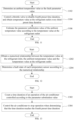
- the method for controlling the air conditioner includes:
- a parameter substitution value is estimated through operating parameters of the air conditioner.
- the parameter substitution value corresponds to the fault parameter value.
- the air conditioner provided in this embodiment is used for controlling the air conditioner, indoor unit(s) and a plurality of temperature sensors are provided in the air conditioner.
- the plurality of temperature sensors are located at different positions of the indoor unit.
- the plurality of temperature sensors may collect temperature parameter values at different positions respectively.
- a throttle valve and a draught fan are further provided in the indoor unit, the throttle valve and the draught fan of the indoor unit are controlled according to the plurality of corresponding temperature parameter values collected by the plurality of temperature sensors.
- the control of the operation of the indoor unit is realized.
- the indoor unit of the air conditioner collects the temperature parameter values continuously through the plurality of temperature sensors, and collects the operating parameters of the air conditioner continuously, and controls the operation of the air conditioner according to the collected temperature parameter values and the operating parameters.
- the throttle valve and the draught fan in the indoor unit are controlled through the temperature parameter values collected by the temperature sensors.
- Whether there exists a malfunctioned temperature sensor in the indoor unit is detected during the operation of the air conditioner.
- the malfunctioned sensors in the plurality of temperature sensors are detected and located.
- the fault parameter values in the temperature parameter values collected by the plurality of temperature sensors may be determined, and the true value of the fault parameter value is estimated through other operating parameters of the air conditioner, and thus the parameter substitution value is obtained.
- the fault parameter value in the plurality of temperature parameter values is substituted with the parameter substitution value, and updating of the plurality of collected temperature parameter values is realized.
- the operation of the air conditioner is continued to be controlled through the parameter substitution value.
- the indoor unit of the air conditioner can still keep operation under the condition that there exists a malfunctioned temperature sensor in the indoor unit of the air conditioner. It is guaranteed that the air conditioner can still be operated in the queueing process for maintenance, a downtime of the air conditioner in the queueing process for maintenance is shortened, and a usage experience of a user is improved.
- the air conditioner when detecting that there exists malfunctioned temperature sensor(s) in the air conditioner, the air conditioner outputs corresponding prompt information for prompting fault(s) of the temperature sensor(s).
- the air conditioner after the air conditioner detects that there exists a malfunctioned temperature sensor in the plurality of temperature sensors, after the air conditioner receives an operation instruction from the user, the air conditioner continues to perform the step of estimating the parameter substitution value, and controlling the operation of the air conditioner through the parameter substitution value.
- the air conditioner may determine whether continuous operation needs to performed according to the actual requirement of the user. If the air conditioner fails to receive the operation instruction from the user, the air conditioner is controlled to stop operation after outputting prompt information of "fault and halt". A controllability of the air conditioner is improved, and the air conditioner may select to continue to be operated or stop operation according to the requirement of the user when temperature sensor(s) is/are in the fault state.
- a heat exchanger 202 is arranged in the indoor unit 200, the temperature sensors includes a first temperature sensor 204, a second temperature sensor 206, and a third temperature sensor 208.
- the first temperature sensor 204 and the second temperature sensor 206 are arranged at two ends of the heat exchanger 202, the third temperature sensor 208 is arranged at an air inlet of the indoor unit 200.
- the indoor unit 200 of the air conditioner includes the heat exchanger 202, when the air conditioner is operated in a refrigeration mode, refrigerant flows to a second end through a first end of the heat exchanger 202.
- the refrigerant flows to the first end through the second end of the heat exchanger 202.
- a plurality of temperature sensors are further arranged in the indoor unit 200.
- the plurality of temperature sensors include the first temperature sensor 204 arranged at the first end of the heat exchanger 202.
- the first temperature sensor 204 may collect a temperature value at the refrigerant inlet of the indoor unit 200 under a refrigeration mode.
- the first temperature sensor 204 may collect a temperature value at a refrigerant outlet of the indoor unit 200 under a heating mode.
- the plurality of temperature sensors further include the second temperature sensor 206 arranged at the second end of the heat exchanger 202, the second temperature sensor 206 may detect a temperature value at a refrigerant outlet of the indoor unit 200 in the refrigeration mode.
- the second temperature sensor 206 may collect a temperature value at the refrigerant inlet of the indoor unit 200 under the heating mode.
- the plurality of temperature sensors further include a third temperature sensor 208 arranged at the air inlet of the indoor unit 200, and the third temperature sensor 208 may collect the temperature of the air entering the indoor unit 200. That is, the third temperature sensor 208 may collect the ambient temperature value of the indoor unit 200.
- the step of determining the fault parameter value in the at least two temperature parameter values specifically includes: In a step of S302, a fault state of the first temperature sensor, a fault state of the second temperature sensor, and a fault state of the third temperature sensor are detected respectively.
- a corresponding fault parameter value is determined according to the fault state of the first temperature sensor, the fault state of the second temperature sensor, and the fault state of the third temperature sensor.
- the fault parameter value includes a temperature value at the refrigerant inlet, a temperature value at the refrigerant outlet, and an ambient temperature value.
- the indoor unit of the air conditioner is provided with a throttle valve and a draught fan, during the operation of the indoor unit, the operation of the indoor unit is controlled by controlling parameters such as an opening degree of the throttle valve and a rotation speed of the draught fan.
- the detail of the control method includes: adjusting the opening degree of the throttle valve according to the collected temperature value at the refrigerant outlet, the ambient temperature value, and the temperature value at the refrigerant inlet, and adjusting the rotation speed of the draught fan.
- Whether there exists a fault parameter value in the plurality of temperature parameter values is determined by determining whether each of the plurality of temperature sensors in the indoor unit of the air conditioner malfunctions. When a malfunctioned temperature sensor in the plurality of temperature sensors is detected, it is determined that a fault parameter value is included in the collected multiple temperature parameter values.
- the fault parameter value in the temperature parameter values collected by the three temperature sensors may be determined by determining whether the three temperature sensors malfunction respectively, under the determination of the operation mode of the air conditioner.
- the fault parameter value in the collected temperature parameter values is determined rapidly when there exists a malfunctioned temperature sensor in the indoor unit, and the air conditioner is prevented from being continuously controlled according to the fault parameter value, the duration of operation of the air conditioner in the fault state is reduced.
- the method before estimating the parameter substitution value through the operating parameters of the air conditioner, the method includes: In a step of S402, the air conditioner is controlled to be operated in a preset operation mode.
- step of S404 operating parameters of the air conditioner are collected in the preset operation mode.
- the preset operation mode includes a refrigeration mode and a heating mode.
- control parameters and the operating parameters of the air conditioner operated in the refrigeration mode and the control parameters and the operating parameters of the air conditioner operated in the heating mode are different, flow directions of the refrigerant flowing through the heat exchanger of the indoor unit are also different when the air conditioner is operated in different modes.
- the temperature parameter values collected by the first temperature sensor and the second temperature sensor are also different.
- the current operation mode of the air conditioner needs to be determined before estimating the parameter substitution value, the fault parameter value is determined according to the operation mode and whether each temperature sensor in the plurality of temperature sensors malfunctions.
- the corresponding operating parameters are collected in the process of operating the air conditioner in the preset operation mode, then, the parameter substitution value is estimated through the collected operating parameters.
- the calculated parameter substitution value is consistent with the operation mode of the air conditioner, an accuracy of operation of the air conditioner according to the parameter substitution value is improved, and a malfunction of the air conditioner caused due to the control of the air conditioner according to the parameter substitution value that does not conform to the operation mode is avoided.
- the operation mode of the air conditioner further includes an air supplying mode, when the air conditioner is in the air supplying mode, a compressor of the air conditioner does not need to be operated, and a cut-off valve in the indoor unit does not need to be started, either.
- the malfunction of the temperature sensor does not affect air supplying operation of the air conditioner, and thus the corresponding parameter substitution value does not need to be estimated.
- a fault of the first temperature sensor of the air conditioner is detected.
- the temperature value at the refrigerant inlet in the collected temperature parameter values is determined as the fault parameter value.
- the temperature value at the refrigerant outlet in the collected temperature parameter values is determined as the fault parameter value.
- a fault of the second temperature sensor of the air conditioner is detected.
- the temperature value at the refrigerant outlet in the collected temperature parameter values is determined as the fault parameter value.
- the temperature value at the refrigerant inlet in the collected temperature parameter values is determined as the fault parameter value.
- a fault of the third temperature sensor of the air conditioner is detected. Since the temperature parameter value collected by the third temperature sensor is the ambient temperature value, the ambient temperature value in the collected temperature parameter values is determined as the fault parameter value.
- the fault in the first temperature sensor is determined, and the air conditioner includes a plurality of indoor units.
- the step of estimating the parameter substitution value through the operating parameters of the air conditioner specifically includes:
- the temperature value at the refrigerant outlet is determined as the fault parameter value according to the operation of the air conditioner in the heating mode.
- the number of the indoor units in the operating state is determined.
- a preset amount of heat output a pressure value at the refrigerant outlet, a target subcooling degree, and a high-pressure saturation temperature.
- the parameter substitution value of the temperature value at the refrigerant outlet is estimated according to the preset amount of heat output, the pressure value at the refrigerant outlet, the target subcooling degree and the high-pressure saturation temperature.
- the air conditioner is a multi-split air conditioner, that is, the air conditioner includes a plurality of indoor units.
- the air conditioner is operated according to the heating mode, and the high-temperature and high-pressure refrigerant generated by the compressor flows to the first end of the heat exchanger of the indoor unit through the second end of the heat exchanger of the indoor unit. Since the first temperature sensor is arranged at the first end of the heat exchanger, the temperature parameter value collected by the first temperature sensor is the temperature value at the refrigerant outlet. When the first temperature sensor is in a fault state, the temperature value at the refrigerant outlet may be determined as the fault parameter value.
- the number of the started indoor units in the air conditioner needs to be determined, and the operating parameters including the high-pressure saturation temperature of the air conditioner, the preset amount of heat output, the pressure value at the refrigerant outlet, the target subcooling degree of the indoor unit are obtained.
- the parameter substitution value is estimated through the obtained operating parameters and the number of the indoor unit in operation, and the temperature value at the refrigerant outlet in the collected temperature parameter values is substituted with the parameter substitution value.
- the high-voltage saturation temperature is the hardware parameter of the air conditioner system.
- the high-voltage protection temperature of the system may be directly invoked.
- the target subcooling degree is the parameter value obtained through calculation according to an operation instruction after the operation instruction is received by the air conditioner.
- the pressure value at the refrigerant outlet may be directly collected by arranging the pressure sensors.
- the pressure value at the refrigerant outlet may be calculated through other parameter values such as the temperature at the refrigerant outlet.
- the preset heat output may be calculated according to the high-pressure saturation temperature and the ambient environment.
- the step of estimating the parameter substitution value of the temperature value at the refrigerant outlet specifically includes:
- step of S602 it is determined that the air conditioner is operated in a heating mode.
- a step of S604 whether the number of indoor units is less than a preset number is determined; if the number of the indoor units is less than the preset number, a step of S606 is performed; if the number of the indoor units is equal to or greater than the preset number, a step of S608 is performed.
- the parameter substitution value of the temperature value at the refrigerant outlet is estimated according to the target subcooling degree and the high-pressure saturation temperature.
- the parameter substitution value of the temperature value at the refrigerant outlet is estimated according to the preset amount of heat output and the pressure value at the refrigerant outlet.
- the parameter substitution value of the temperature value at the refrigerant outlet is obtained by calculating the difference value between the high-voltage saturation temperature and the target subcooling degree, and the estimated temperature value at the refrigerant outlet is used as the parameter substitution value of the temperature value at the refrigerant outlet.
- T 1 is the parameter substitution value corresponding to the temperature value at the refrigerant outlet
- T C is the high-voltage saturation temperature
- SCS is the target subcooling degree
- the temperature sensor in each indoor unit malfunctions is detected. If a fault-free indoor unit is detected, a pressure value at the refrigerant outlet of an indoor unit without sensor fault is calculated, and a pressure value at the refrigerant outlet of an indoor unit having a sensor fault is calculated, the preset amount of heat output is obtained according to the two pressure values at the refrigerant outlet, enthalpy value of the refrigerant outlet of the heat exchanger is calculated according to the preset amount of heat output, and the temperature value at the refrigerant outlet is estimated according to the enthalpy value of the refrigerant outlet, and the parameter substitution value corresponding to the temperature value at the refrigerant outlet is calculated accordingly.
- P 1 is the pressure value at the refrigerant outlet of the indoor unit without sensor fault
- P C is the maximum pressure value of an outdoor unit
- dP 1 is a pressure drop across an electronic expansion valve of the indoor unit without sensor fault.
- the pressure drop across the electronic expansion valve of the indoor unit without sensor fault may be calculated by calculating the pressure values at the two ends of the electronic expansion valve collected by the sensors.
- the pressure drop may also be obtained by calculation according to a refrigerant flow value, the enthalpy value of the refrigerant outlet, and the preset amount of heat output of the indoor unit.
- H 1 is a liquid column pressure value caused due to height difference between a malfunctioned indoor unit and a reference point
- Hz is the liquid column pressure value caused due to height difference between the indoor unit having a sensor fault and the reference point
- den is a density of the refrigerant of the malfunctioned indoor unit
- P 2 is the pressure value at the refrigerant outlet of the malfunctioned indoor unit
- P 1 is the pressure value at the refrigerant outlet of the indoor unit without sensor fault.
- the liquid column pressure value caused due to the height difference between the indoor unit and the reference point is calculated during a trial operation stage of the air conditioner.
- the density of the refrigerant may be obtained by calculating a physical property function of the liquid refrigerant, and a segmented fitting curve may be adopted in the process of calculation of the density of the refrigerant.
- mf is the refrigerant flow value
- dP 2 is the pressure drop across the electronic expansion valve of the indoor unit having a sensor fault
- cv is an opening value of the electronic expansion valve
- den is the density of the refrigerant of the malfunctioned indoor unit.
- dp 2 is the pressure drop across the electronic expansion valve of the indoor unit having a sensor fault
- P C is the maximum pressure value of the outdoor unit
- P 2 is the pressure value at the refrigerant outlet of the malfunctioned indoor unit.
- Q is the preset amount of heat output
- K A is a coefficient
- T C is the high-voltage saturation temperature
- T 3 is the ambient temperature value.
- H 1 is an enthalpy value of the refrigerant outlet
- H 2 is an enthalpy value at the refrigerant inlet
- Q is a preset amount of heat output
- mf is the refrigerant flow value.
- T 1 is the parameter substitution value corresponding to the temperature value at the refrigerant outlet
- hi is the enthalpy value of the refrigerant outlet
- T C is the high-voltage saturation temperature
- f 1 is a preset function.
- the parameter substitution value of the temperature value at the refrigerant outlet of the indoor unit having a sensor fault is accurately obtained by collecting corresponding parameters of the indoor unit without sensor fault and calculating according to the corresponding parameters, under the condition that a plurality of indoor units are powered on.
- the accuracy of operation of the air conditioner controlled according to the parameter substitution value is further improved, and occurrence of other faults during the operation process of the air conditioner is avoided.
- a value range of the preset number is greater than or equal to 2.
- the parameter substitution value of the temperature value at the refrigerant outlet of the indoor unit having sensor fault is calculated by collecting corresponding parameters of the indoor unit having the fault-free sensor(s).
- the parameter substitution value of the temperature value at the refrigerant outlet of the indoor unit having a plurality of malfunctioned sensors may be calculated by collecting corresponding parameters of one indoor unit without sensor fault, the control of the operation of the indoor unit having the plurality of malfunctioned sensors in the air conditioner is realized, and the inconvenience caused due to termination of operation of the air conditioner is avoided.
- the step of estimating the parameter substitution value through the operating parameters of the air conditioner specifically includes:
- the temperature value at the refrigerant inlet is determined as the fault parameter value according to the operation of the air conditioner in the refrigeration mode.
- the draught fan is controlled to stop operation for a second preset time duration every first preset time duration, and the temperature value at the refrigerant outlet is collected.
- the parameter substitution value of the temperature value at the refrigerant inlet is estimated according to the temperature value at the refrigerant outlet.
- the air conditioner is a multi-split air conditioner, that is, the air conditioner includes a plurality of indoor units.
- the air conditioner is operated in the refrigeration mode, and the refrigerant flows from the first end of the heat exchanger to the second end of the heat exchanger. Since the first temperature sensor is arranged at the first end of the heat exchanger, the temperature parameter value collected by the first temperature sensor is the temperature value at the refrigerant inlet. When the first temperature sensor is in the fault state, the temperature value at the refrigerant inlet may be determined as the fault parameter value.
- the temperature value at the refrigerant inlet is the fault parameter value.
- a substitution value of the temperature value at the refrigerant inlet may be estimated according to the temperature value at the refrigerant outlet.
- the low-temperature refrigerant flows to the second end of the heat exchanger of the indoor unit through the first end of the heat exchanger of the indoor unit. During the process in which the refrigerant flows through the heat exchanger, the low-temperature refrigerant continuously exchanges heat with ambient air.
- the temperature value at the refrigerant outlet should be higher than the temperature value at the refrigerant inlet, the difference value between the temperature value at the refrigerant outlet and the first preset difference value is calculated, and the estimated temperature value at the refrigerant inlet may be obtained, the estimated temperature value at the refrigerant inlet is used as the parameter substitution value of the temperature value at the refrigerant inlet, and the temperature value at the refrigerant inlet in the collected temperature parameter values is substituted with the parameter substitution value.
- T 1 represents the parameter substitution value corresponding to the temperature value at the refrigerant inlet
- T 2 represents the temperature value at the refrigerant outlet
- Z 1 represents the first preset difference value
- the estimated parameter substitution value of the refrigerant inlet is updated every first preset time duration.
- the updating method includes: collecting the temperature value at the refrigerant outlet every first preset time duration, and then re-estimating the parameter substitution value of the temperature value at the refrigerant inlet according to the temperature value at the refrigerant outlet.
- the parameter substitution value of the temperature value at the refrigerant inlet is continuously updated, the stability of the control of the air conditioner having a sensor fault is further improved.
- the temperature value at the refrigerant outlet is collected every first preset time duration, and the parameter substitution value is estimated according to the temperature value at the refrigerant outlet.
- the draught fan is controlled to stop operation for a second preset time duration. It can be understood that the operation of the draught fan may accelerate the heat exchange between the heat exchanger and ambient air.
- the draught fan is controlled to stop operation for the second preset time duration, the value of energy loss of the refrigerant in the heat exchange process may be decreased, and an accuracy of an estimated parameter substitution value of the temperature value at the refrigerant inlet is further improved.
- a value range of the second preset time duration is between 10 seconds and 40 seconds.
- the value of the second preset time duration is set to be greater than or equal to 10 seconds, such that there is enough time for the temperature value at the refrigerant outlet to approach the temperature value at the refrigerant inlet.
- the value of the second preset time duration is set to be less than or equal to 40 seconds, such that a malfunction of air conditioner caused due to long time of poor heat exchange of refrigerant in the heat exchanger may be avoided.
- the second temperature sensor is in the fault state
- the step of estimating the parameter substitution value through the operating parameters of the air conditioner specifically includes:
- the temperature value at the refrigerant inlet is determined as the fault parameter value according to the operation of the air conditioner in the heating mode.
- the parameter substitution value of the temperature value at the refrigerant inlet is estimated according to the high-pressure saturation temperature.
- the air conditioner is a multi-split air conditioner, that is, the air conditioner includes a plurality of indoor units.
- the air conditioner is operated in the heating mode, the high-temperature and high-pressure refrigerant generated by the compressor flows to the first end of the heat exchanger of the indoor unit through the second end of the heat exchanger of the indoor unit. Since the first temperature sensor is arranged at the first end of the heat exchanger, the temperature parameter value collected by the first temperature sensor is the temperature value at the refrigerant outlet. When the first temperature sensor is in the fault state, the temperature value at the refrigerant outlet may be determined as the fault parameter value.
- the substitution value of the temperature value at the refrigerant inlet may be estimated according to the high-pressure saturation temperature.
- the high-temperature refrigerant compressed by the compressor directly flows to the second end of the heat exchanger, thus, the parameter substitution value of the relatively accurate temperature value at the refrigerant inlet may be obtained by estimating according to hardware parameters of the air conditioning system.
- the high-pressure saturation temperature is the temperature value corresponding to the refrigerant under a certain pressure, it may be considered that the high-pressure saturation temperature is the temperature value of the high-pressure and high-temperature refrigerant output by the compressor, the high-temperature and high-pressure refrigerant flows to the second end of the heat exchanger of the indoor unit through a refrigerant pipeline, and certain heat loss is caused.
- the second preset difference value is arranged according to heat loss.
- the temperature value at the refrigerant inlet of the heat exchanger in the heating mode may be estimated by calculating the difference value between the high-pressure saturation temperature and the second preset difference value, and the estimated temperature value at the refrigerant inlet is taken as the parameter substitution value of the temperature value at the refrigerant inlet, and the temperature value at the refrigerant inlet in the collected temperature parameter values is substituted with the parameter substitution value.
- T 2 is the parameter substitution value corresponding to the temperature value at the refrigerant inlet
- T C is the high-voltage saturation temperature
- Z 2 is the second preset difference value
- the compressor will continue to be operated in the preset operation state, that is, variation ranges of the pressure value and the temperature value of the refrigerant output by the compressor are relatively small.
- the operation of the air conditioner is continuously controlled according to the parameter substitution value calculated by the high-voltage saturation temperature and the second preset difference value, the parameter substitution value does not need to be frequently updated.
- the second temperature sensor is in the fault state
- the air conditioner includes a plurality of indoor units.
- the step of estimating the parameter substitution value according to the operating parameters of the air conditioner specifically includes:
- the temperature value at the refrigerant outlet is determined as the fault parameter value according to the operation of the air conditioner in the refrigeration mode.
- a step of S904 the number of indoor units in the operation state is determined.
- the target superheat degree, the temperature value at the refrigerant inlet, the temperature of the exhaust air of the compressor, the preset amount of heat output, and the target superheat degree of the exhaust air of the compressor are collected.
- the parameter substitution value of the temperature value at the refrigerant outlet is estimated according to the number of indoor units, the target superheat degree, the temperature value at the refrigerant inlet, the temperature of the exhaust air of the compressor, the preset amount of heat output and the target superheat degree of the exhaust air of the compressor.
- the air conditioner is a multi-split air conditioner, that is, the air conditioner includes a plurality of indoor units.
- the air conditioner is operated in the refrigeration mode, and the refrigerant flows from the first end of the heat exchanger to the second end of the heat exchanger. Since the second temperature sensor is arranged at the second end of the heat exchanger, the temperature parameter value collected by the second temperature sensor is the temperature value at the refrigerant outlet. When the second temperature sensor is in the fault state, the temperature value at the refrigerant outlet may be determined as the fault parameter value.
- the number of the started indoor units in the air conditioner needs to be determined, the temperature value at the refrigerant inlet of the air conditioner, the preset amount of heat output and the target superheat degree, and the temperature of the exhaust air of the compressor and the target superheat degree of the exhaust air of the compressor are obtained.
- the parameter substitution value is estimated through the obtained operating parameters and the number of the started indoor units, and the temperature value at the refrigerant outlet in the collected temperature parameter values is substituted with the parameter substitution value.
- the step of estimating the parameter substitution value of the temperature value at the refrigerant outlet specifically includes:
- step of S 1002 operation of the air conditioner in the refrigeration mode is determined.
- a step of S 1004 whether the number of indoor units is less than a preset number is determined; if the number of indoor units is less than the preset number, a step of S 1006 is performed, if the number of indoor units is equal to or greater than the preset number, a step of S1008 is performed.
- the parameter substitution value of the temperature value at the refrigerant outlet is estimated according to the target superheat degree and the temperature value at the refrigerant inlet.
- the parameter substitution value of the temperature value at the refrigerant outlet is estimated according to temperature of the exhaust air, the superheat degree of the exhaust air, the target superheat degree, and the temperature at the refrigerant inlet.
- an estimated temperature value at the refrigerant outlet is obtained by calculating according to the temperature value at the refrigerant inlet and the target superheat degree, and the estimated temperature value at the refrigerant outlet is used as the parameter substitution value of the temperature value at the refrigerant outlet.
- T 2 is the parameter substitution value corresponding to the temperature value at the refrigerant outlet
- T 1 is the temperature value at the refrigerant inlet
- SHS is the target superheat degree
- the parameter substitution value of the temperature value at the refrigerant outlet is calculated according to the superheat degree of the exhaust air, the temperature value at the refrigerant inlet, the temperature of the exhaust air and the target superheat degree, so that an estimated temperature value at the refrigerant outlet is obtained, and the estimated temperature value at the refrigerant rear outlet is used as the parameter substitution value of the temperature value of the refrigerant rear outlet.
- T 2 is the parameter substitution value corresponding to the temperature value at the refrigerant outlet
- T 1 is a temperature value at a refrigerant inlet
- SHS is the target superheat degree
- DSHS is the target superheat degrees of the exhaust air
- DSH is the temperature of the exhaust air.
- the parameter substitution value of the temperature value at the refrigerant outlet of the indoor unit having a malfunctioned sensor is obtained by collecting the corresponding parameters of the indoor unit and accurately calculating according to these parameters through the aforesaid formula. Furthermore, the accuracy of controlling the air conditioner to be operated through the parameter substitution value is further improved, and an occurrence of other faults in the operation process of the air conditioner is avoided.
- the step of estimating the parameter substitution value according to the operating parameters of the air conditioner specifically includes: In a step of S1102, an ambient temperature value is determined as the fault parameter value.
- the throttle valve is controlled to inactivate the fourth preset time duration every third preset time duration and the temperature value at the refrigerant outlet is obtained.
- the parameter substitution value of the ambient temperature value is estimated according to the temperature value at the refrigerant outlet.
- the ambient temperature value collected by the third temperature sensor is determined as the fault parameter value.
- the substitution value of the ambient temperature value may be estimated according to the temperature value at the refrigerant outlet.
- the estimated ambient temperature value may be obtained by calculating the temperature value at the refrigerant outlet and the third preset difference value, the estimated ambient temperature value is used as the parameter substitution value of the ambient temperature value, and the ambient temperature value in the collected temperature parameter values is replaced by the parameter substitution value.
- T 3 is the parameter substitution value of the ambient temperature value
- T 2 is the temperature value at the refrigerant outlet
- Z 3 is the third preset difference value
- a difference value between the temperature value at the refrigerant outlet and the ambient temperature value when the air conditioner is operated in the refrigeration mode and a difference value between the temperature value at the refrigerant outlet and the ambient temperature value when the air conditioner is operated in the refrigeration mode are different.
- different third preset difference values are selected according to different operation modes of the air conditioner before the step of calculating the parameter substitution value of the ambient temperature value.
- the third preset time duration is set, and the substitution value of the estimated ambient temperature value is updated.
- the updating method includes: collecting the temperature value at the refrigerant outlet every third preset time duration, and then re-estimating the parameter substitution value of the ambient temperature value according to the temperature value at the refrigerant outlet.
- the parameter substitution value of the ambient temperature value is continuously updated, the stability of the control of the air conditioner having a sensor fault is further improved.
- the temperature value at the refrigerant outlet is collected every third preset time duration, and the parameter substitution value is estimated according to the temperature value at the refrigerant outlet.
- the throttle valve is controlled to stope operation for the fourth preset time duration. It can be understood that when the throttle valve is in an open state, the low-temperature or high-temperature refrigerant continues to flow into the heat exchanger, and a great difference between the temperature value at the refrigerant outlet and the ambient temperature value is caused.
- the throttle valve is controlled to stop operation for the fourth preset time duration, the difference between the temperature value at the refrigerant outlet and the ambient temperature value may be reduced, and the accuracy of the estimated parameter substitution value of the temperature value at the refrigerant inlet is further improved.
- a value range of the fourth preset time duration is between 60 seconds and 120 seconds.
- the value of the fourth preset time duration is set to be greater than or equal to 60 seconds, thus, there is enough time for the temperature value at the refrigerant outlet for approaching the ambient temperature value.
- the value of the fourth preset time duration is set to be less than or equal to 120 seconds, such that the malfunction of the air conditioner caused because that the refrigerant cannot enter the heat exchanger of the indoor unit for long time may be avoided.
- the step of detecting the fault state of the first temperature sensor, the fault state of the second temperature sensor, and the fault state of the third temperature sensor respectively specifically includes:
- a numerical relationship between the temperature value at the refrigerant inlet, the ambient temperature value, and the temperature value at the refrigerant outlet is determined.
- the fault state of each of the temperature sensors is determined according to the numerical relationship.
- whether there exists a malfunctioned temperature sensor in the three temperature sensors is detected according to the data relationship between the temperature parameter value collected by the first temperature sensor, the temperature parameter value collected by the second temperature sensor and the temperature parameter value collected by the third temperature sensor. Moreover, the malfunctioned temperature sensor in the three temperature sensors may be located.
- the temperature value at the refrigerant inlet, the ambient temperature value, and the temperature value at the refrigerant outlet are collected, and it is determined that two of the temperature value at the refrigerant inlet, the ambient temperature value and the temperature value at the refrigerant outlet are not fault parameter values.
- the compressor of the air conditioner stops operation, which lasts for a fifth preset time duration.
- the other temperature parameter value is determined as the fault parameter value when the following determination conditions are satisfied, the determination conditions are expressed as: Abs T 3 ⁇ T 1 ⁇ dT 2 ⁇ Abs T 3 ⁇ T 2 ⁇ dT 2 ⁇ Abs T 2 ⁇ T 1 ⁇ dT 2 ⁇ 0 , and Abs T 2 ⁇ T 1 ⁇ dT 2 , and Abs T 3 ⁇ T 1 ⁇ dT 2 ;
- the air conditioner is operated according to the refrigeration mode.
- the other temperature parameter value is determined as the fault parameter value when the following determination conditions are satisfied, the determination conditions are expressed as: T 1 ⁇ T 3 ⁇ dT 2 ⁇ T 2 ⁇ T 3 ⁇ dT 1 ⁇ T 1 ⁇ T 2 ⁇ dT 3 ⁇ 0 reaches a preset time length , and T 1 ⁇ T 2 ⁇ dT 2 , and T 1 ⁇ T 3 ⁇ dT 1 ;
- the air conditioner is operated according to the heating mode.
- the other temperature parameter value is determined as the fault parameter value when the following determination conditions are satisfied, the determination conditions are expressed as: T 3 ⁇ T 1 ⁇ dT 1 ⁇ T 3 ⁇ T 2 ⁇ dT 1 ⁇ T 1 ⁇ T 2 ⁇ dT 4 ⁇ 0 reaches a preset time length , and T 1 ⁇ T 2 ⁇ dT 4 , and T 3 ⁇ T 1 ⁇ dT 1 .
- T 1 is the temperature parameter value collected by the first temperature sensor
- T 2 is the temperature parameter value collected by the second temperature sensor
- T 3 is the temperature parameter value collected by the third temperature sensor
- dT 1 is a first preset value
- dT 2 is a second preset value
- dT 3 is a third preset value
- dT 4 is a fourth preset value.
- the method for controlling the air conditioner further includes:
- a time duration of the operation of the air conditioner controlled according to the parameter substitution value is counted.
- the air conditioner is controlled to stop operation one the basis that the time duration reaches the fourth preset time duration.
- the air conditioner is controlled to stop operation. Since the parameter substitution value of the temperature parameter value is the estimated temperature parameter value, there is a certain difference between the parameter substitution value of the temperature parameter value and a true value of the temperature parameter value. After the time duration of the operation of the air conditioner controlled according to the estimated temperature parameter value reaches the fourth time duration, the air conditioner is controlled to stop operation. Thus, the air conditioner may be prevented from being operated under a fault state of one temperature sensor for a long time. The stability of operation of the air conditioner is improved.
- an apparatus 1400 for controlling an air conditioner is provided the first embodiment of the present application.
- the apparatus 1400 includes:
- the apparatus for controlling the air conditioner provided in the present application is used for controlling the air conditioner, one indoor unit and a plurality of temperature sensors are arranged in the air conditioner, the plurality of temperature sensors are provided at different positions of the indoor unit, and the plurality of temperature sensors may respectively collect temperature parameter values at the different positions.
- a throttle valve and a draught fan are further provided in the indoor unit, and the throttle valve and the draught fan of the indoor unit are controlled according to the plurality of corresponding temperature parameter values collected by the plurality of temperature sensors, and a control of operation of the indoor unit is realized.
- the indoor unit of the air conditioner collects the temperature parameter values continuously through the plurality of temperature sensors, and collects the operating parameters of the air conditioner continuously, and controls the operation of the air conditioner according to the collected temperature parameter values and the collected operating parameters.
- the throttle valve and the draught fan in the indoor unit are controlled through the temperature parameter values collected by the temperature sensors.
- Whether there exists malfunctioned temperature sensor(s) arranged in the indoor unit is detected during the operation of the air conditioner.
- a fault sensor in the plurality of temperature sensors is detected and located.
- the fault parameter value in the temperature parameter values collected by the plurality of temperature sensors may be determined, and the true value of the fault parameter value is estimated through other operating parameters of the air conditioner and the parameter substitution value is obtained.
- the plurality of collected temperature parameter values is updated by replacing the fault parameter value in the plurality of temperature parameter values with the parameter substitution value.
- the operation of the air conditioner is continued to be controlled through the parameter substitution value, such that the indoor unit of the air conditioner can still keep operation under the condition that the temperature sensor in the indoor unit of the air conditioner are in the fault state. It is ensured that the air conditioner can still be operated in a queueing process for maintenance, a downtime of the air conditioner in the queueing process for maintenance is shortened. Thus, a use experience of the user is improved.
- the air conditioner when a malfunctioned temperature sensor in the air conditioner is detected, the air conditioner outputs corresponding prompt information for prompting a fault of the temperature sensor.
- the air conditioner after the air conditioner detects that there exists a malfunctioned temperature sensor in the plurality of temperature sensors, after the air conditioner receives an operation instruction from the user, the air conditioner continues to perform the step of estimating the parameter substitution value, and controlling the air conditioner to be operated according to the parameter substitution value.
- the air conditioner may determine whether continuous operation needs to performed according to the actual requirement of the user. If the air conditioner fails to receive the operation instruction from the user, the air conditioner is controlled to stop operation after outputting prompt information of "fault and halt". A controllability of the air conditioner is improved, and the air conditioner may select to continue to be operated or stop operation according to the requirement of the user when temperature sensor(s) is/are in the fault state.
- a heat exchanger 202 is arranged in the indoor unit 200.
- the temperature sensor includes a first temperature sensor 204, a second temperature sensor 206, and a third temperature sensor 208.
- the first temperature sensor 204 is arranged at a first end of the heat exchanger 202
- the second temperature sensor 206 is arranged at a second end of the heat exchanger 202
- the third temperature sensor 208 is arranged at an air inlet of the indoor unit 200.
- the indoor unit 200 of the air conditioner includes the heat exchanger 202.
- the refrigerant flows to the second end of the heat exchanger 202 through the first end of the heat exchanger 202.
- the air conditioner is operated in the heating mode, the refrigerant flows to the first end of the heat exchanger 202 through the second end of the heat exchanger 202.
- a plurality of temperature sensors are further arranged in the indoor unit 200.
- the plurality of temperature sensors include the first temperature sensor 204 arranged at the first end of the heat exchanger 202. In the refrigeration mode, the first temperature sensor 204 may detect the temperature value at the refrigerant inlet of the indoor unit 200.
- the first temperature sensor 204 may detect the temperature value at the refrigerant outlet of the indoor unit 200.
- the plurality of temperature sensors further includes the second temperature sensor 206 arranged at the second end of the heat exchanger 202.
- the second temperature sensor 206 may detect the temperature value at the refrigerant outlet of the indoor unit 200.
- the second temperature sensor 206 may detect the temperature value at the refrigerant inlet of the indoor unit 200.
- the plurality of temperature sensors further include the third temperature sensor 208 arranged at the air inlet of the indoor unit 200, and the third temperature sensor 208 may detect the temperature of the air entering the indoor unit 200, that is, the third temperature sensor 208 may detect the ambient temperature value of the indoor unit 200.
- an air conditioner 1500 is provided in the third embodiment of the present application, the air conditioner 1500 includes: an indoor unit 1502 and the apparatus 1400 for controlling the air conditioner.
- the apparatus 1400 for controlling the air conditioner is arranged in the indoor unit, and the apparatus 1400 for controlling the air conditioner is selected as the apparatus 1400 for controlling the air conditioner in the second embodiment.
- the apparatus 1400 for controlling the air conditioner is configured to control the air conditioner, one or a plurality of indoor unit(s) and a plurality of temperature sensors are provided in the air conditioner.
- the plurality of temperature sensors are arranged at different positions of the indoor unit, and the plurality of temperature sensors may collect temperature parameter values at different positions respectively.
- a throttle valve and a draught fan are further provided in the indoor unit, and the throttle valve and the draught fan of the indoor unit are controlled according to the plurality of corresponding temperature parameter values collected by the plurality of temperature sensors.
- the indoor unit of the air conditioner collects the temperature parameter values continuously through the plurality of temperature sensors, collects the operating parameters of the air conditioner continuously, and controls the operation of the air conditioner according to the collected temperature parameter values and the operating parameters.
- the throttle valve and the draught fan in the indoor unit are controlled through the temperature parameter values collected by the temperature sensor.
- Whether there exists malfunctioned temperature sensor(s) arranged in the indoor unit is detected during the operation of the air conditioner.
- a fault sensor in the plurality of temperature sensors is detected and located.
- the fault parameter value in the temperature parameter values collected by the plurality of temperature sensors may be determined, and the true value of the fault parameter value is estimated through other operating parameters of the air conditioner and the parameter substitution value is obtained.
- the plurality of collected temperature parameter values is updated by replacing the fault parameter value in the plurality of temperature parameter values with the parameter substitution value.
- the operation of the air conditioner is continued to be controlled through the parameter substitution value, such that the indoor unit of the air conditioner can still keep operation under the condition that the temperature sensor in the indoor unit of the air conditioner are in the fault state. It is ensured that the air conditioner can still be operated in a queueing process for maintenance, a downtime of the air conditioner in the queueing process for maintenance is shortened. Thus, a use experience of the user is improved.
- the air conditioner when one malfunctioned temperature sensor in the air conditioner is detected, the air conditioner outputs corresponding prompt information for prompting a fault of the temperature sensor.
- the air conditioner after the air conditioner detects that there exist one malfunctioned temperature sensor in the plurality of temperature sensors, after the air conditioner receives an operation instruction from the user, the air conditioner continues to perform the step of estimating the parameter substitution value and controlling the operation of the air conditioner according to the parameter substitution value.
- the air conditioner may determine whether continuous operation needs to performed according to the actual requirement of the user. If the air conditioner fails to receive the operation instruction from the user, the air conditioner is controlled to stop operation after outputting prompt information of "fault and halt". A controllability of the air conditioner is improved, and the air conditioner may select to continue to be operated or stop operation according to the requirement of the user when temperature sensor(s) is/are in the fault state.
- the air conditioner further includes an outdoor unit and a refrigerant pipeline, the outdoor unit is connected to the indoor unit through the refrigerant pipeline.
- an air conditioner 1600 is provided in the fourth embodiment of the present application, the air conditioner 1600 includes at least two indoor units 200, a memory 1602, and a processor 1604.
- a heat exchanger is arranged in the indoor unit 200, and the temperature sensor includes a first temperature sensor, a second temperature sensor and a third temperature sensor.
- the first temperature sensor is arranged at a first end of the heat exchanger
- the second temperature sensor is arranged at a second end of the heat exchanger
- the third temperature sensor is arranged at an air inlet of the indoor unit 200.
- the indoor unit 200 is provided with the heat exchanger 202, the temperature sensor includes the first temperature sensor 204, the second temperature sensor 206 and the third temperature sensor 208.
- the first temperature sensor 204 is arranged at the first end of the heat exchanger 202
- the second temperature sensor 206 is arranged at the second end of the heat exchanger 202
- the third temperature sensor 208 is arranged at the air inlet of the indoor unit 200.
- the indoor unit 200 of the air conditioner 1600 includes the heat exchanger 202.
- the refrigerant flows to the second end of the heat exchanger 202 through the first end of the heat exchanger 202.
- the air conditioner 1600 is operated in the heating mode, the refrigerant flows to the first end of the heat exchanger 202 through the second end of the heat exchanger 202.
- a plurality of temperature sensors are further disposed in the indoor unit 200.
- the plurality of temperature sensors include a first temperature sensor 204 arranged at a first end of the heat exchanger 202. In the refrigeration mode, the first temperature sensor 204 may detect the temperature value at the refrigerant inlet of the indoor unit 200.
- the first temperature sensor 204 may detect the temperature value at the refrigerant outlet of the indoor unit 200.
- the plurality of temperature sensors further includes a second temperature sensor 206 arranged at the second end of the heat exchanger 202. In the refrigeration mode, the second temperature sensor 206 may detect the temperature value at the refrigerant outlet of the indoor unit 200. In the heating mode, the second temperature sensor 206 may detect the temperature value at the refrigerant inlet of the indoor unit 200.
- the plurality of temperature sensors further include a third temperature sensor 208 arranged at the air inlet of the indoor unit 200, and the third temperature sensor 208 may detect the temperature of the air entering the indoor unit 200, that is, the third temperature sensor 208 may detect the ambient temperature value of the indoor unit 200.
- a program or an instruction is stored in the memory 1602, and the processor 1604 is configured to execute the program or the instruction stored in the memory 1602 to implement the steps of the method for controlling the air conditioner 1600 in the first embodiment described above.
- the method for controlling the air conditioner 1600 is used for controlling the air conditioner 1600.
- Indoor unit(s) 200 and a plurality of temperature sensors are arranged in the air conditioner 1600, the plurality of temperature sensors are arranged at different positions of the indoor unit 200, and the plurality of temperature sensors may collect temperature parameter values at different positions respectively.
- the indoor unit 200 is further provided with a throttle valve and a draught fan. The throttle valve and the draught fan of the indoor unit 200 are controlled according to the plurality of corresponding temperature parameter values collected by the plurality of temperature sensors. Thus, the control of the operation of the indoor unit 200 is realized.
- the indoor unit 200 of the air conditioner 1600 collects the temperature parameter values continuously through the plurality of temperature sensors, collects the operating parameters of the air conditioner 1600 continuously, and controls the operation of the air conditioner 1600 according to the collected temperature parameter values and the operating parameters.
- the throttle valve and the draught fan in the indoor unit 200 are controlled according to the temperature parameter values collected by the temperature sensors.
- Whether there exists malfunctioned temperature sensor(s) arranged in the indoor unit 200 is detected during the operation of the air conditioner 1600.
- a fault sensor in the plurality of temperature sensors is detected and located.
- the fault parameter value in the temperature parameter values collected by the plurality of temperature sensors may be determined, and the true value of the fault parameter value is estimated through other operating parameters of the air conditioner 1600 and the parameter substitution value is obtained.
- the plurality of collected temperature parameter values is updated by replacing the fault parameter value in the plurality of temperature parameter values with the parameter substitution value.
- the operation of the air conditioner 1600 is continued to be controlled through the parameter substitution value, such that the indoor unit 200 of the air conditioner 1600 can still keep operation under the condition that the temperature sensor in the indoor unit 200 of the air conditioner 1600 are in the fault state. It is ensured that the air conditioner 1600 can still be operated in a queueing process for maintenance, a downtime of the air conditioner 1600 in the queueing process for maintenance is shortened. Thus, a use experience of the user is improved.
- the air conditioner 1600 when one malfunctioned temperature sensor in the air conditioner 1600 is detected, the air conditioner 1600 outputs corresponding prompt information for prompting a fault of the temperature sensor.
- the air conditioner 1600 after the air conditioner 1600 detects that there exists one malfunctioned temperature sensor in the plurality of temperature sensors, the air conditioner 1600 continues to perform the step of the estimating the parameter substitution value, and controlling the operation of the air conditioner 1600 according to the parameter substitution value, after receiving an operation instruction from the user.
- the air conditioner 1600 may determine whether continuous operation needs to performed according to the actual requirement of the user. If the air conditioner 1600 fails to receive the operation instruction from the user, the air conditioner 1600 is controlled to stop operation after outputting prompt information of "fault and halt". A controllability of the air conditioner 1600 is improved, and the air conditioner 1600 may select to continue to be operated or stop operation according to the requirement of the user when temperature sensor(s) is/are in the fault state.
- a readable storage medium is provided in the fifth embodiment of the present application.
- the storage medium stores a program, when the program is executed by a processor, the method for controlling the air conditioner in any one of the aforesaid embodiments is implemented.
- the storage medium has all beneficial technical effects of the method for controlling the air conditioner in any one of the aforesaid embodiments.
- the readable storage medium may be such as a read-only memory (Read-Only Memory, ROM), a random access memory (Random Access Memory, RAM), a magnetic disk, or an optical disc, etc.
- ROM read-only memory
- RAM random access memory
- magnetic disk a magnetic disk
- optical disc etc.
- connection may be interpreted as fixed connection, and may also be a detachable connection, or be an integral connection.
- Connect may be further interpreted as a direct connection or an indirect connection through intermediary.
- specific meanings of the terms in the present application may be interpreted according to specific conditions of the terms.
Landscapes
- Engineering & Computer Science (AREA)
- Mechanical Engineering (AREA)
- General Engineering & Computer Science (AREA)
- Combustion & Propulsion (AREA)
- Chemical & Material Sciences (AREA)
- Signal Processing (AREA)
- Physics & Mathematics (AREA)
- Mathematical Physics (AREA)
- Fuzzy Systems (AREA)
- Thermal Sciences (AREA)
- Health & Medical Sciences (AREA)
- Biomedical Technology (AREA)
- Fluid Mechanics (AREA)
- Air Conditioning Control Device (AREA)
Abstract
Description
- This application claims priority to
Chinese patent application No. 202110780857.X, filed with CNIPA on July 9, 2021 - The present application relates to the field of air conditioner control technologies, and more particularly, to a method for controlling an air conditioner, an apparatus for controlling an air conditioner, an air conditioner, and a readable storage medium.
- An air conditioner is provided with a plurality of temperature sensors, and the plurality of temperature sensors may detect a plurality of temperature parameter values in the air conditioner. In the related art, the air conditioner is controlled to stop operation in the event that one temperature sensor of an indoor unit of the air conditioner malfunctions, and inconvenience may be brought to a user.
- The present application aims to solve one of the technical problems existing in the related art or related technologies.
- For this purpose, a method for controlling an air conditioner is provided according to the first aspect of the present application.
- An apparatus for controlling an air conditioner is provided according to the second aspect of the present application.
- An air conditioner is provided according to the third aspect of the present application.
- An air conditioner is provided according to the fourth aspect of the present application.
- A readable storage medium is provided according to the fifth aspect of the present application.
- In view of this, according to the first aspect of the present application, the method for controlling the air conditioner is provided. The air conditioner includes an indoor unit and at least two temperature sensors, the at least two temperature sensors are configured to obtain at least two corresponding temperature parameter values in the indoor unit. The method for controlling the air conditioner includes: obtaining a fault parameter value in the at least two temperature parameter values if any one of the at least two temperature sensors is in a fault state; obtaining a parameter substitution value corresponding to the fault parameter value according to the operating parameters of the air conditioner; and controlling the air conditioner to be operated according to the parameter substitution value.
- The method for controlling the air conditioner provided in the present application is used for controlling the air conditioner. An indoor unit and a plurality of temperature sensors are provided in the air conditioner, the plurality of temperature sensors are provided at different positions of each indoor unit, and the plurality of temperature sensors may detect temperature parameter values at different positions respectively. A throttle valve and a draught fan are further provided in the indoor unit, the throttle valve and the draught fan of the indoor unit are controlled according to the plurality of corresponding temperature parameter values collected by the plurality of temperature sensors, and a control of the operation of the indoor unit is realized accordingly.
- The indoor unit of the air conditioner continuously collects temperature parameter values through the plurality of temperature sensors, and continuously collects operating parameters of the air conditioner, and controls the operation of the air conditioner according to the collected temperature parameter values and the operating parameters. Where, the throttle valve and the draught fan in the indoor unit are controlled through the temperature parameter values collected by the temperature sensors.
- Whether there exists malfunctioning temperature sensor(s) arranged in the indoor unit is detected during the operation of the air conditioner. When detecting that at least two temperature sensors are in the fault state, a fault sensor in the plurality of temperature sensors is detected and located. Thus, the fault parameter value in the temperature parameter values collected by the plurality of temperature sensors may be determined, and the true value of the fault parameter value is estimated through other operating parameters of the air conditioner and the parameter substitution value is obtained. The plurality of collected temperature parameter values is updated by replacing the fault parameter value in the plurality of temperature parameter values with the parameter substitution value. The operation of the air conditioner is continued to be controlled through the parameter substitution value, such that the indoor unit of the air conditioner can still keep operating under the condition that the temperature sensor in the indoor unit of the air conditioner are in the fault state. It is ensured that the air conditioner can still be operated in a queueing process for maintenance, so a downtime of the air conditioner in the queueing process for maintenance is shortened. Thus, a user experience is improved.
- Additionally, according to the method for controlling the air conditioner in the aforesaid technical solutions provided in the present application, the following additional technical features may also be included:
- In any one of the aforesaid technical solutions, the indoor unit includes a heat exchanger, the at least two temperature sensors include a first temperature sensor, a second temperature sensor and a third temperature sensor. The first temperature sensor and the second temperature sensor are arranged at two ends of the heat exchanger, the third temperature sensor is arranged at an air inlet of the indoor unit. The step of obtaining the fault parameter value in the at least two temperature parameter values specifically includes: determining fault states of the first temperature sensor, the second temperature sensor and the third temperature sensor; and determining a fault parameter value according to the fault states. Where, the fault parameter value includes a temperature value at a refrigerant inlet, a temperature value at a refrigerant outlet and an ambient temperature value.
- In this arrangement, the indoor unit of the air conditioner includes the heat exchanger, and when the air conditioner is operated in a refrigeration mode, refrigerant flows to a second end through a first end of the heat exchanger. When the air conditioner is operated in a heating mode, the refrigerant flows to the first end through the second end of the heat exchanger. A plurality of temperature sensors are further arranged in the indoor unit. The plurality of temperature sensors include the first temperature sensor arranged at the first end of the heat exchanger. The first temperature sensor may collect a temperature value at the refrigerant inlet of the indoor unit under a refrigeration mode. The first temperature sensor may collect a temperature value at a refrigerant outlet of the indoor unit under a heating mode. The plurality of temperature sensors further include the second temperature sensor arranged at the second end of the heat exchanger, the second temperature sensor may detect a temperature value at a refrigerant outlet of the indoor unit in the refrigeration mode. The second temperature sensor may collect a temperature value at the refrigerant inlet of the indoor unit under the heating mode. The plurality of temperature sensors further include a third temperature sensor arranged at the air inlet of the indoor unit, and the third temperature sensor may collect the temperature of the air entering the indoor unit. That is, the third temperature sensor may collect the ambient temperature value of the indoor unit.
- A throttle valve and a draught fan are provided in the indoor unit of the air conditioner. During the operation of the indoor unit, the operation of the indoor unit is controlled by controlling parameters such as an opening degree of the throttle valve and a rotation speed of the draught fan. The details of the control method include: adjusting the opening degree of the throttle valve according to the collected temperature value at the refrigerant inlet, the temperature value at the refrigerant outlet and the ambient temperature value, and adjusting the rotation speed of the draught fan.
- Whether there exists a fault parameter value in the at least two temperature parameter values is determined by determining whether each of the plurality of temperature sensors in the indoor unit of the air conditioner malfunctions. When a malfunctioned temperature sensor in the plurality of temperature sensors is detected, it is also determined that a fault parameter value is included in the collected at least two temperature parameter values. The fault parameter value in the temperature parameter values collected by the three temperature sensors may be determined by determining whether the three temperature sensors malfunction respectively, under the determination of the operation mode of the air conditioner. Thus, the fault parameter value in the collected temperature parameter values is determined rapidly when there exists a malfunctioned temperature sensor in the indoor unit, and the air conditioner is prevented from being continuously controlled according to the fault parameter value, and the duration of operation of the air conditioner in the fault state is reduced.
- In the aforesaid technical solution, before the step of obtaining the parameter substitution value corresponding to the fault parameter value according to the operating parameters of the air conditioner, the method further includes: controlling the air conditioner to be operated in a preset operation mode; and obtaining operating parameters of the air conditioner in the preset operation mode. Where, the preset operation mode includes the refrigeration mode and the heating mode.
- In this arrangement, since the control parameters and the operating parameters of the air conditioner operated in the refrigeration mode and the control parameters and the operating parameters of the air conditioner operated in the heating mode are different, flow directions of the refrigerant flowing through the heat exchanger of the indoor unit are also different when the air conditioner is operated in different modes. Thus, the temperature parameter values collected by the first temperature sensor and the second temperature sensor are also different. The current operation mode of the air conditioner needs to be determined before estimating the parameter substitution value, the fault parameter value is determined according to the operation mode and whether each temperature sensor in the plurality of temperature sensors malfunctions. The corresponding operating parameters are collected in the process of operating the air conditioner in the preset operation mode, then, the parameter substitution value is estimated through the collected operating parameters. Thus, the calculated parameter substitution value is consistent with the operation mode of the air conditioner, an accuracy of operation of the air conditioner according to the parameter substitution value is improved, and a malfunction of the air conditioner caused due to the control of the air conditioner according to the parameter substitution value that does not conform to the operation mode is avoided.
- It can be understood that, the operation mode of the air conditioner further includes an air supplying mode. When the air conditioner is in the air supplying mode, a compressor of the air conditioner does not need to be operated, and a cut-off valve in the indoor unit does not need to be started. Thus, the malfunction of the temperature sensor does not affect the air supplying operation of the air conditioner, and the corresponding parameter substitution value does not need to be estimated.
- In any one of the aforesaid technical solutions, the first temperature sensor is in the fault state, the number of the indoor units is at least two, and the step of obtaining the parameter substitution value corresponding to the fault parameter value according to the operating parameters of the air conditioner specifically includes: determining the fault parameter value as the temperature value at the refrigerant outlet based on the operation of the air conditioner in the heating mode, and obtaining the number of the indoor units in the operation state in the air conditioner; obtaining high-pressure saturation temperatures, target subcooling degrees, pressure values at refrigerant outlets and preset amount of heat output of the at least two indoor units; and determining the parameter substitution value corresponding to the temperature value at the refrigerant outlet according to the number of the indoor units, the high-pressure saturation temperatures, the target subcooling degrees, the pressure values at the refrigerant outlets and the preset amount of heat output.
- In this arrangement, the air conditioner is a multi-split air conditioner, that is, the air conditioner includes a plurality of indoor units. The air conditioner is operated in the heating mode, the high-temperature and high-pressure refrigerant generated by the compressor flows to the first end through the second end of the heat exchanger of the indoor unit. Since the first temperature sensor is arranged at the first end of the heat exchanger, the temperature parameter value collected by the first temperature sensor is the temperature value at the refrigerant outlet. When the first temperature sensor is in the fault state, the temperature value at the refrigerant outlet may be determined as the fault parameter value.
- When the air conditioner is operated in the heating mode and the temperature value at the refrigerant outlet is the fault parameter value, the number of the started indoor units in the air conditioner needs to be determined, and the operating parameters including the high-pressure saturation temperature of the air conditioner, the preset amount of heat output, the pressure value at the refrigerant outlet, the target subcooling degree of the indoor unit are obtained. The parameter substitution value is estimated through the obtained operating parameters and the number of the indoor unit in operation, and the temperature value at the refrigerant outlet in the collected temperature parameter values is substituted with the parameter substitution value. By controlling the operation of the throttle valve and the draught fan in the indoor unit of the air conditioner using the updated temperature parameter value, a condition that the air conditioner cannot be accurately controlled to be operated in the heating mode due to inaccurate temperature value at the refrigerant outlet may be avoided.
- It is worth noting that, the high-voltage saturation temperature is the hardware parameter of the air conditioner system. Thus, when the parameter substitution value is calculated, the high-voltage protection temperature of the system may be directly invoked. The target subcooling degree is the parameter value obtained through calculation according to an operation instruction after the operation instruction is received by the air conditioner. The pressure value at the refrigerant outlet may be directly collected by arranging the pressure sensors. As an alternative, the pressure value at the refrigerant outlet may be calculated through other parameter values such as the temperature at the refrigerant outlet. The preset heat output may be calculated according to the high-pressure saturation temperature and the ambient environment.
- In any one of the aforesaid technical solutions, the step of determining the parameter substitution value corresponding to the temperature value at the refrigerant outlet specifically includes: calculating the parameter substitution value corresponding to the temperature value at the refrigerant outlet according to the high-voltage saturation temperature and the target subcooling degree, when determining that the number of indoor units is less than the preset number; calculating the parameter substitution value corresponding to the temperature value at the refrigerant outlet according to the pressure value at the refrigerant outlet and the preset amount of heat output, when determining that the number of the indoor units is greater than or equal to the preset number.
- In this arrangement, if it is detected that the number of indoor units in operation is less than the preset number, when the parameter substitution value of the temperature value at the refrigerant outlet is calculated, the difference value between the high-voltage saturation temperature and the target subcooling degree is calculated, and thus an estimated temperature value at the refrigerant outlet is obtained. The estimated temperature value at the refrigerant outlet is used as the parameter substitution value of the temperature value at the refrigerant outlet.
- The temperature value at the refrigerant outlet is estimated according to the pressure saturation temperature and the target subcooling degree by using a formula which is expressed as:

- Where, T1 is the parameter substitution value corresponding to the temperature value at the refrigerant outlet, TC is the high-voltage saturation temperature, and the SCS is the target subcooling degree.
- In this arrangement, if it is detected that the number of the started indoor units is greater than or equal to the preset number, whether the temperature sensor in each indoor unit malfunctions is detected. If a fault-free indoor unit is detected, a pressure value at the refrigerant outlet of an indoor unit without sensor fault is calculated, and a pressure value at the refrigerant outlet of an indoor unit having a sensor fault is calculated, the preset amount of heat output is obtained according to the two pressure values at the refrigerant outlet, enthalpy value of the refrigerant outlet of the heat exchanger is calculated according to the preset amount of heat output, and the temperature value at the refrigerant outlet is estimated according to the enthalpy value of the refrigerant outlet, and the parameter substitution value corresponding to the temperature value at the refrigerant outlet is calculated accordingly.
- The pressure value at the refrigerant outlet of the indoor unit without sensor fault is calculated through the formula which is expressed as:

- Where, P1 is the pressure value at the refrigerant outlet of the indoor unit without sensor fault, PC is the maximum pressure value of an outdoor unit, and dP1 is a pressure drop across an electronic expansion valve of the indoor unit without sensor fault.
- It can be understood that, the pressure drop across the electronic expansion valve of the indoor unit without sensor fault may be calculated by calculating the pressure values at the two ends of the electronic expansion valve collected by the sensors. The pressure drop may also be obtained by calculation according to a refrigerant flow value, the enthalpy value of the refrigerant outlet, and the preset amount of heat output of the indoor unit.
- The pressure value at the refrigerant outlet of the indoor unit having a sensor fault is calculated through a formula which is expressed as:

- H1 is a liquid column pressure value caused due to height difference between a malfunctioned indoor unit and a reference point, Hz is the liquid column pressure value caused due to height difference between the indoor unit having a sensor fault and the reference point, den is a density of the refrigerant of the malfunctioned indoor unit, P2 is the pressure value at the refrigerant outlet of the malfunctioned indoor unit, and P1 is the pressure value at the refrigerant outlet of the indoor unit without sensor fault.
- It can be understood that, the liquid column pressure value caused due to the height difference between the indoor unit and the reference point is calculated during a trial operation stage of the air conditioner. The density of the refrigerant may be obtained by calculating a physical property function of the liquid refrigerant, and a segmented fitting curve may be adopted in the process of calculation of the density of the refrigerant.
- A refrigerant flow value is calculated through a formula, which is expressed as:

- Where, mf is the refrigerant flow value, dp2 is the pressure drop across the electronic expansion valve of the indoor unit having a sensor fault, cv is an opening value of the electronic expansion valve, and den is the density of the refrigerant of the malfunctioned indoor unit.
- The pressure drop across the electronic expansion valve of the indoor unit having a sensor fault is calculated through a formula, which is expressed as:

- dp2 is the pressure drop across the electronic expansion valve of the indoor unit having a sensor fault, PC is the maximum pressure value of the outdoor unit, and P2 is the pressure value at the refrigerant outlet of the malfunctioned indoor unit.
- The preset heat output is calculated through a formula, which is expressed as:

- Where, Q is the preset amount of heat output, KA is a coefficient, TC is the high-voltage saturation temperature, and T3 is the ambient temperature value.
- The enthalpy value of the refrigerant outlet of the heat exchanger is calculated through a formula according to the preset amount of heat output, the formula is expressed as:

- H1 is an enthalpy value of the refrigerant outlet, H2 is an enthalpy value at the refrigerant inlet, Q is a preset amount of heat output, and mf is the refrigerant flow value.
- The parameter substitution value of the temperature value at the refrigerant outlet is calculated according to the enthalpy value of the refrigerant outlet by using the following formula. :

- Where, T1 is the parameter substitution value corresponding to the temperature value at the refrigerant outlet, hi is the enthalpy value of the refrigerant outlet, TC is the high-voltage saturation temperature, and f1 is a preset function.
- According to the aforesaid formula, the parameter substitution value of the temperature value at the refrigerant outlet of the indoor unit having a sensor fault is accurately obtained by collecting corresponding parameters of the indoor unit without sensor fault and calculating according to the corresponding parameters, under the condition that a plurality of indoor units are powered on. The accuracy of operation of the air conditioner controlled according to the parameter substitution value is further improved, and occurrence of other faults during the operation process of the air conditioner is avoided.
- It may be understood that, when the preset number is selected to be greater than 2, the parameter substitution value of the temperature value at the refrigerant outlet of the indoor unit having a plurality of malfunctioned sensors may be calculated by collecting corresponding parameters of one indoor unit without sensor fault, the control of the operation of the indoor unit having the plurality of malfunctioned sensors in the air conditioner is realized, and the inconvenience caused due to termination of operation of the air conditioner is avoided.
- In any one of the aforesaid technical solutions, the step of obtaining the parameter substitution value corresponding to the fault parameter value according to the operating parameters of the air conditioner specifically includes: determining the fault parameter value as the temperature value at the refrigerant inlet on the basis that the air conditioner is in the refrigeration mode; obtaining the temperature value at the refrigerant outlet of the indoor unit every first preset time duration; and calculating the parameter substitution value corresponding to the temperature value at the refrigerant inlet according to the temperature value at the refrigerant outlet.
- In this arrangement, the air conditioner is a multi-split air conditioner, that is, the air conditioner includes a plurality of indoor units. The air conditioner is operated in the refrigeration mode, and the refrigerant flows from the first end of the heat exchanger to the second end of the heat exchanger. Since the first temperature sensor is arranged at the first end of the heat exchanger, the temperature parameter value collected by the first temperature sensor is the temperature value at the refrigerant inlet. When the first temperature sensor is in the fault state, the temperature value at the refrigerant inlet may be determined as the fault parameter value.
- When the air conditioner is operated in the refrigeration mode and the temperature value at the refrigerant inlet is the fault parameter value, a substitution value of the temperature value at the refrigerant inlet may be estimated according to the temperature value at the refrigerant outlet. In the refrigerant mode, the low-temperature refrigerant flows to the second end of the heat exchanger of the indoor unit through the first end of the heat exchanger of the indoor unit. During the process in which the refrigerant flows through the heat exchanger, the low-temperature refrigerant continuously exchanges heat with ambient air. Therefore, the temperature value at the refrigerant outlet should be higher than the temperature value at the refrigerant inlet, the difference value between the temperature value at the refrigerant outlet and the first preset difference value is calculated, and the estimated temperature value at the refrigerant inlet may be obtained, the estimated temperature value at the refrigerant inlet is used as the parameter substitution value of the temperature value at the refrigerant inlet, and the temperature value at the refrigerant inlet in the collected temperature parameter values is substituted with the parameter substitution value. By controlling the operation of the throttle valve and the draught fan in the indoor unit of the air conditioner using the updated temperature parameter value, a condition that the air conditioner cannot be accurately controlled to be operated in the heating mode due to the inaccurate temperature value at the refrigerant inlet is avoided.
- The parameter substitution value of the temperature value at the refrigerant inlet is estimated according to the temperature value at the refrigerant outlet by using a formula which is expressed as:

- Where, T1 is the parameter substitution value corresponding to the temperature value at the refrigerant inlet, T2 is the temperature value at the refrigerant outlet, and Z1 is the first preset difference value.
- It can be understood that in the operation process of the refrigeration mode, since the ambient temperature value of the indoor unit changes continuously, energy losses of the refrigerant and the air in the heat exchanger in the heat exchange process are also variable. Thus, the estimated parameter substitution value of the refrigerant inlet is updated every first preset time duration. The updating method includes: collecting the temperature value at the refrigerant outlet every first preset time duration, and then re-estimating the parameter substitution value of the temperature value at the refrigerant inlet according to the temperature value at the refrigerant outlet. The parameter substitution value of the temperature value at the refrigerant inlet is continuously updated, the stability of the control of the air conditioner having a sensor fault is further improved.
- In any one of the aforesaid technical solutions, the indoor unit includes a draught fan. Before the step of obtaining the temperature value at the refrigerant outlet of the indoor unit, the method further includes: controlling the draught fan to stop operation for a second preset time duration.
- In this arrangement, when the air conditioner is operated in the refrigeration mode and the temperature value at the refrigerant inlet is the fault parameter value, the temperature value at the refrigerant outlet is collected every first preset time duration, and the parameter substitution value is estimated according to the temperature value at the refrigerant outlet. Before each time the temperature value at the refrigerant outlet is collected, the draught fan is controlled to stop operation for a second preset time duration. It can be understood that the operation of the draught fan may accelerate the heat exchange between the heat exchanger and ambient air. Thus, before the collection of the temperature value at the refrigerant outlet, the draught fan is controlled to stop operation for the second preset time duration, the value of energy loss of the refrigerant in the heat exchange process may be decreased, and an accuracy of an estimated parameter substitution value of the temperature value at the refrigerant inlet is further improved.
- In any one of the aforesaid technical solutions, the second temperature sensor is in the fault state, the step of obtaining the parameter substitution value corresponding to the fault parameter value according to the operating parameters of the air conditioner specifically includes: determining the fault parameter value as the temperature value at the refrigerant inlet based on the operation of the air conditioner in the heating mode, obtaining the high-voltage saturation temperature of the indoor unit; and calculating the parameter substitution value corresponding to the temperature value at the refrigerant inlet according to the high-voltage saturation temperature.
- In this arrangement, the air conditioner is a multi-split air conditioner, that is, the air conditioner includes a plurality of indoor units. The air conditioner is operated in the heating mode, and the refrigerant flows from the second end of the heat exchanger to the first end of the heat exchanger. Since the second temperature sensor is arranged at the second end of the heat exchanger, the temperature parameter value collected by the second temperature sensor is the temperature value at the refrigerant inlet. When the second temperature sensor is in the fault state, the temperature value at the refrigerant inlet may be determined as the fault parameter value.
- When the air conditioner is operated in the heating mode and the temperature value at the refrigerant inlet is the fault parameter value, the substitution value of the temperature value at the refrigerant inlet may be estimated according to the high-pressure saturation temperature. In the heating mode, the high-temperature refrigerant compressed by the compressor directly flows to the second end of the heat exchanger, thus, the parameter substitution value of the relatively accurate temperature value at the refrigerant inlet may be obtained by estimating according to hardware parameters of the air conditioning system. The high-pressure saturation temperature is the temperature value corresponding to the refrigerant under a certain pressure, it may be considered that the high-pressure saturation temperature is the temperature value of the high-pressure and high-temperature refrigerant output by the compressor, the high-temperature and high-pressure refrigerant flows to the second end of the heat exchanger of the indoor unit through a refrigerant pipeline, and certain heat loss is caused. The second preset difference value is arranged according to heat loss. The temperature value at the refrigerant inlet of the heat exchanger in the heating mode may be estimated by calculating the difference value between the high-pressure saturation temperature and the second preset difference value, and the estimated temperature value at the refrigerant inlet is taken as the parameter substitution value of the temperature value at the refrigerant inlet, and the temperature value at the refrigerant inlet in the collected temperature parameter values is substituted with the parameter substitution value. By controlling the operation of the throttle valve and the draught fan in the indoor unit of the air conditioner using the updated temperature parameter value, a condition that the air conditioner cannot be accurately controlled to be operated in the heating mode due to the inaccurate temperature value at the refrigerant inlet is avoided.
- The temperature value at the refrigerant inlet is calculated according to the high-pressure saturation temperature by using a formula which is expressed as:
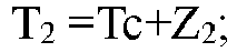
- Where, T2 is the parameter substitution value corresponding to the temperature value at the refrigerant inlet, TC is the high-voltage saturation temperature, and Z2 is the second preset difference value.
- It can be understood that during the operation of the heating mode, the compressor will continue to be operated in the preset operation state, that is, variation ranges of the pressure value and the temperature value of the refrigerant output by the compressor are relatively small. Thus, only when the fault parameter value is determined as the temperature value at the refrigerant inlet, the operation of the air conditioner is continuously controlled according to the parameter substitution value calculated by the high-voltage saturation temperature and the second preset difference value, the parameter substitution value does not need to be frequently updated.
- In any one of the aforesaid technical solutions, the second temperature sensor is in the fault state, the number of the indoor units is at least two, and the step of obtaining the parameter substitution value corresponding to the fault parameter value according to the operating parameters of the air conditioner specifically includes: determining the fault parameter value as the temperature value at the refrigerant outlet on the basis that the air conditioner is in the refrigeration mode, and obtaining the number of indoor units in operation state in the air conditioner; obtaining temperature values at refrigerant inlets, the target superheat degrees, preset amount of heat output, temperatures of exhaust air and target superheat degrees of exhaust air of compressors of the at least two indoor units; and determining the parameter substitution value corresponding to the temperature value at the refrigerant outlet according to the number of the indoor units, the temperature values at the refrigerant inlet, the target superheat degrees, the preset amount of heat output, the temperature values of the exhaust air and the target superheat degrees of the exhaust air.
- In this arrangement, the air conditioner is a multi-split air conditioner, that is, the air conditioner includes a plurality of indoor units. The air conditioner is operated in the refrigeration mode, and the refrigerant flows from the first end of the heat exchanger to the second end of the heat exchanger. Since the second temperature sensor is arranged at the second end of the heat exchanger, the temperature parameter value collected by the second temperature sensor is the temperature value at the refrigerant outlet. When the second temperature sensor is in the fault state, the temperature value at the refrigerant outlet may be determined as the fault parameter value.
- When the air conditioner is operated in the refrigeration mode and the temperature value at the refrigerant outlet is the fault parameter value, the number of the started indoor units in the air conditioner needs to be determined, the temperature value at the refrigerant inlet of the air conditioner, the preset amount of heat output and the target superheat degree, and the temperature of the exhaust air of the compressor and the target superheat degree of the exhaust air of the compressor are obtained. The parameter substitution value is estimated through the obtained operating parameters and the number of the started indoor units, and the temperature value at the refrigerant outlet in the collected temperature parameter values is substituted with the parameter substitution value. By controlling the operation of the throttle valve and the draught fan in the indoor unit of the air conditioner using the updated temperature parameter value, a condition that the air conditioner cannot be accurately controlled to be operated in the heating mode due to the inaccurate temperature value at the refrigerant outlet is avoided.
- In any one of the aforesaid technical solutions, the step of determining the parameter substitution value corresponding to the temperature value at the refrigerant outlet specifically includes: calculating a parameter substitution value corresponding to the temperature value at the refrigerant outlet according to the temperature value at the refrigerant inlet and the target superheat degree when determining that the number of indoor units is less than a preset number; calculating the parameter substitution value corresponding to the temperature value at the refrigerant outlet according to the superheat degree of the exhaust air, the temperature of the exhaust air, the temperature at the refrigerant inlet and the target superheat degree when determining that the number of indoor units is greater than or equal to the preset number.
- In this arrangement, when detecting that the number of the started indoor units is less than the preset number, when the parameter substitution value of the temperature value at the refrigerant outlet is calculated, an estimated temperature value at the refrigerant outlet is obtained by calculating according to the temperature value at the refrigerant inlet and the target superheat degree, and the estimated temperature value at the refrigerant outlet is used as the parameter substitution value of the temperature value at the refrigerant outlet.
- The temperature value at the refrigerant outlet is estimated according to the temperature value at the refrigerant inlet and the target superheat degree by using a formula which is expressed as:

- Where, T2 is the parameter substitution value corresponding to the temperature value at the refrigerant outlet, T1 is the temperature value at the refrigerant inlet, and SHS is the target superheat degree.
- In the arrangement, when detecting that the number of the started indoor units is greater than or equal to the preset number, when the parameter substitution value of the temperature value at a refrigerant rear outlet is calculated, the parameter substitution value of the temperature value at the refrigerant outlet is calculated according to the superheat degree of the exhaust air, the temperature value at the refrigerant inlet, the temperature of the exhaust air and the target superheat degree, so that an estimated temperature value at the refrigerant outlet is obtained, and the estimated temperature value at the refrigerant rear outlet is used as the parameter substitution value of the temperature value of the refrigerant rear outlet.
- The temperature value at the refrigerant outlet is estimated according to the superheat degree of the exhaust air, the temperature value at the refrigerant inlet, the temperature of the exhaust air, and the target superheat degree by using a formula, which is expressed as:

- Where, T2 is the parameter substitution value corresponding to the temperature value at the refrigerant outlet, T1 is a temperature value at a refrigerant inlet, SHS is the target superheat degree, and DSHS is the target superheat degrees of the exhaust air, the DSH is the temperature of the exhaust air.
- The parameter substitution value of the temperature value at the refrigerant outlet of the indoor unit having a malfunctioned sensor is obtained by collecting the corresponding parameters of the indoor unit and accurately calculating according to these parameters through the aforesaid formula. Furthermore, the accuracy of controlling the air conditioner to be operated through the parameter substitution value is further improved, and an occurrence of other faults in the operation process of the air conditioner is avoided.
- In any one of the aforesaid technical solutions, the third temperature sensor is in the fault state, the step of obtaining the parameter substitution value corresponding to the fault parameter value according to the operating parameters of the air conditioner specifically includes: determining the fault parameter value as an ambient temperature value; obtaining a temperature value at the refrigerant outlet every third preset time duration; and calculating the parameter substitution value corresponding to the ambient temperature value according to the temperature value at the refrigerant outlet.
- In this arrangement, during the operation of the air conditioner, when the third temperature sensor is in the fault state, the ambient temperature value collected by the third temperature sensor is determined as the fault parameter value. The substitution value of the ambient temperature value may be estimated according to the temperature value at the refrigerant outlet. The estimated ambient temperature value may be obtained by calculating the temperature value at the refrigerant outlet and the third preset difference value, the estimated ambient temperature value is used as the parameter substitution value of the ambient temperature value, and the ambient temperature value in the collected temperature parameter values is replaced by the parameter substitution value. By controlling the operation of the throttle valve and the draught fan in the indoor unit of the air conditioner using the updated temperature parameter value, a condition that the air conditioner cannot be accurately controlled to be operated in the heating mode due to the inaccurate temperature value at the refrigerant inlet is avoided.
- The parameter substitution value of the ambient temperature value is estimated according to the temperature value at the refrigerant outlet by using a formula which is expressed as:

- Where, T3 is the parameter substitution value of the ambient temperature value, T2 is the temperature value at the refrigerant outlet, and Z3 is the third preset difference value.
- It should be noted that, a difference value between the temperature value at the refrigerant outlet and the ambient temperature value when the air conditioner is operated in the refrigeration mode and a difference value between the temperature value at the refrigerant outlet and the ambient temperature value when the air conditioner is operated in the refrigeration mode are different. Thus, different third preset difference values are selected according to different operation modes of the air conditioner before the step of calculating the parameter substitution value of the ambient temperature value.
- It can be understood that, during the operation of the air conditioner, since the ambient temperature value the indoor unit changes continuously, energy losses of the refrigerant and the air in the heat exchanger in a heat exchange process are also variable. Thus, the third preset time duration is set, and the substitution value of the estimated ambient temperature value is updated. The updating method includes: collecting the temperature value at the refrigerant outlet every third preset time duration, and then re-estimating the parameter substitution value of the ambient temperature value according to the temperature value at the refrigerant outlet. The parameter substitution value of the ambient temperature value is continuously updated, the stability of the control of the air conditioner having a sensor fault is further improved.
- In any one of the aforesaid technical solutions, the indoor unit includes a throttle valve, before the step of obtaining the temperature value at the refrigerant outlet of the indoor unit, the method further includes: controlling the throttle valve to stop operation for a fourth preset time duration.
- In this arrangement, when the air conditioner is in operation and the ambient temperature value is the fault parameter value, the temperature value at the refrigerant outlet is collected every third preset time duration, and the parameter substitution value is estimated according to the temperature value at the refrigerant outlet. Before each time the temperature value at the refrigerant outlet is collected, the throttle valve is controlled to stope operation for the fourth preset time duration. It can be understood that when the throttle valve is in an open state, the low-temperature or high-temperature refrigerant continues to flow into the heat exchanger, and a great difference between the temperature value at the refrigerant outlet and the ambient temperature value is caused. Thus, before the temperature value at the refrigerant outlet is collected, the throttle valve is controlled to stop operation for the fourth preset time duration, the difference between the temperature value at the refrigerant outlet and the ambient temperature value may be reduced, and the accuracy of the estimated parameter substitution value of the temperature value at the refrigerant inlet is further improved.
- In any one of the aforesaid technical solutions, the step of determining the fault states of the first temperature sensor, the second temperature sensor and the third temperature sensor includes: obtaining a numerical relationship between the temperature value at the refrigerant inlet, the temperature value at the refrigerant outlet and the ambient temperature value; and determining the fault state of the first temperature sensor, the fault state of the second temperature sensor and the fault state of the third temperature sensor respectively according to the numerical relationship.
- In this arrangement, whether there exists one malfunctioned temperature sensor in the three temperature sensors is detected according to a data relationship between the temperature parameter value collected by the first temperature sensor, the temperature parameter value collected by the second temperature sensor and the temperature parameter value collected by the third temperature sensor, and the malfunctioned temperature sensor in the three temperature sensors may be located.
- In any one of the aforesaid technical solutions, the method for controlling the air conditioner further includes: counting a time duration of an operation process of the air conditioner controlled according to the parameter substitution value; and controlling the air conditioner to stop operation when determining that the time duration reaches a fourth preset time duration.
- In this arrangement, after time duration of the operation process of the air conditioner controlled according to the estimated temperature parameter value reaches the fourth preset time duration, the air conditioner is controlled to stop operation. Since the parameter substitution value of the temperature parameter value is the estimated temperature parameter value, there is a certain difference between the parameter substitution value of the temperature parameter value and a true value of the temperature parameter value. After the time duration of the operation of the air conditioner controlled according to the estimated temperature parameter value reaches the fourth time duration, the air conditioner is controlled to stop operation. Thus, the air conditioner may be prevented from being operated under a fault state of one temperature sensor for a long time. The stability of operation of the air conditioner is improved.
- An apparatus for controlling an air conditioner is provided according to the second aspect of the present application, this apparatus includes: a fault parameter acquisition unit configured to acquire a fault parameter value in at least two temperature parameter values on the basis that any one of the at least two temperature sensors is in a fault state; a parameter determination unit configured to obtain a parameter substitution value corresponding to the fault parameter value according to operating parameters of the air conditioner; and an operation control unit configured to control the air conditioner to be operated according to the parameter substitution value.
- The apparatus for controlling the air conditioner provided in the present application is used for controlling the air conditioner, one indoor unit and a plurality of temperature sensors are arranged in the air conditioner, the plurality of temperature sensors are provided at different positions of the indoor unit, and the plurality of temperature sensors may respectively collect temperature parameter values at the different positions. A throttle valve and a draught fan are further provided in the indoor unit, and the throttle valve and the draught fan of the indoor unit are controlled according to the plurality of corresponding temperature parameter values collected by the plurality of temperature sensors, and a control of operation of the indoor unit is realized.
- The indoor unit of the air conditioner collects the temperature parameter values continuously through the plurality of temperature sensors, and collects the operating parameters of the air conditioner continuously, and controls the operation of the air conditioner according to the collected temperature parameter values and the collected operating parameters. Where, the throttle valve and the draught fan in the indoor unit are controlled through the temperature parameter values collected by the temperature sensors.
- Whether there exists malfunctioned temperature sensor(s) arranged in the indoor unit is detected during the operation of the air conditioner. When detecting that at least two temperature sensors are in the fault state, a fault sensor in the plurality of temperature sensors is detected and located. Thus, the fault parameter value in the temperature parameter values collected by the plurality of temperature sensors may be determined, and the true value of the fault parameter value is estimated through other operating parameters of the air conditioner and the parameter substitution value is obtained. The plurality of collected temperature parameter values is updated by replacing the fault parameter value in the plurality of temperature parameter values with the parameter substitution value. The operation of the air conditioner is continued to be controlled through the parameter substitution value, such that the indoor unit of the air conditioner can still keep operation under the condition that the temperature sensor in the indoor unit of the air conditioner are in the fault state. It is ensured that the air conditioner can still be operated in a queueing process for maintenance, a downtime of the air conditioner in the queueing process for maintenance is shortened. Thus, a user experience is improved.
- According to the third aspect of the present application, an air conditioner is provided. The air conditioner includes: an indoor unit; and the apparatus for controlling the air conditioner according to the second aspect, the apparatus is arranged in the indoor unit.
- The air conditioner provided in the present application includes the indoor unit and the apparatus for controlling the air conditioner. The apparatus for controlling the air conditioner is the device for controlling the air conditioner in the second aspect and thus has all of the beneficial effects of the apparatus for controlling the air conditioner in the second aspect, which are not repeatedly described herein.
- The air conditioner further includes an outdoor unit and a refrigerant pipeline, and the outdoor unit is connected to the indoor unit through the refrigerant pipeline.
- An air conditioner is provided according to the fourth aspect of the present application, the air conditioner includes: at least two indoor units; a memory; and a processor. The memory stores a program or an instruction, the processor is configured to execute the program or the instruction stored in the memory so as to implement steps of the method for controlling the air conditioner in the first aspect, and thus has all of the beneficial effects of the method for controlling the air conditioner in the first aspect, which are not repeatedly described herein.
- The air conditioner provided in the present application includes at least two indoor units, a memory, and a processor. A program or an instruction is stored in the memory; and the processor is configured to execute the program or the instruction stored in the memory to implement the steps of the method for controlling the air conditioner in the first aspect, and thus has all of the beneficial effects of the method for controlling the air conditioner in the first aspect, which are not repeatedly described herein.
- The air conditioner further includes an outdoor unit and a refrigerant pipeline, and the outdoor unit is connected to the at least two indoor units through the refrigerant pipeline.
- A readable storage medium is provided according to the fifth aspect of the present application, the readable storage medium stores a program or an instruction. When the program or the instruction is executed by the processor, the steps of the method for controlling the air conditioner in any one of the aforesaid possible arrangements are implemented. Thus, the storage medium has all of the beneficial technical effects of the method for controlling the air conditioner in any possible arrangement, which are not repeatedly described herein.
- Additional aspects and advantages of the present application will become apparent in the following descriptions or be understood through the practice of the present application.
- The aforesaid and/or additional aspects and advantages of the present application will become apparent and more understandable in the following description of embodiments with reference to the drawings. Where:
-
FIG. 1 illustrates a first schematic flow diagram of a method for controlling an air conditioner according to the first embodiment of the present application; -
FIG. 2 illustrates a schematic structural diagram of an indoor unit of the air conditioner in the first embodiment of the present application; -
FIG. 3 illustrates a second schematic flow diagram of the method for controlling the air conditioner according to the first embodiment of the present application; -
FIG. 4 illustrates a third schematic flow diagram of the method for controlling the air conditioner according to the first embodiment of the present application; -
FIG. 5 illustrates a fourth schematic flow diagram of the method for controlling the air conditioner according to the first embodiment of the present application; -
FIG. 6 illustrates a fifth schematic flow diagram of the method for controlling the air conditioner according to the first embodiment of the present application; -
FIG. 7 illustrates a sixth schematic flow diagram of the method for controlling the air conditioner according to the first embodiment of the present application; -
FIG. 8 illustrates a seventh schematic flow diagram of the method for controlling the air conditioner according to the first embodiment of the present application; -
FIG. 9 illustrates an eighth schematic flow diagram of the method for controlling the air conditioner according to the first embodiment of the present application; -
FIG. 10 illustrates a ninth schematic flow diagram of the method for controlling the air conditioner according to the first embodiment of the present application; -
FIG. 11 illustrates a tenth schematic flow diagram of the method for controlling the air conditioner according to the first embodiment of the present application; -
FIG. 12 illustrates an eleventh schematic block diagram of the method for controlling the air conditioner according to the first embodiment of the present application; -
FIG. 13 illustrates a twelfth schematic block diagram of the method for controlling the air conditioner according to the first embodiment of the present application; -
FIG. 14 illustrates an apparatus for controlling an air conditioner according to the second embodiment of the present application; -
FIG. 15 illustrates a schematic block diagram of an air conditioner according to the third embodiment of the present application; -
FIG. 16 illustrates a schematic block diagram of an air conditioner according to the fourth embodiment of the present application. - Where, a correspondence relationship between reference numerals and names of components in
FIG. 2 are listed below:
200 indoor unit, 202 heat exchanger, 204 first temperature sensor, 206 second temperature sensor, 208 third temperature sensor. - In order to understand the objective, the features and the beneficial effects of the present application more clearly, the present is further described in detail below with reference to the accompanying figures and the detailed description of embodiments. It is worth noting that, the various embodiments and the features in the various embodiments can be combined mutually without confliction.
- Many details have been illustrated in the following description in order to facilitate a comprehensive understanding of the present application. However, the present application may also be implemented in other manners different from the manners described herein. Thus, the protection scope of the present application is not limited to the embodiments disclosed hereinafter.
- As shown in
FIG. 1 , a method for controlling an air conditioner is provided in the first embodiment of the present application, the air conditioner includes at least two temperature sensors and an indoor unit. The at least two temperature sensors may collect at least two temperature parameter values in the indoor unit, the at least two temperature parameter values correspond to the at least two temperature sensors, and each temperature sensor is configured to collect one temperature parameter value. - The method for controlling the air conditioner includes:
- In a step of S102, any one of the at least two temperature sensors is determined as being in a fault state;
- In a step of S104, a fault parameter value in the at least two temperature parameter values is determined.
- In a step of S106, a parameter substitution value is estimated through operating parameters of the air conditioner.
- In a step of S108, an operation of the air conditioner is controlled through the parameter substitution value.
- Where, the parameter substitution value corresponds to the fault parameter value.
- The air conditioner provided in this embodiment is used for controlling the air conditioner, indoor unit(s) and a plurality of temperature sensors are provided in the air conditioner. The plurality of temperature sensors are located at different positions of the indoor unit. The plurality of temperature sensors may collect temperature parameter values at different positions respectively. A throttle valve and a draught fan are further provided in the indoor unit, the throttle valve and the draught fan of the indoor unit are controlled according to the plurality of corresponding temperature parameter values collected by the plurality of temperature sensors. Thus, the control of the operation of the indoor unit is realized.
- The indoor unit of the air conditioner collects the temperature parameter values continuously through the plurality of temperature sensors, and collects the operating parameters of the air conditioner continuously, and controls the operation of the air conditioner according to the collected temperature parameter values and the operating parameters. Where, the throttle valve and the draught fan in the indoor unit are controlled through the temperature parameter values collected by the temperature sensors.
- Whether there exists a malfunctioned temperature sensor in the indoor unit is detected during the operation of the air conditioner. When detecting that there exists at least two malfunctioned temperature sensors, the malfunctioned sensors in the plurality of temperature sensors are detected and located. Thus, the fault parameter values in the temperature parameter values collected by the plurality of temperature sensors may be determined, and the true value of the fault parameter value is estimated through other operating parameters of the air conditioner, and thus the parameter substitution value is obtained. The fault parameter value in the plurality of temperature parameter values is substituted with the parameter substitution value, and updating of the plurality of collected temperature parameter values is realized. The operation of the air conditioner is continued to be controlled through the parameter substitution value. The indoor unit of the air conditioner can still keep operation under the condition that there exists a malfunctioned temperature sensor in the indoor unit of the air conditioner. It is guaranteed that the air conditioner can still be operated in the queueing process for maintenance, a downtime of the air conditioner in the queueing process for maintenance is shortened, and a usage experience of a user is improved.
- In some embodiments, when detecting that there exists malfunctioned temperature sensor(s) in the air conditioner, the air conditioner outputs corresponding prompt information for prompting fault(s) of the temperature sensor(s).
- In some embodiments, after the air conditioner detects that there exists a malfunctioned temperature sensor in the plurality of temperature sensors, after the air conditioner receives an operation instruction from the user, the air conditioner continues to perform the step of estimating the parameter substitution value, and controlling the operation of the air conditioner through the parameter substitution value.
- In these embodiments, the air conditioner may determine whether continuous operation needs to performed according to the actual requirement of the user. If the air conditioner fails to receive the operation instruction from the user, the air conditioner is controlled to stop operation after outputting prompt information of "fault and halt". A controllability of the air conditioner is improved, and the air conditioner may select to continue to be operated or stop operation according to the requirement of the user when temperature sensor(s) is/are in the fault state.
- As shown in
FIG. 2 , in any one of the aforesaid embodiments, aheat exchanger 202 is arranged in theindoor unit 200, the temperature sensors includes afirst temperature sensor 204, asecond temperature sensor 206, and athird temperature sensor 208. Thefirst temperature sensor 204 and thesecond temperature sensor 206 are arranged at two ends of theheat exchanger 202, thethird temperature sensor 208 is arranged at an air inlet of theindoor unit 200. - In this embodiment, the
indoor unit 200 of the air conditioner includes theheat exchanger 202, when the air conditioner is operated in a refrigeration mode, refrigerant flows to a second end through a first end of theheat exchanger 202. When the air conditioner is operated in a heating mode, the refrigerant flows to the first end through the second end of theheat exchanger 202. A plurality of temperature sensors are further arranged in theindoor unit 200. The plurality of temperature sensors include thefirst temperature sensor 204 arranged at the first end of theheat exchanger 202. Thefirst temperature sensor 204 may collect a temperature value at the refrigerant inlet of theindoor unit 200 under a refrigeration mode. Thefirst temperature sensor 204 may collect a temperature value at a refrigerant outlet of theindoor unit 200 under a heating mode. The plurality of temperature sensors further include thesecond temperature sensor 206 arranged at the second end of theheat exchanger 202, thesecond temperature sensor 206 may detect a temperature value at a refrigerant outlet of theindoor unit 200 in the refrigeration mode. Thesecond temperature sensor 206 may collect a temperature value at the refrigerant inlet of theindoor unit 200 under the heating mode. The plurality of temperature sensors further include athird temperature sensor 208 arranged at the air inlet of theindoor unit 200, and thethird temperature sensor 208 may collect the temperature of the air entering theindoor unit 200. That is, thethird temperature sensor 208 may collect the ambient temperature value of theindoor unit 200. - As shown in
FIG. 3 , in any one of the aforesaid embodiments, the step of determining the fault parameter value in the at least two temperature parameter values specifically includes:
In a step of S302, a fault state of the first temperature sensor, a fault state of the second temperature sensor, and a fault state of the third temperature sensor are detected respectively. - In a step of S304, a corresponding fault parameter value is determined according to the fault state of the first temperature sensor, the fault state of the second temperature sensor, and the fault state of the third temperature sensor.
- Where, the fault parameter value includes a temperature value at the refrigerant inlet, a temperature value at the refrigerant outlet, and an ambient temperature value.
- In this embodiment, the indoor unit of the air conditioner is provided with a throttle valve and a draught fan, during the operation of the indoor unit, the operation of the indoor unit is controlled by controlling parameters such as an opening degree of the throttle valve and a rotation speed of the draught fan. The detail of the control method includes: adjusting the opening degree of the throttle valve according to the collected temperature value at the refrigerant outlet, the ambient temperature value, and the temperature value at the refrigerant inlet, and adjusting the rotation speed of the draught fan.
- Whether there exists a fault parameter value in the plurality of temperature parameter values is determined by determining whether each of the plurality of temperature sensors in the indoor unit of the air conditioner malfunctions. When a malfunctioned temperature sensor in the plurality of temperature sensors is detected, it is determined that a fault parameter value is included in the collected multiple temperature parameter values. The fault parameter value in the temperature parameter values collected by the three temperature sensors may be determined by determining whether the three temperature sensors malfunction respectively, under the determination of the operation mode of the air conditioner. Thus, the fault parameter value in the collected temperature parameter values is determined rapidly when there exists a malfunctioned temperature sensor in the indoor unit, and the air conditioner is prevented from being continuously controlled according to the fault parameter value, the duration of operation of the air conditioner in the fault state is reduced.
- As shown in
FIG. 4 , in any one of the aforesaid embodiments, before estimating the parameter substitution value through the operating parameters of the air conditioner, the method includes:
In a step of S402, the air conditioner is controlled to be operated in a preset operation mode. - In a step of S404, operating parameters of the air conditioner are collected in the preset operation mode.
- The preset operation mode includes a refrigeration mode and a heating mode.
- In this embodiment, since the control parameters and the operating parameters of the air conditioner operated in the refrigeration mode and the control parameters and the operating parameters of the air conditioner operated in the heating mode are different, flow directions of the refrigerant flowing through the heat exchanger of the indoor unit are also different when the air conditioner is operated in different modes. Thus, the temperature parameter values collected by the first temperature sensor and the second temperature sensor are also different. The current operation mode of the air conditioner needs to be determined before estimating the parameter substitution value, the fault parameter value is determined according to the operation mode and whether each temperature sensor in the plurality of temperature sensors malfunctions. The corresponding operating parameters are collected in the process of operating the air conditioner in the preset operation mode, then, the parameter substitution value is estimated through the collected operating parameters. Thus, the calculated parameter substitution value is consistent with the operation mode of the air conditioner, an accuracy of operation of the air conditioner according to the parameter substitution value is improved, and a malfunction of the air conditioner caused due to the control of the air conditioner according to the parameter substitution value that does not conform to the operation mode is avoided.
- It can be understood that the operation mode of the air conditioner further includes an air supplying mode, when the air conditioner is in the air supplying mode, a compressor of the air conditioner does not need to be operated, and a cut-off valve in the indoor unit does not need to be started, either. Thus, the malfunction of the temperature sensor does not affect air supplying operation of the air conditioner, and thus the corresponding parameter substitution value does not need to be estimated.
- In some embodiments, a fault of the first temperature sensor of the air conditioner is detected. In the refrigeration mode, since the temperature parameter value collected by the first temperature sensor is the temperature value at the refrigerant inlet, the temperature value at the refrigerant inlet in the collected temperature parameter values is determined as the fault parameter value. In the heating mode, since the temperature parameter value collected by the first temperature sensor is the temperature value at the refrigerant outlet, the temperature value at the refrigerant outlet in the collected temperature parameter values is determined as the fault parameter value.
- In some other embodiments, a fault of the second temperature sensor of the air conditioner is detected. In the refrigeration mode, since the temperature parameter value collected by the second temperature sensor is the temperature value at the refrigerant outlet, the temperature value at the refrigerant outlet in the collected temperature parameter values is determined as the fault parameter value. In the heating mode, since the temperature parameter value collected by the second temperature sensor is the temperature value at the refrigerant inlet, the temperature value at the refrigerant inlet in the collected temperature parameter values is determined as the fault parameter value.
- In some other embodiments, a fault of the third temperature sensor of the air conditioner is detected. Since the temperature parameter value collected by the third temperature sensor is the ambient temperature value, the ambient temperature value in the collected temperature parameter values is determined as the fault parameter value.
- As shown in
FIG. 5 , in any one of the aforesaid embodiments, the fault in the first temperature sensor is determined, and the air conditioner includes a plurality of indoor units. The step of estimating the parameter substitution value through the operating parameters of the air conditioner specifically includes: - In a step of S502, the temperature value at the refrigerant outlet is determined as the fault parameter value according to the operation of the air conditioner in the heating mode.
- In a step of S504, the number of the indoor units in the operating state is determined.
- In a step of S506, a preset amount of heat output, a pressure value at the refrigerant outlet, a target subcooling degree, and a high-pressure saturation temperature.
- In a step of S508, the parameter substitution value of the temperature value at the refrigerant outlet is estimated according to the preset amount of heat output, the pressure value at the refrigerant outlet, the target subcooling degree and the high-pressure saturation temperature.
- In this embodiment, the air conditioner is a multi-split air conditioner, that is, the air conditioner includes a plurality of indoor units. The air conditioner is operated according to the heating mode, and the high-temperature and high-pressure refrigerant generated by the compressor flows to the first end of the heat exchanger of the indoor unit through the second end of the heat exchanger of the indoor unit. Since the first temperature sensor is arranged at the first end of the heat exchanger, the temperature parameter value collected by the first temperature sensor is the temperature value at the refrigerant outlet. When the first temperature sensor is in a fault state, the temperature value at the refrigerant outlet may be determined as the fault parameter value.
- When the air conditioner is operated in the heating mode and the temperature value at the refrigerant outlet is the fault parameter value, the number of the started indoor units in the air conditioner needs to be determined, and the operating parameters including the high-pressure saturation temperature of the air conditioner, the preset amount of heat output, the pressure value at the refrigerant outlet, the target subcooling degree of the indoor unit are obtained. The parameter substitution value is estimated through the obtained operating parameters and the number of the indoor unit in operation, and the temperature value at the refrigerant outlet in the collected temperature parameter values is substituted with the parameter substitution value. By controlling the operation of the throttle valve and the draught fan in the indoor unit of the air conditioner using the updated temperature parameter value, a condition that the air conditioner cannot be accurately controlled to be operated in the heating mode due to inaccurate temperature value at the refrigerant outlet may be avoided.
- It is worth noting that, the high-voltage saturation temperature is the hardware parameter of the air conditioner system. Thus, when the parameter substitution value is calculated, the high-voltage protection temperature of the system may be directly invoked. The target subcooling degree is the parameter value obtained through calculation according to an operation instruction after the operation instruction is received by the air conditioner. The pressure value at the refrigerant outlet may be directly collected by arranging the pressure sensors. As an alternative, the pressure value at the refrigerant outlet may be calculated through other parameter values such as the temperature at the refrigerant outlet. The preset heat output may be calculated according to the high-pressure saturation temperature and the ambient environment.
- As shown in
FIG. 6 , in any one of the aforesaid embodiments, the step of estimating the parameter substitution value of the temperature value at the refrigerant outlet specifically includes: - In a step of S602, it is determined that the air conditioner is operated in a heating mode.
- In a step of S604, whether the number of indoor units is less than a preset number is determined; if the number of the indoor units is less than the preset number, a step of S606 is performed; if the number of the indoor units is equal to or greater than the preset number, a step of S608 is performed.
- In the step of S606, the parameter substitution value of the temperature value at the refrigerant outlet is estimated according to the target subcooling degree and the high-pressure saturation temperature.
- In the step of S608, the parameter substitution value of the temperature value at the refrigerant outlet is estimated according to the preset amount of heat output and the pressure value at the refrigerant outlet.
- In this embodiment, if it is detected that the number of started indoor units is less than the preset number, when the parameter substitution value of the temperature value at the refrigerant outlet is calculated, the parameter substitution value of the temperature value at the refrigerant outlet is obtained by calculating the difference value between the high-voltage saturation temperature and the target subcooling degree, and the estimated temperature value at the refrigerant outlet is used as the parameter substitution value of the temperature value at the refrigerant outlet.
- The temperature value at the refrigerant outlet is estimated according to the target subcooling degree and the pressure saturation temperature by using a formula which is expressed as:

- Where, T1 is the parameter substitution value corresponding to the temperature value at the refrigerant outlet, TC is the high-voltage saturation temperature, and the SCS is the target subcooling degree.
- In this embodiment, if it is detected that the number of the started indoor units is greater than or equal to the preset number, whether the temperature sensor in each indoor unit malfunctions is detected. If a fault-free indoor unit is detected, a pressure value at the refrigerant outlet of an indoor unit without sensor fault is calculated, and a pressure value at the refrigerant outlet of an indoor unit having a sensor fault is calculated, the preset amount of heat output is obtained according to the two pressure values at the refrigerant outlet, enthalpy value of the refrigerant outlet of the heat exchanger is calculated according to the preset amount of heat output, and the temperature value at the refrigerant outlet is estimated according to the enthalpy value of the refrigerant outlet, and the parameter substitution value corresponding to the temperature value at the refrigerant outlet is calculated accordingly.
- The pressure value at the refrigerant outlet of the indoor unit without sensor fault is calculated through the formula which is expressed as:

- Where, P1 is the pressure value at the refrigerant outlet of the indoor unit without sensor fault, PC is the maximum pressure value of an outdoor unit, and dP1 is a pressure drop across an electronic expansion valve of the indoor unit without sensor fault.
- It can be understood that, the pressure drop across the electronic expansion valve of the indoor unit without sensor fault may be calculated by calculating the pressure values at the two ends of the electronic expansion valve collected by the sensors. The pressure drop may also be obtained by calculation according to a refrigerant flow value, the enthalpy value of the refrigerant outlet, and the preset amount of heat output of the indoor unit.
- The pressure value at the refrigerant outlet of the indoor unit having a sensor fault is calculated through a formula which is expressed as:

- H1 is a liquid column pressure value caused due to height difference between a malfunctioned indoor unit and a reference point, Hz is the liquid column pressure value caused due to height difference between the indoor unit having a sensor fault and the reference point, den is a density of the refrigerant of the malfunctioned indoor unit, P2 is the pressure value at the refrigerant outlet of the malfunctioned indoor unit, and P1 is the pressure value at the refrigerant outlet of the indoor unit without sensor fault.
- It can be understood that, the liquid column pressure value caused due to the height difference between the indoor unit and the reference point is calculated during a trial operation stage of the air conditioner. The density of the refrigerant may be obtained by calculating a physical property function of the liquid refrigerant, and a segmented fitting curve may be adopted in the process of calculation of the density of the refrigerant.
- A refrigerant flow value is calculated through a formula, which is expressed as:

- Where, mf is the refrigerant flow value, dP2 is the pressure drop across the electronic expansion valve of the indoor unit having a sensor fault, cv is an opening value of the electronic expansion valve, and den is the density of the refrigerant of the malfunctioned indoor unit.
- The pressure drop across the electronic expansion valve of the indoor unit having a sensor fault is calculated through a formula, which is expressed as:

- dp2 is the pressure drop across the electronic expansion valve of the indoor unit having a sensor fault, PC is the maximum pressure value of the outdoor unit, and P2 is the pressure value at the refrigerant outlet of the malfunctioned indoor unit.
- The preset heat output is calculated through a formula, which is expressed as:

- Where, Q is the preset amount of heat output, KA is a coefficient, TC is the high-voltage saturation temperature, and T3 is the ambient temperature value.
- The enthalpy value of the refrigerant outlet of the heat exchanger is calculated through a formula according to the preset amount of heat output, the formula is expressed as:

- H1 is an enthalpy value of the refrigerant outlet, H2 is an enthalpy value at the refrigerant inlet, Q is a preset amount of heat output, and mf is the refrigerant flow value.
- The parameter substitution value of the temperature value at the refrigerant outlet is calculated according to the enthalpy value of the refrigerant outlet by using the following formula. :

- Where, T1 is the parameter substitution value corresponding to the temperature value at the refrigerant outlet, hi is the enthalpy value of the refrigerant outlet, TC is the high-voltage saturation temperature, and f1 is a preset function.
- According to the aforesaid formula, the parameter substitution value of the temperature value at the refrigerant outlet of the indoor unit having a sensor fault is accurately obtained by collecting corresponding parameters of the indoor unit without sensor fault and calculating according to the corresponding parameters, under the condition that a plurality of indoor units are powered on. The accuracy of operation of the air conditioner controlled according to the parameter substitution value is further improved, and occurrence of other faults during the operation process of the air conditioner is avoided.
- In some embodiments, a value range of the preset number is greater than or equal to 2.
- In these embodiments, when the number of started indoor units in the air conditioner is greater than or equal to 2, and the started indoor units includes indoor units having fault-free sensor(s), the parameter substitution value of the temperature value at the refrigerant outlet of the indoor unit having sensor fault is calculated by collecting corresponding parameters of the indoor unit having the fault-free sensor(s).
- It may be understood that, when the preset number is selected to be greater than 2, the parameter substitution value of the temperature value at the refrigerant outlet of the indoor unit having a plurality of malfunctioned sensors may be calculated by collecting corresponding parameters of one indoor unit without sensor fault, the control of the operation of the indoor unit having the plurality of malfunctioned sensors in the air conditioner is realized, and the inconvenience caused due to termination of operation of the air conditioner is avoided.
- As shown in
FIG. 7 , in any one of the aforesaid embodiments, the first temperature sensor is in the fault state, the step of estimating the parameter substitution value through the operating parameters of the air conditioner specifically includes: - In a step of S702, the temperature value at the refrigerant inlet is determined as the fault parameter value according to the operation of the air conditioner in the refrigeration mode.
- In a step of S704, the draught fan is controlled to stop operation for a second preset time duration every first preset time duration, and the temperature value at the refrigerant outlet is collected.
- In a step of S706, the parameter substitution value of the temperature value at the refrigerant inlet is estimated according to the temperature value at the refrigerant outlet.
- In this embodiment, the air conditioner is a multi-split air conditioner, that is, the air conditioner includes a plurality of indoor units. The air conditioner is operated in the refrigeration mode, and the refrigerant flows from the first end of the heat exchanger to the second end of the heat exchanger. Since the first temperature sensor is arranged at the first end of the heat exchanger, the temperature parameter value collected by the first temperature sensor is the temperature value at the refrigerant inlet. When the first temperature sensor is in the fault state, the temperature value at the refrigerant inlet may be determined as the fault parameter value.
- When the air conditioner is operated in the refrigeration mode and the temperature value at the refrigerant inlet is the fault parameter value. A substitution value of the temperature value at the refrigerant inlet may be estimated according to the temperature value at the refrigerant outlet. In the refrigerant mode, the low-temperature refrigerant flows to the second end of the heat exchanger of the indoor unit through the first end of the heat exchanger of the indoor unit. During the process in which the refrigerant flows through the heat exchanger, the low-temperature refrigerant continuously exchanges heat with ambient air. Therefore, the temperature value at the refrigerant outlet should be higher than the temperature value at the refrigerant inlet, the difference value between the temperature value at the refrigerant outlet and the first preset difference value is calculated, and the estimated temperature value at the refrigerant inlet may be obtained, the estimated temperature value at the refrigerant inlet is used as the parameter substitution value of the temperature value at the refrigerant inlet, and the temperature value at the refrigerant inlet in the collected temperature parameter values is substituted with the parameter substitution value. By controlling the operation of the throttle valve and the draught fan in the indoor unit of the air conditioner using the updated temperature parameter value, a condition that the air conditioner cannot be accurately controlled to be operated in the heating mode due to the inaccurate temperature value at the refrigerant inlet is avoided.
- The parameter substitution value of the temperature value at the refrigerant inlet is estimated according to the temperature value at the refrigerant outlet by using a formula which is expressed as:

- Where, T1 represents the parameter substitution value corresponding to the temperature value at the refrigerant inlet, T2 represents the temperature value at the refrigerant outlet, Z1 represents the first preset difference value.
- It can be understood that, in the operation process of the air conditioner in the refrigeration mode, since the ambient temperature value of the indoor unit changes continuously, energy losses of the refrigerant and the air in the heat exchanger in the heat exchange process are also variable. Thus, the estimated parameter substitution value of the refrigerant inlet is updated every first preset time duration. The updating method includes: collecting the temperature value at the refrigerant outlet every first preset time duration, and then re-estimating the parameter substitution value of the temperature value at the refrigerant inlet according to the temperature value at the refrigerant outlet. The parameter substitution value of the temperature value at the refrigerant inlet is continuously updated, the stability of the control of the air conditioner having a sensor fault is further improved.
- When the air conditioner is operated in the refrigeration mode and the temperature value at the refrigerant inlet is the fault parameter value, the temperature value at the refrigerant outlet is collected every first preset time duration, and the parameter substitution value is estimated according to the temperature value at the refrigerant outlet. Before each time the temperature value at the refrigerant outlet is collected, the draught fan is controlled to stop operation for a second preset time duration. It can be understood that the operation of the draught fan may accelerate the heat exchange between the heat exchanger and ambient air. Thus, before the collection of the temperature value at the refrigerant outlet, the draught fan is controlled to stop operation for the second preset time duration, the value of energy loss of the refrigerant in the heat exchange process may be decreased, and an accuracy of an estimated parameter substitution value of the temperature value at the refrigerant inlet is further improved.
- In some embodiments, a value range of the second preset time duration is between 10 seconds and 40 seconds.
- In these embodiments, the value of the second preset time duration is set to be greater than or equal to 10 seconds, such that there is enough time for the temperature value at the refrigerant outlet to approach the temperature value at the refrigerant inlet. The value of the second preset time duration is set to be less than or equal to 40 seconds, such that a malfunction of air conditioner caused due to long time of poor heat exchange of refrigerant in the heat exchanger may be avoided.
- As shown in
FIG. 8 , in any one of the aforesaid embodiments, the second temperature sensor is in the fault state, and the step of estimating the parameter substitution value through the operating parameters of the air conditioner specifically includes: - In a step of S802, the temperature value at the refrigerant inlet is determined as the fault parameter value according to the operation of the air conditioner in the heating mode.
- In a step of S804, a high-voltage saturation temperature is obtained.
- In a step of S806, the parameter substitution value of the temperature value at the refrigerant inlet is estimated according to the high-pressure saturation temperature.
- In this embodiment, the air conditioner is a multi-split air conditioner, that is, the air conditioner includes a plurality of indoor units. The air conditioner is operated in the heating mode, the high-temperature and high-pressure refrigerant generated by the compressor flows to the first end of the heat exchanger of the indoor unit through the second end of the heat exchanger of the indoor unit. Since the first temperature sensor is arranged at the first end of the heat exchanger, the temperature parameter value collected by the first temperature sensor is the temperature value at the refrigerant outlet. When the first temperature sensor is in the fault state, the temperature value at the refrigerant outlet may be determined as the fault parameter value.
- When the air conditioner is operated in the heating mode and the temperature value at the refrigerant inlet is the fault parameter value, the substitution value of the temperature value at the refrigerant inlet may be estimated according to the high-pressure saturation temperature. In the heating mode, the high-temperature refrigerant compressed by the compressor directly flows to the second end of the heat exchanger, thus, the parameter substitution value of the relatively accurate temperature value at the refrigerant inlet may be obtained by estimating according to hardware parameters of the air conditioning system. The high-pressure saturation temperature is the temperature value corresponding to the refrigerant under a certain pressure, it may be considered that the high-pressure saturation temperature is the temperature value of the high-pressure and high-temperature refrigerant output by the compressor, the high-temperature and high-pressure refrigerant flows to the second end of the heat exchanger of the indoor unit through a refrigerant pipeline, and certain heat loss is caused. The second preset difference value is arranged according to heat loss. The temperature value at the refrigerant inlet of the heat exchanger in the heating mode may be estimated by calculating the difference value between the high-pressure saturation temperature and the second preset difference value, and the estimated temperature value at the refrigerant inlet is taken as the parameter substitution value of the temperature value at the refrigerant inlet, and the temperature value at the refrigerant inlet in the collected temperature parameter values is substituted with the parameter substitution value. By controlling the operation of the throttle valve and the draught fan in the indoor unit of the air conditioner using the updated temperature parameter value, a condition that the air conditioner cannot be accurately controlled to be operated in the heating mode due to the inaccurate temperature value at the refrigerant inlet is avoided.
- The temperature value at the refrigerant inlet is calculated according to the high-pressure saturation temperature by using a formula which is expressed as:

- Where, T2 is the parameter substitution value corresponding to the temperature value at the refrigerant inlet, TC is the high-voltage saturation temperature, and Z2 is the second preset difference value.
- It can be understood that, during the operation of the heating mode, the compressor will continue to be operated in the preset operation state, that is, variation ranges of the pressure value and the temperature value of the refrigerant output by the compressor are relatively small. Thus, only when the fault parameter value is determined as the temperature value at the refrigerant inlet, the operation of the air conditioner is continuously controlled according to the parameter substitution value calculated by the high-voltage saturation temperature and the second preset difference value, the parameter substitution value does not need to be frequently updated.
- As shown in
FIG. 9 , in any one of the aforesaid embodiments, the second temperature sensor is in the fault state, and the air conditioner includes a plurality of indoor units. The step of estimating the parameter substitution value according to the operating parameters of the air conditioner specifically includes: - In a step of S902, the temperature value at the refrigerant outlet is determined as the fault parameter value according to the operation of the air conditioner in the refrigeration mode.
- In a step of S904, the number of indoor units in the operation state is determined.
- In a step of S906, the target superheat degree, the temperature value at the refrigerant inlet, the temperature of the exhaust air of the compressor, the preset amount of heat output, and the target superheat degree of the exhaust air of the compressor are collected.
- In a step of S908, the parameter substitution value of the temperature value at the refrigerant outlet is estimated according to the number of indoor units, the target superheat degree, the temperature value at the refrigerant inlet, the temperature of the exhaust air of the compressor, the preset amount of heat output and the target superheat degree of the exhaust air of the compressor.
- In this embodiment, the air conditioner is a multi-split air conditioner, that is, the air conditioner includes a plurality of indoor units. The air conditioner is operated in the refrigeration mode, and the refrigerant flows from the first end of the heat exchanger to the second end of the heat exchanger. Since the second temperature sensor is arranged at the second end of the heat exchanger, the temperature parameter value collected by the second temperature sensor is the temperature value at the refrigerant outlet. When the second temperature sensor is in the fault state, the temperature value at the refrigerant outlet may be determined as the fault parameter value.
- When the air conditioner is operated in the refrigeration mode and the temperature value at the refrigerant outlet is the fault parameter value, the number of the started indoor units in the air conditioner needs to be determined, the temperature value at the refrigerant inlet of the air conditioner, the preset amount of heat output and the target superheat degree, and the temperature of the exhaust air of the compressor and the target superheat degree of the exhaust air of the compressor are obtained. The parameter substitution value is estimated through the obtained operating parameters and the number of the started indoor units, and the temperature value at the refrigerant outlet in the collected temperature parameter values is substituted with the parameter substitution value. By controlling the operation of the throttle valve and the draught fan in the indoor unit of the air conditioner using the updated temperature parameter value, a condition that the air conditioner cannot be accurately controlled to be operated in the heating mode due to the inaccurate temperature value at the refrigerant outlet is avoided.
- As shown in
FIG. 10 , in any one of the aforesaid embodiments, the step of estimating the parameter substitution value of the temperature value at the refrigerant outlet specifically includes: - In a step of
S 1002, operation of the air conditioner in the refrigeration mode is determined. - In a step of
S 1004, whether the number of indoor units is less than a preset number is determined; if the number of indoor units is less than the preset number, a step ofS 1006 is performed, if the number of indoor units is equal to or greater than the preset number, a step of S1008 is performed. - In the step of
S 1006, the parameter substitution value of the temperature value at the refrigerant outlet is estimated according to the target superheat degree and the temperature value at the refrigerant inlet. - In the step of
S 1008, the parameter substitution value of the temperature value at the refrigerant outlet is estimated according to temperature of the exhaust air, the superheat degree of the exhaust air, the target superheat degree, and the temperature at the refrigerant inlet. - In this embodiment, when detecting that the number of the started indoor units is less than the preset number, when the parameter substitution value of the temperature value at the refrigerant outlet is calculated, an estimated temperature value at the refrigerant outlet is obtained by calculating according to the temperature value at the refrigerant inlet and the target superheat degree, and the estimated temperature value at the refrigerant outlet is used as the parameter substitution value of the temperature value at the refrigerant outlet.
- The temperature value at the refrigerant outlet is estimated according to the temperature value at the refrigerant inlet and the target superheat degree by using a formula which is expressed as:

- Where, T2 is the parameter substitution value corresponding to the temperature value at the refrigerant outlet, T1 is the temperature value at the refrigerant inlet, and SHS is the target superheat degree.
- In this embodiment, when detecting that the number of the started indoor units is greater than or equal to the preset number, when the parameter substitution value of the temperature value at a refrigerant rear outlet is calculated, the parameter substitution value of the temperature value at the refrigerant outlet is calculated according to the superheat degree of the exhaust air, the temperature value at the refrigerant inlet, the temperature of the exhaust air and the target superheat degree, so that an estimated temperature value at the refrigerant outlet is obtained, and the estimated temperature value at the refrigerant rear outlet is used as the parameter substitution value of the temperature value of the refrigerant rear outlet.
- The temperature value at the refrigerant outlet is estimated according to the superheat degree of the exhaust air, the temperature value at the refrigerant inlet, the temperature of the exhaust air, and the target superheat degree by using a formula, which is expressed as:

- Where, T2 is the parameter substitution value corresponding to the temperature value at the refrigerant outlet, T1 is a temperature value at a refrigerant inlet, SHS is the target superheat degree, and DSHS is the target superheat degrees of the exhaust air, the DSH is the temperature of the exhaust air.
- The parameter substitution value of the temperature value at the refrigerant outlet of the indoor unit having a malfunctioned sensor is obtained by collecting the corresponding parameters of the indoor unit and accurately calculating according to these parameters through the aforesaid formula. Furthermore, the accuracy of controlling the air conditioner to be operated through the parameter substitution value is further improved, and an occurrence of other faults in the operation process of the air conditioner is avoided.
- As shown in
FIG. 11 , in any one of the aforesaid embodiments, the third temperature sensor is in the fault state, the step of estimating the parameter substitution value according to the operating parameters of the air conditioner specifically includes:
In a step of S1102, an ambient temperature value is determined as the fault parameter value. - In a step of S1104, the throttle valve is controlled to inactivate the fourth preset time duration every third preset time duration and the temperature value at the refrigerant outlet is obtained.
- In a step of
S 1106, the parameter substitution value of the ambient temperature value is estimated according to the temperature value at the refrigerant outlet. - In this embodiment, during the operation of the air conditioner, when the third temperature sensor is in the fault state, the ambient temperature value collected by the third temperature sensor is determined as the fault parameter value. The substitution value of the ambient temperature value may be estimated according to the temperature value at the refrigerant outlet. The estimated ambient temperature value may be obtained by calculating the temperature value at the refrigerant outlet and the third preset difference value, the estimated ambient temperature value is used as the parameter substitution value of the ambient temperature value, and the ambient temperature value in the collected temperature parameter values is replaced by the parameter substitution value. By controlling the operation of the throttle valve and the draught fan in the indoor unit of the air conditioner using the updated temperature parameter value, a condition that the air conditioner cannot be accurately controlled to be operated in the heating mode due to the inaccurate temperature value at the refrigerant inlet is avoided.
- The parameter substitution value of the ambient temperature value is estimated according to the temperature value at the refrigerant outlet by using a formula which is expressed as:

- Where, T3 is the parameter substitution value of the ambient temperature value, T2 is the temperature value at the refrigerant outlet, and Z3 is the third preset difference value.
- It should be noted that, a difference value between the temperature value at the refrigerant outlet and the ambient temperature value when the air conditioner is operated in the refrigeration mode and a difference value between the temperature value at the refrigerant outlet and the ambient temperature value when the air conditioner is operated in the refrigeration mode are different. Thus, different third preset difference values are selected according to different operation modes of the air conditioner before the step of calculating the parameter substitution value of the ambient temperature value.
- It can be understood that, during the operation of the air conditioner, since the ambient temperature value the indoor unit changes continuously, energy losses of the refrigerant and the air in the heat exchanger in a heat exchange process are also variable. Thus, the third preset time duration is set, and the substitution value of the estimated ambient temperature value is updated. The updating method includes: collecting the temperature value at the refrigerant outlet every third preset time duration, and then re-estimating the parameter substitution value of the ambient temperature value according to the temperature value at the refrigerant outlet. The parameter substitution value of the ambient temperature value is continuously updated, the stability of the control of the air conditioner having a sensor fault is further improved.
- In this embodiment, when the air conditioner is in operation and the ambient temperature value is the fault parameter value, the temperature value at the refrigerant outlet is collected every third preset time duration, and the parameter substitution value is estimated according to the temperature value at the refrigerant outlet. Before each time the temperature value at the refrigerant outlet is collected, the throttle valve is controlled to stope operation for the fourth preset time duration. It can be understood that when the throttle valve is in an open state, the low-temperature or high-temperature refrigerant continues to flow into the heat exchanger, and a great difference between the temperature value at the refrigerant outlet and the ambient temperature value is caused. Thus, before the temperature value at the refrigerant outlet is collected, the throttle valve is controlled to stop operation for the fourth preset time duration, the difference between the temperature value at the refrigerant outlet and the ambient temperature value may be reduced, and the accuracy of the estimated parameter substitution value of the temperature value at the refrigerant inlet is further improved.
- In some embodiments, a value range of the fourth preset time duration is between 60 seconds and 120 seconds.
- In these embodiments, the value of the fourth preset time duration is set to be greater than or equal to 60 seconds, thus, there is enough time for the temperature value at the refrigerant outlet for approaching the ambient temperature value. The value of the fourth preset time duration is set to be less than or equal to 120 seconds, such that the malfunction of the air conditioner caused because that the refrigerant cannot enter the heat exchanger of the indoor unit for long time may be avoided.
- As shown in
FIG. 12 , in any one of the aforesaid embodiments, the step of detecting the fault state of the first temperature sensor, the fault state of the second temperature sensor, and the fault state of the third temperature sensor respectively specifically includes: - In a step of 1202, a numerical relationship between the temperature value at the refrigerant inlet, the ambient temperature value, and the temperature value at the refrigerant outlet is determined.
- In a step of 1204, the fault state of each of the temperature sensors is determined according to the numerical relationship.
- In this embodiment, whether there exists a malfunctioned temperature sensor in the three temperature sensors is detected according to the data relationship between the temperature parameter value collected by the first temperature sensor, the temperature parameter value collected by the second temperature sensor and the temperature parameter value collected by the third temperature sensor. Moreover, the malfunctioned temperature sensor in the three temperature sensors may be located.
- In some embodiments, the temperature value at the refrigerant inlet, the ambient temperature value, and the temperature value at the refrigerant outlet are collected, and it is determined that two of the temperature value at the refrigerant inlet, the ambient temperature value and the temperature value at the refrigerant outlet are not fault parameter values.
- When determining that any two temperature parameter values in the three temperature parameter values are non-fault parameter values, whether the other temperature parameter value is determined by the method described below.
- The compressor of the air conditioner stops operation, which lasts for a fifth preset time duration. The other temperature parameter value is determined as the fault parameter value when the following determination conditions are satisfied, the determination conditions are expressed as:

- The air conditioner is operated according to the refrigeration mode. The other temperature parameter value is determined as the fault parameter value when the following determination conditions are satisfied, the determination conditions are expressed as:

- The air conditioner is operated according to the heating mode. The other temperature parameter value is determined as the fault parameter value when the following determination conditions are satisfied, the determination conditions are expressed as:

- Where T1 is the temperature parameter value collected by the first temperature sensor, T2 is the temperature parameter value collected by the second temperature sensor, T3 is the temperature parameter value collected by the third temperature sensor, dT1 is a first preset value, dT2 is a second preset value, dT3 is a third preset value, and dT4 is a fourth preset value.
- As shown in
FIG. 13 , in any one of the aforesaid embodiments, the method for controlling the air conditioner further includes: - In a step of 1302: a time duration of the operation of the air conditioner controlled according to the parameter substitution value is counted.
- In a step of 1304, the air conditioner is controlled to stop operation one the basis that the time duration reaches the fourth preset time duration.
- In this embodiment, after time duration of the operation process of the air conditioner controlled according to the estimated temperature parameter value reaches the fourth preset time duration, the air conditioner is controlled to stop operation. Since the parameter substitution value of the temperature parameter value is the estimated temperature parameter value, there is a certain difference between the parameter substitution value of the temperature parameter value and a true value of the temperature parameter value. After the time duration of the operation of the air conditioner controlled according to the estimated temperature parameter value reaches the fourth time duration, the air conditioner is controlled to stop operation. Thus, the air conditioner may be prevented from being operated under a fault state of one temperature sensor for a long time. The stability of operation of the air conditioner is improved.
- As shown in
FIG. 14 , anapparatus 1400 for controlling an air conditioner is provided the first embodiment of the present application. Theapparatus 1400 includes: - a fault parameter acquisition unit 1402 configured to determine that any one of the at least two temperature sensors is in a fault state, and determine a fault parameter value in at least two temperature parameter values;
- a parameter determination unit 1404 configured to estimate a parameter substitution value according to the operating parameter of the air conditioner;
- an operation control unit 1406 configured to control an operation of the air conditioner according to the parameter substitution value.
- The apparatus for controlling the air conditioner provided in the present application is used for controlling the air conditioner, one indoor unit and a plurality of temperature sensors are arranged in the air conditioner, the plurality of temperature sensors are provided at different positions of the indoor unit, and the plurality of temperature sensors may respectively collect temperature parameter values at the different positions. A throttle valve and a draught fan are further provided in the indoor unit, and the throttle valve and the draught fan of the indoor unit are controlled according to the plurality of corresponding temperature parameter values collected by the plurality of temperature sensors, and a control of operation of the indoor unit is realized.
- The indoor unit of the air conditioner collects the temperature parameter values continuously through the plurality of temperature sensors, and collects the operating parameters of the air conditioner continuously, and controls the operation of the air conditioner according to the collected temperature parameter values and the collected operating parameters. Where, the throttle valve and the draught fan in the indoor unit are controlled through the temperature parameter values collected by the temperature sensors.
- Whether there exists malfunctioned temperature sensor(s) arranged in the indoor unit is detected during the operation of the air conditioner. When detecting that at least two temperature sensors are in the fault state, a fault sensor in the plurality of temperature sensors is detected and located. Thus, the fault parameter value in the temperature parameter values collected by the plurality of temperature sensors may be determined, and the true value of the fault parameter value is estimated through other operating parameters of the air conditioner and the parameter substitution value is obtained. The plurality of collected temperature parameter values is updated by replacing the fault parameter value in the plurality of temperature parameter values with the parameter substitution value. The operation of the air conditioner is continued to be controlled through the parameter substitution value, such that the indoor unit of the air conditioner can still keep operation under the condition that the temperature sensor in the indoor unit of the air conditioner are in the fault state. It is ensured that the air conditioner can still be operated in a queueing process for maintenance, a downtime of the air conditioner in the queueing process for maintenance is shortened. Thus, a use experience of the user is improved.
- In some embodiments, when a malfunctioned temperature sensor in the air conditioner is detected, the air conditioner outputs corresponding prompt information for prompting a fault of the temperature sensor.
- In some embodiments, after the air conditioner detects that there exists a malfunctioned temperature sensor in the plurality of temperature sensors, after the air conditioner receives an operation instruction from the user, the air conditioner continues to perform the step of estimating the parameter substitution value, and controlling the air conditioner to be operated according to the parameter substitution value.
- In these embodiments, the air conditioner may determine whether continuous operation needs to performed according to the actual requirement of the user. If the air conditioner fails to receive the operation instruction from the user, the air conditioner is controlled to stop operation after outputting prompt information of "fault and halt". A controllability of the air conditioner is improved, and the air conditioner may select to continue to be operated or stop operation according to the requirement of the user when temperature sensor(s) is/are in the fault state.
- As shown in
FIG. 2 , in the aforesaid embodiment, aheat exchanger 202 is arranged in theindoor unit 200. The temperature sensor includes afirst temperature sensor 204, asecond temperature sensor 206, and athird temperature sensor 208. Thefirst temperature sensor 204 is arranged at a first end of theheat exchanger 202, thesecond temperature sensor 206 is arranged at a second end of theheat exchanger 202, and thethird temperature sensor 208 is arranged at an air inlet of theindoor unit 200. - In this embodiment, the
indoor unit 200 of the air conditioner includes theheat exchanger 202. When the air conditioner is operated in the refrigeration mode, the refrigerant flows to the second end of theheat exchanger 202 through the first end of theheat exchanger 202. When the air conditioner is operated in the heating mode, the refrigerant flows to the first end of theheat exchanger 202 through the second end of theheat exchanger 202. A plurality of temperature sensors are further arranged in theindoor unit 200. The plurality of temperature sensors include thefirst temperature sensor 204 arranged at the first end of theheat exchanger 202. In the refrigeration mode, thefirst temperature sensor 204 may detect the temperature value at the refrigerant inlet of theindoor unit 200. In the heating mode, thefirst temperature sensor 204 may detect the temperature value at the refrigerant outlet of theindoor unit 200. The plurality of temperature sensors further includes thesecond temperature sensor 206 arranged at the second end of theheat exchanger 202. In the refrigeration mode, thesecond temperature sensor 206 may detect the temperature value at the refrigerant outlet of theindoor unit 200. In the heating mode, thesecond temperature sensor 206 may detect the temperature value at the refrigerant inlet of theindoor unit 200. The plurality of temperature sensors further include thethird temperature sensor 208 arranged at the air inlet of theindoor unit 200, and thethird temperature sensor 208 may detect the temperature of the air entering theindoor unit 200, that is, thethird temperature sensor 208 may detect the ambient temperature value of theindoor unit 200. - As shown in
FIG. 15 , anair conditioner 1500 is provided in the third embodiment of the present application, theair conditioner 1500 includes: anindoor unit 1502 and theapparatus 1400 for controlling the air conditioner. - The
apparatus 1400 for controlling the air conditioner, theapparatus 1400 for controlling the air conditioner is arranged in the indoor unit, and theapparatus 1400 for controlling the air conditioner is selected as theapparatus 1400 for controlling the air conditioner in the second embodiment. - The
apparatus 1400 for controlling the air conditioner is configured to control the air conditioner, one or a plurality of indoor unit(s) and a plurality of temperature sensors are provided in the air conditioner. The plurality of temperature sensors are arranged at different positions of the indoor unit, and the plurality of temperature sensors may collect temperature parameter values at different positions respectively. A throttle valve and a draught fan are further provided in the indoor unit, and the throttle valve and the draught fan of the indoor unit are controlled according to the plurality of corresponding temperature parameter values collected by the plurality of temperature sensors. Thus, a control of the operation of the indoor unit is realized. - The indoor unit of the air conditioner collects the temperature parameter values continuously through the plurality of temperature sensors, collects the operating parameters of the air conditioner continuously, and controls the operation of the air conditioner according to the collected temperature parameter values and the operating parameters. Where, the throttle valve and the draught fan in the indoor unit are controlled through the temperature parameter values collected by the temperature sensor.
- Whether there exists malfunctioned temperature sensor(s) arranged in the indoor unit is detected during the operation of the air conditioner. When detecting that at least two temperature sensors are in the fault state, a fault sensor in the plurality of temperature sensors is detected and located. Thus, the fault parameter value in the temperature parameter values collected by the plurality of temperature sensors may be determined, and the true value of the fault parameter value is estimated through other operating parameters of the air conditioner and the parameter substitution value is obtained. The plurality of collected temperature parameter values is updated by replacing the fault parameter value in the plurality of temperature parameter values with the parameter substitution value. The operation of the air conditioner is continued to be controlled through the parameter substitution value, such that the indoor unit of the air conditioner can still keep operation under the condition that the temperature sensor in the indoor unit of the air conditioner are in the fault state. It is ensured that the air conditioner can still be operated in a queueing process for maintenance, a downtime of the air conditioner in the queueing process for maintenance is shortened. Thus, a use experience of the user is improved.
- In some embodiments, when one malfunctioned temperature sensor in the air conditioner is detected, the air conditioner outputs corresponding prompt information for prompting a fault of the temperature sensor.
- In some embodiments, after the air conditioner detects that there exist one malfunctioned temperature sensor in the plurality of temperature sensors, after the air conditioner receives an operation instruction from the user, the air conditioner continues to perform the step of estimating the parameter substitution value and controlling the operation of the air conditioner according to the parameter substitution value.
- In these embodiments, the air conditioner may determine whether continuous operation needs to performed according to the actual requirement of the user. If the air conditioner fails to receive the operation instruction from the user, the air conditioner is controlled to stop operation after outputting prompt information of "fault and halt". A controllability of the air conditioner is improved, and the air conditioner may select to continue to be operated or stop operation according to the requirement of the user when temperature sensor(s) is/are in the fault state.
- In any one of the aforesaid embodiments, the air conditioner further includes an outdoor unit and a refrigerant pipeline, the outdoor unit is connected to the indoor unit through the refrigerant pipeline.
- As shown in
FIG. 16 , anair conditioner 1600 is provided in the fourth embodiment of the present application, theair conditioner 1600 includes at least twoindoor units 200, amemory 1602, and aprocessor 1604. - As shown in
FIG. 2 , in the aforesaid embodiment, a heat exchanger is arranged in theindoor unit 200, and the temperature sensor includes a first temperature sensor, a second temperature sensor and a third temperature sensor. The first temperature sensor is arranged at a first end of the heat exchanger, the second temperature sensor is arranged at a second end of the heat exchanger, and the third temperature sensor is arranged at an air inlet of theindoor unit 200. - In the aforesaid embodiment, the
indoor unit 200 is provided with theheat exchanger 202, the temperature sensor includes thefirst temperature sensor 204, thesecond temperature sensor 206 and thethird temperature sensor 208. Thefirst temperature sensor 204 is arranged at the first end of theheat exchanger 202, thesecond temperature sensor 206 is arranged at the second end of theheat exchanger 202, and thethird temperature sensor 208 is arranged at the air inlet of theindoor unit 200. - In this embodiment, the
indoor unit 200 of theair conditioner 1600 includes theheat exchanger 202. When theair conditioner 1600 is operated in the refrigeration mode, the refrigerant flows to the second end of theheat exchanger 202 through the first end of theheat exchanger 202. When theair conditioner 1600 is operated in the heating mode, the refrigerant flows to the first end of theheat exchanger 202 through the second end of theheat exchanger 202. A plurality of temperature sensors are further disposed in theindoor unit 200. The plurality of temperature sensors include afirst temperature sensor 204 arranged at a first end of theheat exchanger 202. In the refrigeration mode, thefirst temperature sensor 204 may detect the temperature value at the refrigerant inlet of theindoor unit 200. In the heating mode, thefirst temperature sensor 204 may detect the temperature value at the refrigerant outlet of theindoor unit 200. The plurality of temperature sensors further includes asecond temperature sensor 206 arranged at the second end of theheat exchanger 202. In the refrigeration mode, thesecond temperature sensor 206 may detect the temperature value at the refrigerant outlet of theindoor unit 200. In the heating mode, thesecond temperature sensor 206 may detect the temperature value at the refrigerant inlet of theindoor unit 200. The plurality of temperature sensors further include athird temperature sensor 208 arranged at the air inlet of theindoor unit 200, and thethird temperature sensor 208 may detect the temperature of the air entering theindoor unit 200, that is, thethird temperature sensor 208 may detect the ambient temperature value of theindoor unit 200. - A program or an instruction is stored in the
memory 1602, and theprocessor 1604 is configured to execute the program or the instruction stored in thememory 1602 to implement the steps of the method for controlling theair conditioner 1600 in the first embodiment described above. - The method for controlling the
air conditioner 1600 is used for controlling theair conditioner 1600. Indoor unit(s) 200 and a plurality of temperature sensors are arranged in theair conditioner 1600, the plurality of temperature sensors are arranged at different positions of theindoor unit 200, and the plurality of temperature sensors may collect temperature parameter values at different positions respectively. Theindoor unit 200 is further provided with a throttle valve and a draught fan. The throttle valve and the draught fan of theindoor unit 200 are controlled according to the plurality of corresponding temperature parameter values collected by the plurality of temperature sensors. Thus, the control of the operation of theindoor unit 200 is realized. - The
indoor unit 200 of theair conditioner 1600 collects the temperature parameter values continuously through the plurality of temperature sensors, collects the operating parameters of theair conditioner 1600 continuously, and controls the operation of theair conditioner 1600 according to the collected temperature parameter values and the operating parameters. Where, the throttle valve and the draught fan in theindoor unit 200 are controlled according to the temperature parameter values collected by the temperature sensors. - Whether there exists malfunctioned temperature sensor(s) arranged in the
indoor unit 200 is detected during the operation of theair conditioner 1600. When detecting that at least two temperature sensors are in the fault state, a fault sensor in the plurality of temperature sensors is detected and located. Thus, the fault parameter value in the temperature parameter values collected by the plurality of temperature sensors may be determined, and the true value of the fault parameter value is estimated through other operating parameters of theair conditioner 1600 and the parameter substitution value is obtained. The plurality of collected temperature parameter values is updated by replacing the fault parameter value in the plurality of temperature parameter values with the parameter substitution value. The operation of theair conditioner 1600 is continued to be controlled through the parameter substitution value, such that theindoor unit 200 of theair conditioner 1600 can still keep operation under the condition that the temperature sensor in theindoor unit 200 of theair conditioner 1600 are in the fault state. It is ensured that theair conditioner 1600 can still be operated in a queueing process for maintenance, a downtime of theair conditioner 1600 in the queueing process for maintenance is shortened. Thus, a use experience of the user is improved. - In some embodiments, when one malfunctioned temperature sensor in the
air conditioner 1600 is detected, theair conditioner 1600 outputs corresponding prompt information for prompting a fault of the temperature sensor. - In some embodiments, after the
air conditioner 1600 detects that there exists one malfunctioned temperature sensor in the plurality of temperature sensors, theair conditioner 1600 continues to perform the step of the estimating the parameter substitution value, and controlling the operation of theair conditioner 1600 according to the parameter substitution value, after receiving an operation instruction from the user. - In these embodiments, the
air conditioner 1600 may determine whether continuous operation needs to performed according to the actual requirement of the user. If theair conditioner 1600 fails to receive the operation instruction from the user, theair conditioner 1600 is controlled to stop operation after outputting prompt information of "fault and halt". A controllability of theair conditioner 1600 is improved, and theair conditioner 1600 may select to continue to be operated or stop operation according to the requirement of the user when temperature sensor(s) is/are in the fault state. - A readable storage medium is provided in the fifth embodiment of the present application. The storage medium stores a program, when the program is executed by a processor, the method for controlling the air conditioner in any one of the aforesaid embodiments is implemented. Thus, the storage medium has all beneficial technical effects of the method for controlling the air conditioner in any one of the aforesaid embodiments.
- Where, the readable storage medium may be such as a read-only memory (Read-Only Memory, ROM), a random access memory (Random Access Memory, RAM), a magnetic disk, or an optical disc, etc.
- It needs to be explained that, the term of "a plurality of" used in the claims, the description and the accompanying figures of the description refers to two or more than two, unless otherwise there is additional explicit definition. Terms such as "connect", "mount", "fix", etc., should be generalizedly interpreted. For example, "connect" may be interpreted as fixed connection, and may also be a detachable connection, or be an integral connection. "Connect" may be further interpreted as a direct connection or an indirect connection through intermediary. For the person of ordinary skill in the art, the specific meanings of the terms in the present application may be interpreted according to specific conditions of the terms.
- In the description of the present application, the description of the reference terms such as "one embodiment", "some embodiments", "detailed description of embodiments" and the like means that the specific technical features, structures, materials or characteristics which are described with reference to the embodiments or the examples are included in at least one embodiment or example of the present application. In the description of the present application, schematic expressions of the terms mentioned above are not necessarily directed to the same embodiment or example. Furthermore, the specific technical features, structures, materials, or characteristics described above may be combined in any suitable manner in any of the one or plurality of embodiments or examples.
- The foregoing embodiments are only some preferable embodiments of the present application, and these embodiments are not intended to limit the present application. It is obvious to the person of ordinary skill in the art that, various modifications and changes may be made in the present application. Any modification, equivalent replacement, improvement, and the like, which are made within the spirit and the principle of the present application, should all be included in the protection scope of the claims of the present application.
Claims (18)
- A method for controlling an air conditioner, wherein the air conditioner comprises indoor unit(s) and at least two temperature sensors, and the at least two temperature sensors are configured to obtain at least two corresponding temperature parameter values in the indoor unit, the method for controlling the air conditioner comprising: obtaining a fault parameter value in the at least two temperature parameter values on the basis that one of the at least two temperature sensors is in a fault state; obtaining a parameter substitution value corresponding to the fault parameter value according to operating parameters of the air conditioner; and controlling the air conditioner to be operated according to the parameter substitution value.
- The method for controlling the air conditioner according to claim 1, wherein the indoor unit comprises a heat exchanger, the at least two temperature sensors comprise a first temperature sensor, a second temperature sensor and a third temperature sensor, the first temperature sensor and the second temperature sensor are arranged at two ends of the heat exchanger, the third temperature sensor is arranged at an air inlet of the indoor unit, and the step of obtaining the fault parameter value in the at least two temperature parameter values specifically comprises: determining a fault state of each of the first temperature sensor, the second temperature sensor, and the third temperature sensor; and determining the fault parameter value according to the fault state; wherein the fault parameter value includes a temperature value at a refrigerant inlet, a temperature value at a refrigerant outlet, and an ambient temperature value.
- The method for controlling the air conditioner according to claim 2, wherein before the step of obtaining the parameter substitution value corresponding to the fault parameter value according to the operating parameters of the air conditioner, the method further comprises: controlling the air conditioner to be operated in a preset operation mode; and obtaining the operating parameters of the air conditioner in the preset operation mode; wherein the preset operation mode comprises a refrigeration mode and a heating mode.
- The method for controlling the air conditioner according to claim 3, wherein the first temperature sensor is in the fault state, a number of the indoor units is at least two, and the step of obtaining the parameter substitution value corresponding to the fault parameter value according to the operating parameters of the air conditioner specifically comprises: determining the fault parameter value as the temperature value at the refrigerant outlet and obtaining the number of the indoor units in an operation state in the air conditioner, based on an operation of the air conditioner in the heating mode; obtaining a high-pressure saturation temperature, a target subcooling degree, a pressure value at the refrigerant outlet, and a preset amount of heat output of each of the at least two said indoor units; and determining the parameter substitution value corresponding to the temperature value at the refrigerant outlet according to the number of the indoor units, the high-pressure saturation temperature, the target subcooling degree, the pressure value at the refrigerant outlet and the preset amount of heat output.
- The method for controlling the air conditioner according to claim 4, wherein the step of determining the parameter substitution value corresponding to the temperature value at the refrigerant outlet specifically comprises: calculating the parameter substitution value corresponding to the temperature value at the refrigerant outlet according to the high-pressure saturation temperature and the target subcooling degree, when determining that the number of the indoor units is less than a preset number; and calculating the parameter substitution value corresponding to the temperature value at the refrigerant outlet according to the pressure value at the refrigerant outlet and the preset amount of heat output, when determining that the number of the indoor units is greater than or equal to the preset number.
- The method for controlling the air conditioner according to claim 3, wherein the first temperature sensor is in a fault state, and the step of obtaining the parameter substitution value corresponding to the fault parameter value according to the operating parameters of the air conditioner specifically comprises: determining that the fault parameter value is the temperature value at the refrigerant inlet based on an operation of the air conditioner in the refrigeration mode; obtaining the temperature value at the refrigerant outlet of the indoor unit every first preset time duration; and calculating the parameter substitution value corresponding to the temperature value at the refrigerant inlet according to the temperature value at the refrigerant outlet.
- The method for controlling the air conditioner according to claim 6, wherein the indoor unit comprises a draught fan, and before the step of obtaining the temperature value at the refrigerant outlet of the indoor unit, the method further comprises: controlling the draught fan to stop operation for a second preset time duration.
- The method for controlling the air conditioner according to claim 3, wherein the second temperature sensor is in a fault state, and the step of obtaining the parameter substitution value corresponding to the fault parameter value according to the operating parameters of the air conditioner specifically comprises: determining the fault parameter value as the temperature value at the refrigerant inlet based on an operation of the air conditioner in the heating mode, and obtaining the high-voltage saturation temperature of the indoor unit; and calculating the parameter substitution value corresponding to the temperature value at the refrigerant inlet according to the high-pressure saturation temperature.
- The method for controlling the air conditioner according to claim 3, wherein the second temperature sensor is in a fault state, a number of the indoor units is at least two, and the step of obtaining the parameter substitution value corresponding to the fault parameter value according to the operating parameters of the air conditioner specifically comprises: determining the fault parameter value as the temperature value at the refrigerant outlet based on an operation of the air conditioner in the refrigeration mode, and obtaining the number of the indoor units in an operation state in the air conditioner; obtaining a temperature value at the refrigerant inlet, a target superheat degree, a preset amount of heat output, a temperature of an exhaust air and a target superheat degree of the exhaust air of a compressor of each of at least two said indoor units; and determining the parameter substitution value corresponding to the temperature value at the refrigerant outlet according to the number of the indoor units, the temperature value at the refrigerant inlet, the target superheat degree, the preset amount of heat output, the temperature value of the exhaust air, and the target superheat degree of the exhaust air.
- The method for controlling the air conditioner according to claim 9, wherein the step of determining the parameter substitution value corresponding to the temperature value at the refrigerant outlet specifically comprises: calculating the parameter substitution value corresponding to the temperature value at the refrigerant outlet according to the temperature value at the refrigerant inlet and the target superheat degree, when determining that the number of the indoor units is less than a preset number; and calculating the parameter substitution value corresponding to the temperature value at the refrigerant outlet according to the superheat degree of the exhaust air, the temperature of the exhaust air, a temperature value at the refrigerant inlet and the target superheat degree, when determining that the number of the indoor units is greater than or equal to the preset number.
- The method for controlling the air conditioner according to claim 3, wherein the third temperature sensor is in a fault state, and the step of obtaining the parameter substitution value corresponding to the fault parameter value according to the operating parameters of the air conditioner specifically comprises: determining the fault parameter value as the ambient temperature value; obtaining the temperature value at the refrigerant outlet every third preset time duration; and calculating the parameter substitution value corresponding to the ambient temperature value according to the temperature value at the refrigerant outlet.
- The method for controlling the air conditioner according to claim 11, wherein before the step of obtaining the temperature value at the refrigerant outlet, the method further comprises: controlling a throttle valve to disable a fourth preset time duration.
- The method for controlling the air conditioner according to any one of claims 2-11, wherein the step of determining fault states of the first temperature sensor, the second temperature sensor and the third temperature sensor specifically comprises: obtaining a numerical relationship between the temperature value at the refrigerant inlet, the temperature value at the refrigerant outlet and the ambient temperature value; and determining the fault state of the first temperature sensor, the fault state of the second temperature sensor, and the fault state of the third temperature sensor respectively according to the numerical relationship.
- The method for controlling the air conditioner according to any one of claims 1 to 11, further comprising: counting a time duration of an operation of the air conditioner which is controlled according to the parameter substitution value; and controlling the air conditioner to stop operation when determining that the time duration reaches a fourth preset time duration.
- An apparatus for controlling an air conditioner, wherein the apparatus comprises: a fault parameter acquisition unit configured to obtain a fault parameter value in at least two temperature parameter values on the basis that any one of the at least two temperature sensors is in a fault state; a parameter determination unit configured to obtain a parameter substitution value corresponding to the fault parameter value according to operating parameters of the air conditioner; and an operation control unit configured to control the air conditioner to be operated according to the parameter substitution value.
- An air conditioner, wherein the air conditioner comprises: an indoor unit; and the apparatus for controlling the air conditioner according to claim 15, wherein the apparatus for controlling the air conditioner is arranged in the indoor unit.
- An air conditioner, wherein the air conditioner comprises: at least two indoor units; a memory which stores a program or an instruction; a processor configured to execute the program or the instruction stored in the memory to implement steps of the method for controlling the air conditioner according to any one of claims 1-14.
- A readable storage medium, wherein the readable storage medium stores a program or an instruction, when the program or the instruction is executed by a processor, steps of the method for controlling the air conditioner according to any one of claims 1-14 are implemented.
Applications Claiming Priority (2)
| Application Number | Priority Date | Filing Date | Title |
|---|---|---|---|
| CN202110780857.XA CN115597185B (en) | 2021-07-09 | 2021-07-09 | Air conditioner control method, control device, air conditioner and readable storage medium |
| PCT/CN2022/082777 WO2023279778A1 (en) | 2021-07-09 | 2022-03-24 | Control method and control apparatus for air conditioner, and air conditioner and readable storage medium |
Publications (2)
| Publication Number | Publication Date |
|---|---|
| EP4328508A1 true EP4328508A1 (en) | 2024-02-28 |
| EP4328508A4 EP4328508A4 (en) | 2024-10-30 |
Family
ID=84801179
Family Applications (1)
| Application Number | Title | Priority Date | Filing Date |
|---|---|---|---|
| EP22836537.5A Withdrawn EP4328508A4 (en) | 2021-07-09 | 2022-03-24 | CONTROL METHOD AND CONTROL DEVICE FOR AIR CONDITIONING SYSTEM AS WELL AS AIR CONDITIONING SYSTEM AND READABLE STORAGE MEDIUM |
Country Status (4)
| Country | Link |
|---|---|
| US (1) | US20240085048A1 (en) |
| EP (1) | EP4328508A4 (en) |
| CN (1) | CN115597185B (en) |
| WO (1) | WO2023279778A1 (en) |
Families Citing this family (6)
| Publication number | Priority date | Publication date | Assignee | Title |
|---|---|---|---|---|
| US11761661B2 (en) * | 2021-12-02 | 2023-09-19 | Johnson Controls Tyco IP Holdings LLP | Systems and methods for operating an HVAC system |
| CN116659131A (en) * | 2023-05-15 | 2023-08-29 | 珠海格力电器股份有限公司 | Troubleshooting method, device, refrigeration equipment and storage medium |
| CN117073208A (en) * | 2023-08-28 | 2023-11-17 | 珠海格力电器股份有限公司 | Air conditioning control method, controller and air conditioner |
| CN121520684A (en) * | 2024-08-12 | 2026-02-13 | 广东美的暖通设备有限公司 | Temperature detection methods, temperature detection devices, air conditioning systems, and storage media |
| CN119333926B (en) * | 2024-09-06 | 2025-11-21 | 广东Tcl智能暖通设备有限公司 | Air conditioner control method and device, air conditioner, electronic equipment and storage medium |
| CN119773444B (en) * | 2024-11-29 | 2025-09-26 | 三一专用汽车有限责任公司 | Sensor fault processing method, device, equipment and vehicle |
Family Cites Families (16)
| Publication number | Priority date | Publication date | Assignee | Title |
|---|---|---|---|---|
| KR100228959B1 (en) * | 1997-06-25 | 1999-12-01 | 정몽규 | Flow control method in case of intake air temperature sensor failure |
| KR100504900B1 (en) * | 2003-10-10 | 2005-07-29 | 엘지전자 주식회사 | Airconditioner and his balance oil driving control method equipped with forth compressor |
| KR100608684B1 (en) * | 2004-08-20 | 2006-08-08 | 엘지전자 주식회사 | How to control solenoid valve of air conditioner |
| CN103791596B (en) * | 2014-01-21 | 2016-08-24 | 宁波奥克斯电气股份有限公司 | Judge the method whether the heat detector resistance of the combined air conditioners of refrigeration mode offsets |
| CN105783203B (en) * | 2016-04-28 | 2018-11-20 | 广东美的暖通设备有限公司 | The method for detecting abnormality of air conditioner and its indoor unit |
| WO2017199342A1 (en) * | 2016-05-17 | 2017-11-23 | 三菱電機株式会社 | Refrigeration cycle device |
| CN107166678A (en) * | 2017-06-21 | 2017-09-15 | 广东美的暖通设备有限公司 | Air conditioner and its control method and device and computer-readable recording medium |
| CN108361912A (en) * | 2018-01-22 | 2018-08-03 | 青岛海尔空调器有限总公司 | Control method, control system and the air conditioner of air conditioner |
| CN108759035B (en) * | 2018-08-02 | 2021-03-16 | 广东美的暖通设备有限公司 | Air conditioner control method, device, air conditioner, electronic device, and storage medium |
| CN109140688B (en) * | 2018-08-31 | 2021-07-16 | 广东美的制冷设备有限公司 | Air conditioner control method, air conditioner and storage medium |
| CN109899939B (en) * | 2019-03-18 | 2022-04-19 | 珠海格力电器股份有限公司 | Method and system for controlling stable operation of unit |
| CN110260458A (en) * | 2019-05-07 | 2019-09-20 | 珠海格力电器股份有限公司 | Equipment fault processing method and system, controller, air conditioner and multi-split air conditioner system |
| WO2020245918A1 (en) * | 2019-06-04 | 2020-12-10 | 三菱電機株式会社 | Refrigeration cycle device |
| CN110953779B (en) * | 2019-12-20 | 2021-06-22 | 潍柴动力股份有限公司 | Method and device for controlling pressure of liquid storage tank of Rankine cycle system |
| CN111425987A (en) * | 2020-04-07 | 2020-07-17 | 广东美的暖通设备有限公司 | Indoor unit of air conditioner, control method, air conditioner and readable storage medium |
| CN111425992B (en) * | 2020-04-13 | 2021-03-26 | 珠海格力电器股份有限公司 | A kind of air conditioner defrosting control method, device, storage medium and air conditioner |
-
2021
- 2021-07-09 CN CN202110780857.XA patent/CN115597185B/en active Active
-
2022
- 2022-03-24 WO PCT/CN2022/082777 patent/WO2023279778A1/en not_active Ceased
- 2022-03-24 EP EP22836537.5A patent/EP4328508A4/en not_active Withdrawn
-
2023
- 2023-11-20 US US18/515,147 patent/US20240085048A1/en active Pending
Also Published As
| Publication number | Publication date |
|---|---|
| US20240085048A1 (en) | 2024-03-14 |
| EP4328508A4 (en) | 2024-10-30 |
| WO2023279778A1 (en) | 2023-01-12 |
| CN115597185B (en) | 2025-08-26 |
| CN115597185A (en) | 2023-01-13 |
Similar Documents
| Publication | Publication Date | Title |
|---|---|---|
| US20240085048A1 (en) | Methods and systems for controlling an air conditioner | |
| AU2022250941B2 (en) | Air conditioning system, abnormality estimation method for air conditioning system, air conditioner and abnormality estimation method for air conditioner | |
| EP2333461B1 (en) | Leakage diagnosing device, leakage diagnosing method, and refrigerating device | |
| EP2472203B1 (en) | Refrigerating and air-conditioning device | |
| KR101188079B1 (en) | Performance evaluation apparatus of turbo refrigeration device | |
| JP5761960B2 (en) | Heat source equipment | |
| EP4310615B1 (en) | Correction device, prediction device, method, program, and correction model | |
| EP2330365A2 (en) | Performance evaluation device for variable-speed centrifugal chiller | |
| EP2426433A2 (en) | Performance evaluation device for centrifugal chiller | |
| JP7124851B2 (en) | air conditioner | |
| EP4317820A1 (en) | Air-conditioning system, refrigerant amount estimation method for air-conditioning system, air conditioner, and refrigerant amount estimation method for air conditioner | |
| US20230259111A1 (en) | Abnormality detection system and refrigerator, abnormality detection method, and abnormality detection program | |
| JP2007255818A (en) | Diagnostic apparatus for refrigeration cycle apparatus, heat source side unit, use side unit and refrigeration cycle apparatus having the diagnostic apparatus | |
| CN114992924A (en) | Economizer opening temperature determination method and device and air conditioning system | |
| CN116734394B (en) | Multi-connection fault detection method, device and air conditioner | |
| KR20070017269A (en) | Piping inspection operation method and piping inspection method of multi air conditioner system | |
| JP7567882B2 (en) | Air conditioners | |
| CN113175734B (en) | Method for calculating capacity energy efficiency of air conditioner, computer storage medium and air conditioner | |
| JP7761076B2 (en) | Fault estimation device, fault estimation method, air conditioning system, and air conditioner | |
| JP7197814B2 (en) | Refrigerant leak detection system | |
| CN117928046A (en) | Multi-split engineering debugging fault detection method | |
| CN121048239A (en) | Methods for determining sensor parameters, air conditioning systems, and storage media. | |
| JPH04350474A (en) | Engine degradation detector for engine-driven type heat pump |
Legal Events
| Date | Code | Title | Description |
|---|---|---|---|
| STAA | Information on the status of an ep patent application or granted ep patent |
Free format text: STATUS: THE INTERNATIONAL PUBLICATION HAS BEEN MADE |
|
| PUAI | Public reference made under article 153(3) epc to a published international application that has entered the european phase |
Free format text: ORIGINAL CODE: 0009012 |
|
| STAA | Information on the status of an ep patent application or granted ep patent |
Free format text: STATUS: REQUEST FOR EXAMINATION WAS MADE |
|
| 17P | Request for examination filed |
Effective date: 20231123 |
|
| AK | Designated contracting states |
Kind code of ref document: A1 Designated state(s): AL AT BE BG CH CY CZ DE DK EE ES FI FR GB GR HR HU IE IS IT LI LT LU LV MC MK MT NL NO PL PT RO RS SE SI SK SM TR |
|
| DAV | Request for validation of the european patent (deleted) | ||
| DAX | Request for extension of the european patent (deleted) | ||
| A4 | Supplementary search report drawn up and despatched |
Effective date: 20241002 |
|
| RIC1 | Information provided on ipc code assigned before grant |
Ipc: F25B 49/02 20060101ALI20240926BHEP Ipc: F25B 49/00 20060101ALI20240926BHEP Ipc: F25B 13/00 20060101ALI20240926BHEP Ipc: F24F 140/20 20180101ALI20240926BHEP Ipc: F24F 110/10 20180101ALI20240926BHEP Ipc: F24F 11/64 20180101ALI20240926BHEP Ipc: F24F 11/61 20180101ALI20240926BHEP Ipc: F24F 11/43 20180101ALI20240926BHEP Ipc: F24F 11/38 20180101AFI20240926BHEP |
|
| STAA | Information on the status of an ep patent application or granted ep patent |
Free format text: STATUS: THE APPLICATION HAS BEEN WITHDRAWN |
|
| 18W | Application withdrawn |
Effective date: 20260303 |