EP4328467B1 - Integrated gearbox lockout device - Google Patents
Integrated gearbox lockout device Download PDFInfo
- Publication number
- EP4328467B1 EP4328467B1 EP23181165.4A EP23181165A EP4328467B1 EP 4328467 B1 EP4328467 B1 EP 4328467B1 EP 23181165 A EP23181165 A EP 23181165A EP 4328467 B1 EP4328467 B1 EP 4328467B1
- Authority
- EP
- European Patent Office
- Prior art keywords
- shaft
- collar
- inner collar
- housing
- gearbox
- Prior art date
- Legal status (The legal status is an assumption and is not a legal conclusion. Google has not performed a legal analysis and makes no representation as to the accuracy of the status listed.)
- Active
Links
Images







Classifications
-
- F—MECHANICAL ENGINEERING; LIGHTING; HEATING; WEAPONS; BLASTING
- F16—ENGINEERING ELEMENTS AND UNITS; GENERAL MEASURES FOR PRODUCING AND MAINTAINING EFFECTIVE FUNCTIONING OF MACHINES OR INSTALLATIONS; THERMAL INSULATION IN GENERAL
- F16H—GEARING
- F16H61/00—Control functions within control units of change-speed- or reversing-gearings for conveying rotary motion ; Control of exclusively fluid gearing, friction gearing, gearings with endless flexible members or other particular types of gearing
- F16H61/22—Locking of the control input devices
-
- F—MECHANICAL ENGINEERING; LIGHTING; HEATING; WEAPONS; BLASTING
- F16—ENGINEERING ELEMENTS AND UNITS; GENERAL MEASURES FOR PRODUCING AND MAINTAINING EFFECTIVE FUNCTIONING OF MACHINES OR INSTALLATIONS; THERMAL INSULATION IN GENERAL
- F16H—GEARING
- F16H57/00—General details of gearing
- F16H57/02—Gearboxes; Mounting gearing therein
-
- F—MECHANICAL ENGINEERING; LIGHTING; HEATING; WEAPONS; BLASTING
- F16—ENGINEERING ELEMENTS AND UNITS; GENERAL MEASURES FOR PRODUCING AND MAINTAINING EFFECTIVE FUNCTIONING OF MACHINES OR INSTALLATIONS; THERMAL INSULATION IN GENERAL
- F16H—GEARING
- F16H63/00—Control outputs from the control unit to change-speed- or reversing-gearings for conveying rotary motion or to other devices than the final output mechanism
- F16H63/02—Final output mechanisms therefor; Actuating means for the final output mechanisms
- F16H63/30—Constructional features of the final output mechanisms
- F16H63/34—Locking or disabling mechanisms
-
- F—MECHANICAL ENGINEERING; LIGHTING; HEATING; WEAPONS; BLASTING
- F16—ENGINEERING ELEMENTS AND UNITS; GENERAL MEASURES FOR PRODUCING AND MAINTAINING EFFECTIVE FUNCTIONING OF MACHINES OR INSTALLATIONS; THERMAL INSULATION IN GENERAL
- F16H—GEARING
- F16H57/00—General details of gearing
- F16H2057/0093—Means or measures for transport, shipping or packaging
-
- F—MECHANICAL ENGINEERING; LIGHTING; HEATING; WEAPONS; BLASTING
- F16—ENGINEERING ELEMENTS AND UNITS; GENERAL MEASURES FOR PRODUCING AND MAINTAINING EFFECTIVE FUNCTIONING OF MACHINES OR INSTALLATIONS; THERMAL INSULATION IN GENERAL
- F16H—GEARING
- F16H57/00—General details of gearing
- F16H57/02—Gearboxes; Mounting gearing therein
- F16H57/023—Mounting or installation of gears or shafts in the gearboxes, e.g. methods or means for assembly
- F16H2057/0235—Mounting or installation of gears or shafts in the gearboxes, e.g. methods or means for assembly specially adapted to allow easy accessibility and repair
Definitions
- the present invention relates to a lockout device and a method of performing a lockout operation.
- US 5042749 discloses a mechanism for limiting rotation of a rotatably mounted first shaft.
- the mechanism includes a housing in which the first shaft is rotatably supported; a torque input coupled to the first shaft; and a torque output coupled to the first shaft; a second shaft rotatably supported by the housing and movable between a first axial position in which the second shaft does not engage the first shaft and a second axial position in which the second shaft engages the first shaft; at least one member attached to the second shaft which projects radially from the second shaft.
- the housing has an inner cavity with at least one surface which engages the at least one member which projects radially at first and second angular positions of the shafts to provide for a limited degree of angular rotation of the shafts when the second shaft is in the second axial position.
- US 2021/123518 discloses a gearbox assembly.
- the assembly includes a housing, an output shaft, a wheel gear, an input shaft, a torsion bar, an electric motor, a worm gear and a key lock.
- the wheel gear is be fixed to the output shaft for engagement with a wheel gear.
- the torsion bar connects the input shaft to the output shaft.
- the worm gear is rotationally fixed to the rotor and engages the wheel gear to transfer torque from the motor to the output shaft.
- the key lock includes an adapter, an annular outer part, a web, and a locking collar. The key lock is fixed to the housing and is movable between an extended position in which a part of the key lock engages the locking collar and a retracted position in which the part is held clear of the locking collar.
- WO 2013/020541 discloses a parking lock for a transmission.
- a transmission shaft, a transmission housing, a locking ring, a control element and a locking catch are disclosed.
- the locking catch is arranged moveably at a movement angle, wherein the movement of the locking catch causes an axial movement of the locking ring, and wherein, in an activated state of the locking ring, there is a form-fitting connection between the transmission shaft, transmission housing and locking ring.
- One embodiment under the present invention comprises a lockout device for a gearbox.
- the device comprises a housing comprising a hole therethrough and configured to be fixedly coupled to the gearbox; a cover detachably coupled to the housing; and a shaft detachably coupled to the cover and configured to pass through the hole, the shaft comprising a plurality of teeth at one end and a receiving slot on a distal end, the plurality of teeth configured to engage a portion of a drive train within the gearbox and transmit rotation from the shaft to the drive train.
- the present invention further relates to a method of performing a lockout operation to torque and lock a drive train within a gearbox.
- the method comprises unscrewing a cover from its coupling to a housing, the housing comprising a hole therethrough and configured to be fixedly coupled to the gearbox; and uncoupling the cover from a shaft, the shaft configured to pass through the hole and comprising a first plurality of teeth at one end and a socket head on a distal end, the shaft configured to be translatable along its axis, wherein coupling the shaft to the cover prevents the shaft from engaging the drive train.
- Further steps include manipulating the shaft so as to engage a second plurality of teeth on the drive train with the first plurality of teeth so as to transmit rotation from the shaft to the drive train, and applying a torque to the drive train by rotating the socket head.
- a further step is rotating a plurality of threaded bolts coupled to a plurality of threadless holes in an inner collar and a plurality of threaded holes in an outer collar, the inner collar configured to sit around the shaft and at least partially between the shaft and the housing, the outer collar configured to sit around the shaft and at least partially between the inner collar and the housing, wherein rotating the plurality of threaded bolts can adjust the relative position of the inner collar and the outer collar, wherein as the inner collar and the outer collar are pulled closer together the inner collar is pushed against the shaft and restricts a displacement of the shaft within the hole.
- the present invention includes embodiments for an integrated gearbox lockout device that improves upon the prior art and solves the problems associated with prior approaches. Certain embodiments can utilize keyless locking technology to keep a gearbox from rotating when the lockout device is engaged. Furthermore, embodiments of the lockout device can remain installed on the gearbox and perform its functions while maintaining a seal between the environment and the internals of the gearbox.
- Benefits of embodiments under the present disclosure include, but are not limited to:
- FIG. 2 shows a cut-away view of a lockout device 20 coupled to a gearbox 10, similar to the gearbox 10 of Figure 1 .
- Lockout device 20 comprises shaft 25, outer collar 30, inner collar 35, housing 40, and cover 45. Screws 48 couple cover 45 to housing 40. While the aircraft is in use (or is otherwise not in a lockout operation) cover 45 will preferably be kept in place to protect housing 40 and shaft 25 from wear and tear. When a user wishes to perform a lockout operation, cover 45 can be removed by removing screws 48. When not in a lockout operation, shaft 25 with teeth 27 will sit to the left (in the view of Figure 2 ) of teeth 58 of drive train 59.
- shaft 25 can be pushed to engage teeth 58.
- Socket head or receiving slot 28 in shaft 25 can receive a socket wrench operated by a user. The user can use the socket wrench to push in shaft 25 to engage teeth 58 with teeth 27, and then to rotate the shaft 25 (and by extension the gearbox 10) so as to torque up gearbox 10 and then restrain further movement during the lockout operation.
- Figure 2 shows a view of lockout device 20 unengaged from teeth 58 of gearbox 10.
- Figure 3 shows a view of lockout device 20 engaged in teeth 58.
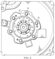
- Figure 4 shows a view of lockout device 20 from outside of gearbox 10.
- Screws 48 are used to couple housing 40 to cover 45 and can be removed when a lockout operation is desired.
- Bolts 42 couple housing to gearbox 10.
- Hex screws 36 couple inner collar 35 to outer collar 30.
- Ring 21 along shaft 25 prevents the leftward movement (in this view) of inner collar 35 along the exterior of shaft 25. Additionally, ring 21 can prevent shaft 25 from being pressed too far into gearbox 10.
- the user may push rightward (in this view) shaft 25 to engage teeth 58. The user can then rotate hex screws 36 (e.g., in a clockwise direction) - this will pull inner collar 35 and outer collar 30 toward each other.
- inner collar 35 will move right with regard to outer collar 30 and vice versa. This motion will force inner collar 35 against the surface of shaft 25 and lock the rotation of shaft 25, and by extension gearbox 10 and drive train 59 because shaft 25 is engaged with teeth 58 via teeth 27.
- the inner collar 35 and outer collar 30 engage each other along line 33, forcing each other in the movements described and thereby causing the locking functionality.
- Hex screws 36 pass through unthreaded holes in inner collar 35 and engage threaded holes in outer collar 30. The rotation of hex screws 36 pulls outer collar 30 and inner collar 35 together and forces inner collar 35 downward against the shaft 25.
- Holes 37 in inner collar 35 can be threaded. Screws or bolts placed here can be screwed in and can engage a flat face of outer collar 30. Rotating the screws/bolts sufficiently can push against the outer collar and move inner collar 35 leftward (from the view of Figure 3 ) and create additional freedom for the rotation of shaft 25.
- the screws or bolts used in holes 37 can be hex screws 36. Hex screws 36 can be removed from the threaded holes in outer collar 30 and threaded into holes 37. Removing hex screws 36 from outer collar 30 and threading them into holes 37 can be part of ending a lockout operation and preparing the gearbox for use.
- O-ring 18 provides sealing protection to keep any fluids or other material from entering gearbox 10 through the lockout device 20.
- Rims 43 of housing 40 can be shaped to abut the right edge (in this view) of outer collar 30 and to restrain rightward movement of outer collar 30 and inner collar 35 along shaft 25.
- Cover 45, or a portion thereof, can be clear or transparent and allow a user to visually inspect a status of lockout device 20.
- an indicator such as a toggle or flipped switch due to placement of the lockout device 20 components, can provide a user an indication of the status of lockout device 20 and/or gearbox 10.
- cover 45 has a ridge 70 that engages slot 72 on shaft 25. While the aircraft is in use and apart from times during lockout operations, ridge 70 and slot 72 hold shaft 25 in place with respect to cover 45 and prevent the engagement of teeth 27 with teeth 58.
- Housing 40 can comprise a slot or ridge for an o-ring 82 for engaging a portion of gearbox 10 to hold housing 40 stationary with respect to gearbox 10. The o-ring can provide an interference fit, sealing, and/or friction, between the housing and the gearbox. A portion of the interior of housing 40 can be hollow so as to save weight.
- Socket head 28 can be hex-shaped for use with a socket wrench when torquing shaft 25 and gearbox 10.
- Shaft 25 can also comprise threaded hole or receiving slot 29 at the bottom of socket head 28.
- Threaded hole 29 can be used with a threaded device to pull out shaft 25 if it gets pressed in too far.
- Socket head 28 can comprise other shapes besides a hexagonal shape. In some embodiments socket head 28 could comprise spline teeth that engage a tool for pulling out shaft 25. Socket head 28 could be square-shaped in other embodiments. Other shapes are possible as well if they allow for torquing the system.
- hex-shaped receiving components or screws, bolts, screw-driver compatible components, Phillips head compatible components, etc. While the Figures show certain embodiments, other shaped components can be used. For example, a hex-shaped socket head 28 is shown. But other embodiments could comprise a pentagonal-shaped head, Phillips screwdriver head, proprietary-shaped head, spline teeth that can be engaged, and other styles. The current disclosure is not limited to a specific set up regarding the use of hex or other shaped or compatible components.
- Step 510 is unscrewing a cover from its coupling to a housing, the housing comprising a hole therethrough and configured to be fixedly coupled to the gearbox.
- Step 520 is uncoupling the cover from a shaft, the shaft configured to pass through the hole and comprising a first plurality of teeth at one end and a socket head on a distal end, the shaft configured to be translatable along its axis, wherein coupling the shaft to the cover prevents the shaft from engaging the drive train.
- Step 530 is manipulating the shaft so as to engage a second plurality of teeth on the drive train with the first plurality of teeth so as to transmit rotation from the shaft to the drive train.
- Step 540 is applying a torque to the drive train by rotating the socket head.
- Step 550 is rotating a plurality of threaded bolts coupled to a plurality of threadless holes in an inner collar and a plurality of threaded holes in an outer collar, the inner collar configured to sit around the shaft and at least partially between the shaft and the housing, the outer collar configured to sit around the shaft and at least partially between the inner collar and the housing, wherein rotating the plurality of threaded bolts can adjust the relative position of the inner collar and the outer collar, wherein as the inner collar and the outer collar are pulled closer together the inner collar is pushed against the shaft and restricts a displacement of the shaft within the hole.
- Figures 6 to 12 can help illustrate additional views of a lockout device embodiment and the performance of a lockout procedure and ending the lockout for use of the aircraft.
- Figure 6 displays lockout device 600, comprising a housing 630 and cover 640, coupled to gearbox 650.
- Bolts 641 couple cover 640 to housing 630.
- Bolts 631 couple housing 630 to gearbox 650.
- threaded bolts 665 can be loosened, which will loosen the grip of inner collar 660 and outer collar 670 on shaft 620.
- shaft 620 can now be pushed axially into gearbox 650 so as to engage gear 655.
- Shaft 620 can comprise teeth 629 that engage gear 655.
- Gear 655 can comprise a portion of a drive train 657. Ring 623 on shaft 620 prevents the shaft 620 from being pressed too far into gearbox 650.
- threaded bolts 665 can be removed from outer collar 670 and be threaded into threaded holes 667. Using the threaded bolts 665 in threaded holes 667 will cause the tip of the threaded bolts 665 to press against a flat surface of outer collar 670 and thereby press inner collar 660 and outer collar 670 apart from each other and reduce grip on the shaft 620. Shaft 620 can now be pulled away from gear 655, allowing the gearbox 650 and drive train 657 to be operable for flight or other vehicle usage.
- Threaded bolts 665 can be retrieved from threaded holes 667 and reinserted into the inner collar 660 and outer collar 670 and tightened to "lock" the shaft in the unengaged position.
- Collar 640 ( Figure 12 ) can then be reattached to housing 630.
- Coupling 649 between collar 640 and shaft 620 can help hold shaft 620 in its locked and unengaged position so that it does not touch or engage gear 655 or drive train 657 during operation.
Landscapes
- Engineering & Computer Science (AREA)
- General Engineering & Computer Science (AREA)
- Mechanical Engineering (AREA)
- General Details Of Gearings (AREA)
Description
- The present invention relates to a lockout device and a method of performing a lockout operation.
- It is often necessary for the drive train of an aircraft to be mechanically locked (unable to rotate) for certain maintenance procedures and during transportation to prevent damage. On many rotorcraft transmissions, locking out of the device requires the installation of separate support equipment that typically bolts on a gearbox case. In some situations, the gearbox needs to be opened up and exposed to atmosphere to access a locking location. Some methods include the removal of a sealed cover over the interconnecting drive train section of the gearbox, and the installation of a tool that consists of a screw drive to lock the drive train. But there are problems with the prior solutions. The removal of the sealed cover significantly increases the risk of corrosion due to the environment exposure and possible water intrusion. The process requires a tool that is expensive to procure and is large/heavy.
-
US 5042749 discloses a mechanism for limiting rotation of a rotatably mounted first shaft. The mechanism includes a housing in which the first shaft is rotatably supported; a torque input coupled to the first shaft; and a torque output coupled to the first shaft; a second shaft rotatably supported by the housing and movable between a first axial position in which the second shaft does not engage the first shaft and a second axial position in which the second shaft engages the first shaft; at least one member attached to the second shaft which projects radially from the second shaft. The housing has an inner cavity with at least one surface which engages the at least one member which projects radially at first and second angular positions of the shafts to provide for a limited degree of angular rotation of the shafts when the second shaft is in the second axial position. -
US 2021/123518 discloses a gearbox assembly. The assembly includes a housing, an output shaft, a wheel gear, an input shaft, a torsion bar, an electric motor, a worm gear and a key lock. The wheel gear is be fixed to the output shaft for engagement with a wheel gear. The torsion bar connects the input shaft to the output shaft. The worm gear is rotationally fixed to the rotor and engages the wheel gear to transfer torque from the motor to the output shaft. The key lock includes an adapter, an annular outer part, a web, and a locking collar. The key lock is fixed to the housing and is movable between an extended position in which a part of the key lock engages the locking collar and a retracted position in which the part is held clear of the locking collar. -
WO 2013/020541 discloses a parking lock for a transmission. A transmission shaft, a transmission housing, a locking ring, a control element and a locking catch are disclosed. In this case, the locking catch is arranged moveably at a movement angle, wherein the movement of the locking catch causes an axial movement of the locking ring, and wherein, in an activated state of the locking ring, there is a form-fitting connection between the transmission shaft, transmission housing and locking ring. - One embodiment under the present invention comprises a lockout device for a gearbox.
- The device comprises a housing comprising a hole therethrough and configured to be fixedly coupled to the gearbox; a cover detachably coupled to the housing; and a shaft detachably coupled to the cover and configured to pass through the hole, the shaft comprising a plurality of teeth at one end and a receiving slot on a distal end, the plurality of teeth configured to engage a portion of a drive train within the gearbox and transmit rotation from the shaft to the drive train. It further comprises an inner collar configured to sit around the shaft and at least partially between the shaft and the housing, the inner collar comprising a plurality of threadless holes; and an outer collar configured to sit around the shaft and at least partially between the inner collar and the housing, the outer collar comprising a plurality of threaded holes configured to receive a plurality of bolts passing through the plurality of threadless holes, wherein rotation of the plurality of bolts can adjust the relative position of the inner collar and the outer collar, wherein as the inner collar and the outer collar are pulled closer together the inner collar is pushed against the shaft and restricts a displacement of the shaft within the hole.
- The present invention further relates to a method of performing a lockout operation to torque and lock a drive train within a gearbox. The method comprises unscrewing a cover from its coupling to a housing, the housing comprising a hole therethrough and configured to be fixedly coupled to the gearbox; and uncoupling the cover from a shaft, the shaft configured to pass through the hole and comprising a first plurality of teeth at one end and a socket head on a distal end, the shaft configured to be translatable along its axis, wherein coupling the shaft to the cover prevents the shaft from engaging the drive train. Further steps include manipulating the shaft so as to engage a second plurality of teeth on the drive train with the first plurality of teeth so as to transmit rotation from the shaft to the drive train, and applying a torque to the drive train by rotating the socket head. A further step is rotating a plurality of threaded bolts coupled to a plurality of threadless holes in an inner collar and a plurality of threaded holes in an outer collar, the inner collar configured to sit around the shaft and at least partially between the shaft and the housing, the outer collar configured to sit around the shaft and at least partially between the inner collar and the housing, wherein rotating the plurality of threaded bolts can adjust the relative position of the inner collar and the outer collar, wherein as the inner collar and the outer collar are pulled closer together the inner collar is pushed against the shaft and restricts a displacement of the shaft within the hole.
- This summary is provided to introduce a selection of concepts in a simplified form that are further described below in the detailed description. This summary is not intended to identify key features or essential features of the claimed subject matter, nor is it intended to be used as an indication of the scope of the claimed subject matter.
- For a more complete understanding of the present invention, reference is now made to the following descriptions taken in conjunction with the accompanying drawings, in which:
-
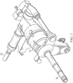
Fig. 1 shows a drive system for a tilt rotor aircraft; -
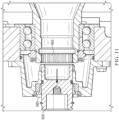
Fig. 2 shows a cut away view of a lockout device and gearbox embodiment under the present invention; -
Fig. 3 shows a cut away view of a lockout device and gearbox embodiment under the present invention; -
Fig. 4 shows an external view of a lockout device and gearbox embodiment under the present invention; and -
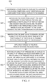
Fig. 5 shows a flow-chart of a method embodiment under the present invention; -
Fig. 6 shows a lockout device and gearbox embodiment under the present invention; -
Fig. 7 shows a lockout device and gearbox embodiment under the present invention; -
Figs. 8A-8B show a lockout device and gearbox embodiment under the present invention; -
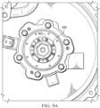
Figs. 9A-9B show a lockout device and gearbox embodiment under the present invention; -
Fig. 10 shows a lockout device and gearbox embodiment under the present invention; -
Fig. 11 shows a lockout device and gearbox embodiment under the present invention; and -
Fig. 12 shows a lockout device and gearbox embodiment under the present invention. - The present invention includes embodiments for an integrated gearbox lockout device that improves upon the prior art and solves the problems associated with prior approaches. Certain embodiments can utilize keyless locking technology to keep a gearbox from rotating when the lockout device is engaged. Furthermore, embodiments of the lockout device can remain installed on the gearbox and perform its functions while maintaining a seal between the environment and the internals of the gearbox.
- Benefits of embodiments under the present disclosure include, but are not limited to:
- A locking device that is integral to the gearbox, is externally accessible, and maintains a sealed gearbox environment throughout all modes of operation;
- A keyless design that allows the locking system to slip torsionally above a specified torque threshold without the creation of foreign object damage (FOD) or damaging components (prevents damage to other components if inadvertently left engaged);
- A sliding shaft that can be engaged or disengaged through external input; by allowing disengagement, no direct lubrication is required, and components do not wear during aircraft operation;
- A fail-safe feature that manually prevents the sliding shaft from engaging while the aircraft is in operation;
- A compact, self-contained design that can be retrofitted onto fielded gearboxes and replaced in the field without impacting other gearbox internals; and
- Specific packaging that prevents FOD from getting into the gearbox even in the event of component failure.
- One embodiment of a gearbox and drive shaft for a tilt rotor aircraft is shown in
Figure 1 . Gearbox 10 contains multiple gears that can provide power to drivetrain 20.Second drive train 30 can couplegearbox 10 to a central drive system of an aircraft. At certain times, such as during maintenance procedures, or shipping to another location, it may be desirable to lockgearbox 10 and/or drivetrain 20 such thatdrive train 20 is not capable of rotating by itself or of being moved by the gears withingearbox 10. - One embodiment of a lockout device under the present disclosure is shown in
Figure 2. Figure 2 shows a cut-away view of alockout device 20 coupled to agearbox 10, similar to thegearbox 10 ofFigure 1 .Lockout device 20 comprisesshaft 25,outer collar 30,inner collar 35,housing 40, and cover 45.Screws 48 couple cover 45 tohousing 40. While the aircraft is in use (or is otherwise not in a lockout operation) cover 45 will preferably be kept in place to protecthousing 40 andshaft 25 from wear and tear. When a user wishes to perform a lockout operation, cover 45 can be removed by removingscrews 48. When not in a lockout operation,shaft 25 withteeth 27 will sit to the left (in the view ofFigure 2 ) ofteeth 58 ofdrive train 59. When a user performs a lockout operation, cover 45 is removed and thenshaft 25 can be pushed to engageteeth 58. Socket head or receivingslot 28 inshaft 25 can receive a socket wrench operated by a user. The user can use the socket wrench to push inshaft 25 to engageteeth 58 withteeth 27, and then to rotate the shaft 25 (and by extension the gearbox 10) so as to torque upgearbox 10 and then restrain further movement during the lockout operation. - Further description of the movement of
shaft 25 and thelockout device 20 can be provided with respect toFigures 2 ,3 and4 . Reference numbers are kept consistent betweenFigures 2 to 4 so as to assist in illustrating the movement of the described components.Figure 2 shows a view oflockout device 20 unengaged fromteeth 58 ofgearbox 10.Figure 3 shows a view oflockout device 20 engaged inteeth 58.Figure 4 shows a view oflockout device 20 from outside ofgearbox 10. - Screws 48 (shown in ghost form in
Figures 3 and4 because they would be removed with the cover 45) are used to couplehousing 40 to cover 45 and can be removed when a lockout operation is desired.Bolts 42 couple housing togearbox 10. Hex screws 36 coupleinner collar 35 toouter collar 30.Ring 21 alongshaft 25 prevents the leftward movement (in this view) ofinner collar 35 along the exterior ofshaft 25. Additionally,ring 21 can preventshaft 25 from being pressed too far intogearbox 10. Once a user has removedcover 45, the user may push rightward (in this view)shaft 25 to engageteeth 58. The user can then rotate hex screws 36 (e.g., in a clockwise direction) - this will pullinner collar 35 andouter collar 30 toward each other. In the view shown,inner collar 35 will move right with regard toouter collar 30 and vice versa. This motion will forceinner collar 35 against the surface ofshaft 25 and lock the rotation ofshaft 25, and byextension gearbox 10 and drivetrain 59 becauseshaft 25 is engaged withteeth 58 viateeth 27. Theinner collar 35 andouter collar 30 engage each other alongline 33, forcing each other in the movements described and thereby causing the locking functionality. Hex screws 36 pass through unthreaded holes ininner collar 35 and engage threaded holes inouter collar 30. The rotation of hex screws 36 pullsouter collar 30 andinner collar 35 together and forcesinner collar 35 downward against theshaft 25. -
Holes 37 ininner collar 35, visible inFigure 4 , can be threaded. Screws or bolts placed here can be screwed in and can engage a flat face ofouter collar 30. Rotating the screws/bolts sufficiently can push against the outer collar and moveinner collar 35 leftward (from the view ofFigure 3 ) and create additional freedom for the rotation ofshaft 25. The screws or bolts used inholes 37 can be hex screws 36. Hex screws 36 can be removed from the threaded holes inouter collar 30 and threaded intoholes 37. Removing hex screws 36 fromouter collar 30 and threading them intoholes 37 can be part of ending a lockout operation and preparing the gearbox for use. - O-
ring 18 provides sealing protection to keep any fluids or other material from enteringgearbox 10 through thelockout device 20.Rims 43 ofhousing 40 can be shaped to abut the right edge (in this view) ofouter collar 30 and to restrain rightward movement ofouter collar 30 andinner collar 35 alongshaft 25.Cover 45, or a portion thereof, can be clear or transparent and allow a user to visually inspect a status oflockout device 20. Alternatively, an indicator, such as a toggle or flipped switch due to placement of thelockout device 20 components, can provide a user an indication of the status oflockout device 20 and/orgearbox 10. - As seen in
Figure 2 , cover 45 has aridge 70 that engagesslot 72 onshaft 25. While the aircraft is in use and apart from times during lockout operations,ridge 70 andslot 72hold shaft 25 in place with respect to cover 45 and prevent the engagement ofteeth 27 withteeth 58.Housing 40 can comprise a slot or ridge for an o-ring 82 for engaging a portion ofgearbox 10 to holdhousing 40 stationary with respect togearbox 10. The o-ring can provide an interference fit, sealing, and/or friction, between the housing and the gearbox. A portion of the interior ofhousing 40 can be hollow so as to save weight. -
Socket head 28 can be hex-shaped for use with a socket wrench when torquingshaft 25 andgearbox 10.Shaft 25 can also comprise threaded hole or receivingslot 29 at the bottom ofsocket head 28. Threadedhole 29 can be used with a threaded device to pull outshaft 25 if it gets pressed in too far.Socket head 28 can comprise other shapes besides a hexagonal shape. In someembodiments socket head 28 could comprise spline teeth that engage a tool for pulling outshaft 25.Socket head 28 could be square-shaped in other embodiments. Other shapes are possible as well if they allow for torquing the system. - Reference has been made to hex-shaped receiving components, or screws, bolts, screw-driver compatible components, Phillips head compatible components, etc. While the Figures show certain embodiments, other shaped components can be used. For example, a hex-shaped
socket head 28 is shown. But other embodiments could comprise a pentagonal-shaped head, Phillips screwdriver head, proprietary-shaped head, spline teeth that can be engaged, and other styles. The current disclosure is not limited to a specific set up regarding the use of hex or other shaped or compatible components. -
Figure 5 shows amethod embodiment 500 under the present disclosure. Step 510 is unscrewing a cover from its coupling to a housing, the housing comprising a hole therethrough and configured to be fixedly coupled to the gearbox. Step 520 is uncoupling the cover from a shaft, the shaft configured to pass through the hole and comprising a first plurality of teeth at one end and a socket head on a distal end, the shaft configured to be translatable along its axis, wherein coupling the shaft to the cover prevents the shaft from engaging the drive train. Step 530 is manipulating the shaft so as to engage a second plurality of teeth on the drive train with the first plurality of teeth so as to transmit rotation from the shaft to the drive train. Step 540 is applying a torque to the drive train by rotating the socket head. Step 550 is rotating a plurality of threaded bolts coupled to a plurality of threadless holes in an inner collar and a plurality of threaded holes in an outer collar, the inner collar configured to sit around the shaft and at least partially between the shaft and the housing, the outer collar configured to sit around the shaft and at least partially between the inner collar and the housing, wherein rotating the plurality of threaded bolts can adjust the relative position of the inner collar and the outer collar, wherein as the inner collar and the outer collar are pulled closer together the inner collar is pushed against the shaft and restricts a displacement of the shaft within the hole. -
Figures 6 to 12 can help illustrate additional views of a lockout device embodiment and the performance of a lockout procedure and ending the lockout for use of the aircraft. -
Figure 6 displays lockout device 600, comprising ahousing 630 and cover 640, coupled togearbox 650.Bolts 641couple cover 640 tohousing 630.Bolts 631couple housing 630 togearbox 650. -
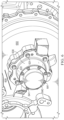
Bolts 641 can be removed to begin a lockout procedure. As seen inFigure 7 , cover 640 has been removed.Holes 642 onhousing 630 are now empty after the removal ofbolts 641.Shaft 620 can now be seen.Socket head 622,ring 623, and threadedhole 624 are also seen.Inner collar 660 is seen with threadedbolts 665 that coupleinner collar 660 to outer collar 670 (not shown inFigure 7 ). Threadedholes 667 are shown, empty right now but available to receive threadedbolts 665 to assist in pushinginner collar 660 away fromouter collar 670. - Referring to
Figures 8A-8B , threadedbolts 665 can be loosened, which will loosen the grip ofinner collar 660 andouter collar 670 onshaft 620. Referring toFigure 8B ,shaft 620 can now be pushed axially intogearbox 650 so as to engagegear 655.Shaft 620 can compriseteeth 629 that engagegear 655.Gear 655 can comprise a portion of adrive train 657.Ring 623 onshaft 620 prevents theshaft 620 from being pressed too far intogearbox 650. - Moving to
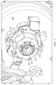
Figures 9A-9B , aftershaft 620 has been moved to engagegear 655, threadedbolts 665 can be tightened, drawingouter collar 670 andinner collar 660 closer together and pushinginner collar 660 more tightly aroundshaft 620. After sufficient tightening (Figure 9B ) theshaft 620 will be "locked" ingear 655. Cover 640 can be reattached and the vehicle and/or gearbox can be shipped, undergo maintenance or storage, or as otherwise desired. - When the user desires to end the lockout procedure, the
cover 640 can be removed again. As seen inFigure 10 , threadedbolts 665 can be removed fromouter collar 670 and be threaded into threadedholes 667. Using the threadedbolts 665 in threadedholes 667 will cause the tip of the threadedbolts 665 to press against a flat surface ofouter collar 670 and thereby pressinner collar 660 andouter collar 670 apart from each other and reduce grip on theshaft 620.Shaft 620 can now be pulled away fromgear 655, allowing thegearbox 650 and drivetrain 657 to be operable for flight or other vehicle usage. Threadedbolts 665 can be retrieved from threadedholes 667 and reinserted into theinner collar 660 andouter collar 670 and tightened to "lock" the shaft in the unengaged position. Collar 640 (Figure 12 ) can then be reattached tohousing 630. Coupling 649 betweencollar 640 andshaft 620 can help holdshaft 620 in its locked and unengaged position so that it does not touch or engagegear 655 or drivetrain 657 during operation.
Claims (14)
- A lockout device (20) for a gearbox (10), comprising:a housing (40) comprising a hole therethrough and configured to be fixedly coupled to the gearbox (10);a shaft (25) detachably coupled to the housing and configured to pass through the hole, the shaft comprising a plurality of teeth (27) at one end and a receiving slot (28) on a distal end, the plurality of teeth configured to engage a portion of a drive train (59) within the gearbox and transmit rotation from the shaft to the drive train;an inner collar (35) configured to sit around the shaft and at least partially between the shaft and the housing, characterized by the inner collar comprising a plurality of threadless holes; andan outer collar (30) configured to sit around the shaft and at least partially between the inner collar and the housing, the outer collar comprising a plurality of threaded holes configured to receive a plurality of bolts (36) passing through the plurality of threadless holes, wherein rotation of the plurality of bolts can adjust the relative position of the inner collar and the outer collar, wherein as the inner collar and the outer collar are pulled closer together the inner collar is pushed against the shaft and restricts a displacement of the shaft within the hole.
- The lockout device of claim 1, wherein the shaft comprises a second receiving slot (29) at a bottom edge of the receiving slot.
- The lockout device of claim 2, wherein the second receiving slot comprises a plurality of threads.
- The lockout device of claim 1, further comprising a cover (45) detachably coupled to the housing, and wherein the shaft is detachably coupled to the cover.
- The lockout device of claim 1, wherein the inner collar comprises a second plurality of threaded holes (37) configured to allow a second plurality of bolts (36) to pass therethrough and engage a surface of the outer collar.
- The lockout device of claim 1, wherein the shaft comprises a ring (21) configured to engage an edge of the inner collar and prevent further displacement of the shaft within the hole.
- The lockout device of claim 1, wherein the housing comprises a rim (43) proximate the hole configured to restrict displacement of the outer collar.
- The lockout device of claim 1, wherein the shaft comprises an o-ring (18) configured to seal a gap between the shaft and the housing.
- A method (500) of performing a lockout operation to torque and lock a drive train within a gearbox (10, 650), the method comprising:detaching (510) a cover (45, 640) from its coupling to a housing (40, 630), the housing comprising a hole therethrough and configured to be fixedly coupled to the gearbox;uncoupling (520) the cover from a shaft (25, 620), the shaft configured to pass through the hole and comprising a first plurality of teeth (27, 629) at one end and a socket head (28, 622) on a distal end, the shaft configured to be translatable along its axis, wherein coupling the shaft to the cover prevents the shaft from engaging the drive train;manipulating (530) the shaft so as to engage a second plurality of teeth (58, 655) on the drive train with the first plurality of teeth so as to transmit rotation from the shaft to the drive train;applying (540) a torque to the drive train by rotating the socket head; androtating (550) a plurality of threaded bolts (36, 665) coupled to a plurality of threadless holes in an inner collar and a plurality of threaded holes in an outer collar, the inner collar configured to sit around the shaft and at least partially between the shaft and the housing, the outer collar configured to sit around the shaft and at least partially between the inner collar and the housing, wherein rotating the plurality of threaded bolts can adjust the relative position of the inner collar and the outer collar, wherein as the inner collar and the outer collar are pulled closer together the inner collar is pushed against the shaft and restricts a displacement of the shaft within the hole.
- The method of claim 9 further comprising, prior to the manipulating, rotating the plurality of threaded bolts (36, 665) through a second plurality of threaded holes (37, 667) in the inner collar, the second plurality of threaded holes (37, 667) configured to allow the plurality of threaded bolts to pass therethrough and engage a flat surface of the outer collar to push the inner collar and outer collar away from each other, wherein as the inner collar and the outer collar are pushed away from each other the shaft is given greater freedom of movement along its axis.
- The method of claim 9, wherein manipulating the shaft comprises moving the shaft toward the drive train until the inner collar stops the movement of a ring (21, 623) comprising the shaft.
- The method of claim 9, further comprising re-attaching the cover to the housing.
- The method of claim 9, further comprising checking a status of the shaft by at least one of: looking through a transparent portion of the cover; checking an indicator switch or bottom that shows when the cover is engaged to the shaft; checking an electric sensor; checking an electric switch.
- The method of claim 9, further comprising threading a threaded member into a threaded slot at the bottom of the socket head and pulling the shaft out of the drive train with the threaded member.
Applications Claiming Priority (1)
| Application Number | Priority Date | Filing Date | Title |
|---|---|---|---|
| US17/885,034 US11859706B1 (en) | 2022-08-10 | 2022-08-10 | Integrated gearbox lockout device |
Publications (2)
| Publication Number | Publication Date |
|---|---|
| EP4328467A1 EP4328467A1 (en) | 2024-02-28 |
| EP4328467B1 true EP4328467B1 (en) | 2025-02-26 |
Family
ID=87047856
Family Applications (1)
| Application Number | Title | Priority Date | Filing Date |
|---|---|---|---|
| EP23181165.4A Active EP4328467B1 (en) | 2022-08-10 | 2023-06-23 | Integrated gearbox lockout device |
Country Status (2)
| Country | Link |
|---|---|
| US (3) | US11859706B1 (en) |
| EP (1) | EP4328467B1 (en) |
Families Citing this family (1)
| Publication number | Priority date | Publication date | Assignee | Title |
|---|---|---|---|---|
| US11859706B1 (en) * | 2022-08-10 | 2024-01-02 | Textron Innovations Inc. | Integrated gearbox lockout device |
Family Cites Families (12)
| Publication number | Priority date | Publication date | Assignee | Title |
|---|---|---|---|---|
| US2691541A (en) * | 1949-12-05 | 1954-10-12 | Melba L Benedek | Shaft bushing for mountable machine elements |
| CH582314A5 (en) * | 1974-09-14 | 1976-11-30 | Ringfeder Gmbh | |
| JPS5848788B2 (en) * | 1979-10-12 | 1983-10-31 | 日本発条株式会社 | Lock mechanism in propulsion device |
| US4304502A (en) * | 1979-11-15 | 1981-12-08 | Andrew Stratienko | Torque and thrust transmitting bushings |
| US4922599A (en) * | 1989-01-09 | 1990-05-08 | Mark Durfee | Method of converting a four speed manual transmission to a five speed transmission |
| US5042749A (en) * | 1990-04-10 | 1991-08-27 | Sundstrand Corporation | Mechanism for limiting rotation of a rotatably mounted shaft |
| US5286232A (en) * | 1992-04-10 | 1994-02-15 | Borg-Warner Automotive Diversified Transmission Products Corporation | Slip yoke assembly for output of power transmission device |
| US6098753A (en) * | 1998-06-05 | 2000-08-08 | Pratt & Whitney Canada Corp. | System for delivering pressurized lubricant fluids to an interior of a rotating hollow shaft |
| DE102012015012B4 (en) * | 2011-08-06 | 2024-02-15 | Neumayer Tekfor Engineering Gmbh | Parking lock |
| US20150102033A1 (en) | 2013-10-11 | 2015-04-16 | Silgan Plastics Llc | Container with high density molecular weight polyethylene moisture barrier layer |
| GB2592091B (en) * | 2019-10-29 | 2024-02-14 | Zf Steering Systems Poland Sp Z O O | A gearbox assembly for a vehicle |
| US11859706B1 (en) * | 2022-08-10 | 2024-01-02 | Textron Innovations Inc. | Integrated gearbox lockout device |
-
2022
- 2022-08-10 US US17/885,034 patent/US11859706B1/en active Active
-
2023
- 2023-06-23 EP EP23181165.4A patent/EP4328467B1/en active Active
- 2023-12-21 US US18/392,942 patent/US12188548B2/en active Active
-
2024
- 2024-12-19 US US18/987,808 patent/US20250116325A1/en active Pending
Also Published As
| Publication number | Publication date |
|---|---|
| US20250116325A1 (en) | 2025-04-10 |
| US12188548B2 (en) | 2025-01-07 |
| EP4328467A1 (en) | 2024-02-28 |
| US20240125378A1 (en) | 2024-04-18 |
| US11859706B1 (en) | 2024-01-02 |
Similar Documents
| Publication | Publication Date | Title |
|---|---|---|
| US6679361B2 (en) | Emergency facilities for influencing defective constituents of power trains in motor vehicles | |
| US8590417B1 (en) | Trailer landing gear apparatus | |
| US6796385B1 (en) | Fastener driving machine and associated method | |
| EP4015803B1 (en) | Quick access engine rotator pad | |
| US20120318082A1 (en) | Apparatus for converting a rotational movement into an axial movement | |
| JPS6227520Y2 (en) | ||
| US20060116232A1 (en) | Manually adjustable clutch assembly with visual indicator | |
| EP4443023B1 (en) | Axle assembly and method of controlling positioning of a shift mechanism | |
| US20250116325A1 (en) | Integrated Gearbox Lockout Device | |
| US8516916B2 (en) | Linear actuator | |
| US5609090A (en) | Actuator with protective end cap | |
| WO2025231504A1 (en) | Adaptor device, retainer means, tool and system | |
| US20190376563A1 (en) | Power screw mechanism with rotation clutch | |
| US4585025A (en) | Mounting for a valve actuator | |
| JP2011520692A (en) | Brake unit | |
| CN108233606B (en) | Manual override of the drive | |
| EP4150225A1 (en) | Joint arrangement, electric motor and industrial actuator | |
| WO2019141564A1 (en) | Disk clutch assembly | |
| US4655106A (en) | Tube or pipe profiling apparatus | |
| EP4446621A2 (en) | Axle assembly having a shift mechanism | |
| US20250357833A1 (en) | Motor extraction tool and related methods | |
| JPS626984Y2 (en) | ||
| JP3649772B2 (en) | Power take-off device | |
| GB2358895A (en) | Automated power train of a vehicle with emergency control in the event of malfunction | |
| HK1111132A (en) | Tire insert attachment apparatus |
Legal Events
| Date | Code | Title | Description |
|---|---|---|---|
| PUAI | Public reference made under article 153(3) epc to a published international application that has entered the european phase |
Free format text: ORIGINAL CODE: 0009012 |
|
| STAA | Information on the status of an ep patent application or granted ep patent |
Free format text: STATUS: REQUEST FOR EXAMINATION WAS MADE |
|
| STAA | Information on the status of an ep patent application or granted ep patent |
Free format text: STATUS: EXAMINATION IS IN PROGRESS |
|
| 17P | Request for examination filed |
Effective date: 20230623 |
|
| AK | Designated contracting states |
Kind code of ref document: A1 Designated state(s): AL AT BE BG CH CY CZ DE DK EE ES FI FR GB GR HR HU IE IS IT LI LT LU LV MC ME MK MT NL NO PL PT RO RS SE SI SK SM TR |
|
| 17Q | First examination report despatched |
Effective date: 20240212 |
|
| GRAP | Despatch of communication of intention to grant a patent |
Free format text: ORIGINAL CODE: EPIDOSNIGR1 |
|
| STAA | Information on the status of an ep patent application or granted ep patent |
Free format text: STATUS: GRANT OF PATENT IS INTENDED |
|
| RIC1 | Information provided on ipc code assigned before grant |
Ipc: F16H 57/023 20120101ALN20240911BHEP Ipc: F16H 57/00 20120101ALN20240911BHEP Ipc: F16H 63/34 20060101ALI20240911BHEP Ipc: F16H 61/22 20060101AFI20240911BHEP |
|
| RIC1 | Information provided on ipc code assigned before grant |
Ipc: F16H 57/023 20120101ALN20240916BHEP Ipc: F16H 57/00 20120101ALN20240916BHEP Ipc: F16H 63/34 20060101ALI20240916BHEP Ipc: F16H 61/22 20060101AFI20240916BHEP |
|
| INTG | Intention to grant announced |
Effective date: 20241008 |
|
| GRAS | Grant fee paid |
Free format text: ORIGINAL CODE: EPIDOSNIGR3 |
|
| GRAA | (expected) grant |
Free format text: ORIGINAL CODE: 0009210 |
|
| STAA | Information on the status of an ep patent application or granted ep patent |
Free format text: STATUS: THE PATENT HAS BEEN GRANTED |
|
| AK | Designated contracting states |
Kind code of ref document: B1 Designated state(s): AL AT BE BG CH CY CZ DE DK EE ES FI FR GB GR HR HU IE IS IT LI LT LU LV MC ME MK MT NL NO PL PT RO RS SE SI SK SM TR |
|
| REG | Reference to a national code |
Ref country code: GB Ref legal event code: FG4D |
|
| REG | Reference to a national code |
Ref country code: CH Ref legal event code: EP |
|
| P01 | Opt-out of the competence of the unified patent court (upc) registered |
Free format text: CASE NUMBER: APP_5613/2025 Effective date: 20250203 |
|
| REG | Reference to a national code |
Ref country code: DE Ref legal event code: R096 Ref document number: 602023002177 Country of ref document: DE |
|
| REG | Reference to a national code |
Ref country code: IE Ref legal event code: FG4D |
|
| REG | Reference to a national code |
Ref country code: NL Ref legal event code: MP Effective date: 20250226 |
|
| PG25 | Lapsed in a contracting state [announced via postgrant information from national office to epo] |
Ref country code: RS Free format text: LAPSE BECAUSE OF FAILURE TO SUBMIT A TRANSLATION OF THE DESCRIPTION OR TO PAY THE FEE WITHIN THE PRESCRIBED TIME-LIMIT Effective date: 20250526 |
|
| PG25 | Lapsed in a contracting state [announced via postgrant information from national office to epo] |
Ref country code: FI Free format text: LAPSE BECAUSE OF FAILURE TO SUBMIT A TRANSLATION OF THE DESCRIPTION OR TO PAY THE FEE WITHIN THE PRESCRIBED TIME-LIMIT Effective date: 20250226 |
|
| PG25 | Lapsed in a contracting state [announced via postgrant information from national office to epo] |
Ref country code: PL Free format text: LAPSE BECAUSE OF FAILURE TO SUBMIT A TRANSLATION OF THE DESCRIPTION OR TO PAY THE FEE WITHIN THE PRESCRIBED TIME-LIMIT Effective date: 20250226 |
|
| PGFP | Annual fee paid to national office [announced via postgrant information from national office to epo] |
Ref country code: DE Payment date: 20250627 Year of fee payment: 3 |
|
| PG25 | Lapsed in a contracting state [announced via postgrant information from national office to epo] |
Ref country code: ES Free format text: LAPSE BECAUSE OF FAILURE TO SUBMIT A TRANSLATION OF THE DESCRIPTION OR TO PAY THE FEE WITHIN THE PRESCRIBED TIME-LIMIT Effective date: 20250226 |
|
| REG | Reference to a national code |
Ref country code: LT Ref legal event code: MG9D |
|
| PG25 | Lapsed in a contracting state [announced via postgrant information from national office to epo] |
Ref country code: NO Free format text: LAPSE BECAUSE OF FAILURE TO SUBMIT A TRANSLATION OF THE DESCRIPTION OR TO PAY THE FEE WITHIN THE PRESCRIBED TIME-LIMIT Effective date: 20250526 Ref country code: IS Free format text: LAPSE BECAUSE OF FAILURE TO SUBMIT A TRANSLATION OF THE DESCRIPTION OR TO PAY THE FEE WITHIN THE PRESCRIBED TIME-LIMIT Effective date: 20250626 |
|
| PG25 | Lapsed in a contracting state [announced via postgrant information from national office to epo] |
Ref country code: NL Free format text: LAPSE BECAUSE OF FAILURE TO SUBMIT A TRANSLATION OF THE DESCRIPTION OR TO PAY THE FEE WITHIN THE PRESCRIBED TIME-LIMIT Effective date: 20250226 |
|
| PG25 | Lapsed in a contracting state [announced via postgrant information from national office to epo] |
Ref country code: HR Free format text: LAPSE BECAUSE OF FAILURE TO SUBMIT A TRANSLATION OF THE DESCRIPTION OR TO PAY THE FEE WITHIN THE PRESCRIBED TIME-LIMIT Effective date: 20250226 |
|
| PG25 | Lapsed in a contracting state [announced via postgrant information from national office to epo] |
Ref country code: LV Free format text: LAPSE BECAUSE OF FAILURE TO SUBMIT A TRANSLATION OF THE DESCRIPTION OR TO PAY THE FEE WITHIN THE PRESCRIBED TIME-LIMIT Effective date: 20250226 Ref country code: PT Free format text: LAPSE BECAUSE OF FAILURE TO SUBMIT A TRANSLATION OF THE DESCRIPTION OR TO PAY THE FEE WITHIN THE PRESCRIBED TIME-LIMIT Effective date: 20250626 |
|
| PGFP | Annual fee paid to national office [announced via postgrant information from national office to epo] |
Ref country code: FR Payment date: 20250625 Year of fee payment: 3 |
|
| PG25 | Lapsed in a contracting state [announced via postgrant information from national office to epo] |
Ref country code: GR Free format text: LAPSE BECAUSE OF FAILURE TO SUBMIT A TRANSLATION OF THE DESCRIPTION OR TO PAY THE FEE WITHIN THE PRESCRIBED TIME-LIMIT Effective date: 20250527 Ref country code: BG Free format text: LAPSE BECAUSE OF FAILURE TO SUBMIT A TRANSLATION OF THE DESCRIPTION OR TO PAY THE FEE WITHIN THE PRESCRIBED TIME-LIMIT Effective date: 20250226 |
|
| REG | Reference to a national code |
Ref country code: AT Ref legal event code: MK05 Ref document number: 1770903 Country of ref document: AT Kind code of ref document: T Effective date: 20250226 |
|
| PG25 | Lapsed in a contracting state [announced via postgrant information from national office to epo] |
Ref country code: SE Free format text: LAPSE BECAUSE OF FAILURE TO SUBMIT A TRANSLATION OF THE DESCRIPTION OR TO PAY THE FEE WITHIN THE PRESCRIBED TIME-LIMIT Effective date: 20250226 |
|
| PG25 | Lapsed in a contracting state [announced via postgrant information from national office to epo] |
Ref country code: SM Free format text: LAPSE BECAUSE OF FAILURE TO SUBMIT A TRANSLATION OF THE DESCRIPTION OR TO PAY THE FEE WITHIN THE PRESCRIBED TIME-LIMIT Effective date: 20250226 |
|
| PG25 | Lapsed in a contracting state [announced via postgrant information from national office to epo] |
Ref country code: DK Free format text: LAPSE BECAUSE OF FAILURE TO SUBMIT A TRANSLATION OF THE DESCRIPTION OR TO PAY THE FEE WITHIN THE PRESCRIBED TIME-LIMIT Effective date: 20250226 |
|
| PG25 | Lapsed in a contracting state [announced via postgrant information from national office to epo] |
Ref country code: IT Free format text: LAPSE BECAUSE OF FAILURE TO SUBMIT A TRANSLATION OF THE DESCRIPTION OR TO PAY THE FEE WITHIN THE PRESCRIBED TIME-LIMIT Effective date: 20250226 |
|
| PG25 | Lapsed in a contracting state [announced via postgrant information from national office to epo] |
Ref country code: AT Free format text: LAPSE BECAUSE OF FAILURE TO SUBMIT A TRANSLATION OF THE DESCRIPTION OR TO PAY THE FEE WITHIN THE PRESCRIBED TIME-LIMIT Effective date: 20250226 |
|
| PG25 | Lapsed in a contracting state [announced via postgrant information from national office to epo] |
Ref country code: EE Free format text: LAPSE BECAUSE OF FAILURE TO SUBMIT A TRANSLATION OF THE DESCRIPTION OR TO PAY THE FEE WITHIN THE PRESCRIBED TIME-LIMIT Effective date: 20250226 Ref country code: CZ Free format text: LAPSE BECAUSE OF FAILURE TO SUBMIT A TRANSLATION OF THE DESCRIPTION OR TO PAY THE FEE WITHIN THE PRESCRIBED TIME-LIMIT Effective date: 20250226 |
|
| PG25 | Lapsed in a contracting state [announced via postgrant information from national office to epo] |
Ref country code: RO Free format text: LAPSE BECAUSE OF FAILURE TO SUBMIT A TRANSLATION OF THE DESCRIPTION OR TO PAY THE FEE WITHIN THE PRESCRIBED TIME-LIMIT Effective date: 20250226 |
|
| PG25 | Lapsed in a contracting state [announced via postgrant information from national office to epo] |
Ref country code: SK Free format text: LAPSE BECAUSE OF FAILURE TO SUBMIT A TRANSLATION OF THE DESCRIPTION OR TO PAY THE FEE WITHIN THE PRESCRIBED TIME-LIMIT Effective date: 20250226 |
|
| REG | Reference to a national code |
Ref country code: DE Ref legal event code: R097 Ref document number: 602023002177 Country of ref document: DE |
|
| PLBE | No opposition filed within time limit |
Free format text: ORIGINAL CODE: 0009261 |
|
| STAA | Information on the status of an ep patent application or granted ep patent |
Free format text: STATUS: NO OPPOSITION FILED WITHIN TIME LIMIT |
|
| PG25 | Lapsed in a contracting state [announced via postgrant information from national office to epo] |
Ref country code: MC Free format text: LAPSE BECAUSE OF FAILURE TO SUBMIT A TRANSLATION OF THE DESCRIPTION OR TO PAY THE FEE WITHIN THE PRESCRIBED TIME-LIMIT Effective date: 20250226 |
|
| 26N | No opposition filed |
Effective date: 20251127 |
|
| PG25 | Lapsed in a contracting state [announced via postgrant information from national office to epo] |
Ref country code: LU Free format text: LAPSE BECAUSE OF NON-PAYMENT OF DUE FEES Effective date: 20250623 |
|
| REG | Reference to a national code |
Ref country code: BE Ref legal event code: MM Effective date: 20250630 |
|
| PG25 | Lapsed in a contracting state [announced via postgrant information from national office to epo] |
Ref country code: IE Free format text: LAPSE BECAUSE OF NON-PAYMENT OF DUE FEES Effective date: 20250623 |
|
| PG25 | Lapsed in a contracting state [announced via postgrant information from national office to epo] |
Ref country code: BE Free format text: LAPSE BECAUSE OF NON-PAYMENT OF DUE FEES Effective date: 20250630 |