EP4328371A1 - Washing machine, and control apparatus, control method and control system therefor - Google Patents
Washing machine, and control apparatus, control method and control system therefor Download PDFInfo
- Publication number
- EP4328371A1 EP4328371A1 EP21938964.0A EP21938964A EP4328371A1 EP 4328371 A1 EP4328371 A1 EP 4328371A1 EP 21938964 A EP21938964 A EP 21938964A EP 4328371 A1 EP4328371 A1 EP 4328371A1
- Authority
- EP
- European Patent Office
- Prior art keywords
- water level
- water
- detection device
- level detection
- inlet valve
- Prior art date
- Legal status (The legal status is an assumption and is not a legal conclusion. Google has not performed a legal analysis and makes no representation as to the accuracy of the status listed.)
- Pending
Links
Images


Classifications
-
- D—TEXTILES; PAPER
- D06—TREATMENT OF TEXTILES OR THE LIKE; LAUNDERING; FLEXIBLE MATERIALS NOT OTHERWISE PROVIDED FOR
- D06F—LAUNDERING, DRYING, IRONING, PRESSING OR FOLDING TEXTILE ARTICLES
- D06F34/00—Details of control systems for washing machines, washer-dryers or laundry dryers
- D06F34/14—Arrangements for detecting or measuring specific parameters
-
- D—TEXTILES; PAPER
- D06—TREATMENT OF TEXTILES OR THE LIKE; LAUNDERING; FLEXIBLE MATERIALS NOT OTHERWISE PROVIDED FOR
- D06F—LAUNDERING, DRYING, IRONING, PRESSING OR FOLDING TEXTILE ARTICLES
- D06F33/00—Control of operations performed in washing machines or washer-dryers
- D06F33/30—Control of washing machines characterised by the purpose or target of the control
- D06F33/32—Control of operational steps, e.g. optimisation or improvement of operational steps depending on the condition of the laundry
- D06F33/34—Control of operational steps, e.g. optimisation or improvement of operational steps depending on the condition of the laundry of water filling
-
- D—TEXTILES; PAPER
- D06—TREATMENT OF TEXTILES OR THE LIKE; LAUNDERING; FLEXIBLE MATERIALS NOT OTHERWISE PROVIDED FOR
- D06F—LAUNDERING, DRYING, IRONING, PRESSING OR FOLDING TEXTILE ARTICLES
- D06F33/00—Control of operations performed in washing machines or washer-dryers
- D06F33/30—Control of washing machines characterised by the purpose or target of the control
- D06F33/32—Control of operational steps, e.g. optimisation or improvement of operational steps depending on the condition of the laundry
-
- D—TEXTILES; PAPER
- D06—TREATMENT OF TEXTILES OR THE LIKE; LAUNDERING; FLEXIBLE MATERIALS NOT OTHERWISE PROVIDED FOR
- D06F—LAUNDERING, DRYING, IRONING, PRESSING OR FOLDING TEXTILE ARTICLES
- D06F33/00—Control of operations performed in washing machines or washer-dryers
- D06F33/30—Control of washing machines characterised by the purpose or target of the control
- D06F33/47—Responding to irregular working conditions, e.g. malfunctioning of pumps
-
- D—TEXTILES; PAPER
- D06—TREATMENT OF TEXTILES OR THE LIKE; LAUNDERING; FLEXIBLE MATERIALS NOT OTHERWISE PROVIDED FOR
- D06F—LAUNDERING, DRYING, IRONING, PRESSING OR FOLDING TEXTILE ARTICLES
- D06F37/00—Details specific to washing machines covered by groups D06F21/00 - D06F25/00
- D06F37/42—Safety arrangements, e.g. for stopping rotation of the receptacle upon opening of the casing door
-
- D—TEXTILES; PAPER
- D06—TREATMENT OF TEXTILES OR THE LIKE; LAUNDERING; FLEXIBLE MATERIALS NOT OTHERWISE PROVIDED FOR
- D06F—LAUNDERING, DRYING, IRONING, PRESSING OR FOLDING TEXTILE ARTICLES
- D06F39/00—Details of washing machines not specific to a single type of machines covered by groups D06F9/00 - D06F27/00
- D06F39/04—Heating arrangements
-
- D—TEXTILES; PAPER
- D06—TREATMENT OF TEXTILES OR THE LIKE; LAUNDERING; FLEXIBLE MATERIALS NOT OTHERWISE PROVIDED FOR
- D06F—LAUNDERING, DRYING, IRONING, PRESSING OR FOLDING TEXTILE ARTICLES
- D06F39/00—Details of washing machines not specific to a single type of machines covered by groups D06F9/00 - D06F27/00
- D06F39/08—Liquid supply or discharge arrangements
- D06F39/087—Water level measuring or regulating devices
-
- D—TEXTILES; PAPER
- D06—TREATMENT OF TEXTILES OR THE LIKE; LAUNDERING; FLEXIBLE MATERIALS NOT OTHERWISE PROVIDED FOR
- D06F—LAUNDERING, DRYING, IRONING, PRESSING OR FOLDING TEXTILE ARTICLES
- D06F39/00—Details of washing machines not specific to a single type of machines covered by groups D06F9/00 - D06F27/00
- D06F39/40—Steam generating arrangements
-
- D—TEXTILES; PAPER
- D06—TREATMENT OF TEXTILES OR THE LIKE; LAUNDERING; FLEXIBLE MATERIALS NOT OTHERWISE PROVIDED FOR
- D06F—LAUNDERING, DRYING, IRONING, PRESSING OR FOLDING TEXTILE ARTICLES
- D06F2103/00—Parameters monitored or detected for the control of domestic laundry washing machines, washer-dryers or laundry dryers
- D06F2103/18—Washing liquid level
-
- D—TEXTILES; PAPER
- D06—TREATMENT OF TEXTILES OR THE LIKE; LAUNDERING; FLEXIBLE MATERIALS NOT OTHERWISE PROVIDED FOR
- D06F—LAUNDERING, DRYING, IRONING, PRESSING OR FOLDING TEXTILE ARTICLES
- D06F2105/00—Systems or parameters controlled or affected by the control systems of washing machines, washer-dryers or laundry dryers
- D06F2105/02—Water supply
-
- D—TEXTILES; PAPER
- D06—TREATMENT OF TEXTILES OR THE LIKE; LAUNDERING; FLEXIBLE MATERIALS NOT OTHERWISE PROVIDED FOR
- D06F—LAUNDERING, DRYING, IRONING, PRESSING OR FOLDING TEXTILE ARTICLES
- D06F2105/00—Systems or parameters controlled or affected by the control systems of washing machines, washer-dryers or laundry dryers
- D06F2105/28—Electric heating
-
- D—TEXTILES; PAPER
- D06—TREATMENT OF TEXTILES OR THE LIKE; LAUNDERING; FLEXIBLE MATERIALS NOT OTHERWISE PROVIDED FOR
- D06F—LAUNDERING, DRYING, IRONING, PRESSING OR FOLDING TEXTILE ARTICLES
- D06F34/00—Details of control systems for washing machines, washer-dryers or laundry dryers
- D06F34/14—Arrangements for detecting or measuring specific parameters
- D06F34/22—Condition of the washing liquid, e.g. turbidity
Definitions
- Embodiments of the present disclosure relate to, but are not limited to, the field of electrical equipment, and in particular, but not limited to, a washing machine, and a control apparatus, control method and control system therefor.
- a control apparatus for a washing machine may include an outer tub.
- the control apparatus includes a plurality of water level detection devices.
- the plurality of water level detection devices includes a first water level detection device and a second water level detection device.
- the first water level detection device is configured to detect a predetermined water level in the outer tub
- the second water level detection device is configured to detect a water level in the outer tub.
- a washing machine may include: a processor, an inner tub, an outer tub, and the above control apparatus.
- the inner tub is located within the outer tub, and the processor is electrically connected to the control apparatus.
- a control method for a washing machine is provided.
- the method may be applied to the above washing machine.
- the method may include: detecting the predetermined water level in the outer tub of the washing machine by the first water level detection device of the washing machine; and detecting a water level in the outer tub by the second water level detection device of the washing machine.
- a control system for a washing machine includes an outer tub.
- the control system includes a plurality of water level detection devices, a processor, a heating device, and a water inlet valve.
- the plurality of water level detection devices includes a first water level detection device and a second water level detection device.
- the first water level detection device is configured to detect a predetermined water level in the outer tub
- the second water level detection device is configured to detect a water level in the outer tub.
- the processor is configured to control the heating device and the water inlet valve based on detection signals of the plurality of water level detection devices.
- Reference number Term Reference number Term 1 Control apparatus 2 Washing machine 11 First water level detection device 12 Second water level detection device 22 Inner tub 21 Outer tub H1 First high water level H2 First low water level h1 Second high water level h2 Second low water level 23 Heating device 25 Processor 24 Water inlet valve 3 Control system
- Embodiments of the present disclosure provide a control apparatus 1 for a washing machine.
- a washing machine 2 may include an outer tub 21, and the control apparatus 1 may include a plurality of water level detection devices.
- the plurality of water level detection devices may include a first water level detection device 11 and a second water level detection device 12.
- the first water level detection device 11 is configured to detect a predetermined water level in the outer tub 21, and the second water level detection device 12 is configured to detect a water level in the outer tub 21.
- a plurality of water level detection devices with different detection principles may be provided at the outer tub.
- two water level detection devices are provided, i.e., the first water level detection device 11 and the second water level detection device 12 are provided.
- the detecting the predetermined water level refers to determining whether an actual water level reaches a fixed water level
- the detecting a water level refers to detecting the actual water level in real time
- a plurality of predetermined water levels is provided.
- two predetermined water levels are provided in an embodiment of the present disclosure, and are defined as a first high water level H1 and a first low water level H2.
- the second water level detection device has two thresholds. That is, a second high water level h1 and a second low water level h2 are provided, and H1 ⁇ h1 and H2 ⁇ h2 may be satisfied.
- a detection process may include: supplying water, and performing heating when the actual water level is greater than h2; stopping the water supply when the actual water level reaches h1; and stopping the heating and supplying water when the water level is lower than h2.
- the water supply may be stopped when the actual water level reaches H1, and the heating may be stopped when the actual water level reaches H2. Therefore, the first water level detection device 11 has a guarantee function, and ensures that clothes cannot get wet or dry burning cannot occur, in response to the misjudgment or the detection failure of the second water level detection device 12.
- the washing machine may further include an inner tub 22 located within the outer tub 21, and the control apparatus 1 may further include a heating device 23.
- the heating device 23 may be disposed between a bottom of the inner tub 22 and a bottom of the outer tub 21.
- the heating device 23 may be configured to heat water supplied to the outer tub 21 to generate steam.
- the heating device 23 may be located between the inner tub 22 and the outer tub 21, for example, may be disposed between the bottom of the inner tub 22 and the bottom of the outer tub 21.
- the inner tub 22 may have at least one first through hole, and the at least one first through hole may be configured to provide steam generated between the inner tub 22 and the outer tub 21 with a passage access to the inner tub 22.
- the outer tub 21 may be connected to a water inlet interface to supply water into the outer tub 21 through the water inlet interface.
- the first water level detection device 11 includes a first water level detection portion, and the first water level detection portion of the first water level detection device 11 is disposed between the bottom of the inner tub 22 and the bottom of the outer tub 21.
- the second water level detection device 12 includes a second water level detection portion, the second water level detection portion of the second water level detection device 12 is disposed at an outlet of a drain pipe of the washing machine, and the drain pipe may be in communication with the outer tub 21.
- the first water level detection portion is located at a position higher than a position where the second water level detection portion is located.
- the first water level detection portion may be located at a position higher than a position where the heating device is located.
- the first low water level H2 may be higher than a predetermined position of the heating device 23.
- the first water level detection portion may be located at a predetermined height of the water level in the outer tub 21, and therefore only the water level at the predetermined height (such as, the first high water level H1 and the first low water level H2) may be detected.
- the second water level detection portion may be disposed at the outlet of the drain pipe, and may detect the water level in the outer tub 21.
- the first water level detection portion configured to limit a maximum height of the water level may be disposed below the bottom of the inner tub 22 to detect the first high water level H1.
- a dry burning prevention water level may be provided above the heating device 23 and between the bottom of the inner tub 22 and the bottom of the outer tub 21, in order to prevent dry burning of the heating device 23 caused by starting the heating device 23 when a small amount of water is supplied.
- the first low water level H2 is provided, and may be detected by the first water level detection portion.
- the first high water level H1 is a predetermined safe water level, which can be used to prevent the detection fault of the second water level detection device or the failure of the second water level detection device from occurring and thus avoiding continuous supplying of the water from a water inlet valve, thereby preventing the water in the outer tub 21 from entering the inner tub 22 to wet the clothes and from influencing a steam effect.
- the safe water level is provided.
- any one or more of the following measures may be selected: the water inlet valve is closed and a safety alarm is sent to remind a user (for example, sound, light and a combination thereof may be used, but are not limited thereto); or the washing machine may be directly turned off to avoid further damage to the washing machine due to the detection failure caused by a fault of the washing machine.
- the first low water level H2 when the first low water level H2 is set to be a safe water level, the first low water level H2 may be used to prevent potential safety hazard caused by taking no corresponding protection measure when a water level in the outer tub 21 has been lowered below the safe water level through continuous heating of the heating device 23 due to the detection fault of the second water level detection device or the failure of the second water level detection device.
- the safe water level is configured to, in response to the first water level detection device 11 detecting that the water level has been lower than or equal to the safe water level, select one or more of the following measures: the heating device 23 is turned off, water is supplied into the outer tub 21, and a safety alarm is sent to remind a user, for example, any sound, light and a combination thereof may be used, but are not limited thereto; or the washing machine may be directly turned off to avoid damage to the washing machine.
- the first water level detection device 11 may be a water level switch
- the second water level detection device 12 may be a Micro-Electro-Mechanical System, MEMS, water level sensor.
- the water level switch is disposed at the first high water level H1 and the first low water level H2, and thus the water level switch can be controllable to be opened and closed in time when the water level of the outer tub 21 reaches the predetermined water level. Therefore, a valve body (such as, the water inlet valve) and the heating device in the washing machine are correspondingly controlled.
- the water level in the outer tub 21 may be intelligently detected by the MEMS water level sensor.
- the combination of the MEMS water level sensor and the water level switch is configured to synthetically determine the water level in the outer tub 21, which ensures safe and effective operation of the washing machine in a steam washing process.
- a specific value of each of the first high water level H1, the first low water level H2, the second high water level h1 and the second low water level h2 is also not limited, and it is possible to employ different configurations based on different washing machine models, different inner tub sizes, different outer tub sizes, different internal spaces, and the like.
- a height calculation benchmark (i.e., a water level of 0) of each of the first high water level H1, the first low water level H2, the second high water level h1 and the second low water level h2 may be a horizontal plane arbitrarily configured between the bottom of the outer tub 21 and the bottom of the inner tub 22.
- the height calculation benchmark of each of the first high water level H1, the first low water level H2, the second high water level h1 and the second low water level h2 may also be the bottom of the inner tub 22, that is, the height of the water level is calculated from the bottom of the inner tub 22.
- a height of the predetermined water level i.e., a vertical distance between the predetermined water level and the bottom of the outer tub 21, may be set to be d/2-3d/ 4, where d may be a vertical distance between the bottom of the inner tub 22 and the bottom of the outer tub 21.
- the heating device 23 there is a distance between the heating device 23 and the bottom of the inner tub 22.
- the water inlet valve at the water inlet pipeline is controlled to be opened to supply water to a certain height into the outer tub 21, and the water in the outer tub 21 is heated by the heating device 23 of the washing machine to generate the steam at the bottom of the tub. Therefore, the steam washing function is realized.
- the first high water level H1, the first low water level H2, the second high water level h1 and the second low water level h2 may all be higher than the position where the heating device 23 is located in order to avoid dry burning.
- the heating device 23 may be disposed at a position between d/3-d/2, that is, a vertical distance between the heating device 23 and the bottom of the outer tub 21 is d/3-d/2.
- the heating device may be a heating pipe, a heating plate, and the like.
- a specific implementation form, a setting position, a setting quantity, model selection, heating power and the like of the heating device are not limited herein, and may be customized based on specific requirements.
- the water level switch may be disposed between the heating device 23 and the bottom of the inner tub 22, and the MEMS water level sensor is connected to the bottom of the outer tub 21.
- the water level switch and the MEMS water level sensor are combined to determine the water level, and the water inlet valve and/or the heating device is controlled to be turned on or turned off based on the determined water level to implement the steam washing function smoothly.
- the height of the water level in the outer tub 21 is detected by the MEMS water level sensor during normal water supply.
- the heating device 23 may be controlled to start heating to generate steam, in response to the MEMS water level sensor detecting that the water level in the outer tub 21 reaches the second low water level h2.
- the height of the water level in the outer tub 21 is continuously detected by the MEMS water level sensor.
- the water inlet valve may be controlled to be closed to stop the water supply, in response to the MEMS water level sensor detecting that the water level in the outer tub 21 reaches the second high water level h2. Therefore, the water is prevented from entering the inner tub to wet the clothes due to too high water level.
- the water level in the outer tub 21 is detected by the water level switch at the same time during the normal water supply process.
- the water inlet valve is controlled to be closed to stop the water supply in order to avoid water flow entering the inner tub 22 through a plurality of first through holes formed at the inner tub 22 to wet the clothes due to continuous supply of the water.
- the heating device may be continuously controlled to keep in the operating state, and therefore the heating device continuously heats the water to continuously generate the steam.
- the water inlet valve in response to the water level switch detecting that the water level in the outer tub 21 is higher than or equal to the first high water level H1, no matter whether the height of the water level detected by the MEMS water level sensor reaches the predetermined threshold, the water inlet valve is controlled to be closed to stop the water supply, and the heating device is controlled to keep in the operating state to continuously heat the water.
- the heating device in response to the water level switch detecting that the water level at the bottom of the outer tub 21 is lower than or equal to the first low water level H2, no matter whether the height of the water level detected by the MEMS water level sensor reaches the predetermined threshold, the heating device is directly controlled to immediately stop the heating, for example, the water level switch cuts off a heating main circuit of the heating device, to avoid dry burning.
- the water inlet valve can be controlled to be in an open state to continue to supply the water into the outer tub 21, to allow the water level to be higher than the safe water level (i.e., the first low water level H2).
- Embodiments of the present disclosure further provide a washing machine 2.
- the washing machine 2 may include a processor 25, an inner tub 22, an outer tub 21, and the above control apparatus 1.
- control apparatus 1 may include a heating device 23, a water inlet valve 24, and a plurality of water level detection devices.
- the plurality of water level detection devices may include a first water level detection device 11 and a second water level detection device 12.
- the first water level detection device 11 may be configured to detect a predetermined water level in the outer tub 21.
- the second water level detection device 12 may be configured to detect a water level in the outer tub 21.
- the heating device 23 may be disposed between the bottom of the inner tub 22 and the bottom of the outer tub 21, and may be configured to heat water in the outer tub 21.
- the water inlet valve 24 may be configured to be opened to supply water into the outer tub 21, in response to the second water level detection device 12 detecting that the water level is lower than the second low water level h2.
- the water inlet valve 24 may be configured to supply the water into the outer tub 21 by opening the water inlet valve 24, and to stop the supply of the water into the outer tub 21 by closing the water inlet valve 24.
- the processor 25 may be configured to control the heating device 23 and the water inlet valve 24 based on detection signals of the above at least one water level detection device.
- the predetermined water level may include a first high water level H1 and a first low water level H2.
- the second water level detection device may correspond to at least two water level thresholds including a second high water level h1 and a second low water level h2. That is, the second water level detection device may detect a water level between the second high water level h1 and the second low water level h2, where H1 > H2, h1 > h2, H1 ⁇ h1, and H2 ⁇ h2.
- the heating device 23 may be configured to perform heating to generate steam, in response to the second water level detection device 12 detecting that the current water level reaches the second low water level h2.
- the water inlet valve 24 may be configured to be closed to stop the water supply, in response to the second water level detection device 12 detecting that the current water level reaches the second high water level h1.
- the heating device 23 may further be configured to stop the heating, in response to the first water level detection device 11 detecting that the current water level is lower than the first low water level H2.
- the water inlet valve 24 may be further configured to be closed to stop the water supply, in response to the first water level detection device 11 detecting that the current water level reaches the first high water level H1.
- the processor 25 controls the heating device 23 and the water inlet valve 24 based on the detection signals of the at least one water level detection device.
- This control of the processor 25 may include: controlling, subsequent to a predetermined steam washing program being started, the water inlet valve 24 to be opened to supply water into the outer tub 21; controlling the heating device 23 to perform the heating to generate the steam, in response to the second water level detection device 12 detecting that the current water level reaches the second low water level h2; controlling the water inlet valve 24 to be closed to stop the water supply, in response to the second water level detection device 12 detecting that the current water level reaches the second high water level h1; and controlling the water inlet valve to be opened again to supply water again, in response to the second water level detection device 12 detecting that the current water level is lower than the second low water level h2.
- controlling the heating device 23 and the water inlet valve 24 by the processor 25 based on the detection signals of the at least one water level detection device may include: controlling the heating device 23 to stop the heating, in response to the first water level detection device 11 detecting that the current water level is lower than the first low water level H2; and controlling the water inlet valve 24 to be closed to stop the water supply, in response to the first water level detection device 11 detecting that the current water level reaches the first high water level H1.
- any embodiment in the above control apparatus is applicable to the embodiments of the washing machine, and details thereof are not repeated herein.
- Embodiments of the present disclosure further provide a control system 3 for a washing machine.
- the control system 3 may include a plurality of water level detection devices, a processor 25, a heating device 23, and a water inlet valve 24.
- the plurality of water level detection devices, the heating device 23 and the water inlet valve 24 are electrically connected to the processor 25.
- the plurality of water level detection devices may include a first water level detection device 11 and a second water level detection device 12.
- the first water level detection device 11 is configured to detect a predetermined water level in an outer tub 21 of the washing machine
- the second water level detection device 12 is configured to detect a water level in the outer tub 21.
- the processor 25 is configured to control the heating device 23 and the water inlet valve 24 based on detection signals of the plurality of water level detection devices.
- the predetermined water level includes a first high water level H1 and a first low water level H2.
- the processor 25 is further configured to: control the heating device 23 to perform heating to generate steam, in response to the second water level detection device 12 detecting that a current water level reaches the second low water level h2; control the water inlet valve 24 to be opened to supply water, in response to the second water level detection device 12 detecting that the current water level is lower than the second low water level h2; control the water inlet valve 24 to be closed to stop the water supply, in response to the second water level detection device 12 detecting that the current water level reaches the second high water level h1; control, regardless of a detection result of the second water level detection device 12, the heating device to stop the heating, in response to the first water level detection device 11 detecting that the current water level is lower than the first low water level H2; and control, regardless of the detection result of the second water level detection device 12, the water inlet valve 24 to be closed to stop the water supply, in response to the first water level detection device detecting that the current water level reaches the first high water level H1, where H1 > H2, h1 >
- Embodiments of the present disclosure further provide a control method of a washing machine.
- the control method may be applied in any one of the washing machines as described above.
- the control method may be implemented by the above-mentioned processor 25. As illustrated in FIG. 4 , the control method may include operations at blocks S101 and S102.
- the predetermined water level in the outer tub of the washing machine is detected by the first water level detection device 11 of the washing machine.
- a water level in the outer tub 21 is detected by the second water level detection device 12 of the washing machine.
- a plurality of and/or a plurality types of water level detection devices may be used to detect a water level in the outer tub.
- the washing machine may further include a heating device and a water inlet valve.
- the heating device may be configured to perform heating of water supplied into the outer tub to generate steam in the steam washing process.
- the water inlet valve may be disposed at a water inlet pipe of the washing machine that may be connected to the outer tub 21. The supply of the water into the outer tub and stopping the water supply can be controlled by opening and closing the water inlet valve.
- control method may further include operations at blocks S201 to S204.
- the water inlet valve may be controlled to be opened to supply water into the outer tub 21 subsequent to a predetermined steam washing program being started.
- the heating device 23 may be controlled to perform the heating to generate the steam when the current water level reaches the second low water level h2.
- the water inlet valve may be controlled to be closed to stop the water supply when the current water level reaches the second high water level h1.
- the water inlet valve is controlled to be opened to supply water again when the current water level is lower than the second low water level h2 due to the water being consumed.
- the heating device 23 may be disposed between the outer tub 21 and the bottom of the inner tub 22. During supplying of water into the outer tub 21, when the water level in the outer tub 21 reaches the second low water level h2, it is indicated that the water level in the outer tub 21 has exceeded a predetermined height of the heating device. In this case, the heating device 23 may be turned on to perform heating to generate steam, as there is definitely no dry heating when the heating device 23 is turned on at this moment.
- the water inlet valve 24 is controlled to be continuously opened to continuously supply water into the outer tub 21.
- the preset second water level detection device 12 detects that the current water level reaches the second high water level h1
- the water inlet valve may be controlled to be closed to stop the supply of the water into the outer tub 21.
- the heating device is controlled to be heated continuously, and a heating power of the heating device may be adjusted based on requirements, to control an amount and/or a speed of the generated steam.
- a heating mode for the heating device 23 may be automatically defined based on requirements without being specified in detail.
- the heating device 23 may continuously perform heating with a predetermined heating power, may perform the heating with a continuously changing heating power, may also perform intermittent heating (i.e., stopping a certain duration after heating for a certain duration), and may also perform the heating by combining the above-mentioned heating modes.
- control method may further include: controlling, during the heating of the heating device 23, the water inlet valve to be opened again to supply water again when the current water level in the outer tub 21 is lower than the second low water level h2.
- the water in the outer tub 21 is gradually converted into steam as a heating duration increases.
- the water in the outer tub 21 inevitably decreases.
- the water inlet valve may be controlled to be opened again to supply water into the outer tub 21 again, in response to detecting that the water level is lower than or equal to the second low water level h2.
- the water inlet valve is controlled to be closed again to stop the supply of the water into the outer tub 21.
- water is supplied again, in response to detecting that the water level is lower than or equal to the second low water level h2.
- the water supply may be stopped again, in response to detecting that the water level has reached the second high water level h1.
- This process may be continuously performed until the predetermined steam washing process ends. For example, a predetermined steam washing duration reaches.
- the water supply is immediately stopped, when the detection of the second water level detection device 12 fails and thus the first water level detection device 11 detects that the water level reaches the first high water level H1.
- the heating is stopped immediately, in response to the first water level detection device 11 detecting that the water level is lower than or equal to the first low water level H2.
- an additional detection may be performed by the first water level detection device 11.
- the heating device is controlled to stop operation in time, in response to the first water level detection device 11 detecting that the water level is equal to or lower than the first low water level H2.
- the additional detection of the first water level detection device 11 may also be perform.
- the water inlet valve is controlled to be closed in time to stop the water supply, in response to the first water level detection device 11 detecting that the water level is equal to or higher than the first high water level H1.
- the inner tub may be controlled to rotate synchronously during the water supply prior to the steam generation.
- the rotation speed of the inner tub may be a first rotation speed r1.
- the first rotation speed r1 during the water supply may be a larger value, and therefore even if the water falls onto an outer wall of the inner tub during the water supply, the water is thrown off due to the rotation of the inner tub at the high speed. Thus, water flow cannot smoothly enter the inner tub through the first through hole to prevent the internal clothes from being wetted.
- the inner tub is simultaneously controlled to rotate at a high speed during the water supply, the water flow can be effectively prevented from entering the inner tub. Therefore, the clothes are prevented from getting wet by the water. Further, many problems possibly arise from the above-mentioned analysis are avoided. Therefore, the embodiments of the present disclosure solve a large problem in the steam washing by increasing the rotation speed of the inner tub during the water supply.
- the heating device starts heating, and the water level reaches the predetermined water level.
- the inner tub may still be controlled to rotate in this case.
- the rotation speed of the inner tub may be a lower rotation speed in this case, for example, a second rotation speed r2.
- the second rotation speed r2 is slower than the first rotation speed r1.
- low-speed rotation is performed to enable the generated steam to pass through the first through hole into the inner tub, which avoids the steam from being blocked outside the inner tub due to too high rotation speed.
- the low-speed rotation of the inner tub enables the clothes in the inner tub to be gradually shaken out to allow for a larger contact area between the clothes and air in the inner tub. Therefore, the clothes can be in contact with the steam in a larger area. Thus, a wrinkle-removing effect is enhanced.
- the specific value of the second rotational speed r2 may be defined based on different types of washing machines, different capacities, different motor configurations, and different requirements, and the specific value of the second rotational speed r2 is not limited herein.
- the inner tub in the process of generating steam, when the inner tub rotates at a lower speed, the inner tub may rotate clockwise and anticlockwise alternately. During the alternate rotation of the inner tub, the inner tub may rotate one or more revolutions clockwise, and then rotates one or more revolutions countercl ockwi se.
- control method may further include: during the heating of the heating device, detecting whether the water level in the outer tub 21 has decreased to the second low water level h2 in real time, and continuously performing the heating to generate the steam, in response to detecting that the water level in the outer tub 21 has not decreased to the second low water level h2; and supplying water into the outer tub 21 again, and controlling the inner tub to rotate at a high speed again during the re-supply of the water, in response to detecting that the water level in the outer tub 21 decreases to the second low water level h2.
- the amount of water in the outer tub is relatively little.
- water can be supplied into the outer tub again in order to prevent dry burning.
- the rotation speed of the inner tub is still increased during the re-supply of the water to allow the inner tub to rotate at a high speed during the water supply, and the speed of the inner tub can be reduced again after the water supply is completed.
- first and second in the embodiments of the present disclosure are used for description, and are not intended to indicate or imply relative importance or significance.
- the feature defined with “first” and “second” may include at least one feature.
- a plurality of means at least two, for example, two or three, unless specified otherwise.
- connection is understood broadly, such as fixed, detachable mountings, connections and couplings or integrated, and can be mechanical or electrical mountings, connections and couplings, and also can be direct and via media indirect mountings, connections, and couplings, and further can be inner mountings, connections and couplings of two components or interaction relations between two components, which can be understood by those skilled in the art according to the detail embodiment of the present disclosure.
- the division between the functional modules/units mentioned in the above description does not necessarily correspond to a division of physical components.
- one physical component may have a plurality of functions, or one function or step may be cooperatively performed by several physical components.
- Some or all of the components may be implemented as software executed by a processor, such as a digital signal processor or a microprocessor, or as hardware, or as an integrated circuit, such as an application specific integrated circuit.
- Such software may be distributed on a computer readable medium, which may include a computer storage medium (or a non-transitory medium) and a communication medium (or a transitory medium).
- a computer storage medium or a non-transitory medium
- a communication medium or a transitory medium
- computer storage medium includes a volatile and nonvolatile and removable and non-removable medium implemented in any method or technology for storing information, such as, computer readable instructions, a data structure, a program module, or other data.
- the computer storage medium includes, but is not limited to, RAM, ROM, EEPROM, flash memory or other memory technology, CD-ROM, digital versatile disks (DVD) or other optical disk storage, magnetic cassettes, magnetic tape, magnetic disk storage or other magnetic storage devices, or any other medium that can be used to store desired information and that can be accessed by a computer.
- a communication medium typically embodies computer the readable instructions, the data structure, the program module, or the other data in a modulated data signal such as a carrier wave or other transmission mechanism, and may include any information delivery medium.
- the specification may have presented methods and/or processes as a particular sequence of steps in describing representative embodiments.
Landscapes
- Engineering & Computer Science (AREA)
- Textile Engineering (AREA)
- Control Of Washing Machine And Dryer (AREA)
- Detail Structures Of Washing Machines And Dryers (AREA)
Abstract
Description
- Embodiments of the present disclosure relate to, but are not limited to, the field of electrical equipment, and in particular, but not limited to, a washing machine, and a control apparatus, control method and control system therefor.
- In some washing machines, it is required to reliably determine a height of a water level at a bottom of a tub in order to achieve a steam washing function with steam at the bottom of the tub. If the determination is incorrect, on the one hand, an excessively low water level may lead to dry burning of a heating pipe, causing a safety accident; and on the other hand, an excessively high water level may wet clothes, affecting user experience.
- The following is the summary of subject matters detailed in the present disclosure. This summary is not intended to limit the scope of claims.
- A control apparatus for a washing machine is provided. The washing machine may include an outer tub. The control apparatus includes a plurality of water level detection devices. The plurality of water level detection devices includes a first water level detection device and a second water level detection device. The first water level detection device is configured to detect a predetermined water level in the outer tub, and the second water level detection device is configured to detect a water level in the outer tub.
- A washing machine is provided. The washing machine may include: a processor, an inner tub, an outer tub, and the above control apparatus. The inner tub is located within the outer tub, and the processor is electrically connected to the control apparatus.
- A control method for a washing machine is provided. The method may be applied to the above washing machine. The method may include: detecting the predetermined water level in the outer tub of the washing machine by the first water level detection device of the washing machine; and detecting a water level in the outer tub by the second water level detection device of the washing machine.
- A control system for a washing machine is provided. The washing machine includes an outer tub. The control system includes a plurality of water level detection devices, a processor, a heating device, and a water inlet valve. The plurality of water level detection devices includes a first water level detection device and a second water level detection device. The first water level detection device is configured to detect a predetermined water level in the outer tub, and the second water level detection device is configured to detect a water level in the outer tub. The processor is configured to control the heating device and the water inlet valve based on detection signals of the plurality of water level detection devices.
- Other aspects will be apparent after reading and understanding the drawings and detailed description.
- The accompanying drawings are used to provide further understanding of technical solutions herein and form part of the specification, and are used in conjunction with embodiments of the present disclosure to explain the technical solutions herein and do not constitute limitation to the technical solutions herein.
-
FIG. 1 is a composition block diagram of a water intake control apparatus for a washing machine according to an embodiment of the present disclosure. -
FIG. 2 is a schematic structural view of a washing machine according to an embodiment of the present disclosure. -
FIG. 2a is a schematic structural view of a part A inFIG. 2 . -
FIG. 3 is a composition block diagram of a washing machine according to an embodiment of the present disclosure. -
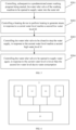
FIG. 4 is a first flowchart of a water intake control method of a washing machine according to an embodiment of the present disclosure. -
FIG. 5 is a second flowchart of a water intake control method of a washing machine according to an embodiment of the present disclosure. -
FIG. 6 is a composition block diagram of a water intake control apparatus for a washing machine according to an embodiment of the present disclosure. - Description of reference numbers:
Reference number Term Reference number Term 1 Control apparatus 2 Washing machine 11 First water level detection device 12 Second water level detection device 22 Inner tub 21 Outer tub H1 First high water level H2 First low water level h1 Second high water level h2 Second low water level 23 Heating device 25 Processor 24 Water inlet valve 3 Control system - Embodiments of the present disclosure will be described below in conjunction with the accompanying drawings. It should be noted that the embodiments and features in the embodiments in the present disclosure may be combined with each other in any combination without conflict.
- Embodiments of the present disclosure provide a
control apparatus 1 for a washing machine. As illustrated inFIG. 1, FIG. 2 andFIG. 2a , awashing machine 2 may include anouter tub 21, and thecontrol apparatus 1 may include a plurality of water level detection devices. The plurality of water level detection devices may include a first waterlevel detection device 11 and a second waterlevel detection device 12. The first waterlevel detection device 11 is configured to detect a predetermined water level in theouter tub 21, and the second waterlevel detection device 12 is configured to detect a water level in theouter tub 21. - When a steam washing function is performed in the washing machine, it is inevitable to heat supplied water to generate steam. If there is fault or even error in determining the water level, on the one hand, it may causes excessively low water level, which may result in dry burning of a heating pipe to bring safety accidents, and lead to damage to an inner assembly of the washing machine and affect a service life of the washing machine. On the other hand, the wrong determination may cause excessively high water level, and the water flow inevitably enters the inner tub of the washing machine and wet the clothes, and therefore the clothes are piled up due to an increased weight of the clothes after water absorption. Thus, a contact area between the clothes and the steam is small. In addition, since the clothes have absorbed too much water, little or no steam is absorbed. As a result, a steam washing effect is seriously affected, and user experience is also influenced. Therefore, it is required to reliably determine a height of a water level in the outer tub during this process.
- In exemplary embodiments of the present disclosure, in order to accurately detect a water level in the
outer tub 21, a plurality of water level detection devices with different detection principles may be provided at the outer tub. For example, two water level detection devices are provided, i.e., the first waterlevel detection device 11 and the second waterlevel detection device 12 are provided. - In exemplary embodiments of the present disclosure, the detecting the predetermined water level refers to determining whether an actual water level reaches a fixed water level, and the detecting a water level refers to detecting the actual water level in real time.
- In exemplary embodiments of the present disclosure, a plurality of predetermined water levels is provided. For example, two predetermined water levels are provided in an embodiment of the present disclosure, and are defined as a first high water level H1 and a first low water level H2.
- In exemplary embodiments of the present disclosure, the second water level detection device has two thresholds. That is, a second high water level h1 and a second low water level h2 are provided, and H1≥h1 and H2≤h2 may be satisfied.
- In exemplary embodiments of the present disclosure, only the second water level detection device is required to perform water level detection. A detection process may include: supplying water, and performing heating when the actual water level is greater than h2; stopping the water supply when the actual water level reaches h1; and stopping the heating and supplying water when the water level is lower than h2.
- In the exemplary embodiment of the present disclosure, since H1≥h1 and H2≤h2, the actual water level normally does not reach H1 and H2.
- In the exemplary embodiment of the present disclosure, in response to inaccurate detection or detection failure of the second water
level detection device 12, the water supply may be stopped when the actual water level reaches H1, and the heating may be stopped when the actual water level reaches H2. Therefore, the first waterlevel detection device 11 has a guarantee function, and ensures that clothes cannot get wet or dry burning cannot occur, in response to the misjudgment or the detection failure of the second waterlevel detection device 12. - In exemplary embodiments of the present disclosure, the washing machine may further include an
inner tub 22 located within theouter tub 21, and thecontrol apparatus 1 may further include aheating device 23. Theheating device 23 may be disposed between a bottom of theinner tub 22 and a bottom of theouter tub 21. - In exemplary embodiments of the present disclosure, the
heating device 23 may be configured to heat water supplied to theouter tub 21 to generate steam. Theheating device 23 may be located between theinner tub 22 and theouter tub 21, for example, may be disposed between the bottom of theinner tub 22 and the bottom of theouter tub 21. Theinner tub 22 may have at least one first through hole, and the at least one first through hole may be configured to provide steam generated between theinner tub 22 and theouter tub 21 with a passage access to theinner tub 22. Theouter tub 21 may be connected to a water inlet interface to supply water into theouter tub 21 through the water inlet interface. - In exemplary embodiments of the present disclosure, the first water
level detection device 11 includes a first water level detection portion, and the first water level detection portion of the first waterlevel detection device 11 is disposed between the bottom of theinner tub 22 and the bottom of theouter tub 21. - In exemplary embodiments of the present disclosure, the second water
level detection device 12 includes a second water level detection portion, the second water level detection portion of the second waterlevel detection device 12 is disposed at an outlet of a drain pipe of the washing machine, and the drain pipe may be in communication with theouter tub 21. - In exemplary embodiments of the present disclosure, the first water level detection portion is located at a position higher than a position where the second water level detection portion is located.
- The first water level detection portion may be located at a position higher than a position where the heating device is located.
- In exemplary embodiments of the present disclosure, the first low water level H2 may be higher than a predetermined position of the
heating device 23. - In exemplary embodiments of the present disclosure, the first water level detection portion may be located at a predetermined height of the water level in the
outer tub 21, and therefore only the water level at the predetermined height (such as, the first high water level H1 and the first low water level H2) may be detected. The second water level detection portion may be disposed at the outlet of the drain pipe, and may detect the water level in theouter tub 21. For example, in order to prevent the water level from being too high after water supplying, the first water level detection portion configured to limit a maximum height of the water level may be disposed below the bottom of theinner tub 22 to detect the first high water level H1. - In exemplary embodiments of the present disclosure, when the
heating device 23 is disposed between the bottom of theinner tub 22 and the bottom of theouter tub 21, a dry burning prevention water level may be provided above theheating device 23 and between the bottom of theinner tub 22 and the bottom of theouter tub 21, in order to prevent dry burning of theheating device 23 caused by starting theheating device 23 when a small amount of water is supplied. For example, the first low water level H2 is provided, and may be detected by the first water level detection portion. - In exemplary embodiments of the present disclosure, when the first high water level H1 is a predetermined safe water level, which can be used to prevent the detection fault of the second water level detection device or the failure of the second water level detection device from occurring and thus avoiding continuous supplying of the water from a water inlet valve, thereby preventing the water in the
outer tub 21 from entering theinner tub 22 to wet the clothes and from influencing a steam effect. - In exemplary embodiments of the present disclosure, the safe water level is provided. In this way, in response to the first water
level detection device 11 detecting that the water level has been higher than the safe water level, any one or more of the following measures may be selected: the water inlet valve is closed and a safety alarm is sent to remind a user (for example, sound, light and a combination thereof may be used, but are not limited thereto); or the washing machine may be directly turned off to avoid further damage to the washing machine due to the detection failure caused by a fault of the washing machine. - In exemplary embodiments of the present disclosure, when the first low water level H2 is set to be a safe water level, the first low water level H2 may be used to prevent potential safety hazard caused by taking no corresponding protection measure when a water level in the
outer tub 21 has been lowered below the safe water level through continuous heating of theheating device 23 due to the detection fault of the second water level detection device or the failure of the second water level detection device. - In exemplary embodiments of the present disclosure, the safe water level is configured to, in response to the first water
level detection device 11 detecting that the water level has been lower than or equal to the safe water level, select one or more of the following measures: theheating device 23 is turned off, water is supplied into theouter tub 21, and a safety alarm is sent to remind a user, for example, any sound, light and a combination thereof may be used, but are not limited thereto; or the washing machine may be directly turned off to avoid damage to the washing machine. - In the exemplary embodiment of the present disclosure, there are no restrictions on model selection, specific disposing positions, specific quantities and the like of the first water
level detection device 11 and the second waterlevel detection device 12, and different selections may be made based on different requirements. - In exemplary embodiments of the present disclosure, the first water
level detection device 11 may be a water level switch, and the second waterlevel detection device 12 may be a Micro-Electro-Mechanical System, MEMS, water level sensor. - In the exemplary embodiment of the present disclosure, the water level switch is disposed at the first high water level H1 and the first low water level H2, and thus the water level switch can be controllable to be opened and closed in time when the water level of the
outer tub 21 reaches the predetermined water level. Therefore, a valve body (such as, the water inlet valve) and the heating device in the washing machine are correspondingly controlled. - In exemplary embodiments of the present disclosure, the water level in the
outer tub 21 may be intelligently detected by the MEMS water level sensor. - In exemplary embodiments of the present disclosure, the combination of the MEMS water level sensor and the water level switch is configured to synthetically determine the water level in the
outer tub 21, which ensures safe and effective operation of the washing machine in a steam washing process. - In exemplary embodiments of the present disclosure, a specific value of each of the first high water level H1, the first low water level H2, the second high water level h1 and the second low water level h2 is also not limited, and it is possible to employ different configurations based on different washing machine models, different inner tub sizes, different outer tub sizes, different internal spaces, and the like.
- In exemplary embodiments of the present disclosure, a height calculation benchmark (i.e., a water level of 0) of each of the first high water level H1, the first low water level H2, the second high water level h1 and the second low water level h2 may be a horizontal plane arbitrarily configured between the bottom of the
outer tub 21 and the bottom of theinner tub 22. - In exemplary embodiments of the present disclosure, the height calculation benchmark of each of the first high water level H1, the first low water level H2, the second high water level h1 and the second low water level h2 may also be the bottom of the
inner tub 22, that is, the height of the water level is calculated from the bottom of theinner tub 22. - In exemplary embodiments of the present disclosure, a height of the predetermined water level, i.e., a vertical distance between the predetermined water level and the bottom of the
outer tub 21, may be set to be d/2-3d/ 4, where d may be a vertical distance between the bottom of theinner tub 22 and the bottom of theouter tub 21. - In exemplary embodiments of the present disclosure, there is a distance between the
heating device 23 and the bottom of theinner tub 22. The water inlet valve at the water inlet pipeline is controlled to be opened to supply water to a certain height into theouter tub 21, and the water in theouter tub 21 is heated by theheating device 23 of the washing machine to generate the steam at the bottom of the tub. Therefore, the steam washing function is realized. - In exemplary embodiments of the present disclosure, the first high water level H1, the first low water level H2, the second high water level h1 and the second low water level h2 may all be higher than the position where the
heating device 23 is located in order to avoid dry burning. When a height of each of H1, H2, h1 and h2 is set to satisfy d/2-3d/4, theheating device 23 may be disposed at a position between d/3-d/2, that is, a vertical distance between theheating device 23 and the bottom of theouter tub 21 is d/3-d/2. - In exemplary embodiments of the present disclosure, the heating device may be a heating pipe, a heating plate, and the like. A specific implementation form, a setting position, a setting quantity, model selection, heating power and the like of the heating device are not limited herein, and may be customized based on specific requirements.
- In exemplary embodiments of the present disclosure, an embodiment of the plurality of water level detection devices is described below.
- In exemplary embodiments of the present disclosure, the water level switch may be disposed between the
heating device 23 and the bottom of theinner tub 22, and the MEMS water level sensor is connected to the bottom of theouter tub 21. The water level switch and the MEMS water level sensor are combined to determine the water level, and the water inlet valve and/or the heating device is controlled to be turned on or turned off based on the determined water level to implement the steam washing function smoothly. - In exemplary embodiments of the present application, for example, the height of the water level in the
outer tub 21 is detected by the MEMS water level sensor during normal water supply. Theheating device 23 may be controlled to start heating to generate steam, in response to the MEMS water level sensor detecting that the water level in theouter tub 21 reaches the second low water level h2. - In exemplary embodiments of the present disclosure, the height of the water level in the
outer tub 21 is continuously detected by the MEMS water level sensor. The water inlet valve may be controlled to be closed to stop the water supply, in response to the MEMS water level sensor detecting that the water level in theouter tub 21 reaches the second high water level h2. Therefore, the water is prevented from entering the inner tub to wet the clothes due to too high water level. - In exemplary embodiments of the present disclosure, in order to avoid failure of the MEMS water level sensor, the water level in the
outer tub 21 is detected by the water level switch at the same time during the normal water supply process. In response to the water level switch detecting that the water level in theouter tub 21 is higher than or equal to the first high water level H1, the water inlet valve is controlled to be closed to stop the water supply in order to avoid water flow entering theinner tub 22 through a plurality of first through holes formed at theinner tub 22 to wet the clothes due to continuous supply of the water. In this case, the heating device may be continuously controlled to keep in the operating state, and therefore the heating device continuously heats the water to continuously generate the steam. - In exemplary embodiments of the present disclosure, in response to the water level switch detecting that the water level in the
outer tub 21 is higher than or equal to the first high water level H1, no matter whether the height of the water level detected by the MEMS water level sensor reaches the predetermined threshold, the water inlet valve is controlled to be closed to stop the water supply, and the heating device is controlled to keep in the operating state to continuously heat the water. - In exemplary embodiments of the present disclosure, in response to the water level switch detecting that the water level at the bottom of the
outer tub 21 is lower than or equal to the first low water level H2, no matter whether the height of the water level detected by the MEMS water level sensor reaches the predetermined threshold, the heating device is directly controlled to immediately stop the heating, for example, the water level switch cuts off a heating main circuit of the heating device, to avoid dry burning. In this case, the water inlet valve can be controlled to be in an open state to continue to supply the water into theouter tub 21, to allow the water level to be higher than the safe water level (i.e., the first low water level H2). - Embodiments of the present disclosure further provide a
washing machine 2. As illustrated inFIG. 3 , thewashing machine 2 may include aprocessor 25, aninner tub 22, anouter tub 21, and theabove control apparatus 1. - In exemplary embodiments of the present disclosure, the
control apparatus 1 may include aheating device 23, awater inlet valve 24, and a plurality of water level detection devices. The plurality of water level detection devices may include a first waterlevel detection device 11 and a second waterlevel detection device 12. - The first water
level detection device 11 may be configured to detect a predetermined water level in theouter tub 21. - The second water
level detection device 12 may be configured to detect a water level in theouter tub 21. - The
heating device 23 may be disposed between the bottom of theinner tub 22 and the bottom of theouter tub 21, and may be configured to heat water in theouter tub 21. - The
water inlet valve 24 may be configured to be opened to supply water into theouter tub 21, in response to the second waterlevel detection device 12 detecting that the water level is lower than the second low water level h2. - The
water inlet valve 24 may be configured to supply the water into theouter tub 21 by opening thewater inlet valve 24, and to stop the supply of the water into theouter tub 21 by closing thewater inlet valve 24. - The
processor 25 may be configured to control theheating device 23 and thewater inlet valve 24 based on detection signals of the above at least one water level detection device. - In exemplary embodiments of the present disclosure, the predetermined water level may include a first high water level H1 and a first low water level H2.
- The second water level detection device may correspond to at least two water level thresholds including a second high water level h1 and a second low water level h2. That is, the second water level detection device may detect a water level between the second high water level h1 and the second low water level h2, where H1 > H2, h1 > h2, H1≥h1, and H2 ≤ h2.
- In exemplary embodiments of the present disclosure, the
heating device 23 may be configured to perform heating to generate steam, in response to the second waterlevel detection device 12 detecting that the current water level reaches the second low water level h2. - The
water inlet valve 24 may be configured to be closed to stop the water supply, in response to the second waterlevel detection device 12 detecting that the current water level reaches the second high water level h1. - The
heating device 23 may further be configured to stop the heating, in response to the first waterlevel detection device 11 detecting that the current water level is lower than the first low water level H2. - The
water inlet valve 24 may be further configured to be closed to stop the water supply, in response to the first waterlevel detection device 11 detecting that the current water level reaches the first high water level H1. - In exemplary embodiments of the present disclosure, the
processor 25 controls theheating device 23 and thewater inlet valve 24 based on the detection signals of the at least one water level detection device. This control of theprocessor 25 may include: controlling, subsequent to a predetermined steam washing program being started, thewater inlet valve 24 to be opened to supply water into theouter tub 21; controlling theheating device 23 to perform the heating to generate the steam, in response to the second waterlevel detection device 12 detecting that the current water level reaches the second low water level h2; controlling thewater inlet valve 24 to be closed to stop the water supply, in response to the second waterlevel detection device 12 detecting that the current water level reaches the second high water level h1; and controlling the water inlet valve to be opened again to supply water again, in response to the second waterlevel detection device 12 detecting that the current water level is lower than the second low water level h2. - In exemplary embodiments of the present disclosure, the controlling the
heating device 23 and thewater inlet valve 24 by theprocessor 25 based on the detection signals of the at least one water level detection device may include: controlling theheating device 23 to stop the heating, in response to the first waterlevel detection device 11 detecting that the current water level is lower than the first low water level H2; and controlling thewater inlet valve 24 to be closed to stop the water supply, in response to the first waterlevel detection device 11 detecting that the current water level reaches the first high water level H1. - In exemplary embodiments of the present disclosure, any embodiment in the above control apparatus is applicable to the embodiments of the washing machine, and details thereof are not repeated herein.
- Embodiments of the present disclosure further provide a
control system 3 for a washing machine. As illustrated inFIG. 6 , thecontrol system 3 may include a plurality of water level detection devices, aprocessor 25, aheating device 23, and awater inlet valve 24. The plurality of water level detection devices, theheating device 23 and thewater inlet valve 24 are electrically connected to theprocessor 25. - The plurality of water level detection devices may include a first water
level detection device 11 and a second waterlevel detection device 12. The first waterlevel detection device 11 is configured to detect a predetermined water level in anouter tub 21 of the washing machine, and the second waterlevel detection device 12 is configured to detect a water level in theouter tub 21. - The
processor 25 is configured to control theheating device 23 and thewater inlet valve 24 based on detection signals of the plurality of water level detection devices. - In exemplary embodiments of the present disclosure, the predetermined water level includes a first high water level H1 and a first low water level H2.
- The
processor 25 is further configured to: control theheating device 23 to perform heating to generate steam, in response to the second waterlevel detection device 12 detecting that a current water level reaches the second low water level h2; control thewater inlet valve 24 to be opened to supply water, in response to the second waterlevel detection device 12 detecting that the current water level is lower than the second low water level h2; control thewater inlet valve 24 to be closed to stop the water supply, in response to the second waterlevel detection device 12 detecting that the current water level reaches the second high water level h1; control, regardless of a detection result of the second waterlevel detection device 12, the heating device to stop the heating, in response to the first waterlevel detection device 11 detecting that the current water level is lower than the first low water level H2; and control, regardless of the detection result of the second waterlevel detection device 12, thewater inlet valve 24 to be closed to stop the water supply, in response to the first water level detection device detecting that the current water level reaches the first high water level H1, where H1 > H2, h1 >h2, H1≥h1, and H2≤h2. - Embodiments of the present disclosure further provide a control method of a washing machine. The control method may be applied in any one of the washing machines as described above. The control method may be implemented by the above-mentioned
processor 25. As illustrated inFIG. 4 , the control method may include operations at blocks S101 and S102. - At block S101, the predetermined water level in the outer tub of the washing machine is detected by the first water
level detection device 11 of the washing machine. - At block S102, a water level in the
outer tub 21 is detected by the second waterlevel detection device 12 of the washing machine. - In exemplary embodiments of the present disclosure, in order to prevent an excessively high water level or an excessively low water level in the
outer tub 21 that affects the washing effect and washing safety in the steam washing process, a plurality of and/or a plurality types of water level detection devices may be used to detect a water level in the outer tub. - In exemplary embodiments of the present disclosure, the washing machine may further include a heating device and a water inlet valve. The heating device may be configured to perform heating of water supplied into the outer tub to generate steam in the steam washing process. The water inlet valve may be disposed at a water inlet pipe of the washing machine that may be connected to the
outer tub 21. The supply of the water into the outer tub and stopping the water supply can be controlled by opening and closing the water inlet valve. - In exemplary embodiments of the present disclosure, a solution embodiment of performing water level detection by a plurality of water level detection devices provided when a steam washing function is executed are provided below. As illustrated in
FIG. 5 , the control method may further include operations at blocks S201 to S204. - At block S201, the water inlet valve may be controlled to be opened to supply water into the
outer tub 21 subsequent to a predetermined steam washing program being started. - At block S202, the
heating device 23 may be controlled to perform the heating to generate the steam when the current water level reaches the second low water level h2. - At block S203, the water inlet valve may be controlled to be closed to stop the water supply when the current water level reaches the second high water level h1.
- At block S204, the water inlet valve is controlled to be opened to supply water again when the current water level is lower than the second low water level h2 due to the water being consumed.
- In exemplary embodiments of the present disclosure, before performing steam washing, it is required to firstly supply water into the
outer tub 21 to prepare for steam generation. Theheating device 23 may be disposed between theouter tub 21 and the bottom of theinner tub 22. During supplying of water into theouter tub 21, when the water level in theouter tub 21 reaches the second low water level h2, it is indicated that the water level in theouter tub 21 has exceeded a predetermined height of the heating device. In this case, theheating device 23 may be turned on to perform heating to generate steam, as there is definitely no dry heating when theheating device 23 is turned on at this moment. - In exemplary embodiments of the present disclosure, during continuous heating of the
heating device 23, thewater inlet valve 24 is controlled to be continuously opened to continuously supply water into theouter tub 21. When the water level in theouter tub 21 continues to increase with the continuous water supply, if the preset second waterlevel detection device 12 detects that the current water level reaches the second high water level h1, it is indicated that sufficient water is supplied into theouter tub 21. In this case, if the water continues to be supplied into theouter tub 21, the water may flow to theinner tub 22 and thus wet the clothes. Therefore, in this case, the water inlet valve may be controlled to be closed to stop the supply of the water into theouter tub 21. - In exemplary embodiments of the present disclosure, since the
outer tub 21 has sufficient water therein, the heating device is controlled to be heated continuously, and a heating power of the heating device may be adjusted based on requirements, to control an amount and/or a speed of the generated steam. - In exemplary embodiments of the present disclosure, a heating mode for the
heating device 23 may be automatically defined based on requirements without being specified in detail. For example, theheating device 23 may continuously perform heating with a predetermined heating power, may perform the heating with a continuously changing heating power, may also perform intermittent heating (i.e., stopping a certain duration after heating for a certain duration), and may also perform the heating by combining the above-mentioned heating modes. - In exemplary embodiments of the present disclosure, the control method may further include: controlling, during the heating of the
heating device 23, the water inlet valve to be opened again to supply water again when the current water level in theouter tub 21 is lower than the second low water level h2. - In exemplary embodiments of the present disclosure, during the continuous heating of the heating device, the water in the
outer tub 21 is gradually converted into steam as a heating duration increases. In this case, if there is no continuous supply of the water, the water in theouter tub 21 inevitably decreases. When the water level in the outer tub decreases to the second low water level h2, it is indicated that if the current water level continues to decrease, the heating device may be exposed from the water surface and thus has a risk of dry burning. Therefore, during the heating of theheating device 23, the water inlet valve may be controlled to be opened again to supply water into theouter tub 21 again, in response to detecting that the water level is lower than or equal to the second low water level h2. - In exemplary embodiments of the present disclosure, during the re-supplying of the water into the
outer tub 21, if the second waterlevel detection device 12 detects that the water level has reached the second high water level h1 again, the water inlet valve is controlled to be closed again to stop the supply of the water into theouter tub 21. - In exemplary embodiments of the present disclosure, during the heating of the
heating device 23, water is supplied again, in response to detecting that the water level is lower than or equal to the second low water level h2. The water supply may be stopped again, in response to detecting that the water level has reached the second high water level h1. This process may be continuously performed until the predetermined steam washing process ends. For example, a predetermined steam washing duration reaches. The water supply is immediately stopped, when the detection of the second waterlevel detection device 12 fails and thus the first waterlevel detection device 11 detects that the water level reaches the first high water level H1. Alternatively, the heating is stopped immediately, in response to the first waterlevel detection device 11 detecting that the water level is lower than or equal to the first low water level H2. - In exemplary embodiments of the present disclosure, in the process of performing the steam washing, in order to avoid detection failure or water level misjudgment of the second water level detection device that causes the heating device is still in a heating state when the water level in the
outer tub 21 is very low, and thus leads to dry burning and damage to an inner assembly of the washing machine, an additional detection may be performed by the first waterlevel detection device 11. The heating device is controlled to stop operation in time, in response to the first waterlevel detection device 11 detecting that the water level is equal to or lower than the first low water level H2. - In exemplary embodiments of the present disclosure, in the process of performing the steam washing, in order to avoid detection failure or water level misjudgment of the second water level detection device that causes the continuous supply of the water into the
outer tub 21 when the water level in theouter tub 21 is very high, and thus wets the clothes and affects the steam effect, the additional detection of the first waterlevel detection device 11 may also be perform. The water inlet valve is controlled to be closed in time to stop the water supply, in response to the first waterlevel detection device 11 detecting that the water level is equal to or higher than the first high water level H1. - In exemplary embodiments of the present disclosure, after the washing machine runs the steam washing program, the inner tub may be controlled to rotate synchronously during the water supply prior to the steam generation. In this case, the rotation speed of the inner tub may be a first rotation speed r1.
- In exemplary embodiments of the present disclosure, the first rotation speed r1 during the water supply may be a larger value, and therefore even if the water falls onto an outer wall of the inner tub during the water supply, the water is thrown off due to the rotation of the inner tub at the high speed. Thus, water flow cannot smoothly enter the inner tub through the first through hole to prevent the internal clothes from being wetted.
- Once the clothes get wet, the clothes become heavy and pile up. Therefore, no gap exists between the clothes. After steam is generated in a later period, even if a large amount of steam enters the inner tub, it is difficult for the wet clothes to absorb the steam due to the tightly overlapping between the clothes. In addition, once the clothes get wet, the clothes have absorbed a large amount of water, and even the clothes has been saturated with excessive water supplied into the inner tub, and therefore the clothes cannot absorb the steam. Moreover, since the clothes are wetted by a large amount of cold water, a temperature of the clothes is reduced, which is not favorable to wash oil stains on the clothes. In addition, after the steam is generated, the cold water absorbed by the clothes can also reduce a temperature of the steam or even enable a large amount of steam to condense into water, which greatly reduces the steam effect.
- In exemplary embodiments of the present disclosure, the inner tub is simultaneously controlled to rotate at a high speed during the water supply, the water flow can be effectively prevented from entering the inner tub. Therefore, the clothes are prevented from getting wet by the water. Further, many problems possibly arise from the above-mentioned analysis are avoided. Therefore, the embodiments of the present disclosure solve a large problem in the steam washing by increasing the rotation speed of the inner tub during the water supply.
- In exemplary embodiments of the present disclosure, the heating device starts heating, and the water level reaches the predetermined water level. After the water inlet valve is controlled to stop the water supply, the inner tub may still be controlled to rotate in this case. However, the rotation speed of the inner tub may be a lower rotation speed in this case, for example, a second rotation speed r2. The second rotation speed r2 is slower than the first rotation speed r1. In this case, since no water is supplied, there is no need to worry that the supplied water flow will enter the inner tub to wet the clothes in the inner tub. In this case, low-speed rotation is performed to enable the generated steam to pass through the first through hole into the inner tub, which avoids the steam from being blocked outside the inner tub due to too high rotation speed. In addition, the low-speed rotation of the inner tub enables the clothes in the inner tub to be gradually shaken out to allow for a larger contact area between the clothes and air in the inner tub. Therefore, the clothes can be in contact with the steam in a larger area. Thus, a wrinkle-removing effect is enhanced.
- In exemplary embodiments of the present disclosure, the specific value of the second rotational speed r2 may be defined based on different types of washing machines, different capacities, different motor configurations, and different requirements, and the specific value of the second rotational speed r2 is not limited herein.
- In exemplary embodiments of the present disclosure, in the process of generating steam, when the inner tub rotates at a lower speed, the inner tub may rotate clockwise and anticlockwise alternately. During the alternate rotation of the inner tub, the inner tub may rotate one or more revolutions clockwise, and then rotates one or more revolutions countercl ockwi se.
- In exemplary embodiments of the present disclosure, the control method may further include: during the heating of the heating device, detecting whether the water level in the
outer tub 21 has decreased to the second low water level h2 in real time, and continuously performing the heating to generate the steam, in response to detecting that the water level in theouter tub 21 has not decreased to the second low water level h2; and supplying water into theouter tub 21 again, and controlling the inner tub to rotate at a high speed again during the re-supply of the water, in response to detecting that the water level in theouter tub 21 decreases to the second low water level h2. - In exemplary embodiments of the present disclosure, when it is detected that the water level in the outer tub has decreased to the predetermined second low water level h2, it is indicated that the amount of water in the outer tub is relatively little. In this case, water can be supplied into the outer tub again in order to prevent dry burning. Moreover, the rotation speed of the inner tub is still increased during the re-supply of the water to allow the inner tub to rotate at a high speed during the water supply, and the speed of the inner tub can be reduced again after the water supply is completed.
- It should be noted that all directional indications (such as, up, down, left, right, front, rear) in the embodiments of the present disclosure are only used to explain a relative positional relationship, movement, and the like among various components in a particular posture (as illustrated in the accompanying drawings). If this specific posture changes, the directional indications will correspondingly change as well.
- In addition, terms, such as "first", "second", and the like, in the embodiments of the present disclosure are used for description, and are not intended to indicate or imply relative importance or significance. Thus, the feature defined with "first" and "second" may include at least one feature. In the description of the present disclosure, "a plurality of" means at least two, for example, two or three, unless specified otherwise.
- In the present disclosure, unless specified or limited otherwise, terms "connected," "fixed", and the like, are understood broadly, such as fixed, detachable mountings, connections and couplings or integrated, and can be mechanical or electrical mountings, connections and couplings, and also can be direct and via media indirect mountings, connections, and couplings, and further can be inner mountings, connections and couplings of two components or interaction relations between two components, which can be understood by those skilled in the art according to the detail embodiment of the present disclosure.
- Those skilled in the art can understand that all or some steps in the method, the system, the functional modules/units in the devices as disclosed above can be implemented as software, firmware, hardware, and appropriate combinations thereof. In a hardware implementation, the division between the functional modules/units mentioned in the above description does not necessarily correspond to a division of physical components. For example, one physical component may have a plurality of functions, or one function or step may be cooperatively performed by several physical components. Some or all of the components may be implemented as software executed by a processor, such as a digital signal processor or a microprocessor, or as hardware, or as an integrated circuit, such as an application specific integrated circuit. Such software may be distributed on a computer readable medium, which may include a computer storage medium (or a non-transitory medium) and a communication medium (or a transitory medium). As is well-known to those skilled in the art, the term "computer storage medium" includes a volatile and nonvolatile and removable and non-removable medium implemented in any method or technology for storing information, such as, computer readable instructions, a data structure, a program module, or other data. The computer storage medium includes, but is not limited to, RAM, ROM, EEPROM, flash memory or other memory technology, CD-ROM, digital versatile disks (DVD) or other optical disk storage, magnetic cassettes, magnetic tape, magnetic disk storage or other magnetic storage devices, or any other medium that can be used to store desired information and that can be accessed by a computer. Further, as is well-known to those skilled in the art, a communication medium typically embodies computer the readable instructions, the data structure, the program module, or the other data in a modulated data signal such as a carrier wave or other transmission mechanism, and may include any information delivery medium. Further, the specification may have presented methods and/or processes as a particular sequence of steps in describing representative embodiments. However, to the extent that the method or process does not depend on the specific order of steps described herein, the method or process should not be limited to the specific order of steps described. Other sequences of steps are possible as will be appreciated by those skilled in the art. Therefore, the particular order of steps set forth in the specification should not be construed as limitation to the claims. Furthermore, the claims directed to the methods and/or processes should not be limited to perform their steps in the order described herein, those skilled in the art can readily appreciate that such orders can vary and still fall within the spirit and scope of the embodiments of the present disclosure.
- Although the embodiments disclosed herein are described above, the description is only for the convenience of understanding the embodiments, and is not intended to limit the present disclosure. Any modifications and changes may be made by those skilled in the art to which the present disclosure belongs in the form and details of the embodiments without departing from the spirit and scope disclosed herein, but the patent scope herein is still defined by the appended claims.
Claims (18)
- A control apparatus for a washing machine, the washing machine comprising an outer tub, the control apparatus comprising:a plurality of water level detection devices, the plurality of water level detection devices comprising a first water level detection device and a second water level detection device,wherein the first water level detection device is configured to detect a predetermined water level in the outer tub; andwherein the second water level detection device is configured to detect a water level in the outer tub.
- The control apparatus according to claim 1, wherein the washing machine further comprises an inner tub located within the outer tub; and
the control apparatus further comprises a heating device disposed between a bottom of the inner tub and a bottom of the outer tub. - The control apparatus according to claim 2, wherein the first water level detection device is provided with a first water level detection portion disposed between the bottom of the inner tub and the bottom of the outer tub; and
the second water level detection device is provided with a second water level detection portion disposed at an outlet of a drain pipe. - The control apparatus according to claim 3, wherein the first water level detection portion is located at a position higher than a position where the heating device is located.
- The control apparatus according to claim 2, wherein the predetermined water level comprises a first high water level H1 and a first low water level H2; and
the second water level detection device corresponds to at least two water level thresholds comprising a second high water level h1 and a second low water level h2, where H1 >H2, h1 >h2, H1≥h1, and H2≤h2. - The control apparatus according to claim 5, wherein the first low water level H2 is higher than a position where the heating device is located.
- The control apparatus according to claim 5, wherein the control apparatus further comprises a water inlet valve;the heating device is configured to perform heating to generate steam, in response to the second water level detection device detecting that a current water level reaches the second low water level h2;the water inlet valve is configured to be opened to supply water, in response to the second water level detection device detecting that the current water level is lower than the second low water level h2;the water inlet valve is further configured to be closed to stop the water supply, in response to the second water level detection device detecting that the current water level reaches the second high water level h1;the heating device is further configured to stop the heating, in response to the first water level detection device detecting that the current water level is lower than the first low water level H2; andthe water inlet valve is further configured to be closed to stop the water supply, in response to the first water level detection device detecting that the current water level reaches the first high water level H1.
- The control apparatus according to any one of claims 1 to 7, wherein the first water level detection device is a water level switch; and
the second water level detection device is a Micro-Electro-Mechanical System, MEMS, water level sensor. - A washing machine, comprising:a processor;an inner tub;an outer tub; andthe control apparatus according to any one of claims 1 to 8,wherein the inner tub is located within the outer tub; andwherein the processor is electrically connected to the control apparatus.
- The washing machine according to claim 9, wherein the control apparatus is the control apparatus according to claim 7; and
the processor is configured to control the heating device and/or the water inlet valve based on detection signals of the plurality of water level detection devices. - The washing machine according to claim 10, wherein said controlling the heating device and the water inlet valve by the processor based on the detection signals of the plurality of water level detection devices comprises:controlling, subsequent to a predetermined steam washing program being started, the water inlet valve to be opened to supply water into the outer tub; andcontrolling the heating device to perform the heating to generate the steam, in response to the second water level detection device detecting that the current water level reaches the second low water level h2;controlling the water inlet valve to be closed to stop the water supply, in response to the second water level detection device detecting that the current water level reaches the second high water level h1; andcontrolling the water inlet valve to be opened to supply water, in response to the second water level detection device detecting that the current water level is lower than the second low water level h2.
- The washing machine according to claim 10, wherein said controlling the heating device and the water inlet valve by the process based on the detection signals of the plurality of water level detection devices comprises:controlling, regardless of a detection result of the second water level detection device, the heating device to stop the heating, in response to the first water level detection device detecting that the current water level is lower than the first low water level H2; andcontrolling, regardless of the detection result of the second water level detection device, the water inlet valve to be closed to stop the water supply, in response to the first water level detection device detecting that the current water level reaches the first high water level H1.
- A control method of a washing machine, applied to the washing machine according to any one of claims 9 to 12, the control method comprising:detecting the predetermined water level in the outer tub of the washing machine by the first water level detection device of the washing machine; anddetecting a water level in the outer tub by the second water level detection device of the washing machine.
- The control method according to claim 13, further comprising:controlling, subsequent to a predetermined steam washing program being started, the water inlet valve of the washing machine to be opened to supply water into the outer tub;controlling a heating device of the washing machine to perform heating to generate steam, in response to the second water level detection detecting that a current water level reaches a predetermined second low water level h2;controlling the water inlet valve to be closed to stop the water supply, in response to the second water level detection device detecting that the current water level reaches a predetermined second high water level h1; andcontrolling the water inlet valve to be opened to supply water, in response to the second water level detection device detecting that the current water level is lower than the second low water level h2.
- The control method according to claim 14, further comprising:
controlling, during the heating of the heating device, the water inlet valve to be opened to supply water again, when the current water level in the outer tub is lower than the second low water level h2. - The control method according to claim 14, further comprising:controlling, regardless of a detection result of the second water level detection device, the heating device to stop the heating, in response to the first water level detection device detecting that the current water level is lower than a predetermined first low water level H2; andcontrolling, regardless of the detection result of the second water level detection device, the water inlet valve to be closed to stop the water supply, in response to the first water level detection device detecting that the current water level reaches a predetermined first high water level H1.
- A control system for a washing machine, the washing machine comprising an outer tub, the control system comprising:a plurality of water level detection devices comprising a first water level detection device and a second water level detection device;a processor;a heating device; anda water inlet valve,wherein the first water level detection device is configured to detect a predetermined water level in the outer tub, the second water level detection device being configured to detect a water level in the outer tub; andwherein the processor is configured to control the heating device and the water inlet valve based on detection signals of the plurality of water level detection devices.
- The control system according to claim 17, wherein the predetermined water level comprises a first high water level H1 and a first low water level H2; and
the processor is further configured to:control the heating device to perform heating to generate steam, in response to the second water level detection device detecting that a current water level reaches a second low water level h2;control the water inlet valve to be opened to supply water, in response to the second water level detection device detecting that the current water level is lower than the second low water level h2;control the water inlet valve to be closed to stop the water supply, in response to the second water level detection device detecting that the current water level reaches a second high water level h1;control, regardless of a detection result of the second water level detection device, the heating device to stop the heating, in response to the first water level detection device detecting that the current water level is lower than the first low water level H2; andcontrol, regardless of the detection result of the second water level detection device, the water inlet valve to be closed to stop the water supply, in response to the first water level detection device detecting that the current water level reaches the first high water level H1, where H1 >H2, h1 >h2, H1≥h1, and H2≤h2.
Applications Claiming Priority (2)
| Application Number | Priority Date | Filing Date | Title |
|---|---|---|---|
| CN202110485395.9A CN113186692B (en) | 2021-04-30 | 2021-04-30 | Washing machine and control device and method thereof |
| PCT/CN2021/130915 WO2022227504A1 (en) | 2021-04-30 | 2021-11-16 | Washing machine, and control apparatus, control method and control system therefor |
Publications (2)
| Publication Number | Publication Date |
|---|---|
| EP4328371A1 true EP4328371A1 (en) | 2024-02-28 |
| EP4328371A4 EP4328371A4 (en) | 2024-09-18 |
Family
ID=76983584
Family Applications (1)
| Application Number | Title | Priority Date | Filing Date |
|---|---|---|---|
| EP21938964.0A Pending EP4328371A4 (en) | 2021-04-30 | 2021-11-16 | WASHING MACHINE AND CONTROL DEVICE, CONTROL METHOD AND CONTROL SYSTEM THEREFOR |
Country Status (3)
| Country | Link |
|---|---|
| EP (1) | EP4328371A4 (en) |
| CN (1) | CN113186692B (en) |
| WO (1) | WO2022227504A1 (en) |
Families Citing this family (1)
| Publication number | Priority date | Publication date | Assignee | Title |
|---|---|---|---|---|
| CN113186692B (en) * | 2021-04-30 | 2022-11-01 | 无锡小天鹅电器有限公司 | Washing machine and control device and method thereof |
Family Cites Families (11)
| Publication number | Priority date | Publication date | Assignee | Title |
|---|---|---|---|---|
| IT221382Z2 (en) * | 1989-12-01 | 1994-03-16 | Zanussi A Spa Industrie | STEAM CONDENSING DEVICE FOR LINEN MACHINES OR COMBINED MACHINES FOR WASHING AND DRYING LINEN |
| EP1885935B1 (en) * | 2005-05-31 | 2019-09-04 | LG Electronics Inc. | A method for controlling a washing machine |
| KR101138887B1 (en) * | 2007-12-14 | 2012-05-14 | 삼성전자주식회사 | Washing machine and method for indicating a water level |
| US20110197638A1 (en) * | 2010-02-17 | 2011-08-18 | Bsh Home Appliances Corporation | Steam generator for domestic household appliance |
| CN106968080A (en) * | 2016-01-14 | 2017-07-21 | 青岛海尔滚筒洗衣机有限公司 | A kind of method that clothes washing is carried out using steam |
| CN105951374A (en) * | 2016-06-30 | 2016-09-21 | 无锡小天鹅股份有限公司 | Washing machine as well as water drainage device and water drainage control method thereof |
| CN106906608B (en) * | 2017-02-07 | 2019-07-09 | 南京乐金熊猫电器有限公司 | A kind of steam washer and washing methods |
| CN110965281A (en) * | 2018-09-30 | 2020-04-07 | 青岛海尔洗衣机有限公司 | Water level detection control method for laundry washing equipment and laundry washing equipment |
| CN111172699B (en) * | 2018-11-09 | 2022-08-30 | 青岛海尔洗涤电器有限公司 | Control method for air washing and washing equipment with control method |
| CN112160117A (en) * | 2020-09-15 | 2021-01-01 | 海信(山东)冰箱有限公司 | Control method of drum washing machine |
| CN113186692B (en) * | 2021-04-30 | 2022-11-01 | 无锡小天鹅电器有限公司 | Washing machine and control device and method thereof |
-
2021
- 2021-04-30 CN CN202110485395.9A patent/CN113186692B/en active Active
- 2021-11-16 WO PCT/CN2021/130915 patent/WO2022227504A1/en not_active Ceased
- 2021-11-16 EP EP21938964.0A patent/EP4328371A4/en active Pending
Also Published As
| Publication number | Publication date |
|---|---|
| CN113186692B (en) | 2022-11-01 |
| CN113186692A (en) | 2021-07-30 |
| WO2022227504A1 (en) | 2022-11-03 |
| EP4328371A4 (en) | 2024-09-18 |
Similar Documents
| Publication | Publication Date | Title |
|---|---|---|
| EP2848726B1 (en) | A method for operating a washing machine | |
| EP1861828A1 (en) | Washing device and method controlling the same | |
| US20160215435A1 (en) | Foam-Reducing Procedure in a Washing Machine During a Spinning Cycle | |
| CN111560750B (en) | A washing machine drainage control method and washing machine | |
| EP4328370A1 (en) | Washing machine and control method and device thereof | |
| CN108209787A (en) | A kind of dish-washing machine draining detection method and dish-washing machine | |
| AU2014320700B2 (en) | A method for operating a washing machine during a washing cycle | |
| JP2011250848A (en) | Washing machine | |
| WO2019228133A1 (en) | Weight measuring method for washing machine, and washing machine | |
| CN113186692B (en) | Washing machine and control device and method thereof | |
| JP2015054108A (en) | Washing machine | |
| CN114351410A (en) | Anti-collision barrel control method of clothes washing equipment | |
| CN119922876A (en) | Server cabinet anti-liquid overflow system, method and server cabinet | |
| KR20080057717A (en) | Drum washing machine water supply method | |
| CN115721228B (en) | Dishwasher and automatic water filling method and automatic water filling system thereof | |
| JP2013123555A (en) | Drum washing machine | |
| EP4283034A1 (en) | Laundry treatment apparatus, control method therefor, and storage medium | |
| CN1328436C (en) | Control method for protecting electrolytic bath working in water intaking process | |
| CN101184884B (en) | Operating method of the laundry machine | |
| CN119145157A (en) | Washing machine control method and washing machine | |
| CN115381371A (en) | Water inlet control method of dish washer | |
| JP2002051964A (en) | Dishwasher abnormality detecting device | |
| KR100730931B1 (en) | Washing water level control method of drum washing machine | |
| CN119699932A (en) | Cleaning equipment and control method, program product, medium and system thereof | |
| CN118773875A (en) | Washing machine water level control method, washing machine and storage medium |
Legal Events
| Date | Code | Title | Description |
|---|---|---|---|
| STAA | Information on the status of an ep patent application or granted ep patent |
Free format text: STATUS: THE INTERNATIONAL PUBLICATION HAS BEEN MADE |
|
| PUAI | Public reference made under article 153(3) epc to a published international application that has entered the european phase |
Free format text: ORIGINAL CODE: 0009012 |
|
| STAA | Information on the status of an ep patent application or granted ep patent |
Free format text: STATUS: REQUEST FOR EXAMINATION WAS MADE |
|
| 17P | Request for examination filed |
Effective date: 20231124 |
|
| AK | Designated contracting states |
Kind code of ref document: A1 Designated state(s): AL AT BE BG CH CY CZ DE DK EE ES FI FR GB GR HR HU IE IS IT LI LT LU LV MC MK MT NL NO PL PT RO RS SE SI SK SM TR |
|
| DAV | Request for validation of the european patent (deleted) | ||
| DAX | Request for extension of the european patent (deleted) | ||
| REG | Reference to a national code |
Ref country code: DE Ref legal event code: R079 Free format text: PREVIOUS MAIN CLASS: D06F0034140000 Ipc: D06F0039080000 |
|
| A4 | Supplementary search report drawn up and despatched |
Effective date: 20240821 |
|
| RIC1 | Information provided on ipc code assigned before grant |
Ipc: D06F 105/28 20200101ALN20240815BHEP Ipc: D06F 105/02 20200101ALN20240815BHEP Ipc: D06F 103/18 20200101ALN20240815BHEP Ipc: D06F 34/22 20200101ALN20240815BHEP Ipc: D06F 33/34 20200101ALI20240815BHEP Ipc: D06F 39/08 20060101AFI20240815BHEP |
|
| STAA | Information on the status of an ep patent application or granted ep patent |
Free format text: STATUS: EXAMINATION IS IN PROGRESS |
|
| 17Q | First examination report despatched |
Effective date: 20260219 |