EP4328124A1 - Bicycle frame with convertible wheel mount - Google Patents
Bicycle frame with convertible wheel mount Download PDFInfo
- Publication number
- EP4328124A1 EP4328124A1 EP23193472.0A EP23193472A EP4328124A1 EP 4328124 A1 EP4328124 A1 EP 4328124A1 EP 23193472 A EP23193472 A EP 23193472A EP 4328124 A1 EP4328124 A1 EP 4328124A1
- Authority
- EP
- European Patent Office
- Prior art keywords
- hole
- wheel
- axle
- slot
- wheel support
- Prior art date
- Legal status (The legal status is an assumption and is not a legal conclusion. Google has not performed a legal analysis and makes no representation as to the accuracy of the status listed.)
- Granted
Links
Images






Classifications
-
- B—PERFORMING OPERATIONS; TRANSPORTING
- B62—LAND VEHICLES FOR TRAVELLING OTHERWISE THAN ON RAILS
- B62K—CYCLES; CYCLE FRAMES; CYCLE STEERING DEVICES; RIDER-OPERATED TERMINAL CONTROLS SPECIALLY ADAPTED FOR CYCLES; CYCLE AXLE SUSPENSIONS; CYCLE SIDECARS, FORECARS, OR THE LIKE
- B62K25/00—Axle suspensions
- B62K25/02—Axle suspensions for mounting axles rigidly on cycle frame or fork, e.g. adjustably
-
- B—PERFORMING OPERATIONS; TRANSPORTING
- B62—LAND VEHICLES FOR TRAVELLING OTHERWISE THAN ON RAILS
- B62K—CYCLES; CYCLE FRAMES; CYCLE STEERING DEVICES; RIDER-OPERATED TERMINAL CONTROLS SPECIALLY ADAPTED FOR CYCLES; CYCLE AXLE SUSPENSIONS; CYCLE SIDECARS, FORECARS, OR THE LIKE
- B62K13/00—Cycles convertible to, or transformable into, other types of cycles or land vehicle
-
- B—PERFORMING OPERATIONS; TRANSPORTING
- B62—LAND VEHICLES FOR TRAVELLING OTHERWISE THAN ON RAILS
- B62K—CYCLES; CYCLE FRAMES; CYCLE STEERING DEVICES; RIDER-OPERATED TERMINAL CONTROLS SPECIALLY ADAPTED FOR CYCLES; CYCLE AXLE SUSPENSIONS; CYCLE SIDECARS, FORECARS, OR THE LIKE
- B62K19/00—Cycle frames
- B62K19/30—Frame parts shaped to receive other cycle parts or accessories
-
- B—PERFORMING OPERATIONS; TRANSPORTING
- B62—LAND VEHICLES FOR TRAVELLING OTHERWISE THAN ON RAILS
- B62K—CYCLES; CYCLE FRAMES; CYCLE STEERING DEVICES; RIDER-OPERATED TERMINAL CONTROLS SPECIALLY ADAPTED FOR CYCLES; CYCLE AXLE SUSPENSIONS; CYCLE SIDECARS, FORECARS, OR THE LIKE
- B62K3/00—Bicycles
- B62K3/02—Frames
-
- B—PERFORMING OPERATIONS; TRANSPORTING
- B60—VEHICLES IN GENERAL
- B60B—VEHICLE WHEELS; CASTORS; AXLES FOR WHEELS OR CASTORS; INCREASING WHEEL ADHESION
- B60B27/00—Hubs
- B60B27/02—Hubs adapted to be rotatably arranged on axle
- B60B27/023—Hubs adapted to be rotatably arranged on axle specially adapted for bicycles
- B60B27/026—Hubs adapted to be rotatably arranged on axle specially adapted for bicycles comprising quick release devices
-
- B—PERFORMING OPERATIONS; TRANSPORTING
- B62—LAND VEHICLES FOR TRAVELLING OTHERWISE THAN ON RAILS
- B62K—CYCLES; CYCLE FRAMES; CYCLE STEERING DEVICES; RIDER-OPERATED TERMINAL CONTROLS SPECIALLY ADAPTED FOR CYCLES; CYCLE AXLE SUSPENSIONS; CYCLE SIDECARS, FORECARS, OR THE LIKE
- B62K2206/00—Quick release mechanisms adapted for cycles
-
- B—PERFORMING OPERATIONS; TRANSPORTING
- B62—LAND VEHICLES FOR TRAVELLING OTHERWISE THAN ON RAILS
- B62M—RIDER PROPULSION OF WHEELED VEHICLES OR SLEDGES; POWERED PROPULSION OF SLEDGES OR SINGLE-TRACK CYCLES; TRANSMISSIONS SPECIALLY ADAPTED FOR SUCH VEHICLES
- B62M9/00—Transmissions characterised by use of an endless chain, belt, or the like
- B62M9/04—Transmissions characterised by use of an endless chain, belt, or the like of changeable ratio
- B62M9/06—Transmissions characterised by use of an endless chain, belt, or the like of changeable ratio using a single chain, belt, or the like
- B62M9/10—Transmissions characterised by use of an endless chain, belt, or the like of changeable ratio using a single chain, belt, or the like involving different-sized wheels, e.g. rear sprocket chain wheels selectively engaged by the chain, belt, or the like
- B62M9/12—Transmissions characterised by use of an endless chain, belt, or the like of changeable ratio using a single chain, belt, or the like involving different-sized wheels, e.g. rear sprocket chain wheels selectively engaged by the chain, belt, or the like the chain, belt, or the like being laterally shiftable, e.g. using a rear derailleur
- B62M9/121—Rear derailleurs
- B62M9/125—Mounting the derailleur on the frame
Definitions
- the present disclosure relates generally to the field of wheel mounts for bicycle frames and specifically to wheel mounts that can be converted to accept different styles of wheel axles.
- Bicycle frames typically include a rear wheel mount (e.g., a left wheel mount and a right wheel mount) adapted to receive and be supported on a rear wheel axle.
- a rear wheel mount e.g., a left wheel mount and a right wheel mount
- One type of rear wheel mount is commonly called an "open dropout” that includes an open slot adapted to receive what is often called a “quick-release (QR) axle” that can be tightened to secure the rear wheel hub to the dropout.
- QR axles are commonly 10 mm in diameter and are often paired with wheel hubs having widths of 130 mm or 135 mm, although other sizes do exist.
- Thru axle mount Another type of rear wheel mount is sometimes called a “closed dropout” or “thru-axle mount” and includes a through hole on one wheel mount and a threaded hole in the other wheel mount.
- the holes are frequently dimensioned to receive a 12 mm “thru-axle” that can be tightened to secure the wheel hub to the wheel supports.
- Thru axles are commonly paired with wheel hubs having OLD (over locknut distance) (between the dropouts or wheel supports) of 142 mm or 148 mm, although other sizes do exist.
- IGH internal gear hub
- the IGH includes an IGH axle having a left axle end and a right axle end protruding from the hub.
- IGH axles are commonly 10 mm in diameter, although 12 mm diameter is sometimes used.
- the ends of the 10mm IGH axles that fit into the dropouts have 8 mm flats (10 mm flats on a 12mm axle) that prevent rotation of the axle relative to the dropouts.
- the dropouts for IGH hubs have narrower slots that are adapted to receive the 8 mm flats on the IGH axles.
- the right wheel mount When the rear wheel mounts are to be used with a rear wheel having multiple gear cogs, the right wheel mount will typically be provided with a rear derailleur mount. But when using an IGH wheel, a rear derailleur is usually not used, so a rear derailleur mount is not needed.
- the present disclosure provides a bicycle comprising a front wheel, a rear wheel including a rear axle defining a wheel axis, and a frame supported on both the front wheel and the rear wheel.
- the frame includes a left wheel support and a right wheel support that are each adapted to receive and be supported by the rear axle.
- the left wheel support includes a left hole extending through the left wheel support in a direction parallel to the wheel axis, the left hole having a first width perpendicular to the wheel axis, and a left slot extending through the left wheel support and in communication with the left hole.
- the left slot has a second width smaller than the first width such that the left hole and left slot cooperatively form a left keyhole through the left wheel support.
- the right wheel support includes a right hole extending through the right wheel support in a direction parallel to the wheel axis, the right hole having a third width (e.g., larger than the first width) perpendicular to the wheel axis, and a right slot extending through the right wheel support and in communication with the right hole.
- the right slot has a fourth width (e.g., substantially the same as the second width) smaller than the third width such that the right hole and right slot cooperatively form a right keyhole through the right wheel support.
- the bicycle further comprises a left spacer removably positioned in the left keyhole, the left spacer including a base portion (e.g., including a left axle hole with at least one drive flat) positioned in the left hole and a left torque arm positioned in the left slot.
- the bicycle may further comprise a right spacer including a right axle hole with at least one drive flat and a right torque arm removably positioned in the right slot.
- the right spacer may include an inner spacer including the torque arm and the right axle hole with two drive flats, and an outer spacer non-rotatably positioned between the inner spacer and the right wheel support.
- the outer spacer preferably includes an axle slot aligned with the right slot in the right wheel support.
- the present disclosure also provides a method of converting the above bicycle having a first wheel type with a first axle to a bicycle having a second wheel type.
- the method comprises removing the first axle from the frame and from the first wheel type; inserting a second axle of the second wheel type in the left keyhole; sliding a left spacer onto the second axle and into the left keyhole; positioning a left torque arm of the left spacer in the left slot; and tightening the second axle to the frame.
- the method further includes sliding a right spacer onto the second axle and into the right keyhole, and positioning a right torque arm of the right spacer in the right slot.
- Fig. 1 shows a bicycle 10 that includes a front wheel 15, a rear wheel 20, and a frame 25.
- the frame 25 may include a head tube 30, a front fork 35 rotationally supported by the head tube 30, a top tube 40 connected to and extending rearward from the head tube 30, and a down tube 45 connected to the head tube 30 below the top tube 40 and extending generally downward toward a bottom bracket (not shown) of the frame 25.
- a seat tube 50 may extend upward from the bottom bracket and be connected to the top tube 40, and a seat 55 may be supported by the seat tube 50.
- the bicycle 10 may also include a handlebar 60 for turning the front wheel 15 via the fork 35, and the frame 25 may include a rear frame triangle 65 having rear wheel supports that support the rear wheel 20.
- each wheel 15, 20 includes a hub 70, a rim 75 supported by the hub 70 via spokes 80 (or other wheel reinforcement members), and a tire 90 that is engaged with the rim 75.
- Figs. 2-7 illustrate a thru axle wheel hub 70 having a hub axle 100 and a thru axle 102 that support the rear wheel for rotation about a wheel axis 103.
- the illustrated rear wheel supports of the frame include a left wheel support 104 and a right wheel support 106 that are each adapted to receive and be supported by the thru axle 102.
- the left wheel support 104 may include a left inside face 110 and a left guiding groove 112 to guide the hub axle 100 into the proper position on the left inside face 110.
- the left wheel support 104 may further include a left keyhole 114 including a left hole 116 and a left slot 118.
- the left hole 116 may extend through the left wheel support 104 in a direction parallel to the wheel axis 103 and have a first width W1 perpendicular to the wheel axis 103.
- the left slot 118 may extend through the left wheel support and be in communication with the left hole 116.
- the left slot 118 may have a second width W2 that is smaller than the first width W1 such that the left hole 116 and left slot 118 cooperatively form the left keyhole 114 through the left wheel support 104.
- the first width W1 is a diameter of about 12.2 mm and the second width W2 is about 8.2 mm.
- the right wheel support 106 comprises a right keyhole 120 including a right hole 122 and a right slot 124.
- the right hole 122 may extend through the right wheel support 106 in a direction parallel to the wheel axis 103 and have a third width W3 perpendicular to the wheel axis 103.
- the right slot 124 may extend through the right wheel support 106 and be in communication with the right hole 122.
- the right slot 124 may have a fourth width W4 smaller than the third width W3 such that the right hole 122 and right slot 124 cooperatively form the right keyhole 120 through the right wheel support 106.
- the third width W3 is a diameter of about 20 mm
- the fourth width W4 is about 8.2 mm.
- the bicycle illustrated in Figs. 1-8 further includes a derailleur hanger 126 ( Fig. 2 ) secured to the right wheel support 106.
- the illustrated derailleur hanger 126 is a universal derailleur hanger ("UDH") having an inner hanger part 128 threaded with an outer screw 130 with the right wheel support 106 sandwiched in between.
- the inner hanger part 128 may include a cylindrical portion 131 dimensioned to be snugly positioned in the right hole 122 of the right wheel support 106, the cylindrical part having an internal thread dimensioned to mate with external threads on the outer screw 130.
- the inner hanger part 128 may further include a right inside face 132 and a right guiding groove 134 ( Fig.
- the inner hanger part 128 may further include a threaded derailleur hole 136 for receiving and supporting a rear derailleur 138 ( Fig. 1 ).
- the outer screw 130 may further include a threaded opening 137 dimensioned to mate with a threaded end 139 of the thru axle 102.
- An outer perimeter 140 of the inner hanger part 128 engages with a cylindrical boss 186 on the right wheel support 106 to limit rotation of the derailleur hanger 126 relative to the frame.
- the distance between the left inside face 110 of the left wheel support 104 and the right inside face 132 of the derailleur hanger 126 defines a hub spacing of about 148 mm.
- a rear wheel having a thru axle hub 70 is slid in between the right and left wheel supports 104,106 so that the hub axle 100 rests in the right and left guiding grooves 112,134.
- the wheel and thru axle hub 70 may then be moved upward until the hub axle 100 is positioned between the left and right inside faces 110,132.
- the thru axle 102 may then be inserted through the left wheel support 104 and hub axle 100 and then threaded into the outer screw 130 of the derailleur hanger 126. Tightening the thru axle 102 to the outer screw 130 secures the rear wheel to the frame.
- Figs. 9-12 illustrated the same bicycle frame and wheel supports 104,106, but with different inserts to permit the securing of an IGH wheel having an IGH hub 150 and IGH axle 152.
- the illustrated IGH axle 152 has an OLD of 148 mm, and each end of the IGH axle 152 has a threaded diameter D1 of 10 mm with opposing parallel flats 153 spaced from each other to define a width W5 of about 8 mm.
- the bicycle includes a left spacer 154 removably positioned in the left keyhole 114 from the left side. More specifically, the left spacer 154 includes a base portion 156 snugly positioned in the left hole 116 and a left torque arm 158 snugly positioned in the left slot 118 and having a thickness T1 of about 8 mm.
- the base portion 156 of the left spacer 154 may include an axle hole 160 having a generally cylindrical portion 162 with a diameter D2 of about 10.2 mm and opposing drive flats 164 that are spaced from each other by a width W6 of about 8.2 mm to thereby facilitate insertion of the IGH axle 152 into the axle hole 160.
- a left nut 166 may be threaded onto the left end of the IGH axle 152 to secure the axle to the left spacer 154 and left wheel support 104.
- the bicycle may further include a right spacer 170 removably positioned in the right keyhole 120 on the inner side of the wheel support and a right nut 172 removably position in the right hole 122 from the outer side of the wheel support.
- the illustrated right spacer 170 comprises two parts: an outer spacer 174 and an inner spacer 176.
- the outer spacer 174 may include a cylindrical protrusion 178 adapted to fit in the right hole 122 and an outer perimeter 180 dimensioned to mate with the recess 142 on the inner face of the right wheel support 106.
- Rotation of the outer spacer 174 is further limited by the engagement of the cylindrical boss in a semicylindrical notch 184, and the outer spacer 174 may be secured to the inside face of the right wheel support 106 using a screw 182 threaded into the cylindrical boss 186.
- the outer spacer 174 may further include an axle slot 188 aligned with the right slot 124 in the right wheel support 106.
- the axle slot 188 may have a width W7 of about 8.2 mm to receive the portion of the IGH axle having the parallel flats 153.
- the inner spacer 176 includes a right torque arm 190 removably positioned in the right slot 124 and an outer perimeter 192 dimensioned to mate with a recess 194 on an inner face of the outer spacer 174 to limit rotation of the inner spacer 176 relative to the outer spacer 174.
- the right torque arm 190 may have a thickness T2 of about 8 mm to facilitate removable insertion into the right slot 124 of the right keyhole 120.
- the inner spacer 176 may further include an axle hole 196 having a generally cylindrical portion 198 with a diameter of about 10.2 mm and opposing drive flats 200 that are spaced from each other by a width of about 8.2 mm to thereby facilitate insertion of the IGH axle 152 into the axle hole 196.
- An inside face 202 of the inner spacer 176 may provide a surface against which the IGH axle 152 can be tightened.
- the right nut 172 may include a cylindrical portion 204 adapted to be removably inserted into the right hole 122 of the right keyhole 120, and a larger portion 206 that limits the amount of insertion of the right nut 172 into the right hole 122.
- the cylindrical portion 204 may include a threaded opening 208 dimensioned to be threaded onto a threaded end of the IGH axle 152.
- the distance between the left inside face 110 of the left wheel support 104 and the inside face 202 of the right spacer 170 defines an OLD hub spacing of about 148 mm.
- the outer spacer 174 may be attached in the appropriate position on the inside face of the right wheel support 106 (e.g., using the screw 182 inserted through the notch 184 and into a threaded boss 186 in the right wheel support 106).
- the inner spacer 176 may then slide onto the right side of the IGH axle 152.
- the entire IGH hub 150 (with IGH axle 152) may then slide into the left and right keyholes 114,120 in the right and left wheel supports 104, 106. This results in the inner spacer 176 sliding in the recess 194 of the outer spacer 174.
- the left spacer 154 may then slide over the left end of the IGH axle 152 until the left spacer 154 is fully seated into the left keyhole 114.
- the left nut 166 and right nut 172 may then be threaded onto the left end and right end of the IGH axle 152, respectively. Tightening of the left nut 166 and right nut 172 may result in securement of the IGH hub 150 to the left and right wheel supports 104,106.
- the above-described wheel supports can be selectively adapted to be used with either a thru axle wheel or an IGH wheel.
- the UDH 126 is secured to the right wheel support 106 by inserting the cylindrical portion 131 of the inner hanger part 128 into the right hole 122 of the right wheel support 106 and then threading the outer screw 130 into the inner hanger part 128 with the right wheel support 106 sandwiched in between.
- the wheel with the thru axle wheel hub 70 is them slid up in between the left and right wheel supports 104,106, and the thru axle 120 is inserted from the left and threaded securely into the outer screw 130.
- the thru axle 102 is unthreaded and removed, the wheel is slid downward from between the wheel supports 104,106, and the outer screw 130 is unthreaded from the inner hanger part 128 to permit the UDH to be completely removed from the right wheel support 106. This leaves the wheel supports 104,106 bare and without any spacers.
- the cylindrical protrusion 178 of the outer spacer 174 is positioned in the right hole 122 of the right wheel support 106, and the screw 182 is used to secure the outer spacer 174 to the right wheel support 106.
- the inner spacer 176 is then slid onto the right side of the IGH axle 152, and the entire wheel with IGH hub 150 may then slide into the left and right keyholes 114,120 in the right and left wheel supports 104,106. This results in the inner spacer 176 sliding into the recess 194 of the outer spacer 174.
- the left spacer 154 may then slide over the left end of the IGH axle 152 until the left spacer 154 is seated into the left keyhole 114.
- the left nut 166 and right nut 172 may then be threaded onto the left end and right end of the IGH axle 152, respectively. Tightening of the left nut 166 and right nut 172 may result in securement of the IGH hub 150 to the left and right wheel supports 104, 106.
- the UDH 126 may be replaced by, or transformed into, one or more spacers (e.g., blank spacers) that fill the volume of the UDH 126 in configurations where having a derailleur may be undesirable.
- spacers e.g., blank spacers
- an axle hub e.g., for the thru axle wheel hub 70, and/or other axle hubs.
- the spacers may, for example, be spacers such as those described above, or other spacers.
- the invention may also broadly consist in the parts, elements, steps, examples and/or features referred to or indicated in the specification individually or collectively in any and all combinations of two or more said parts, elements, steps, examples and/or features.
- one or more features in any of the embodiments described herein may be combined with one or more features from any other embodiment(s) described herein.
Landscapes
- Engineering & Computer Science (AREA)
- Mechanical Engineering (AREA)
- Axle Suspensions And Sidecars For Cycles (AREA)
Abstract
Description
- This application claims priority to
U.S. Application No. 17/895,914, filed August 25, 2022 - The present disclosure relates generally to the field of wheel mounts for bicycle frames and specifically to wheel mounts that can be converted to accept different styles of wheel axles.
- Bicycle frames typically include a rear wheel mount (e.g., a left wheel mount and a right wheel mount) adapted to receive and be supported on a rear wheel axle. One type of rear wheel mount is commonly called an "open dropout" that includes an open slot adapted to receive what is often called a "quick-release (QR) axle" that can be tightened to secure the rear wheel hub to the dropout. Such QR axles are commonly 10 mm in diameter and are often paired with wheel hubs having widths of 130 mm or 135 mm, although other sizes do exist.
- Another type of rear wheel mount is sometimes called a "closed dropout" or "thru-axle mount" and includes a through hole on one wheel mount and a threaded hole in the other wheel mount. The holes are frequently dimensioned to receive a 12 mm "thru-axle" that can be tightened to secure the wheel hub to the wheel supports. Thru axles are commonly paired with wheel hubs having OLD (over locknut distance) (between the dropouts or wheel supports) of 142 mm or 148 mm, although other sizes do exist.
- Another type of rear wheel mount is adapted to receive a wheel having an internal gear hub ("IGH"). The IGH includes an IGH axle having a left axle end and a right axle end protruding from the hub. Like the above-described QR axles, IGH axles are commonly 10 mm in diameter, although 12 mm diameter is sometimes used. However, the ends of the 10mm IGH axles that fit into the dropouts have 8 mm flats (10 mm flats on a 12mm axle) that prevent rotation of the axle relative to the dropouts. As such, the dropouts for IGH hubs have narrower slots that are adapted to receive the 8 mm flats on the IGH axles.
- When the rear wheel mounts are to be used with a rear wheel having multiple gear cogs, the right wheel mount will typically be provided with a rear derailleur mount. But when using an IGH wheel, a rear derailleur is usually not used, so a rear derailleur mount is not needed.
-
-
Fig. 1 is a side view of a bicycle having a rear wheel mount embodying the present disclosure. -
Fig. 2 is a left rear perspective view of left and right rear wheel supports with a thru-axle wheel hub. -
Fig. 3 is a left rear exploded view of the rear wheels supports and thru axle wheel hub ofFig. 2 . -
Fig. 4 is a right rear exploded view of the rear wheel supports and thru axle wheel hub ofFig. 2 . -
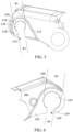
Fig. 5 is a right side view of the left wheel support. -
Fig. 6 is a left side view of the right wheel support. -
Fig. 7 is a left side view of a universal derailleur hanger. -
Fig. 8 is a section view taken along line 8-8 inFig. 2 . -
Fig. 9 is a left rear perspective view of rear wheel supports with a solid axle internal gear hub. -
Fig. 10 is a left rear exploded view of the assembly shown inFig. 9 . -
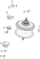
Fig. 11 is a right rear exploded view of the assembly shown inFig. 9 . -
Fig. 12 is an enlarged perspective view of a left end of a solid axle of the assembly shown inFig. 9 -
Fig. 13 is a right side view of a left spacer of the assembly inFig. 9 . -
Fig. 14 is a left rear perspective view of a right spacer assembly. -
Fig. 15 is a right rear perspective view of the right spacer assembly. -
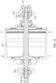
Fig. 16 is a section view taken along line 16-16 inFig. 9 . - Before any embodiments are explained in detail, it is to be understood that the present disclosure is not limited in its application to the details of construction and the arrangement of components set forth in the following description or illustrated in the following drawings. The disclosure is capable of other embodiments and of being practiced or of being carried out in various ways.
- In summary, the present disclosure provides a bicycle comprising a front wheel, a rear wheel including a rear axle defining a wheel axis, and a frame supported on both the front wheel and the rear wheel. The frame includes a left wheel support and a right wheel support that are each adapted to receive and be supported by the rear axle. The left wheel support includes a left hole extending through the left wheel support in a direction parallel to the wheel axis, the left hole having a first width perpendicular to the wheel axis, and a left slot extending through the left wheel support and in communication with the left hole. The left slot has a second width smaller than the first width such that the left hole and left slot cooperatively form a left keyhole through the left wheel support. The right wheel support includes a right hole extending through the right wheel support in a direction parallel to the wheel axis, the right hole having a third width (e.g., larger than the first width) perpendicular to the wheel axis, and a right slot extending through the right wheel support and in communication with the right hole. The right slot has a fourth width (e.g., substantially the same as the second width) smaller than the third width such that the right hole and right slot cooperatively form a right keyhole through the right wheel support. In one embodiment, the bicycle further comprises a left spacer removably positioned in the left keyhole, the left spacer including a base portion (e.g., including a left axle hole with at least one drive flat) positioned in the left hole and a left torque arm positioned in the left slot. The bicycle may further comprise a right spacer including a right axle hole with at least one drive flat and a right torque arm removably positioned in the right slot. The right spacer may include an inner spacer including the torque arm and the right axle hole with two drive flats, and an outer spacer non-rotatably positioned between the inner spacer and the right wheel support. The outer spacer preferably includes an axle slot aligned with the right slot in the right wheel support.
- In summary, The present disclosure also provides a method of converting the above bicycle having a first wheel type with a first axle to a bicycle having a second wheel type. The method comprises removing the first axle from the frame and from the first wheel type; inserting a second axle of the second wheel type in the left keyhole; sliding a left spacer onto the second axle and into the left keyhole; positioning a left torque arm of the left spacer in the left slot; and tightening the second axle to the frame. In one embodiment, the method further includes sliding a right spacer onto the second axle and into the right keyhole, and positioning a right torque arm of the right spacer in the right slot.
-
Fig. 1 shows abicycle 10 that includes afront wheel 15, arear wheel 20, and aframe 25. Theframe 25 may include ahead tube 30, afront fork 35 rotationally supported by thehead tube 30, atop tube 40 connected to and extending rearward from thehead tube 30, and adown tube 45 connected to thehead tube 30 below thetop tube 40 and extending generally downward toward a bottom bracket (not shown) of theframe 25. Aseat tube 50 may extend upward from the bottom bracket and be connected to thetop tube 40, and a seat 55 may be supported by theseat tube 50. Thebicycle 10 may also include ahandlebar 60 for turning thefront wheel 15 via thefork 35, and theframe 25 may include arear frame triangle 65 having rear wheel supports that support therear wheel 20. In the illustrated embodiment, eachwheel hub 70, arim 75 supported by thehub 70 via spokes 80 (or other wheel reinforcement members), and a tire 90 that is engaged with therim 75. -
Figs. 2-7 illustrate a thruaxle wheel hub 70 having ahub axle 100 and athru axle 102 that support the rear wheel for rotation about awheel axis 103. The illustrated rear wheel supports of the frame include aleft wheel support 104 and aright wheel support 106 that are each adapted to receive and be supported by thethru axle 102. Theleft wheel support 104 may include a left insideface 110 and a left guidinggroove 112 to guide thehub axle 100 into the proper position on the left insideface 110. Theleft wheel support 104 may further include aleft keyhole 114 including aleft hole 116 and aleft slot 118. Theleft hole 116 may extend through theleft wheel support 104 in a direction parallel to thewheel axis 103 and have a first width W1 perpendicular to thewheel axis 103. Theleft slot 118 may extend through the left wheel support and be in communication with theleft hole 116. Theleft slot 118 may have a second width W2 that is smaller than the first width W1 such that theleft hole 116 andleft slot 118 cooperatively form theleft keyhole 114 through theleft wheel support 104. In the illustrated embodiment, the first width W1 is a diameter of about 12.2 mm and the second width W2 is about 8.2 mm. - In the illustrated embodiment, the
right wheel support 106 comprises aright keyhole 120 including aright hole 122 and aright slot 124. Theright hole 122 may extend through theright wheel support 106 in a direction parallel to thewheel axis 103 and have a third width W3 perpendicular to thewheel axis 103. Theright slot 124 may extend through theright wheel support 106 and be in communication with theright hole 122. Theright slot 124 may have a fourth width W4 smaller than the third width W3 such that theright hole 122 andright slot 124 cooperatively form theright keyhole 120 through theright wheel support 106. In the illustrated embodiment, the third width W3 is a diameter of about 20 mm, and the fourth width W4 is about 8.2 mm. - The bicycle illustrated in
Figs. 1-8 further includes a derailleur hanger 126 (Fig. 2 ) secured to theright wheel support 106. The illustratedderailleur hanger 126 is a universal derailleur hanger ("UDH") having aninner hanger part 128 threaded with anouter screw 130 with theright wheel support 106 sandwiched in between. Theinner hanger part 128 may include acylindrical portion 131 dimensioned to be snugly positioned in theright hole 122 of theright wheel support 106, the cylindrical part having an internal thread dimensioned to mate with external threads on theouter screw 130. Theinner hanger part 128 may further include a right insideface 132 and a right guiding groove 134 (Fig. 7 ) to guide thehub axle 100 into the proper position on the right insideface 132. Theinner hanger part 128 may further include a threadedderailleur hole 136 for receiving and supporting a rear derailleur 138 (Fig. 1 ). Theouter screw 130 may further include a threadedopening 137 dimensioned to mate with a threadedend 139 of the thruaxle 102. - An
outer perimeter 140 of theinner hanger part 128 engages with acylindrical boss 186 on theright wheel support 106 to limit rotation of thederailleur hanger 126 relative to the frame. With thederailleur hanger 126 mounted to theright wheel support 106, the distance between the left insideface 110 of theleft wheel support 104 and the right insideface 132 of thederailleur hanger 126 defines a hub spacing of about 148 mm. - In the configuration of
Figs 2-8 , a rear wheel having a thruaxle hub 70 is slid in between the right and left wheel supports 104,106 so that thehub axle 100 rests in the right and left guiding grooves 112,134. The wheel and thruaxle hub 70 may then be moved upward until thehub axle 100 is positioned between the left and right inside faces 110,132. The thruaxle 102 may then be inserted through theleft wheel support 104 andhub axle 100 and then threaded into theouter screw 130 of thederailleur hanger 126. Tightening the thruaxle 102 to theouter screw 130 secures the rear wheel to the frame. -
Figs. 9-12 illustrated the same bicycle frame and wheel supports 104,106, but with different inserts to permit the securing of an IGH wheel having anIGH hub 150 andIGH axle 152. The illustratedIGH axle 152 has an OLD of 148 mm, and each end of theIGH axle 152 has a threaded diameter D1 of 10 mm with opposingparallel flats 153 spaced from each other to define a width W5 of about 8 mm. - In this embodiment, the bicycle includes a
left spacer 154 removably positioned in theleft keyhole 114 from the left side. More specifically, theleft spacer 154 includes abase portion 156 snugly positioned in theleft hole 116 and aleft torque arm 158 snugly positioned in theleft slot 118 and having a thickness T1 of about 8 mm. Thebase portion 156 of theleft spacer 154 may include anaxle hole 160 having a generallycylindrical portion 162 with a diameter D2 of about 10.2 mm and opposingdrive flats 164 that are spaced from each other by a width W6 of about 8.2 mm to thereby facilitate insertion of theIGH axle 152 into theaxle hole 160. Aleft nut 166 may be threaded onto the left end of theIGH axle 152 to secure the axle to theleft spacer 154 and leftwheel support 104. - As illustrated in
Figs. 6-9 , the bicycle may further include aright spacer 170 removably positioned in theright keyhole 120 on the inner side of the wheel support and aright nut 172 removably position in theright hole 122 from the outer side of the wheel support. The illustratedright spacer 170 comprises two parts: anouter spacer 174 and aninner spacer 176. Theouter spacer 174 may include acylindrical protrusion 178 adapted to fit in theright hole 122 and anouter perimeter 180 dimensioned to mate with therecess 142 on the inner face of theright wheel support 106. Rotation of theouter spacer 174 is further limited by the engagement of the cylindrical boss in asemicylindrical notch 184, and theouter spacer 174 may be secured to the inside face of theright wheel support 106 using ascrew 182 threaded into thecylindrical boss 186. Theouter spacer 174 may further include anaxle slot 188 aligned with theright slot 124 in theright wheel support 106. Theaxle slot 188 may have a width W7 of about 8.2 mm to receive the portion of the IGH axle having theparallel flats 153. - In the illustrated embodiment, the
inner spacer 176 includes aright torque arm 190 removably positioned in theright slot 124 and anouter perimeter 192 dimensioned to mate with arecess 194 on an inner face of theouter spacer 174 to limit rotation of theinner spacer 176 relative to theouter spacer 174. Theright torque arm 190 may have a thickness T2 of about 8 mm to facilitate removable insertion into theright slot 124 of theright keyhole 120. Theinner spacer 176 may further include anaxle hole 196 having a generally cylindrical portion 198 with a diameter of about 10.2 mm and opposing drive flats 200 that are spaced from each other by a width of about 8.2 mm to thereby facilitate insertion of theIGH axle 152 into theaxle hole 196. Aninside face 202 of theinner spacer 176 may provide a surface against which theIGH axle 152 can be tightened. - The
right nut 172 may include acylindrical portion 204 adapted to be removably inserted into theright hole 122 of theright keyhole 120, and alarger portion 206 that limits the amount of insertion of theright nut 172 into theright hole 122. Thecylindrical portion 204 may include a threadedopening 208 dimensioned to be threaded onto a threaded end of theIGH axle 152. - With the
left spacer 154 andright spacer 170 mounted to the wheel supports 104,106 as shown inFigs. 6-9 , the distance between the left insideface 110 of theleft wheel support 104 and theinside face 202 of theright spacer 170 defines an OLD hub spacing of about 148 mm. - In the configuration of
Figs. 6-9 , theouter spacer 174 may be attached in the appropriate position on the inside face of the right wheel support 106 (e.g., using thescrew 182 inserted through thenotch 184 and into a threadedboss 186 in the right wheel support 106). Theinner spacer 176 may then slide onto the right side of theIGH axle 152. The entire IGH hub 150 (with IGH axle 152) may then slide into the left and right keyholes 114,120 in the right and left wheel supports 104, 106. This results in theinner spacer 176 sliding in therecess 194 of theouter spacer 174. Theleft spacer 154 may then slide over the left end of theIGH axle 152 until theleft spacer 154 is fully seated into theleft keyhole 114. Theleft nut 166 andright nut 172 may then be threaded onto the left end and right end of theIGH axle 152, respectively. Tightening of theleft nut 166 andright nut 172 may result in securement of theIGH hub 150 to the left and right wheel supports 104,106. - In can be appreciated from the above that, by using different parts and spacers, the above-described wheel supports can be selectively adapted to be used with either a thru axle wheel or an IGH wheel. For example, to make the bicycle frame suitable for a thru
axle 102, theUDH 126 is secured to theright wheel support 106 by inserting thecylindrical portion 131 of theinner hanger part 128 into theright hole 122 of theright wheel support 106 and then threading theouter screw 130 into theinner hanger part 128 with theright wheel support 106 sandwiched in between. The wheel with the thruaxle wheel hub 70 is them slid up in between the left and right wheel supports 104,106, and the thruaxle 120 is inserted from the left and threaded securely into theouter screw 130. - To convert the thru axle arrangement to an IGH arrangement, the thru
axle 102 is unthreaded and removed, the wheel is slid downward from between the wheel supports 104,106, and theouter screw 130 is unthreaded from theinner hanger part 128 to permit the UDH to be completely removed from theright wheel support 106. This leaves the wheel supports 104,106 bare and without any spacers. - Next, the
cylindrical protrusion 178 of theouter spacer 174 is positioned in theright hole 122 of theright wheel support 106, and thescrew 182 is used to secure theouter spacer 174 to theright wheel support 106. Theinner spacer 176 is then slid onto the right side of theIGH axle 152, and the entire wheel withIGH hub 150 may then slide into the left and right keyholes 114,120 in the right and left wheel supports 104,106. This results in theinner spacer 176 sliding into therecess 194 of theouter spacer 174. Theleft spacer 154 may then slide over the left end of theIGH axle 152 until theleft spacer 154 is seated into theleft keyhole 114. Theleft nut 166 andright nut 172 may then be threaded onto the left end and right end of theIGH axle 152, respectively. Tightening of theleft nut 166 andright nut 172 may result in securement of theIGH hub 150 to the left and right wheel supports 104, 106. - In some examples, and in general, the
UDH 126 may be replaced by, or transformed into, one or more spacers (e.g., blank spacers) that fill the volume of theUDH 126 in configurations where having a derailleur may be undesirable. For example, a spacer or spacers may be used for an axle hub (e.g., for the thruaxle wheel hub 70, and/or other axle hubs). The spacers may, for example, be spacers such as those described above, or other spacers. - When used in this specification and claims, the terms "comprises" and "comprising" and variations thereof mean that the specified features, steps or integers are included. The terms are not to be interpreted to exclude the presence of other features, steps or components.
- The invention may also broadly consist in the parts, elements, steps, examples and/or features referred to or indicated in the specification individually or collectively in any and all combinations of two or more said parts, elements, steps, examples and/or features. In particular, one or more features in any of the embodiments described herein may be combined with one or more features from any other embodiment(s) described herein.
- Protection may be sought for any features disclosed in any one or more published documents referenced herein in combination with the present disclosure.
- Although certain example embodiments of the invention have been described, the scope of the appended claims is not intended to be limited solely to these embodiments. The claims are to be construed literally, purposively, and/or to encompass equivalents.
- Representative features are set out in the following clauses, which stand alone or may be combined, in any combination, with one or more features disclosed in the text and/or drawings of the specification.
- Clause 1: A bicycle comprising:
- a front wheel;
- a rear wheel including a rear axle defining a wheel axis; and
- a frame supported on both the front wheel and the rear wheel, the frame including a left wheel support and a right wheel support that are each adapted to receive and be supported by the rear axle,
- wherein the left wheel support includes:
- a left hole extending through the left wheel support in a direction parallel to the wheel axis, the left hole having a first width perpendicular to the wheel axis; and
- a left slot extending through the left wheel support and in communication with the left hole, the left slot having a second width smaller than the first width such that the left hole and left slot cooperatively form a left keyhole through the left wheel support,
- wherein the right wheel support includes:
- a right hole extending through the right wheel support in a direction parallel to the wheel axis, the right hole having a third width perpendicular to the wheel axis; and
- a right slot extending through the right wheel support and in communication with the right hole, the right slot having a fourth width smaller than the third width such that the right hole and right slot cooperatively form a right keyhole through the right wheel support.
- Clause 2: A bicycle as defined in
clause 1, wherein the first width is smaller than the third width. - Clause 3: A bicycle as defined in
clause 1, wherein the second width is substantially the same as the fourth width. - Clause 4: A bicycle as defined in
clause 1, further comprising a left spacer removably positioned in the left keyhole, the left spacer including a base portion positioned in the left hole and a left torque arm positioned in the left slot. - Clause 5: A bicycle as defined in
clause 4, wherein the base portion includes an axle hole with a drive flat. - Clause 6: A bicycle as defined in clause 5, wherein the axle hole includes two opposing drive flats.
- Clause 7: A bicycle as defined in
clause 1, further comprising a right spacer including a right torque arm removably positioned in the right slot. - Clause 8: A bicycle as defined in clause 7, wherein the right spacer further includes a right axle hole having a drive flat.
- Clause 9: A bicycle as defined in
clause 8, wherein the right axle hole has two opposing drive flats. - Clause 10: A bicycle as defined in clause 9, wherein the right spacer includes:
- an inner spacer including the torque arm and the right axle hole with two drive flats; and
- an outer spacer non-rotatably positioned between the inner spacer and the right wheel support, the outer spacer including an axle slot aligned with the right slot in the right wheel support.
- Clause 11: A method of converting a bicycle having a first wheel type to a bicycle having a second wheel type, the method comprising:
- providing the bicycle having a frame supported on a first axle of the first wheel type, the first axle defining a wheel axis, the frame including a left wheel support and a right wheel support that are each adapted to receive and be supported by the first axle, wherein the left wheel support includes:
- a left hole extending through the left wheel support in a direction parallel to the wheel axis, the left hole having a first width perpendicular to the wheel axis; and
- a left slot extending through the left wheel support and in communication with the left hole, the left slot having a second width smaller than the first width such that the left hole and left slot cooperatively form a left keyhole through the left wheel support, and
- wherein the right wheel support includes:
- a right hole extending through the right wheel support in a direction parallel to the wheel axis, the right hole having a third width perpendicular to the wheel axis; and
- a right slot extending through the right wheel support and in communication with the right hole, the right slot having a fourth width smaller than the third width such that the right hole and right slot cooperatively form a right keyhole through the right wheel support;
- removing the first axle from the frame and from the first wheel type;
- inserting a second axle of the second wheel type in the left keyhole;
- sliding a left spacer onto the second axle and into the left keyhole, the left spacer including a base portion positioned in the left hole and a left torque arm positioned in the left slot; and
- tightening the second axle to the frame.
- providing the bicycle having a frame supported on a first axle of the first wheel type, the first axle defining a wheel axis, the frame including a left wheel support and a right wheel support that are each adapted to receive and be supported by the first axle, wherein the left wheel support includes:
- Clause 12: A method as defined in clause 11, further comprising sliding a right spacer onto the second axle and into the right keyhole, the right spacer including a right torque arm positioned in the right slot.
- Clause 13: A bicycle frame comprising:
- a left wheel support including:
- a left hole extending through the left wheel support in a direction parallel to the wheel axis, the left hole having a first width perpendicular to the wheel axis; and
- a left slot extending through the left wheel support and in communication with the left hole, the left slot having a second width smaller than the first width such that the left hole and left slot cooperatively form a left keyhole through the left wheel support,
- a right wheel support including:
- a right hole extending through the right wheel support in a direction parallel to the wheel axis, the right hole having a third width perpendicular to the wheel axis; and
- a right slot extending through the right wheel support and in communication with the right hole, the right slot having a fourth width smaller than the third width such that the right hole and right slot cooperatively form a right keyhole through the right wheel support.
- a left wheel support including:
- Clause 14: A bicycle as defined in clause 13, wherein the first width is smaller than the third width.
- Clause 15: A bicycle as defined in clause 13, wherein the second width is substantially the same as the fourth width.
- Clause 16: A bicycle as defined in clause 13, further comprising a left spacer removably positioned in the left keyhole, the left spacer including a base portion positioned in the left hole and a left torque arm positioned in the left slot.
- Clause 17: A bicycle as defined in
clause 16, wherein the base portion includes an axle hole with a drive flat. - Clause 18: A bicycle as defined in clause 13, further comprising a right spacer including a right torque arm removably positioned in the right slot.
- Clause 19: A bicycle as defined in clause 18, wherein the right spacer further includes a right axle hole having a drive flat.
- Clause 20: A bicycle as defined in clause 19, wherein the right spacer comprises:
- an inner spacer including the torque arm and the right axle hole; and
- an outer spacer non-rotatably positioned between the inner spacer and the right wheel support, the outer spacer including an axle slot aligned with the right slot in the right wheel support.
- Clause 21: A bicycle frame comprising:
- a left wheel support including:
- a left hole extending through the left wheel support in a direction parallel to the wheel axis, the left hole having a first width perpendicular to the wheel axis; and
- a left slot extending through the left wheel support and in communication with the left hole, the left slot having a second width smaller than the first width such that the left hole and left slot cooperatively form a left keyhole through the left wheel support,
- a right wheel support including:
- a right hole extending through the right wheel support in a direction parallel to the wheel axis, the right hole having a third width perpendicular to the wheel axis; and
- a right slot extending through the right wheel support and in communication with the right hole, the right slot having a fourth width smaller than the third width such that the right hole and right slot cooperatively form a right keyhole through the right wheel support.
- a left wheel support including:
- Clause 22: A bicycle frame as defined in clause 21, wherein the first width is smaller than the third width.
- Clause 23: A bicycle frame as defined in clause 21 or clause 22, wherein the second width is substantially the same as the fourth width.
- Clause 24: A bicycle frame as defined in any of clauses 21-23, further comprising a left spacer removably positioned in the left keyhole, the left spacer including a base portion positioned in the left hole and a left torque arm positioned in the left slot.
- Clause 25: A bicycle frame as defined in clause 24, wherein the base portion includes an axle hole with a drive flat.
- Clause 26: A bicycle frame as defined in any of clauses 21-25, further comprising a right spacer including a right torque arm removably positioned in the right slot.
- Clause 27: A bicycle frame as defined in clause 26, wherein the right spacer further includes a right axle hole having a drive flat.
- Clause 28: A bicycle frame as defined in clause 27, wherein the right spacer comprises:
- an inner spacer including the torque arm and the right axle hole; and
- an outer spacer non-rotatably positioned between the inner spacer and the right wheel support, the outer spacer including an axle slot aligned with the right slot in the right wheel support.
- Clause 29: A bicycle comprising:
- a front wheel;
- a rear wheel including a rear axle defining a wheel axis; and
- the bicycle frame of any of clauses 21-28, wherein the bicycle frame is supported on both the front wheel and the rear wheel.
- Clause 30: A bicycle as defined in clause 29, further comprising a left spacer removably positioned in the left keyhole, the left spacer including a base portion positioned in the left hole and a left torque arm positioned in the left slot, wherein the base portion includes an axle hole with a drive flat.
- Clause 31: A bicycle as defined in
clause 30, wherein the axle hole includes two opposing drive flats. - Clause 32: A bicycle as defined in any of clauses 29-31, further comprising a right spacer including a right torque arm removably positioned in the right slot, wherein the right spacer further includes a right axle hole having a drive flat.
- Clause 33: A bicycle as defined in clause 32, wherein the right axle hole has two opposing drive flats.
- Clause 34: A method of converting a bicycle having a first wheel type to a bicycle having a second wheel type, the method comprising:
- providing the bicycle having a frame supported on a first axle of the first wheel type, the first axle defining a wheel axis, the frame including a left wheel support and a right wheel support that are each adapted to receive and be supported by the first axle, wherein the left wheel support includes:
- a left hole extending through the left wheel support in a direction parallel to the wheel axis, the left hole having a first width perpendicular to the wheel axis; and
- a left slot extending through the left wheel support and in communication with the left hole, the left slot having a second width smaller than the first width such that the left hole and left slot cooperatively form a left keyhole through the left wheel support, and
- wherein the right wheel support includes:
- a right hole extending through the right wheel support in a direction parallel to the wheel axis, the right hole having a third width perpendicular to the wheel axis; and
- a right slot extending through the right wheel support and in communication with the right hole, the right slot having a fourth width smaller than the third width such that the right hole and right slot cooperatively form a right keyhole through the right wheel support;
- removing the first axle from the frame and from the first wheel type;
- inserting a second axle of the second wheel type in the left keyhole;
- sliding a left spacer onto the second axle and into the left keyhole, the left spacer including a base portion positioned in the left hole and a left torque arm positioned in the left slot; and
- tightening the second axle to the frame.
- providing the bicycle having a frame supported on a first axle of the first wheel type, the first axle defining a wheel axis, the frame including a left wheel support and a right wheel support that are each adapted to receive and be supported by the first axle, wherein the left wheel support includes:
- Clause 35: A method as defined in clause 34, further comprising sliding a right spacer onto the second axle and into the right keyhole, the right spacer including a right torque arm positioned in the right slot.
- Various features of the disclosure are set forth in the following claims.
Claims (15)
- A bicycle frame comprising:a left wheel support including:a left hole extending through the left wheel support in a direction parallel to the wheel axis, the left hole having a first width perpendicular to the wheel axis; anda left slot extending through the left wheel support and in communication with the left hole, the left slot having a second width smaller than the first width such that the left hole and left slot cooperatively form a left keyhole through the left wheel support,a right wheel support including:a right hole extending through the right wheel support in a direction parallel to the wheel axis, the right hole having a third width perpendicular to the wheel axis; anda right slot extending through the right wheel support and in communication with the right hole, the right slot having a fourth width smaller than the third width such that the right hole and right slot cooperatively form a right keyhole through the right wheel support.
- A bicycle frame as claimed in claim 1, wherein the first width is smaller than the third width.
- A bicycle frame as claimed in claim 1 or claim 2, wherein the second width is substantially the same as the fourth width.
- A bicycle frame as claimed in any of the preceding claims, further comprising a left spacer removably positioned in the left keyhole, the left spacer including a base portion positioned in the left hole and a left torque arm positioned in the left slot.
- A bicycle frame as claimed in claim 4, wherein the base portion includes an axle hole with a drive flat.
- A bicycle frame as claimed in any of the preceding claims, further comprising a right spacer including a right torque arm removably positioned in the right slot.
- A bicycle frame as claimed in claim 6, wherein the right spacer further includes a right axle hole having a drive flat.
- A bicycle frame as claimed in claim 7, wherein the right spacer comprises:an inner spacer including the torque arm and the right axle hole; andan outer spacer non-rotatably positioned between the inner spacer and the right wheel support, the outer spacer including an axle slot aligned with the right slot in the right wheel support.
- A bicycle comprising:a front wheel;a rear wheel including a rear axle defining a wheel axis; andthe bicycle frame of any of claims 1-8, wherein the bicycle frame is supported on both the front wheel and the rear wheel.
- A bicycle as claimed in claim 9, further comprising a left spacer removably positioned in the left keyhole, the left spacer including a base portion positioned in the left hole and a left torque arm positioned in the left slot, wherein the base portion includes an axle hole with a drive flat.
- A bicycle as claimed in claim 10, wherein the axle hole includes two opposing drive flats.
- A bicycle as claimed in any of claims 9-11, further comprising a right spacer including a right torque arm removably positioned in the right slot, wherein the right spacer further includes a right axle hole having a drive flat.
- A bicycle as claimed in claim 12, wherein the right axle hole has two opposing drive flats.
- A method of converting a bicycle having a first wheel type to a bicycle having a second wheel type, the method comprising:providing the bicycle having a frame supported on a first axle of the first wheel type, the first axle defining a wheel axis, the frame including a left wheel support and a right wheel support that are each adapted to receive and be supported by the first axle, wherein the left wheel support includes:a left hole extending through the left wheel support in a direction parallel to the wheel axis, the left hole having a first width perpendicular to the wheel axis; anda left slot extending through the left wheel support and in communication with the left hole, the left slot having a second width smaller than the first width such that the left hole and left slot cooperatively form a left keyhole through the left wheel support, andwherein the right wheel support includes:a right hole extending through the right wheel support in a direction parallel to the wheel axis, the right hole having a third width perpendicular to the wheel axis; anda right slot extending through the right wheel support and in communication with the right hole, the right slot having a fourth width smaller than the third width such that the right hole and right slot cooperatively form a right keyhole through the right wheel support;removing the first axle from the frame and from the first wheel type;inserting a second axle of the second wheel type in the left keyhole;sliding a left spacer onto the second axle and into the left keyhole, the left spacer including a base portion positioned in the left hole and a left torque arm positioned in the left slot; andtightening the second axle to the frame.
- A method as claimed in claim 14, further comprising sliding a right spacer onto the second axle and into the right keyhole, the right spacer including a right torque arm positioned in the right slot.
Applications Claiming Priority (1)
| Application Number | Priority Date | Filing Date | Title |
|---|---|---|---|
| US17/895,914 US20240067297A1 (en) | 2022-08-25 | 2022-08-25 | Bicycle frame with convertible wheel mount |
Publications (2)
| Publication Number | Publication Date |
|---|---|
| EP4328124A1 true EP4328124A1 (en) | 2024-02-28 |
| EP4328124B1 EP4328124B1 (en) | 2025-09-03 |
Family
ID=87845939
Family Applications (1)
| Application Number | Title | Priority Date | Filing Date |
|---|---|---|---|
| EP23193472.0A Active EP4328124B1 (en) | 2022-08-25 | 2023-08-25 | Bicycle frame with convertible wheel mount |
Country Status (2)
| Country | Link |
|---|---|
| US (1) | US20240067297A1 (en) |
| EP (1) | EP4328124B1 (en) |
Families Citing this family (4)
| Publication number | Priority date | Publication date | Assignee | Title |
|---|---|---|---|---|
| USD1028800S1 (en) * | 2022-08-22 | 2024-05-28 | Shenzhen Coswheel Technology Co., Ltd | Electric bicycle frame |
| USD1046697S1 (en) * | 2023-05-05 | 2024-10-15 | Shenzhen Kixin Electronics Co., Ltd | Bicycle |
| USD1079552S1 (en) * | 2023-05-18 | 2025-06-17 | Yong Zhang | Electric bicycle |
| USD1104877S1 (en) * | 2024-10-30 | 2025-12-09 | Guangdong Yadea Locomotive CO., LTD | Electric bicycle |
Citations (3)
| Publication number | Priority date | Publication date | Assignee | Title |
|---|---|---|---|---|
| US20160159427A1 (en) * | 2009-01-02 | 2016-06-09 | Raphael Schlanger | Vehicle wheel axle assembly |
| CN209126903U (en) * | 2018-09-21 | 2019-07-19 | 富实特实业(东莞)有限公司 | A kind of novel front fork |
| US20220144381A1 (en) * | 2020-02-07 | 2022-05-12 | Perrin Stacy Rodriguez | Bicycle belt or chain tensioner and internally geared hub conversion kit |
Family Cites Families (5)
| Publication number | Priority date | Publication date | Assignee | Title |
|---|---|---|---|---|
| US10112439B2 (en) * | 2009-12-30 | 2018-10-30 | Raphael Schlanger | Vehicle wheel axle assembly |
| US9308961B2 (en) * | 2013-11-27 | 2016-04-12 | Specialized Bicycle Components, Inc. | Bicycle frame with convertible dropouts |
| US20160039494A1 (en) * | 2014-08-08 | 2016-02-11 | Cycling Sports Group, Inc. | Bicycle with pivoting derailleur hanger |
| US20220324532A1 (en) * | 2021-04-07 | 2022-10-13 | REX ENTERPRISES, dba RAMBO BIKES | Method of attaching hubs to bicycle frame |
| TWI771110B (en) * | 2021-07-21 | 2022-07-11 | 富錡企業股份有限公司 | Quick disassembly structure for quick assembly |
-
2022
- 2022-08-25 US US17/895,914 patent/US20240067297A1/en active Pending
-
2023
- 2023-08-25 EP EP23193472.0A patent/EP4328124B1/en active Active
Patent Citations (3)
| Publication number | Priority date | Publication date | Assignee | Title |
|---|---|---|---|---|
| US20160159427A1 (en) * | 2009-01-02 | 2016-06-09 | Raphael Schlanger | Vehicle wheel axle assembly |
| CN209126903U (en) * | 2018-09-21 | 2019-07-19 | 富实特实业(东莞)有限公司 | A kind of novel front fork |
| US20220144381A1 (en) * | 2020-02-07 | 2022-05-12 | Perrin Stacy Rodriguez | Bicycle belt or chain tensioner and internally geared hub conversion kit |
Also Published As
| Publication number | Publication date |
|---|---|
| US20240067297A1 (en) | 2024-02-29 |
| EP4328124B1 (en) | 2025-09-03 |
Similar Documents
| Publication | Publication Date | Title |
|---|---|---|
| EP4328124A1 (en) | Bicycle frame with convertible wheel mount | |
| US9308961B2 (en) | Bicycle frame with convertible dropouts | |
| US8424894B2 (en) | Bicycle frame dropouts and methods | |
| EP1958864A2 (en) | Bicycle wheel securing adapter and bicycle fork using the same | |
| DE102013204610B4 (en) | Torque element for a motorized bicycle | |
| US20220135171A1 (en) | Cargo bicycle conversion system | |
| US4809802A (en) | Structure for two-wheeled vehicle | |
| AU2011253357B2 (en) | Rear axle system for bicycle | |
| US7562943B2 (en) | Bicycle component securing structure | |
| USRE45684E1 (en) | Apparatus for twist-to-lock retention of a wheel | |
| EP2789530B1 (en) | Methods and apparatus for releasably supporting a vehicle wheel assembly | |
| US11511824B2 (en) | In-tube cavity and storage | |
| WO2012020303A2 (en) | Apparatus and method for routing bicycle control cables | |
| EP3444176B1 (en) | Bicycle frame tube having built-in motor, bicycle frame and electric bicycle | |
| EP3957578B1 (en) | Bicycle transport container | |
| EP2774833B1 (en) | Seat post mounting device and method | |
| CN116670019A (en) | handlebar with mounting structure | |
| EP3693255A1 (en) | Bicycle stand installation adapter and center stand equipped with same | |
| WO2008099386A1 (en) | Ready-to-ride bicycle carrier | |
| US20250382123A1 (en) | Devices for enclosing and/or transporting bicyles | |
| JP2021514903A (en) | Foldable bicycle frame | |
| EP2190727A1 (en) | Front wheel assembly for a folding bicycle | |
| JP2020069942A (en) | Wheel mounting auxiliary device |
Legal Events
| Date | Code | Title | Description |
|---|---|---|---|
| PUAI | Public reference made under article 153(3) epc to a published international application that has entered the european phase |
Free format text: ORIGINAL CODE: 0009012 |
|
| STAA | Information on the status of an ep patent application or granted ep patent |
Free format text: STATUS: THE APPLICATION HAS BEEN PUBLISHED |
|
| AK | Designated contracting states |
Kind code of ref document: A1 Designated state(s): AL AT BE BG CH CY CZ DE DK EE ES FI FR GB GR HR HU IE IS IT LI LT LU LV MC ME MK MT NL NO PL PT RO RS SE SI SK SM TR |
|
| STAA | Information on the status of an ep patent application or granted ep patent |
Free format text: STATUS: REQUEST FOR EXAMINATION WAS MADE |
|
| 17P | Request for examination filed |
Effective date: 20240828 |
|
| RBV | Designated contracting states (corrected) |
Designated state(s): AL AT BE BG CH CY CZ DE DK EE ES FI FR GB GR HR HU IE IS IT LI LT LU LV MC ME MK MT NL NO PL PT RO RS SE SI SK SM TR |
|
| GRAP | Despatch of communication of intention to grant a patent |
Free format text: ORIGINAL CODE: EPIDOSNIGR1 |
|
| STAA | Information on the status of an ep patent application or granted ep patent |
Free format text: STATUS: GRANT OF PATENT IS INTENDED |
|
| RIC1 | Information provided on ipc code assigned before grant |
Ipc: B60B 27/02 20060101ALN20250310BHEP Ipc: B62M 9/125 20100101ALN20250310BHEP Ipc: B62K 13/00 20060101ALI20250310BHEP Ipc: B62K 19/30 20060101ALI20250310BHEP Ipc: B62K 25/02 20060101AFI20250310BHEP |
|
| INTG | Intention to grant announced |
Effective date: 20250324 |
|
| GRAS | Grant fee paid |
Free format text: ORIGINAL CODE: EPIDOSNIGR3 |
|
| GRAA | (expected) grant |
Free format text: ORIGINAL CODE: 0009210 |
|
| STAA | Information on the status of an ep patent application or granted ep patent |
Free format text: STATUS: THE PATENT HAS BEEN GRANTED |
|
| AK | Designated contracting states |
Kind code of ref document: B1 Designated state(s): AL AT BE BG CH CY CZ DE DK EE ES FI FR GB GR HR HU IE IS IT LI LT LU LV MC ME MK MT NL NO PL PT RO RS SE SI SK SM TR |
|
| REG | Reference to a national code |
Ref country code: CH Ref legal event code: EP |
|
| REG | Reference to a national code |
Ref country code: DE Ref legal event code: R096 Ref document number: 602023006317 Country of ref document: DE |
|
| REG | Reference to a national code |
Ref country code: IE Ref legal event code: FG4D |
|
| REG | Reference to a national code |
Ref country code: NL Ref legal event code: MP Effective date: 20250903 |
|
| PG25 | Lapsed in a contracting state [announced via postgrant information from national office to epo] |
Ref country code: NO Free format text: LAPSE BECAUSE OF FAILURE TO SUBMIT A TRANSLATION OF THE DESCRIPTION OR TO PAY THE FEE WITHIN THE PRESCRIBED TIME-LIMIT Effective date: 20251203 |
|
| REG | Reference to a national code |
Ref country code: LT Ref legal event code: MG9D |
|
| PG25 | Lapsed in a contracting state [announced via postgrant information from national office to epo] |
Ref country code: FI Free format text: LAPSE BECAUSE OF FAILURE TO SUBMIT A TRANSLATION OF THE DESCRIPTION OR TO PAY THE FEE WITHIN THE PRESCRIBED TIME-LIMIT Effective date: 20250903 |
|
| PG25 | Lapsed in a contracting state [announced via postgrant information from national office to epo] |
Ref country code: HR Free format text: LAPSE BECAUSE OF FAILURE TO SUBMIT A TRANSLATION OF THE DESCRIPTION OR TO PAY THE FEE WITHIN THE PRESCRIBED TIME-LIMIT Effective date: 20250903 |
|
| PG25 | Lapsed in a contracting state [announced via postgrant information from national office to epo] |
Ref country code: GR Free format text: LAPSE BECAUSE OF FAILURE TO SUBMIT A TRANSLATION OF THE DESCRIPTION OR TO PAY THE FEE WITHIN THE PRESCRIBED TIME-LIMIT Effective date: 20251204 |
|
| PG25 | Lapsed in a contracting state [announced via postgrant information from national office to epo] |
Ref country code: SE Free format text: LAPSE BECAUSE OF FAILURE TO SUBMIT A TRANSLATION OF THE DESCRIPTION OR TO PAY THE FEE WITHIN THE PRESCRIBED TIME-LIMIT Effective date: 20250903 |
|
| PG25 | Lapsed in a contracting state [announced via postgrant information from national office to epo] |
Ref country code: LV Free format text: LAPSE BECAUSE OF FAILURE TO SUBMIT A TRANSLATION OF THE DESCRIPTION OR TO PAY THE FEE WITHIN THE PRESCRIBED TIME-LIMIT Effective date: 20250903 |
|
| PG25 | Lapsed in a contracting state [announced via postgrant information from national office to epo] |
Ref country code: BG Free format text: LAPSE BECAUSE OF FAILURE TO SUBMIT A TRANSLATION OF THE DESCRIPTION OR TO PAY THE FEE WITHIN THE PRESCRIBED TIME-LIMIT Effective date: 20250903 Ref country code: PL Free format text: LAPSE BECAUSE OF FAILURE TO SUBMIT A TRANSLATION OF THE DESCRIPTION OR TO PAY THE FEE WITHIN THE PRESCRIBED TIME-LIMIT Effective date: 20250903 |
|
| PG25 | Lapsed in a contracting state [announced via postgrant information from national office to epo] |
Ref country code: RS Free format text: LAPSE BECAUSE OF FAILURE TO SUBMIT A TRANSLATION OF THE DESCRIPTION OR TO PAY THE FEE WITHIN THE PRESCRIBED TIME-LIMIT Effective date: 20251203 |
|
| PG25 | Lapsed in a contracting state [announced via postgrant information from national office to epo] |
Ref country code: ES Free format text: LAPSE BECAUSE OF FAILURE TO SUBMIT A TRANSLATION OF THE DESCRIPTION OR TO PAY THE FEE WITHIN THE PRESCRIBED TIME-LIMIT Effective date: 20250903 |
|
| REG | Reference to a national code |
Ref country code: AT Ref legal event code: MK05 Ref document number: 1832741 Country of ref document: AT Kind code of ref document: T Effective date: 20250903 |
|
| PG25 | Lapsed in a contracting state [announced via postgrant information from national office to epo] |
Ref country code: NL Free format text: LAPSE BECAUSE OF FAILURE TO SUBMIT A TRANSLATION OF THE DESCRIPTION OR TO PAY THE FEE WITHIN THE PRESCRIBED TIME-LIMIT Effective date: 20250903 |
|
| PG25 | Lapsed in a contracting state [announced via postgrant information from national office to epo] |
Ref country code: SM Free format text: LAPSE BECAUSE OF FAILURE TO SUBMIT A TRANSLATION OF THE DESCRIPTION OR TO PAY THE FEE WITHIN THE PRESCRIBED TIME-LIMIT Effective date: 20250903 |
|
| PG25 | Lapsed in a contracting state [announced via postgrant information from national office to epo] |
Ref country code: AT Free format text: LAPSE BECAUSE OF FAILURE TO SUBMIT A TRANSLATION OF THE DESCRIPTION OR TO PAY THE FEE WITHIN THE PRESCRIBED TIME-LIMIT Effective date: 20250903 |
|
| PG25 | Lapsed in a contracting state [announced via postgrant information from national office to epo] |
Ref country code: IT Free format text: LAPSE BECAUSE OF FAILURE TO SUBMIT A TRANSLATION OF THE DESCRIPTION OR TO PAY THE FEE WITHIN THE PRESCRIBED TIME-LIMIT Effective date: 20250903 |
|
| PG25 | Lapsed in a contracting state [announced via postgrant information from national office to epo] |
Ref country code: IS Free format text: LAPSE BECAUSE OF FAILURE TO SUBMIT A TRANSLATION OF THE DESCRIPTION OR TO PAY THE FEE WITHIN THE PRESCRIBED TIME-LIMIT Effective date: 20260103 |
|
| PG25 | Lapsed in a contracting state [announced via postgrant information from national office to epo] |
Ref country code: PT Free format text: LAPSE BECAUSE OF FAILURE TO SUBMIT A TRANSLATION OF THE DESCRIPTION OR TO PAY THE FEE WITHIN THE PRESCRIBED TIME-LIMIT Effective date: 20260105 Ref country code: CZ Free format text: LAPSE BECAUSE OF FAILURE TO SUBMIT A TRANSLATION OF THE DESCRIPTION OR TO PAY THE FEE WITHIN THE PRESCRIBED TIME-LIMIT Effective date: 20250903 |
|
| PG25 | Lapsed in a contracting state [announced via postgrant information from national office to epo] |
Ref country code: EE Free format text: LAPSE BECAUSE OF FAILURE TO SUBMIT A TRANSLATION OF THE DESCRIPTION OR TO PAY THE FEE WITHIN THE PRESCRIBED TIME-LIMIT Effective date: 20250903 Ref country code: SK Free format text: LAPSE BECAUSE OF FAILURE TO SUBMIT A TRANSLATION OF THE DESCRIPTION OR TO PAY THE FEE WITHIN THE PRESCRIBED TIME-LIMIT Effective date: 20250903 |