EP4328100A1 - Emergency brake method and system - Google Patents
Emergency brake method and system Download PDFInfo
- Publication number
- EP4328100A1 EP4328100A1 EP23186815.9A EP23186815A EP4328100A1 EP 4328100 A1 EP4328100 A1 EP 4328100A1 EP 23186815 A EP23186815 A EP 23186815A EP 4328100 A1 EP4328100 A1 EP 4328100A1
- Authority
- EP
- European Patent Office
- Prior art keywords
- brake
- braking
- service brake
- service
- vehicle
- Prior art date
- Legal status (The legal status is an assumption and is not a legal conclusion. Google has not performed a legal analysis and makes no representation as to the accuracy of the status listed.)
- Granted
Links
Images


Classifications
-
- B—PERFORMING OPERATIONS; TRANSPORTING
- B60—VEHICLES IN GENERAL
- B60T—VEHICLE BRAKE CONTROL SYSTEMS OR PARTS THEREOF; BRAKE CONTROL SYSTEMS OR PARTS THEREOF, IN GENERAL; ARRANGEMENT OF BRAKING ELEMENTS ON VEHICLES IN GENERAL; PORTABLE DEVICES FOR PREVENTING UNWANTED MOVEMENT OF VEHICLES; VEHICLE MODIFICATIONS TO FACILITATE COOLING OF BRAKES
- B60T1/00—Arrangements of braking elements, i.e. of those parts where braking effect occurs specially for vehicles
- B60T1/02—Arrangements of braking elements, i.e. of those parts where braking effect occurs specially for vehicles acting by retarding wheels
- B60T1/08—Arrangements of braking elements, i.e. of those parts where braking effect occurs specially for vehicles acting by retarding wheels using fluid or powdered medium
- B60T1/093—Arrangements of braking elements, i.e. of those parts where braking effect occurs specially for vehicles acting by retarding wheels using fluid or powdered medium in hydrostatic, i.e. positive displacement, retarders
-
- B—PERFORMING OPERATIONS; TRANSPORTING
- B60—VEHICLES IN GENERAL
- B60T—VEHICLE BRAKE CONTROL SYSTEMS OR PARTS THEREOF; BRAKE CONTROL SYSTEMS OR PARTS THEREOF, IN GENERAL; ARRANGEMENT OF BRAKING ELEMENTS ON VEHICLES IN GENERAL; PORTABLE DEVICES FOR PREVENTING UNWANTED MOVEMENT OF VEHICLES; VEHICLE MODIFICATIONS TO FACILITATE COOLING OF BRAKES
- B60T10/00—Control or regulation for continuous braking making use of fluid or powdered medium, e.g. for use when descending a long slope
- B60T10/02—Control or regulation for continuous braking making use of fluid or powdered medium, e.g. for use when descending a long slope with hydrodynamic brake
-
- B—PERFORMING OPERATIONS; TRANSPORTING
- B60—VEHICLES IN GENERAL
- B60T—VEHICLE BRAKE CONTROL SYSTEMS OR PARTS THEREOF; BRAKE CONTROL SYSTEMS OR PARTS THEREOF, IN GENERAL; ARRANGEMENT OF BRAKING ELEMENTS ON VEHICLES IN GENERAL; PORTABLE DEVICES FOR PREVENTING UNWANTED MOVEMENT OF VEHICLES; VEHICLE MODIFICATIONS TO FACILITATE COOLING OF BRAKES
- B60T10/00—Control or regulation for continuous braking making use of fluid or powdered medium, e.g. for use when descending a long slope
- B60T10/04—Control or regulation for continuous braking making use of fluid or powdered medium, e.g. for use when descending a long slope with hydrostatic brake
-
- B—PERFORMING OPERATIONS; TRANSPORTING
- B60—VEHICLES IN GENERAL
- B60T—VEHICLE BRAKE CONTROL SYSTEMS OR PARTS THEREOF; BRAKE CONTROL SYSTEMS OR PARTS THEREOF, IN GENERAL; ARRANGEMENT OF BRAKING ELEMENTS ON VEHICLES IN GENERAL; PORTABLE DEVICES FOR PREVENTING UNWANTED MOVEMENT OF VEHICLES; VEHICLE MODIFICATIONS TO FACILITATE COOLING OF BRAKES
- B60T13/00—Transmitting braking action from initiating means to ultimate brake actuator with power assistance or drive; Brake systems incorporating such transmitting means, e.g. air-pressure brake systems
- B60T13/10—Transmitting braking action from initiating means to ultimate brake actuator with power assistance or drive; Brake systems incorporating such transmitting means, e.g. air-pressure brake systems with fluid assistance, drive, or release
- B60T13/24—Transmitting braking action from initiating means to ultimate brake actuator with power assistance or drive; Brake systems incorporating such transmitting means, e.g. air-pressure brake systems with fluid assistance, drive, or release the fluid being gaseous
- B60T13/26—Compressed-air systems
- B60T13/38—Brakes applied by springs or weights and released by compressed air
-
- B—PERFORMING OPERATIONS; TRANSPORTING
- B60—VEHICLES IN GENERAL
- B60T—VEHICLE BRAKE CONTROL SYSTEMS OR PARTS THEREOF; BRAKE CONTROL SYSTEMS OR PARTS THEREOF, IN GENERAL; ARRANGEMENT OF BRAKING ELEMENTS ON VEHICLES IN GENERAL; PORTABLE DEVICES FOR PREVENTING UNWANTED MOVEMENT OF VEHICLES; VEHICLE MODIFICATIONS TO FACILITATE COOLING OF BRAKES
- B60T13/00—Transmitting braking action from initiating means to ultimate brake actuator with power assistance or drive; Brake systems incorporating such transmitting means, e.g. air-pressure brake systems
- B60T13/10—Transmitting braking action from initiating means to ultimate brake actuator with power assistance or drive; Brake systems incorporating such transmitting means, e.g. air-pressure brake systems with fluid assistance, drive, or release
- B60T13/66—Electrical control in fluid-pressure brake systems
-
- B—PERFORMING OPERATIONS; TRANSPORTING
- B60—VEHICLES IN GENERAL
- B60T—VEHICLE BRAKE CONTROL SYSTEMS OR PARTS THEREOF; BRAKE CONTROL SYSTEMS OR PARTS THEREOF, IN GENERAL; ARRANGEMENT OF BRAKING ELEMENTS ON VEHICLES IN GENERAL; PORTABLE DEVICES FOR PREVENTING UNWANTED MOVEMENT OF VEHICLES; VEHICLE MODIFICATIONS TO FACILITATE COOLING OF BRAKES
- B60T13/00—Transmitting braking action from initiating means to ultimate brake actuator with power assistance or drive; Brake systems incorporating such transmitting means, e.g. air-pressure brake systems
- B60T13/10—Transmitting braking action from initiating means to ultimate brake actuator with power assistance or drive; Brake systems incorporating such transmitting means, e.g. air-pressure brake systems with fluid assistance, drive, or release
- B60T13/66—Electrical control in fluid-pressure brake systems
- B60T13/68—Electrical control in fluid-pressure brake systems by electrically-controlled valves
- B60T13/686—Electrical control in fluid-pressure brake systems by electrically-controlled valves in hydraulic systems or parts thereof
-
- B—PERFORMING OPERATIONS; TRANSPORTING
- B60—VEHICLES IN GENERAL
- B60T—VEHICLE BRAKE CONTROL SYSTEMS OR PARTS THEREOF; BRAKE CONTROL SYSTEMS OR PARTS THEREOF, IN GENERAL; ARRANGEMENT OF BRAKING ELEMENTS ON VEHICLES IN GENERAL; PORTABLE DEVICES FOR PREVENTING UNWANTED MOVEMENT OF VEHICLES; VEHICLE MODIFICATIONS TO FACILITATE COOLING OF BRAKES
- B60T15/00—Construction arrangement, or operation of valves incorporated in power brake systems and not covered by groups B60T11/00 or B60T13/00
- B60T15/02—Application and release valves
- B60T15/04—Driver's valves
- B60T15/041—Driver's valves controlling auxiliary pressure brakes, e.g. parking or emergency brakes
-
- B—PERFORMING OPERATIONS; TRANSPORTING
- B60—VEHICLES IN GENERAL
- B60T—VEHICLE BRAKE CONTROL SYSTEMS OR PARTS THEREOF; BRAKE CONTROL SYSTEMS OR PARTS THEREOF, IN GENERAL; ARRANGEMENT OF BRAKING ELEMENTS ON VEHICLES IN GENERAL; PORTABLE DEVICES FOR PREVENTING UNWANTED MOVEMENT OF VEHICLES; VEHICLE MODIFICATIONS TO FACILITATE COOLING OF BRAKES
- B60T7/00—Brake-action initiating means
- B60T7/02—Brake-action initiating means for personal initiation
- B60T7/04—Brake-action initiating means for personal initiation foot actuated
- B60T7/042—Brake-action initiating means for personal initiation foot actuated by electrical means, e.g. using travel or force sensors
-
- B—PERFORMING OPERATIONS; TRANSPORTING
- B60—VEHICLES IN GENERAL
- B60T—VEHICLE BRAKE CONTROL SYSTEMS OR PARTS THEREOF; BRAKE CONTROL SYSTEMS OR PARTS THEREOF, IN GENERAL; ARRANGEMENT OF BRAKING ELEMENTS ON VEHICLES IN GENERAL; PORTABLE DEVICES FOR PREVENTING UNWANTED MOVEMENT OF VEHICLES; VEHICLE MODIFICATIONS TO FACILITATE COOLING OF BRAKES
- B60T8/00—Arrangements for adjusting wheel-braking force to meet varying vehicular or ground-surface conditions, e.g. limiting or varying distribution of braking force
- B60T8/17—Using electrical or electronic regulation means to control braking
- B60T8/176—Brake regulation specially adapted to prevent excessive wheel slip during vehicle deceleration, e.g. ABS
-
- B—PERFORMING OPERATIONS; TRANSPORTING
- B60—VEHICLES IN GENERAL
- B60T—VEHICLE BRAKE CONTROL SYSTEMS OR PARTS THEREOF; BRAKE CONTROL SYSTEMS OR PARTS THEREOF, IN GENERAL; ARRANGEMENT OF BRAKING ELEMENTS ON VEHICLES IN GENERAL; PORTABLE DEVICES FOR PREVENTING UNWANTED MOVEMENT OF VEHICLES; VEHICLE MODIFICATIONS TO FACILITATE COOLING OF BRAKES
- B60T8/00—Arrangements for adjusting wheel-braking force to meet varying vehicular or ground-surface conditions, e.g. limiting or varying distribution of braking force
- B60T8/18—Arrangements for adjusting wheel-braking force to meet varying vehicular or ground-surface conditions, e.g. limiting or varying distribution of braking force responsive to vehicle weight or load, e.g. load distribution
- B60T8/1881—Arrangements for adjusting wheel-braking force to meet varying vehicular or ground-surface conditions, e.g. limiting or varying distribution of braking force responsive to vehicle weight or load, e.g. load distribution characterised by failure-responsive means
-
- F—MECHANICAL ENGINEERING; LIGHTING; HEATING; WEAPONS; BLASTING
- F16—ENGINEERING ELEMENTS AND UNITS; GENERAL MEASURES FOR PRODUCING AND MAINTAINING EFFECTIVE FUNCTIONING OF MACHINES OR INSTALLATIONS; THERMAL INSULATION IN GENERAL
- F16D—COUPLINGS FOR TRANSMITTING ROTATION; CLUTCHES; BRAKES
- F16D57/00—Liquid-resistance brakes; Brakes using the internal friction of fluids or fluid-like media, e.g. powders
- F16D57/06—Liquid-resistance brakes; Brakes using the internal friction of fluids or fluid-like media, e.g. powders comprising a pump circulating fluid, braking being effected by throttling of the circulation
-
- B—PERFORMING OPERATIONS; TRANSPORTING
- B60—VEHICLES IN GENERAL
- B60T—VEHICLE BRAKE CONTROL SYSTEMS OR PARTS THEREOF; BRAKE CONTROL SYSTEMS OR PARTS THEREOF, IN GENERAL; ARRANGEMENT OF BRAKING ELEMENTS ON VEHICLES IN GENERAL; PORTABLE DEVICES FOR PREVENTING UNWANTED MOVEMENT OF VEHICLES; VEHICLE MODIFICATIONS TO FACILITATE COOLING OF BRAKES
- B60T2220/00—Monitoring, detecting driver behaviour; Signalling thereof; Counteracting thereof
- B60T2220/04—Pedal travel sensor, stroke sensor; Sensing brake request
-
- B—PERFORMING OPERATIONS; TRANSPORTING
- B60—VEHICLES IN GENERAL
- B60T—VEHICLE BRAKE CONTROL SYSTEMS OR PARTS THEREOF; BRAKE CONTROL SYSTEMS OR PARTS THEREOF, IN GENERAL; ARRANGEMENT OF BRAKING ELEMENTS ON VEHICLES IN GENERAL; PORTABLE DEVICES FOR PREVENTING UNWANTED MOVEMENT OF VEHICLES; VEHICLE MODIFICATIONS TO FACILITATE COOLING OF BRAKES
- B60T2270/00—Further aspects of brake control systems not otherwise provided for
- B60T2270/40—Failsafe aspects of brake control systems
- B60T2270/402—Back-up
Definitions
- the present invention relates to an emergency brake method and system.
- Vehicles equipped with a hydrostatic drive such as agricultural and work vehicles, are often used off-road vehicles on rough terrain, such as rocky and/or marshy terrain. Often, they also have to carry large loads, so the service brake can be severely stressed.
- the service brake comprises friction members designed to contact each other by developing frictional forces.
- a vehicle driven by a hydrostatic drive unit comprises an internal combustion engine which drives a variable displacement pump to supply pressurized oil to a hydraulic motor which drives at least one wheel.
- the service braking action is activated by the user of the vehicle to decrease speed or to stop the vehicle.
- the action of the parking brake typically guarantees the parking position of the vehicle and is controlled by a specific manual lever or button, provided on the dashboard of the vehicle.
- the parking brake can be intrinsically safe, SAHR from the Anglo-Saxon acronym “Spring applied hydraulically released brakes".
- SAHR Anglo-Saxon acronym "Spring applied hydraulically released brakes”.
- an elastic element pushes the brake towards the braking position and a pressurized diaphragm opposes the elastic action, disengaging the parking brake. Therefore, in the absence of pressurization, for example due to a fault, the parking brake is activated automatically.
- the engagement condition is the natural condition of the SAHR brake, while its disengagement is forced by means of a pressurized gas.
- the parking brake operates as an emergency brake in the event of a malfunction of the service brake.
- the parking brake is activated by means of a proportional valve, usually by an electronic controller, which is activated automatically when a fault is detected in the service brake.
- the controller activates the emergency brake to complement or replace the service brake.
- Figure 1 shows an example of an electro-hydraulic circuit that implements the SAHR brake as an emergency brake.
- the service brake pedal BP transmits its action to the so-called master piston SBP through which the service brake SB is commanded.
- a position sensor AS is associated with the brake pedal BP to detect the extent of the action exerted by the operator on the pedal BP.
- Fault detection means FD are operationally connected to the controller CU and monitor the operation of the service brake SB by means of a sensor BS and in the event of a malfunction inform the controller which activates a proportional valve PV according to the position measured by the sensor AS of the brake pedal travel.
- This sensor can be, for example, a pressure sensor associated with the hydraulic circuit of the service brake.
- a pump P feeds a pressure source R connected to the diaphragm of the SAHR via the proportional valve PV.
- the diaphragm is connected with the pressure source R, while the braking action provides for the proportional depressurization of the diaphragm of the SAHR with the position of the brake pedal.
- the object of the present invention is to propose a more efficient emergency brake method and system than those known.
- the basic idea of the present invention is to simultaneously activate the emergency braking performed by SAHR and the braking performed by the hydrostatic transmission.
- second component does not imply the presence of a “first” component. These terms are in fact used as labels to improve clarity and should not be understood in a limiting way.
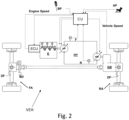
- a prime mover E generally an internal combustion engine, drives a variable displacement hydraulic pump HP in rotation, which powers a variable displacement hydraulic motor HM operatively connected to the hydraulic pump defining a so-called hydrostat HY, in which a forward hydraulic line F and a return hydraulic line R interconnect the hydraulic pump with the hydraulic motor.
- this transmission is referred to as a "series" hydraulic transmission, in the sense that the connection between the prime mover and the vehicle wheels occurs exclusively through the hydrostat.
- the displacement of the hydraulic pump is electrically controlled.
- there is a map of adjustments of the displacement of the hydraulic pump which allows to control the displacement of the latter as a function of the rotation speed of the prime mover.
- the relationship between the pump displacement and the speed of the prime mover is linear and the displacement grows with increasing speed.
- the displacement of the hydraulic motor is electrically controlled.
- the kinetic energy is therefore converted into pressure energy which is partially dissipated in the hydrostat and partially dissipated in the frictions of the prime mover which is driven into rotation by the hydraulic pump functioning as a hydraulic motor.
- Figure 3 shows time diagrams respectively, from top to bottom:
- the controller CU when the controller CU is configured to calculate information on the status of the service brake action in order to detect a fault of the service brake action and in the event of a fault detection it is configured to execute simultaneously the following operations:
- the hydrostatic drive VEH agricultural or work vehicle comprising:
- the controller is operatively connected with a proportional valve PV to activate the spring brake SAHR in proportion to the measure of the position of the brake pedal BP, measured by the sensor AS operatively associated with the service brake pedal.
- the controller is configured to adjust the braking torque in proportion to the position of the brake pedal BP, measured by means of the sensor AS operatively associated with the service brake pedal.
- the hydrostat has a braking capacity that decreases with the speed of the vehicle and in particular, this capacity is very modest for very low speeds, i.e. below 5 km/h.
- this capacity is very modest for very low speeds, i.e. below 5 km/h.
- the contribution of the SAHR becomes operational, creating a natural joint between the braking contributions of the hydrostat and the SAHR system.
- the fault detected on the service brake can be signaled to the operator by means of a warning light and/or an acoustic signal.
- a warning light and/or an acoustic signal can be signaled to the operator by means of a warning light and/or an acoustic signal.
- the braking performances do not undergo any significant variation.
- the fault can be detected in several ways, for example by comparing the rate of decrease of the vehicle speed with the position of the brake pedal.
- the fault is detected by means of a sensor BS associated with the hydraulic circuit to measure the pressure of the fluid inside it.
- the present invention can be advantageously carried out by means of a computer program which comprises coding means for carrying out one or more steps of the method, when this program is executed on a computer. Therefore, it is intended that the scope of protection extends to said computer program and further to computer readable means comprising a recorded message, said computer readable means comprising program coding means for carrying out one or more steps of the method, when said program is run on a computer. Implementation variants of the described non-limiting example are possible, without however departing from the scope of protection of the present invention, including all the equivalent embodiments for a person skilled in the art, to the content of the claims.
Landscapes
- Engineering & Computer Science (AREA)
- Mechanical Engineering (AREA)
- Transportation (AREA)
- General Engineering & Computer Science (AREA)
- Physics & Mathematics (AREA)
- Fluid Mechanics (AREA)
- Regulating Braking Force (AREA)
- Valves And Accessory Devices For Braking Systems (AREA)
Abstract
Description
- The present invention relates to an emergency brake method and system.
- Vehicles equipped with a hydrostatic drive, such as agricultural and work vehicles, are often used off-road vehicles on rough terrain, such as rocky and/or marshy terrain. Often, they also have to carry large loads, so the service brake can be severely stressed. The service brake comprises friction members designed to contact each other by developing frictional forces.
- Typically, a vehicle driven by a hydrostatic drive unit comprises an internal combustion engine which drives a variable displacement pump to supply pressurized oil to a hydraulic motor which drives at least one wheel.
- Typically, the service braking action is activated by the user of the vehicle to decrease speed or to stop the vehicle. While, the action of the parking brake typically guarantees the parking position of the vehicle and is controlled by a specific manual lever or button, provided on the dashboard of the vehicle. In heavy vehicles, including those with hydrostatic transmission, the parking brake can be intrinsically safe, SAHR from the Anglo-Saxon acronym "Spring applied hydraulically released brakes". In this type of brakes, an elastic element pushes the brake towards the braking position and a pressurized diaphragm opposes the elastic action, disengaging the parking brake. Therefore, in the absence of pressurization, for example due to a fault, the parking brake is activated automatically. In other words, the engagement condition is the natural condition of the SAHR brake, while its disengagement is forced by means of a pressurized gas.
- It is known that the parking brake operates as an emergency brake in the event of a malfunction of the service brake. In such an application, the parking brake is activated by means of a proportional valve, usually by an electronic controller, which is activated automatically when a fault is detected in the service brake. The controller activates the emergency brake to complement or replace the service brake.
Figure 1 shows an example of an electro-hydraulic circuit that implements the SAHR brake as an emergency brake. - The service brake pedal BP transmits its action to the so-called master piston SBP through which the service brake SB is commanded.
- A position sensor AS is associated with the brake pedal BP to detect the extent of the action exerted by the operator on the pedal BP.
- Fault detection means FD are operationally connected to the controller CU and monitor the operation of the service brake SB by means of a sensor BS and in the event of a malfunction inform the controller which activates a proportional valve PV according to the position measured by the sensor AS of the brake pedal travel. This sensor can be, for example, a pressure sensor associated with the hydraulic circuit of the service brake.
- A pump P feeds a pressure source R connected to the diaphragm of the SAHR via the proportional valve PV. In the deactivation conditions of the proportional valve PV, the diaphragm is connected with the pressure source R, while the braking action provides for the proportional depressurization of the diaphragm of the SAHR with the position of the brake pedal.
- However, the reaction times of the service brakes are long. It has been observed that the braking action follows the action on the brake pedal with a minimum delay of more than 1.5 seconds. When the pedal is only partially depressed, the delay of action, on the other hand, can exceed 2.5 seconds. Evidently, with this delay, the operator perceives a situation of helplessness and danger, as the vehicle does not respond adequately to commands.
- If not specifically excluded in the detailed description that follows, what is described in this chapter is to be considered as an integral part of the detailed description.
- The object of the present invention is to propose a more efficient emergency brake method and system than those known.
- The basic idea of the present invention is to simultaneously activate the emergency braking performed by SAHR and the braking performed by the hydrostatic transmission.
- The dependent claims describe preferred variants of the invention, forming an integral part of this description.
- Further objects and advantages of the present invention will become clear from the following detailed description of an example of its embodiment (and its variants) and from the annexed drawings given purely for explanatory and non-limiting purposes, in which:
-
Figure 1 shows the set of a service brake system with an emergency and parking brake system of the SAHR type according to the known art; -
Figure 2 shows an electro-mechanical diagram of a propulsion system based on a hydrostatic transmission, according to the present invention, of a work vehicle comprising the braking systems according toFigure 1 ; -
Figure 3 shows a time diagram showing the combination of the braking action of the SAHR system and hydrostatic braking. - The same reference numbers and letters in the figures identify the same elements or components.
- In the context of this description, the term "second" component does not imply the presence of a "first" component. These terms are in fact used as labels to improve clarity and should not be understood in a limiting way.
- The elements and features illustrated in the various preferred embodiments, including the drawings, can be combined with each other without however departing from the scope of this application as described below.
- With reference to
Figure 1 , a prime mover E, generally an internal combustion engine, drives a variable displacement hydraulic pump HP in rotation, which powers a variable displacement hydraulic motor HM operatively connected to the hydraulic pump defining a so-called hydrostat HY, in which a forward hydraulic line F and a return hydraulic line R interconnect the hydraulic pump with the hydraulic motor. - To better define the diagram in
Figure 1 , this transmission is referred to as a "series" hydraulic transmission, in the sense that the connection between the prime mover and the vehicle wheels occurs exclusively through the hydrostat. - The displacement of the hydraulic pump is electrically controlled. Generally, there is a map of adjustments of the displacement of the hydraulic pump which allows to control the displacement of the latter as a function of the rotation speed of the prime mover. Typically, the relationship between the pump displacement and the speed of the prime mover is linear and the displacement grows with increasing speed.
- The displacement of the hydraulic motor is electrically controlled.
- Generally, there is a map of adjustments of the displacement of the hydraulic motor that allows to control the relative displacement according to the pressure that is generated on the forward F and return R hydraulic lines or according to the speed of the vehicle and according to the load perceived by the hydraulic motor.
- It is possible to control the hydrostat in order to achieve hydrostatic braking.
- This can be achieved, for example, by increasing the displacement of the motor and reducing the displacement of the pump. Under such conditions, the engine HM acts as a hydraulic pump, while the hydraulic pump HP acts as a hydraulic motor.
- The kinetic energy is therefore converted into pressure energy which is partially dissipated in the hydrostat and partially dissipated in the frictions of the prime mover which is driven into rotation by the hydraulic pump functioning as a hydraulic motor.
-
Figure 3 shows time diagrams respectively, from top to bottom: - Of the action on the brake pedal "Brake Pedal action";
- The braking action exerted by the SAHR system "SAHR BF" in response to the action on the brake pedal;
- The braking action "HY BF" exerted by the hydrostatic transmission in response to the action on the brake pedal;
- The speed of the vehicle "VEH DEC SAHR" thanks to the braking contribution of the SAHR system alone, in response to the action on the brake pedal;
- The vehicle speed "VEH DEC COMB" thanks to the combined braking action of the SAHR system and of the hydrostatic transmission, in response to the action on the brake pedal. It is important to note that not only the vehicle stop earlier, but also the braking is more gradual and above all it starts much earlier than the intervention of the SAHR system alone, avoiding a feeling of helplessness on the operator.
- According to the present invention, when the controller CU is configured to calculate information on the status of the service brake action in order to detect a fault of the service brake action and in the event of a fault detection it is configured to execute simultaneously the following operations:
- Hydrostat control to achieve hydrostatic braking,
- Control of the SAHR brake to realize an emergency braking. Since the hydrostat has reaction times lower than the SAHR braking system, then the operator does not perceive the braking delay typical of the failure condition of emergency braking systems based exclusively on the SAHR system.
- In other words, the hydrostatic drive VEH agricultural or work vehicle, comprising:
- a hydrostatic transmission unit HY, suitable for propulsion of the VEH vehicle;
- a user interface BP of the service brake SB, adapted to receive a brake request from a user of the vehicle VEH;
- at least one service brake system SB comprising friction elements arranged to brake the vehicle VEH in response to the braking request acquired through the service brake BP user interface;
- at least one SAHR spring-loaded parking brake system, capable of exerting an intrinsically safe parking brake action;
- a controller CU operatively connected with the user interface, with the service brake system SB and with the SAHR spring parking brake system and configured to detect a service brake failure;
- According to the invention,
- the hydrostatic transmission unit HY is suitable for creating a hydrostatic braking system to exert a braking action on the vehicle and
- the controller CU is configured to automatically and simultaneously activate the SAHR spring-loaded parking brake system and said hydrostatic braking system to complement said service brake in response to said brake request by the user in service brake failure conditions.
- The controller is operatively connected with a proportional valve PV to activate the spring brake SAHR in proportion to the measure of the position of the brake pedal BP, measured by the sensor AS operatively associated with the service brake pedal.
- The controller is configured to adjust the braking torque in proportion to the position of the brake pedal BP, measured by means of the sensor AS operatively associated with the service brake pedal.
- It is worth highlighting that the hydrostat has a braking capacity that decreases with the speed of the vehicle and in particular, this capacity is very modest for very low speeds, i.e. below 5 km/h. However, after the vehicle has reduced its speed due to the braking effect of the hydrostat, the contribution of the SAHR becomes operational, creating a natural joint between the braking contributions of the hydrostat and the SAHR system.
- In other words, the contribution of the hydrostatic braking system and the contribution of the SAHR system combine over time, although they are activated approximately simultaneously.
- The fault detected on the service brake can be signaled to the operator by means of a warning light and/or an acoustic signal. However, thanks to the present invention the braking performances do not undergo any significant variation.
- The fault can be detected in several ways, for example by comparing the rate of decrease of the vehicle speed with the position of the brake pedal. Generally, when the service brake is equipped with a hydraulic circuit, the fault is detected by means of a sensor BS associated with the hydraulic circuit to measure the pressure of the fluid inside it.
- The present invention can be advantageously carried out by means of a computer program which comprises coding means for carrying out one or more steps of the method, when this program is executed on a computer. Therefore, it is intended that the scope of protection extends to said computer program and further to computer readable means comprising a recorded message, said computer readable means comprising program coding means for carrying out one or more steps of the method, when said program is run on a computer. Implementation variants of the described non-limiting example are possible, without however departing from the scope of protection of the present invention, including all the equivalent embodiments for a person skilled in the art, to the content of the claims.
- From the above description, the person skilled in the art is able to realize the object of the invention without introducing further construction details.
Claims (8)
- Hydrostatic drive agricultural or work vehicle (VEH), comprising:- a hydrostatic transmission unit (HY), suitable for vehicle propulsion (VEH);- at least one service brake system (SB) comprising friction elements arranged to brake the vehicle (VEH) in response to a braking request;- a user interface (BP) of the service brake (SB), suitable for receiving said brake request from a vehicle (VEH) user;- at least one spring-loaded parking brake system SAHR (SAHR), capable of exerting a parking brake action;- a controller (CU) operatively connected with said user interface, with said service brake system (SB) and with said spring parking brake system SAHR and configured to detect a failure of the service brake;
wherein said controller (CU) is configured to automatically activate said SAHR spring-loaded parking brake system to complement said service brake system to perform an emergency braking in response to a brake request by the user in conditions of service brake failure;
the vehicle being characterized in that- the hydrostatic transmission unit (HY) is configured to create a hydrostatic braking system to exert a braking action on the vehicle and in that- said controller (CU) is configured to automatically and simultaneously activate said SAHR spring-loaded parking brake system and said hydrostatic braking system to complement said service brake in response to said braking request by the user to perform the emergency braking in response to said brake request by the user in service brake failure conditions. - Vehicle according to claim 1, wherein said service brake (SB) user interface is a brake pedal (BP) having a stroke, so that the service brake request depends on the position of said brake pedal and wherein at least a first sensor (AS) is associated with the brake pedal to detect the current position of the brake pedal, and wherein said controller is operatively connected with said first sensor (AS) to calculate said service braking request.
- Vehicle according to claim 1 or 2, comprising at least a second sensor (BS) associated with said service brake, able to detect at least one operating parameter of said service brake and wherein said controller (CU) is operatively connected with said second sensor (BS) and comprises means for detecting a fault (FD) of the service brake on the basis of a signal, generated by said second sensor (BS), function of said at least one operating parameter.
- Vehicle according to any one of the preceding claims 2 or 3, wherein said service brake (SB) comprises friction material adapted to be applied by means of a thrust force proportional to said position of the brake pedal.
- Vehicle according to any one of the preceding claims 2 - 4, wherein said SAHR spring-loaded parking brake comprises spring-forced friction material and comprises hydraulic or pneumatic release means arranged to release the parking brake and wherein the parking brake comprises a proportional valve (PV) operatively connected to said controller (CU) and wherein the controller is configured to modulate the activation of the hydraulic or pneumatic release of said spring parking brake as a function of said stroke of said brake pedal in response to said brake request by the user under service brake failure conditions.
- A method of exerting an emergency braking action in order to slow and/or stop a hydrostatic drive (HY) vehicle (VEH) during a service brake (SB) failure condition, where the brake service includes friction elements arranged to brake the vehicle (VEH) in response to a brake request; the method including, in the event of a service brake failure:- a first step of automatically activating a SAHR spring parking brake system (SAHR),- a second step to automatically activate hydrostatic braking,to exert said braking action, to complement said service brake system, by carrying out said emergency braking, and wherein said first and second steps are performed automatically and simultaneously in response to said braking request.
- The method according to claim 6, comprising a preliminary step of monitoring at least one operating parameter of the service brake to detect a failure of the service brake.
- Method according to claim 6 or 7, wherein said activation of the spring-loaded parking brake system and said hydrostatic braking are function of a current position of a service brake pedal through which said request for braking is exerted.
Applications Claiming Priority (1)
| Application Number | Priority Date | Filing Date | Title |
|---|---|---|---|
| IT102022000015663A IT202200015663A1 (en) | 2022-07-26 | 2022-07-26 | Emergency brake method and system |
Publications (2)
| Publication Number | Publication Date |
|---|---|
| EP4328100A1 true EP4328100A1 (en) | 2024-02-28 |
| EP4328100B1 EP4328100B1 (en) | 2025-04-02 |
Family
ID=83691699
Family Applications (1)
| Application Number | Title | Priority Date | Filing Date |
|---|---|---|---|
| EP23186815.9A Active EP4328100B1 (en) | 2022-07-26 | 2023-07-20 | Emergency brake method and system |
Country Status (2)
| Country | Link |
|---|---|
| EP (1) | EP4328100B1 (en) |
| IT (1) | IT202200015663A1 (en) |
Cited By (2)
| Publication number | Priority date | Publication date | Assignee | Title |
|---|---|---|---|---|
| EP4737234A1 (en) * | 2024-11-04 | 2026-05-06 | CNH Industrial Italia S.p.A. | Hydraulic circuit of a work or agricultural vehicle |
| EP4789932A1 (en) * | 2025-02-07 | 2026-08-12 | Deere & Company | Systems and methods for autonomy braking |
Citations (5)
| Publication number | Priority date | Publication date | Assignee | Title |
|---|---|---|---|---|
| DE2759197A1 (en) * | 1977-12-31 | 1979-07-05 | Sauer Getriebe Kg | Regulating system for hydrostatic vehicle drive - uses differential pressure control signal to derive setting signals for control elements according to state of drive |
| FR2548289A1 (en) * | 1983-06-28 | 1985-01-04 | Renault | HYDROSTATIC TRANSMISSION WITH INTEGRATED BRAKE ENERGY RECOVERY |
| WO1987005574A1 (en) * | 1986-03-14 | 1987-09-24 | Ifield Engineering Pty. Limited | Transmission braking system |
| DE102014100625A1 (en) * | 2013-12-16 | 2015-06-18 | Linde Hydraulics Gmbh & Co. Kg | Brake control system of a vehicle, in particular a mobile work machine |
| EP3868620A1 (en) * | 2020-02-21 | 2021-08-25 | CNH Industrial Italia S.p.A. | Vehicle propelled with a hydrostatic drive unit and braking method |
-
2022
- 2022-07-26 IT IT102022000015663A patent/IT202200015663A1/en unknown
-
2023
- 2023-07-20 EP EP23186815.9A patent/EP4328100B1/en active Active
Patent Citations (5)
| Publication number | Priority date | Publication date | Assignee | Title |
|---|---|---|---|---|
| DE2759197A1 (en) * | 1977-12-31 | 1979-07-05 | Sauer Getriebe Kg | Regulating system for hydrostatic vehicle drive - uses differential pressure control signal to derive setting signals for control elements according to state of drive |
| FR2548289A1 (en) * | 1983-06-28 | 1985-01-04 | Renault | HYDROSTATIC TRANSMISSION WITH INTEGRATED BRAKE ENERGY RECOVERY |
| WO1987005574A1 (en) * | 1986-03-14 | 1987-09-24 | Ifield Engineering Pty. Limited | Transmission braking system |
| DE102014100625A1 (en) * | 2013-12-16 | 2015-06-18 | Linde Hydraulics Gmbh & Co. Kg | Brake control system of a vehicle, in particular a mobile work machine |
| EP3868620A1 (en) * | 2020-02-21 | 2021-08-25 | CNH Industrial Italia S.p.A. | Vehicle propelled with a hydrostatic drive unit and braking method |
Cited By (2)
| Publication number | Priority date | Publication date | Assignee | Title |
|---|---|---|---|---|
| EP4737234A1 (en) * | 2024-11-04 | 2026-05-06 | CNH Industrial Italia S.p.A. | Hydraulic circuit of a work or agricultural vehicle |
| EP4789932A1 (en) * | 2025-02-07 | 2026-08-12 | Deere & Company | Systems and methods for autonomy braking |
Also Published As
| Publication number | Publication date |
|---|---|
| EP4328100B1 (en) | 2025-04-02 |
| IT202200015663A1 (en) | 2024-01-26 |
Similar Documents
| Publication | Publication Date | Title |
|---|---|---|
| US12090979B2 (en) | Vehicle brake system and self-diagnostic testing | |
| US10814853B2 (en) | Vehicle brake system with front axle overboost | |
| EP2105364B1 (en) | Brake control system | |
| EP4328100B1 (en) | Emergency brake method and system | |
| US20200216052A1 (en) | Vehicle brake system with auxiliary control unit | |
| US5310251A (en) | Electro-hydraulic service & parking brake system | |
| US20130025273A1 (en) | Electric booster | |
| KR102430147B1 (en) | Vehicle braking system and method | |
| CN1989034A (en) | Brake device for a vehicle with an electric parking brake system and corresponding control method | |
| US6619460B1 (en) | Braking arrangement and braking maneuver means | |
| US12447936B2 (en) | Automatic controlled brake-by-wire braking system for motorcycles | |
| EP2647535A1 (en) | Hydraulic brake system | |
| AU2023266904B2 (en) | Braking device and braking method for unmanned mining dump truck | |
| WO2019108927A1 (en) | Vehicle brake system having a brake pedal unit | |
| KR20240090715A (en) | Vehicle control device, vehicle control method and vehicle control system | |
| GB2509806B (en) | Electrohydraulic antilock brake system with isolation valve | |
| US9676280B2 (en) | Braking management in a dual braking system | |
| EP3868620A1 (en) | Vehicle propelled with a hydrostatic drive unit and braking method | |
| Kant | Sensotronic brake control (SBC) | |
| US10682909B2 (en) | Method for operating a drive train of a motor vehicle | |
| JPH1198608A (en) | Vehicle braking device and braking method | |
| KR102810136B1 (en) | Emergency Braking Apparatus for Vehicle And Control Method Therefor | |
| EP0137915B1 (en) | Fail-safe brake | |
| JP3269204B2 (en) | Vehicle brake system | |
| JP2527448B2 (en) | Hydraulic booster and parent cylinder assembly for vehicle braking system |
Legal Events
| Date | Code | Title | Description |
|---|---|---|---|
| PUAI | Public reference made under article 153(3) epc to a published international application that has entered the european phase |
Free format text: ORIGINAL CODE: 0009012 |
|
| STAA | Information on the status of an ep patent application or granted ep patent |
Free format text: STATUS: THE APPLICATION HAS BEEN PUBLISHED |
|
| AK | Designated contracting states |
Kind code of ref document: A1 Designated state(s): AL AT BE BG CH CY CZ DE DK EE ES FI FR GB GR HR HU IE IS IT LI LT LU LV MC ME MK MT NL NO PL PT RO RS SE SI SK SM TR |
|
| STAA | Information on the status of an ep patent application or granted ep patent |
Free format text: STATUS: REQUEST FOR EXAMINATION WAS MADE |
|
| 17P | Request for examination filed |
Effective date: 20240828 |
|
| RBV | Designated contracting states (corrected) |
Designated state(s): AL AT BE BG CH CY CZ DE DK EE ES FI FR GB GR HR HU IE IS IT LI LT LU LV MC ME MK MT NL NO PL PT RO RS SE SI SK SM TR |
|
| GRAP | Despatch of communication of intention to grant a patent |
Free format text: ORIGINAL CODE: EPIDOSNIGR1 |
|
| STAA | Information on the status of an ep patent application or granted ep patent |
Free format text: STATUS: GRANT OF PATENT IS INTENDED |
|
| INTG | Intention to grant announced |
Effective date: 20241031 |
|
| GRAS | Grant fee paid |
Free format text: ORIGINAL CODE: EPIDOSNIGR3 |
|
| GRAA | (expected) grant |
Free format text: ORIGINAL CODE: 0009210 |
|
| STAA | Information on the status of an ep patent application or granted ep patent |
Free format text: STATUS: THE PATENT HAS BEEN GRANTED |
|
| AK | Designated contracting states |
Kind code of ref document: B1 Designated state(s): AL AT BE BG CH CY CZ DE DK EE ES FI FR GB GR HR HU IE IS IT LI LT LU LV MC ME MK MT NL NO PL PT RO RS SE SI SK SM TR |
|
| REG | Reference to a national code |
Ref country code: GB Ref legal event code: FG4D |
|
| REG | Reference to a national code |
Ref country code: CH Ref legal event code: EP |
|
| REG | Reference to a national code |
Ref country code: DE Ref legal event code: R096 Ref document number: 602023002701 Country of ref document: DE |
|
| REG | Reference to a national code |
Ref country code: IE Ref legal event code: FG4D |
|
| REG | Reference to a national code |
Ref country code: NL Ref legal event code: MP Effective date: 20250402 |
|
| PG25 | Lapsed in a contracting state [announced via postgrant information from national office to epo] |
Ref country code: NL Free format text: LAPSE BECAUSE OF FAILURE TO SUBMIT A TRANSLATION OF THE DESCRIPTION OR TO PAY THE FEE WITHIN THE PRESCRIBED TIME-LIMIT Effective date: 20250402 |
|
| REG | Reference to a national code |
Ref country code: AT Ref legal event code: MK05 Ref document number: 1781016 Country of ref document: AT Kind code of ref document: T Effective date: 20250402 |
|
| PG25 | Lapsed in a contracting state [announced via postgrant information from national office to epo] |
Ref country code: FI Free format text: LAPSE BECAUSE OF FAILURE TO SUBMIT A TRANSLATION OF THE DESCRIPTION OR TO PAY THE FEE WITHIN THE PRESCRIBED TIME-LIMIT Effective date: 20250402 Ref country code: PT Free format text: LAPSE BECAUSE OF FAILURE TO SUBMIT A TRANSLATION OF THE DESCRIPTION OR TO PAY THE FEE WITHIN THE PRESCRIBED TIME-LIMIT Effective date: 20250804 Ref country code: ES Free format text: LAPSE BECAUSE OF FAILURE TO SUBMIT A TRANSLATION OF THE DESCRIPTION OR TO PAY THE FEE WITHIN THE PRESCRIBED TIME-LIMIT Effective date: 20250402 |
|
| PGFP | Annual fee paid to national office [announced via postgrant information from national office to epo] |
Ref country code: DE Payment date: 20250728 Year of fee payment: 3 |
|
| REG | Reference to a national code |
Ref country code: LT Ref legal event code: MG9D |
|
| PG25 | Lapsed in a contracting state [announced via postgrant information from national office to epo] |
Ref country code: GR Free format text: LAPSE BECAUSE OF FAILURE TO SUBMIT A TRANSLATION OF THE DESCRIPTION OR TO PAY THE FEE WITHIN THE PRESCRIBED TIME-LIMIT Effective date: 20250703 Ref country code: NO Free format text: LAPSE BECAUSE OF FAILURE TO SUBMIT A TRANSLATION OF THE DESCRIPTION OR TO PAY THE FEE WITHIN THE PRESCRIBED TIME-LIMIT Effective date: 20250702 |
|
| PG25 | Lapsed in a contracting state [announced via postgrant information from national office to epo] |
Ref country code: PL Free format text: LAPSE BECAUSE OF FAILURE TO SUBMIT A TRANSLATION OF THE DESCRIPTION OR TO PAY THE FEE WITHIN THE PRESCRIBED TIME-LIMIT Effective date: 20250402 |
|
| PGFP | Annual fee paid to national office [announced via postgrant information from national office to epo] |
Ref country code: IT Payment date: 20250731 Year of fee payment: 3 |
|
| PG25 | Lapsed in a contracting state [announced via postgrant information from national office to epo] |
Ref country code: BG Free format text: LAPSE BECAUSE OF FAILURE TO SUBMIT A TRANSLATION OF THE DESCRIPTION OR TO PAY THE FEE WITHIN THE PRESCRIBED TIME-LIMIT Effective date: 20250402 |
|
| PG25 | Lapsed in a contracting state [announced via postgrant information from national office to epo] |
Ref country code: HR Free format text: LAPSE BECAUSE OF FAILURE TO SUBMIT A TRANSLATION OF THE DESCRIPTION OR TO PAY THE FEE WITHIN THE PRESCRIBED TIME-LIMIT Effective date: 20250402 |
|
| PG25 | Lapsed in a contracting state [announced via postgrant information from national office to epo] |
Ref country code: AT Free format text: LAPSE BECAUSE OF FAILURE TO SUBMIT A TRANSLATION OF THE DESCRIPTION OR TO PAY THE FEE WITHIN THE PRESCRIBED TIME-LIMIT Effective date: 20250402 |
|
| PGFP | Annual fee paid to national office [announced via postgrant information from national office to epo] |
Ref country code: FR Payment date: 20250725 Year of fee payment: 3 |
|
| PG25 | Lapsed in a contracting state [announced via postgrant information from national office to epo] |
Ref country code: RS Free format text: LAPSE BECAUSE OF FAILURE TO SUBMIT A TRANSLATION OF THE DESCRIPTION OR TO PAY THE FEE WITHIN THE PRESCRIBED TIME-LIMIT Effective date: 20250702 |
|
| PG25 | Lapsed in a contracting state [announced via postgrant information from national office to epo] |
Ref country code: IS Free format text: LAPSE BECAUSE OF FAILURE TO SUBMIT A TRANSLATION OF THE DESCRIPTION OR TO PAY THE FEE WITHIN THE PRESCRIBED TIME-LIMIT Effective date: 20250802 |
|
| PG25 | Lapsed in a contracting state [announced via postgrant information from national office to epo] |
Ref country code: LV Free format text: LAPSE BECAUSE OF FAILURE TO SUBMIT A TRANSLATION OF THE DESCRIPTION OR TO PAY THE FEE WITHIN THE PRESCRIBED TIME-LIMIT Effective date: 20250402 |
|
| REG | Reference to a national code |
Ref country code: DE Ref legal event code: R097 Ref document number: 602023002701 Country of ref document: DE |
|
| PG25 | Lapsed in a contracting state [announced via postgrant information from national office to epo] |
Ref country code: DK Free format text: LAPSE BECAUSE OF FAILURE TO SUBMIT A TRANSLATION OF THE DESCRIPTION OR TO PAY THE FEE WITHIN THE PRESCRIBED TIME-LIMIT Effective date: 20250402 Ref country code: SM Free format text: LAPSE BECAUSE OF FAILURE TO SUBMIT A TRANSLATION OF THE DESCRIPTION OR TO PAY THE FEE WITHIN THE PRESCRIBED TIME-LIMIT Effective date: 20250402 |
|
| PG25 | Lapsed in a contracting state [announced via postgrant information from national office to epo] |
Ref country code: CZ Free format text: LAPSE BECAUSE OF FAILURE TO SUBMIT A TRANSLATION OF THE DESCRIPTION OR TO PAY THE FEE WITHIN THE PRESCRIBED TIME-LIMIT Effective date: 20250402 |
|
| PG25 | Lapsed in a contracting state [announced via postgrant information from national office to epo] |
Ref country code: EE Free format text: LAPSE BECAUSE OF FAILURE TO SUBMIT A TRANSLATION OF THE DESCRIPTION OR TO PAY THE FEE WITHIN THE PRESCRIBED TIME-LIMIT Effective date: 20250402 |
|
| PG25 | Lapsed in a contracting state [announced via postgrant information from national office to epo] |
Ref country code: SK Free format text: LAPSE BECAUSE OF FAILURE TO SUBMIT A TRANSLATION OF THE DESCRIPTION OR TO PAY THE FEE WITHIN THE PRESCRIBED TIME-LIMIT Effective date: 20250402 |
|
| PLBE | No opposition filed within time limit |
Free format text: ORIGINAL CODE: 0009261 |
|
| STAA | Information on the status of an ep patent application or granted ep patent |
Free format text: STATUS: NO OPPOSITION FILED WITHIN TIME LIMIT |
|
| REG | Reference to a national code |
Ref country code: CH Ref legal event code: L10 Free format text: ST27 STATUS EVENT CODE: U-0-0-L10-L00 (AS PROVIDED BY THE NATIONAL OFFICE) Effective date: 20260211 |
|
| PG25 | Lapsed in a contracting state [announced via postgrant information from national office to epo] |
Ref country code: RO Free format text: LAPSE BECAUSE OF FAILURE TO SUBMIT A TRANSLATION OF THE DESCRIPTION OR TO PAY THE FEE WITHIN THE PRESCRIBED TIME-LIMIT Effective date: 20250402 |
|
| 26N | No opposition filed |
Effective date: 20260105 |
|
| PG25 | Lapsed in a contracting state [announced via postgrant information from national office to epo] |
Ref country code: LU Free format text: LAPSE BECAUSE OF NON-PAYMENT OF DUE FEES Effective date: 20250720 |
|
| REG | Reference to a national code |
Ref country code: BE Ref legal event code: MM Effective date: 20250731 |
|
| PG25 | Lapsed in a contracting state [announced via postgrant information from national office to epo] |
Ref country code: BE Free format text: LAPSE BECAUSE OF NON-PAYMENT OF DUE FEES Effective date: 20250731 |
|
| PG25 | Lapsed in a contracting state [announced via postgrant information from national office to epo] |
Ref country code: LT Free format text: LAPSE BECAUSE OF FAILURE TO SUBMIT A TRANSLATION OF THE DESCRIPTION OR TO PAY THE FEE WITHIN THE PRESCRIBED TIME-LIMIT Effective date: 20250402 |
|
| PG25 | Lapsed in a contracting state [announced via postgrant information from national office to epo] |
Ref country code: IE Free format text: LAPSE BECAUSE OF NON-PAYMENT OF DUE FEES Effective date: 20250720 |
|
| PG25 | Lapsed in a contracting state [announced via postgrant information from national office to epo] |
Ref country code: MC Free format text: LAPSE BECAUSE OF FAILURE TO SUBMIT A TRANSLATION OF THE DESCRIPTION OR TO PAY THE FEE WITHIN THE PRESCRIBED TIME-LIMIT Effective date: 20250402 |
|
| PG25 | Lapsed in a contracting state [announced via postgrant information from national office to epo] |
Ref country code: CY Free format text: LAPSE BECAUSE OF FAILURE TO SUBMIT A TRANSLATION OF THE DESCRIPTION OR TO PAY THE FEE WITHIN THE PRESCRIBED TIME-LIMIT Effective date: 20250402 Ref country code: SE Free format text: LAPSE BECAUSE OF FAILURE TO SUBMIT A TRANSLATION OF THE DESCRIPTION OR TO PAY THE FEE WITHIN THE PRESCRIBED TIME-LIMIT Effective date: 20250402 |