EP4327977A2 - Machining fixture positioning switch - Google Patents
Machining fixture positioning switch Download PDFInfo
- Publication number
- EP4327977A2 EP4327977A2 EP24151040.3A EP24151040A EP4327977A2 EP 4327977 A2 EP4327977 A2 EP 4327977A2 EP 24151040 A EP24151040 A EP 24151040A EP 4327977 A2 EP4327977 A2 EP 4327977A2
- Authority
- EP
- European Patent Office
- Prior art keywords
- cap
- housing
- switches
- switch
- electrical contact
- Prior art date
- Legal status (The legal status is an assumption and is not a legal conclusion. Google has not performed a legal analysis and makes no representation as to the accuracy of the status listed.)
- Granted
Links
Images




Classifications
-
- B—PERFORMING OPERATIONS; TRANSPORTING
- B23—MACHINE TOOLS; METAL-WORKING NOT OTHERWISE PROVIDED FOR
- B23Q—DETAILS, COMPONENTS, OR ACCESSORIES FOR MACHINE TOOLS, e.g. ARRANGEMENTS FOR COPYING OR CONTROLLING; MACHINE TOOLS IN GENERAL CHARACTERISED BY THE CONSTRUCTION OF PARTICULAR DETAILS OR COMPONENTS; COMBINATIONS OR ASSOCIATIONS OF METAL-WORKING MACHINES, NOT DIRECTED TO A PARTICULAR RESULT
- B23Q3/00—Devices holding, supporting, or positioning work or tools, of a kind normally removable from the machine
- B23Q3/005—Guides for workpieces
- B23Q3/007—Guides for workpieces provided with measuring means allowing the positioning of the guides
-
- B—PERFORMING OPERATIONS; TRANSPORTING
- B24—GRINDING; POLISHING
- B24B—MACHINES, DEVICES, OR PROCESSES FOR GRINDING OR POLISHING; DRESSING OR CONDITIONING OF ABRADING SURFACES; FEEDING OF GRINDING, POLISHING, OR LAPPING AGENTS
- B24B47/00—Drives or gearings; Equipment therefor
- B24B47/22—Equipment for exact control of the position of the grinding tool or work at the start of the grinding operation
-
- B—PERFORMING OPERATIONS; TRANSPORTING
- B23—MACHINE TOOLS; METAL-WORKING NOT OTHERWISE PROVIDED FOR
- B23Q—DETAILS, COMPONENTS, OR ACCESSORIES FOR MACHINE TOOLS, e.g. ARRANGEMENTS FOR COPYING OR CONTROLLING; MACHINE TOOLS IN GENERAL CHARACTERISED BY THE CONSTRUCTION OF PARTICULAR DETAILS OR COMPONENTS; COMBINATIONS OR ASSOCIATIONS OF METAL-WORKING MACHINES, NOT DIRECTED TO A PARTICULAR RESULT
- B23Q3/00—Devices holding, supporting, or positioning work or tools, of a kind normally removable from the machine
- B23Q3/02—Devices holding, supporting, or positioning work or tools, of a kind normally removable from the machine for mounting on a work-table, tool-slide, or analogous part
- B23Q3/06—Work-clamping means
- B23Q3/062—Work-clamping means adapted for holding workpieces having a special form or being made from a special material
- B23Q3/063—Work-clamping means adapted for holding workpieces having a special form or being made from a special material for holding turbine blades
-
- B—PERFORMING OPERATIONS; TRANSPORTING
- B23—MACHINE TOOLS; METAL-WORKING NOT OTHERWISE PROVIDED FOR
- B23Q—DETAILS, COMPONENTS, OR ACCESSORIES FOR MACHINE TOOLS, e.g. ARRANGEMENTS FOR COPYING OR CONTROLLING; MACHINE TOOLS IN GENERAL CHARACTERISED BY THE CONSTRUCTION OF PARTICULAR DETAILS OR COMPONENTS; COMBINATIONS OR ASSOCIATIONS OF METAL-WORKING MACHINES, NOT DIRECTED TO A PARTICULAR RESULT
- B23Q3/00—Devices holding, supporting, or positioning work or tools, of a kind normally removable from the machine
- B23Q3/02—Devices holding, supporting, or positioning work or tools, of a kind normally removable from the machine for mounting on a work-table, tool-slide, or analogous part
- B23Q3/06—Work-clamping means
- B23Q3/08—Work-clamping means other than mechanically-actuated
- B23Q3/082—Work-clamping means other than mechanically-actuated hydraulically actuated
-
- B—PERFORMING OPERATIONS; TRANSPORTING
- B24—GRINDING; POLISHING
- B24B—MACHINES, DEVICES, OR PROCESSES FOR GRINDING OR POLISHING; DRESSING OR CONDITIONING OF ABRADING SURFACES; FEEDING OF GRINDING, POLISHING, OR LAPPING AGENTS
- B24B19/00—Single-purpose machines or devices for particular grinding operations not covered by any other main group
- B24B19/14—Single-purpose machines or devices for particular grinding operations not covered by any other main group for grinding turbine blades, propeller blades or the like
-
- B—PERFORMING OPERATIONS; TRANSPORTING
- B24—GRINDING; POLISHING
- B24B—MACHINES, DEVICES, OR PROCESSES FOR GRINDING OR POLISHING; DRESSING OR CONDITIONING OF ABRADING SURFACES; FEEDING OF GRINDING, POLISHING, OR LAPPING AGENTS
- B24B49/00—Measuring or gauging equipment for controlling the feed movement of the grinding tool or work; Arrangements of indicating or measuring equipment, e.g. for indicating the start of the grinding operation
- B24B49/10—Measuring or gauging equipment for controlling the feed movement of the grinding tool or work; Arrangements of indicating or measuring equipment, e.g. for indicating the start of the grinding operation involving electrical means
-
- H—ELECTRICITY
- H01—ELECTRIC ELEMENTS
- H01H—ELECTRIC SWITCHES; RELAYS; SELECTORS; EMERGENCY PROTECTIVE DEVICES
- H01H13/00—Switches having rectilinearly-movable operating part or parts adapted for pushing or pulling in one direction only, e.g. push-button switch
- H01H13/02—Details
- H01H13/12—Movable parts; Contacts mounted thereon
- H01H13/14—Operating parts, e.g. push-button
-
- B—PERFORMING OPERATIONS; TRANSPORTING
- B23—MACHINE TOOLS; METAL-WORKING NOT OTHERWISE PROVIDED FOR
- B23Q—DETAILS, COMPONENTS, OR ACCESSORIES FOR MACHINE TOOLS, e.g. ARRANGEMENTS FOR COPYING OR CONTROLLING; MACHINE TOOLS IN GENERAL CHARACTERISED BY THE CONSTRUCTION OF PARTICULAR DETAILS OR COMPONENTS; COMBINATIONS OR ASSOCIATIONS OF METAL-WORKING MACHINES, NOT DIRECTED TO A PARTICULAR RESULT
- B23Q2703/00—Work clamping
- B23Q2703/02—Work clamping means
- B23Q2703/04—Work clamping means using fluid means or a vacuum
-
- B—PERFORMING OPERATIONS; TRANSPORTING
- B23—MACHINE TOOLS; METAL-WORKING NOT OTHERWISE PROVIDED FOR
- B23Q—DETAILS, COMPONENTS, OR ACCESSORIES FOR MACHINE TOOLS, e.g. ARRANGEMENTS FOR COPYING OR CONTROLLING; MACHINE TOOLS IN GENERAL CHARACTERISED BY THE CONSTRUCTION OF PARTICULAR DETAILS OR COMPONENTS; COMBINATIONS OR ASSOCIATIONS OF METAL-WORKING MACHINES, NOT DIRECTED TO A PARTICULAR RESULT
- B23Q2716/00—Equipment for precise positioning of tool or work into particular locations
-
- B—PERFORMING OPERATIONS; TRANSPORTING
- B23—MACHINE TOOLS; METAL-WORKING NOT OTHERWISE PROVIDED FOR
- B23Q—DETAILS, COMPONENTS, OR ACCESSORIES FOR MACHINE TOOLS, e.g. ARRANGEMENTS FOR COPYING OR CONTROLLING; MACHINE TOOLS IN GENERAL CHARACTERISED BY THE CONSTRUCTION OF PARTICULAR DETAILS OR COMPONENTS; COMBINATIONS OR ASSOCIATIONS OF METAL-WORKING MACHINES, NOT DIRECTED TO A PARTICULAR RESULT
- B23Q2717/00—Arrangements for indicating or measuring
-
- H—ELECTRICITY
- H01—ELECTRIC ELEMENTS
- H01H—ELECTRIC SWITCHES; RELAYS; SELECTORS; EMERGENCY PROTECTIVE DEVICES
- H01H3/00—Mechanisms for operating contacts
- H01H3/02—Operating parts, i.e. for operating driving mechanism by a mechanical force external to the switch
- H01H3/16—Operating parts, i.e. for operating driving mechanism by a mechanical force external to the switch adapted for actuation at a limit or other predetermined position in the path of a body, the relative movement of switch and body being primarily for a purpose other than the actuation of the switch, e.g. for a door switch, a limit switch, a floor-levelling switch of a lift
Definitions
- the disclosure relates to gas turbine engines. More particularly, the disclosure relates to machining of metallic components (parts or elements) such as blades and vanes.
- Gas turbine engines (used in propulsion and power applications and broadly inclusive of turbojets, turboprops, turbofans, turboshafts, industrial gas turbines, and the like) typically include precision-machined cast parts.
- the part In order to grind features on the airfoil, the part is located/registered in a grinding fixture to prevent movement during machining.
- the grinding fixture has at least six datum features for the part to be fully constrained during a high-force grind operation.
- the part is clamped to the fixture for machining.
- Part misloading to the fixture is a frequent problem for blade/vane programs.
- proper part loading relies on an operator checking with a shim to ensure the part is fully loaded on the fixture. Often, the operator misloads the part and doesn't verify all datum locations for proper part seating.
- the forces from the grinding tool (e.g., grinding wheel) on the part may lift the part off of the fixture causing the ground part to be out of spec.
- This nonconformity may only substantially later be detected (e.g., caught in an inspection immediately post-grinding or yet later).
- the inspection may not reveal the cause of the nonconformity. This may be significant if multiple grinding steps are performed in successive fixtures.
- the part may be inspected at an in-process coordinate measuring machine (CMM) after a few operations so as to prevent escapes. Such inspection doesn't prevent nonconformities or scrap.
- CCMM in-process coordinate measuring machine
- One aspect of the present invention involves a switch having a housing having a housing body comprising a base and a sidewall.
- the sidewall has an axis and extends from the base to a rim and has: an outer diameter surface having an external thread; and a pair of axial slots.
- the switch has a cap having a cap body having: a top web; and a sidewall extending from the top web to a rim and having a pair of holes.
- the cap has a shaft passing through the pair of axial slots and pair of holes.
- the cap is biased axially away from the housing along an axial range of motion from a compressed condition to an extended condition.
- a cap electrical contact and a housing electrical contact are respectively on the cap and the housing and have an electrically closed condition at the compressed condition.
- the housing body comprises stainless steel.
- the cap body comprises stainless steel.
- the housing electrical contact is mounted to the housing body sidewall rim and the cap electrical contact is mounted to an underside of the cap body top web.
- Respective electrical leads for the housing electrical contact and cap electrical contact pass through respective holes in the housing body.
- a spring biases the cap axially away from the housing along the axial range of motion from the compressed condition to the extended condition.
- the spring is a frustoconical coil spring.
- the cap further comprises a stem having a transverse hole, the shaft passes through the transverse hole, and the spring bears against the stem.
- a machining fixture for holding a part to be machined.
- the machining fixture including a plurality of the switches and further comprising a body having a plurality of holes into which the plurality of switches are respectively threaded.
- the machining fixture of further comprises one or more clamps for holding the part in an installed condition compressing the plurality of switches.
- the one or more clamps are hydraulic clamps.
- the machining fixture further comprises means for displaying respective states of the plurality of switches.
- a method for using the machining fixture comprises: installing a part to the machining fixture, the installing depressing the plurality of switches to their respective compressed conditions; and machining the installed part.
- the method of further comprises displaying respective states of the plurality of switches.
- the machining is responsive to displayed closed state of all switches of the plurality of switches.
- a further aspect of the present invention involves, a fixture for processing a part.
- the fixture comprises: a body having a plurality of threaded holes.
- a plurality of switches have: a body mounted in a respective associated hole of the plurality of threaded holes; and a part-engaging member for contacting the part in an installed condition of the part and mounted to the body for axial movement between a compressed condition and an extended condition.
- the part-engaging member is biased from the compressed condition toward the extended condition.
- Each switch has a body electrical contact and a part-engaging member electrical contact for contacting the body electrical in the compressed condition. At least one clamp holds the part in the installed condition.
- the at least one clamp comprises a pair of hydraulic clamps.
- the fixture further comprises means for displaying respective states of the plurality of switches.
- a method for using the fixture comprises: installing a part to the machining fixture, the installing depressing the plurality of switches to their respective compressed conditions; and machining the installed part.
- the method of further comprises displaying respective states of the plurality of switches.
- the machining is responsive to displayed closed state of all switches of the plurality of switches.
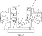
- FIG. 1 shows a fixture (nest) 20 for holding a part 22 ( FIG. 3 ) in position during an operation such as machining.
- FIG. 3 further schematically shows a machine tool 24.
- An example tool 24 is a rotary grinding tool (e.g., having a bit 26 such as an abrasive grinding wheel or a quill).
- the tool 24 may be manipulated/maneuvered via an actuator 28 such as an industrial robot (e.g., a six-axis robot).
- Alternative tools include electro-discharge machining (EDM) tools with associated electrodes/dies.
- EDM electro-discharge machining
- the example part 22 is a gas turbine engine component.
- the example gas turbine engine component is a vane cluster having a plurality of airfoils 900 extending between an inner diameter (ID) platform or shroud 902 and an outer diameter (OD) shroud 904.
- the part consists of an alloy substrate (e.g., Ni superalloy or Ti alloy).
- the substrate may be coated (e.g., with corrosion coatings, thermal and/or environmental barrier coatings, and the like).
- the fixture 20 ( FIG. 2 ) is a complex assembly which may comprise a body 30 and one or more movable engagement/securing members 32 such as clamps for holding the part in place in the fixture.
- Example clamps are hydraulic clamps or pneumatic clamps (e.g., linear hydraulic clamps or linear pneumatic clamps).
- the fixture body 30 ( FIG. 2 ) defines a plurality of contact points with the part. At least some of these contact points are formed by part-contacting elements 34 of respective switches 36.
- the switches are mounted to a main body structure 38 (e.g., a metal frame) of the fixture body.
- a main body structure 38 e.g., a metal frame
- two contact points are on a first axial end face of the platform 902; another two are on a corresponding axial end face of the shroud 904; a fifth is on a first circumferential end face of the platform; a sixth is on the corresponding first circumferential end face of the shroud; and a seventh is on an outer diameter (OD) rim surface of the shroud 904.
- the clamps engage respective internal axial-extending faces of the platform and shroud to draw the part against the first four contact points (formed by part-contacting elements 34).
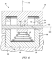
- the example switches 36 each comprise a housing 40 mounted to the main body structure 38 and said part-engaging element 34 mounted to the associated housing 40 for an axial range of motion between a compressed/contracted condition ( FIG. 6 ) and an extended condition ( FIGs. 4 &5).
- the part-engaging element is biased away from the housing toward the extended condition from the compressed condition.
- An example bias is provided by one or more compliant/yielding biasing members such as springs 42.
- the housing 40 has a housing body 41 (e.g., metallic such as a single alloy piece such as a stainless steel) threaded into the main body structure 38.
- the main body structure 38 has an internally-threaded compartment or hole 44 extending from a base surface 46 to an open outer end.
- the housing body 41 itself is generally cylindrically cup-shaped having a base 48 and a sidewall 50 extending from the base 48 to a rim 52.
- the base 48 has an underside 54 and an inboard/interior surface 56.
- the sidewall has an inner diameter (ID) surface 58 and an externally threaded outer diameter (OD) surface 60. In the installed condition, the sidewall external thread is mated to the hole 44 internal thread.
- the sidewall includes a central longitudinal axis 510 shared with the hole and with the example part-contacting element when installed.
- the sidewall includes a pair of diametrically opposed axial (axially elongate) slots 70 ( FIG. 5 ) .
- the example slots are radial through-slots extending between the sidewall ID and OD surfaces but have respective lower ends 72 and upper ends 74 (i.e., not extending to the sidewall rim).
- the example part-contacting element 34 is shown as a cap for the housing.
- the example cap is a cap assembly comprising a cap body 80 (e.g., metallic such as a single alloy piece such as a stainless steel) having a top web 82 and a sidewall 84 extending (depending) from the top web 82 to a lower rim 86.
- a cap body 80 e.g., metallic such as a single alloy piece such as a stainless steel
- the top web 82 has a top (outer) surface 90 and an underside 92.
- the sidewall 84 has an inner diameter (ID) surface 94 and an outer diameter (OD) surface 96.
- the example cap body 80 also has a central shaft 98 depending from the top web underside to a lower end 100 and having an outer diameter (OD) surface 102.
- the cap assembly further includes a pin 120 mounted to the cap body and passing through the housing slots.
- the cooperation between the pin and slots serves as a stop mechanism to provide a stop the extended condition.
- the example pin 120 e.g., a single alloy piece such as a stainless steel
- the example pin 120 has a pair of ends 122 and an outer diameter (OD) surface 124 relative to a pin axis 520 shared with the holes 106 and 108 when installed.
- the pin may have an interference relation with the cap body at one or more of those holes.
- the switch further comprises a pair of electrical contacts 140, 142.
- the example housing electrical contact 140 is on the rim of the housing body.
- the example cap contact 142 is on the underside of the web.
- the contacts e.g., each a single alloy piece such as brass
- adhesive 141, 143 e.g., epoxy which also serves as an electrical insulator.
- Alternative insulators may be pre-formed (e.g., cut from plastic or elastomeric sheet).
- Alternative contacts may be thin laminates with an electrically insulative layer separating a metallic conductor from the associated body.
- the example cap contact 142 consists of or comprises an annulus.
- the example housing contact 140 comprises an annular upper potion 144 on the housing rim, a circular base 145 atop the housing base, and legs 146 joining the base and extending along the housing sidewall.
- Electrodes 150, 152 may extend from the contacts and penetrate the housing body to connect to associated electronics (discussed below). In the basic implementation, these may be copper or other wires soldered to the contacts. The leads may proceed to electrical connectors for ultimate connection with further wiring components.
- FIG. 6 shows the compressed condition.
- the contacts 140, 142 are contacting each other and acting as a stop on further compressive movement of the cap.
- the pin 120 is close to the slot lower ends 72 but clear of them so that the precise position is determined by contact at the contacts 140, 142.
- FIG. 5 shows an extended condition wherein there is a gap between the contacts 140, 142 and wherein the pin 120 contacts the slot upper ends 74 to serve as a stop on further extensive movement. Throughout this range of motion, an upper portion of the housing sidewall is telescoped within the cap sidewall with housing sidewall OD surface in contact with cap sidewall ID surface.
- housing and cap may be selected so that there is sufficient circumferential contact to seal the interior of the switch. This sealing prevents infiltration of particulates (e.g., machining debris) but also liquids such as coolant or cutting fluid which may electrically interfere with operation (e.g., by bridging contacts and causing false closed circuits or by providing an insulative effect and causing false open circuits). To balance sealing with binding, the dimensional tolerances should limit any friction to below what the biasing member 42 can overcome.
- particulates e.g., machining debris
- liquids such as coolant or cutting fluid which may electrically interfere with operation (e.g., by bridging contacts and causing false closed circuits or by providing an insulative effect and causing false open circuits).
- the dimensional tolerances should limit any friction to below what the biasing member 42 can overcome.
- the example switch manufacture process involves manufacturing the housing body by machining from rod stock.
- the cap body may also be machined from rod stock.
- the pin may be cut from rod stock or otherwise machined.
- the slots may be machined (e.g., via end mill or the like).
- the cap holes may be drilled (e.g., via a single drilling plunge).
- the thread may be die cut.
- the contacts may be made via stamping or laser cutting from sheet stock.
- the contacts may be assembled to the housing body and cap body via insertion after pre-application of epoxy. Passageways for the wires may be formed in the housing body such as via drilling.
- the wires may be attached to the contacts via soldering.
- the assembly process may pass the wires through the respective wire holes and seal the holes such as via a silicone or other sealant.
- the biasing member 42 (e.g., spring) may be put in place and held via gravity with the housing body upright.
- the example spring is a frustoconical conical coil spring (e.g., alloy such as stainless steel) so that the spring base fills the base of the housing compartment to center the spring.
- the narrow spring upper/distal end is dimensioned to engage the end of the cap body stem.
- Alternative biasing members include leaf springs, wave springs, and the like and may include plastics instead of metal and may include compression of an elastomer.
- the cap may be put in place and depressed sufficiently to align its holes 106, 108 with the housing body slots 70 whereupon the pin may be pressed through.
- Additional component materials and manufacture techniques and assembly techniques may be otherwise conventional.
- FIG. 7 schematically shows an electrical system 800 coupled to multiple pairs of the wires 150, 152 and to a power source 810 (e.g., battery, external factory power, and the like).
- the system may have display means 802 for displaying switch status.
- a simple example of display means is a light such as an LED light for each switch.
- a simplest configuration directly wires each light to an associated switch via the power source so that the light lights when the switch is closed.
- Alternative electronics may be provided to light the lights when the switch is open.
- Yet alternative display means include flat panel displays where switch state is displayed via icons or the like.
- the part In use, as the part is loaded (by technician hand or handling robot) into the nest and clamped, the part will compress the caps against their bias (e.g., spring load). If properly seated, the respective contact of the switches will establish electrical contact. This causes display of condition state.
- bias e.g., spring load
- first, second, and the like in the following claims is for differentiation within the claim only and does not necessarily indicate relative or absolute importance or temporal order. Similarly, the identification in a claim of one element as “first” (or the like) does not preclude such "first” element from identifying an element that is referred to as “second” (or the like) in another claim or in the description.
Landscapes
- Engineering & Computer Science (AREA)
- Mechanical Engineering (AREA)
- Electrical Discharge Machining, Electrochemical Machining, And Combined Machining (AREA)
- Switch Cases, Indication, And Locking (AREA)
- Arc-Extinguishing Devices That Are Switches (AREA)
Abstract
Description
- The disclosure relates to gas turbine engines. More particularly, the disclosure relates to machining of metallic components (parts or elements) such as blades and vanes.
- Gas turbine engines (used in propulsion and power applications and broadly inclusive of turbojets, turboprops, turbofans, turboshafts, industrial gas turbines, and the like) typically include precision-machined cast parts.
- For example, with blades and vanes the contours of the airfoil are roughly cast and then precision ground.
- In order to grind features on the airfoil, the part is located/registered in a grinding fixture to prevent movement during machining. The grinding fixture has at least six datum features for the part to be fully constrained during a high-force grind operation. The part is clamped to the fixture for machining.
- Part misloading to the fixture is a frequent problem for blade/vane programs. In one example, proper part loading relies on an operator checking with a shim to ensure the part is fully loaded on the fixture. Often, the operator misloads the part and doesn't verify all datum locations for proper part seating.
- Also, during the grind operation the forces from the grinding tool (e.g., grinding wheel) on the part may lift the part off of the fixture causing the ground part to be out of spec. This nonconformity may only substantially later be detected (e.g., caught in an inspection immediately post-grinding or yet later). Depending on circumstances, the inspection may not reveal the cause of the nonconformity. This may be significant if multiple grinding steps are performed in successive fixtures. For example, the part may be inspected at an in-process coordinate measuring machine (CMM) after a few operations so as to prevent escapes. Such inspection doesn't prevent nonconformities or scrap. Thus, the misloading without operator knowledge of root cause results in unknown scrap quantities or quality nonconformance (QN) submission.
- One aspect of the present invention involves a switch having a housing having a housing body comprising a base and a sidewall. The sidewall has an axis and extends from the base to a rim and has: an outer diameter surface having an external thread; and a pair of axial slots. The switch has a cap having a cap body having: a top web; and a sidewall extending from the top web to a rim and having a pair of holes. The cap has a shaft passing through the pair of axial slots and pair of holes. The cap is biased axially away from the housing along an axial range of motion from a compressed condition to an extended condition. A cap electrical contact and a housing electrical contact are respectively on the cap and the housing and have an electrically closed condition at the compressed condition.
- Optionally, the housing body comprises stainless steel.
- Optionally, the cap body comprises stainless steel.
- Optionally, the housing electrical contact is mounted to the housing body sidewall rim and the cap electrical contact is mounted to an underside of the cap body top web. Respective electrical leads for the housing electrical contact and cap electrical contact pass through respective holes in the housing body.
- Optionally, a spring biases the cap axially away from the housing along the axial range of motion from the compressed condition to the extended condition.
- Optionally, the spring is a frustoconical coil spring.
- Optionally, the cap further comprises a stem having a transverse hole, the shaft passes through the transverse hole, and the spring bears against the stem.
- Optionally, a machining fixture for holding a part to be machined. The machining fixture including a plurality of the switches and further comprising a body having a plurality of holes into which the plurality of switches are respectively threaded.
- Optionally, the machining fixture of further comprises one or more clamps for holding the part in an installed condition compressing the plurality of switches.
- Optionally, the one or more clamps are hydraulic clamps.
- Optionally, the machining fixture further comprises means for displaying respective states of the plurality of switches.
- Optionally, a method for using the machining fixture comprises: installing a part to the machining fixture, the installing depressing the plurality of switches to their respective compressed conditions; and machining the installed part.
- Optionally, the method of further comprises displaying respective states of the plurality of switches.
- Optionally, the machining is responsive to displayed closed state of all switches of the plurality of switches.
- A further aspect of the present invention involves, a fixture for processing a part. The fixture comprises: a body having a plurality of threaded holes. A plurality of switches have: a body mounted in a respective associated hole of the plurality of threaded holes; and a part-engaging member for contacting the part in an installed condition of the part and mounted to the body for axial movement between a compressed condition and an extended condition. The part-engaging member is biased from the compressed condition toward the extended condition. Each switch has a body electrical contact and a part-engaging member electrical contact for contacting the body electrical in the compressed condition. At least one clamp holds the part in the installed condition.
- Optionally, the at least one clamp comprises a pair of hydraulic clamps.
- Optionally, the fixture further comprises means for displaying respective states of the plurality of switches.
- Optionally, a method for using the fixture comprises: installing a part to the machining fixture, the installing depressing the plurality of switches to their respective compressed conditions; and machining the installed part.
- Optionally, the method of further comprises displaying respective states of the plurality of switches.
- Optionally, the machining is responsive to displayed closed state of all switches of the plurality of switches.
- The details of one or more embodiments are set forth in the accompanying drawings and the description below. Other features, objects, and advantages will be apparent from the description and drawings, and from the claims.
-
-
FIG. 1 is a first view of a machining fixture. -
FIG. 2 is a second view of the machining fixture. -
FIG. 3 is a view of the machining fixture holding a part shown in broken lines. -
FIG. 4 is a first central longitudinal sectional view of a positioning switch of the fixture in an extended condition. -
FIG. 5 is a second central longitudinal sectional view of the positioning switch orthogonal toFIG. 4 . -
FIG. 6 is a central longitudinal sectional view of the switch ofFIG. 5 in a compressed condition. -
FIG. 7 is a schematic view of an electrical system including the switches. - Like reference numbers and designations in the various drawings indicate like elements.
-
FIG. 1 shows a fixture (nest) 20 for holding a part 22 (FIG. 3 ) in position during an operation such as machining.FIG. 3 further schematically shows amachine tool 24. Anexample tool 24 is a rotary grinding tool (e.g., having abit 26 such as an abrasive grinding wheel or a quill). Thetool 24 may be manipulated/maneuvered via anactuator 28 such as an industrial robot (e.g., a six-axis robot). Alternative tools include electro-discharge machining (EDM) tools with associated electrodes/dies. - The
example part 22 is a gas turbine engine component. The example gas turbine engine component is a vane cluster having a plurality ofairfoils 900 extending between an inner diameter (ID) platform orshroud 902 and an outer diameter (OD)shroud 904. For a typical original manufacture machining process, the part consists of an alloy substrate (e.g., Ni superalloy or Ti alloy). In alternative repair or other processes, the substrate may be coated (e.g., with corrosion coatings, thermal and/or environmental barrier coatings, and the like). - The fixture 20 (
FIG. 2 ) is a complex assembly which may comprise abody 30 and one or more movable engagement/securingmembers 32 such as clamps for holding the part in place in the fixture. Example clamps are hydraulic clamps or pneumatic clamps (e.g., linear hydraulic clamps or linear pneumatic clamps). - The fixture body 30 (
FIG. 2 ) defines a plurality of contact points with the part. At least some of these contact points are formed by part-contactingelements 34 of respective switches 36. The switches are mounted to a main body structure 38 (e.g., a metal frame) of the fixture body. In the example: two contact points are on a first axial end face of theplatform 902; another two are on a corresponding axial end face of theshroud 904; a fifth is on a first circumferential end face of the platform; a sixth is on the corresponding first circumferential end face of the shroud; and a seventh is on an outer diameter (OD) rim surface of theshroud 904. - The clamps engage respective internal axial-extending faces of the platform and shroud to draw the part against the first four contact points (formed by part-contacting elements 34).
- The example switches 36 (
FIG. 4 ) each comprise ahousing 40 mounted to themain body structure 38 and said part-engagingelement 34 mounted to the associatedhousing 40 for an axial range of motion between a compressed/contracted condition (FIG. 6 ) and an extended condition (FIGs. 4 &5). The part-engaging element is biased away from the housing toward the extended condition from the compressed condition. An example bias is provided by one or more compliant/yielding biasing members such as springs 42. - In the example configuration, the
housing 40 has a housing body 41 (e.g., metallic such as a single alloy piece such as a stainless steel) threaded into themain body structure 38. To this end, for eachswitch 36, themain body structure 38 has an internally-threaded compartment orhole 44 extending from abase surface 46 to an open outer end. - The
housing body 41 itself is generally cylindrically cup-shaped having a base 48 and asidewall 50 extending from the base 48 to arim 52. Thebase 48 has anunderside 54 and an inboard/interior surface 56. The sidewall has an inner diameter (ID)surface 58 and an externally threaded outer diameter (OD)surface 60. In the installed condition, the sidewall external thread is mated to thehole 44 internal thread. As is discussed further below, the sidewall includes a centrallongitudinal axis 510 shared with the hole and with the example part-contacting element when installed. The sidewall includes a pair of diametrically opposed axial (axially elongate) slots 70 (FIG. 5 ) . The example slots are radial through-slots extending between the sidewall ID and OD surfaces but have respective lower ends 72 and upper ends 74 (i.e., not extending to the sidewall rim). - The example part-contacting
element 34 is shown as a cap for the housing. The example cap is a cap assembly comprising a cap body 80 (e.g., metallic such as a single alloy piece such as a stainless steel) having atop web 82 and asidewall 84 extending (depending) from thetop web 82 to alower rim 86. - The
top web 82 has a top (outer)surface 90 and anunderside 92. Thesidewall 84 has an inner diameter (ID)surface 94 and an outer diameter (OD)surface 96. - The
example cap body 80 also has acentral shaft 98 depending from the top web underside to alower end 100 and having an outer diameter (OD)surface 102. - The cap assembly further includes a
pin 120 mounted to the cap body and passing through the housing slots. The cooperation between the pin and slots serves as a stop mechanism to provide a stop the extended condition. The example pin 120 (e.g., a single alloy piece such as a stainless steel) passes through two diametricallyopposite holes 106 in thecap body sidewall 84 and ahole 108 in the cap stem. - The
example pin 120 has a pair ofends 122 and an outer diameter (OD)surface 124 relative to apin axis 520 shared with theholes - The switch further comprises a pair of
electrical contacts electrical contact 140 is on the rim of the housing body. Theexample cap contact 142 is on the underside of the web. The contacts (e.g., each a single alloy piece such as brass) may be secured in place such as viaadhesive 141, 143 (e.g., epoxy which also serves as an electrical insulator). Alternative insulators may be pre-formed (e.g., cut from plastic or elastomeric sheet). Alternative contacts may be thin laminates with an electrically insulative layer separating a metallic conductor from the associated body. - The
example cap contact 142 consists of or comprises an annulus. Theexample housing contact 140 comprises an annularupper potion 144 on the housing rim, acircular base 145 atop the housing base, andlegs 146 joining the base and extending along the housing sidewall. - Electrical conductors (leads) 150, 152 (e.g., wires) may extend from the contacts and penetrate the housing body to connect to associated electronics (discussed below). In the basic implementation, these may be copper or other wires soldered to the contacts. The leads may proceed to electrical connectors for ultimate connection with further wiring components.
-
FIG. 6 shows the compressed condition. In this condition, thecontacts pin 120 is close to the slot lower ends 72 but clear of them so that the precise position is determined by contact at thecontacts FIG. 5 shows an extended condition wherein there is a gap between thecontacts pin 120 contacts the slot upper ends 74 to serve as a stop on further extensive movement. Throughout this range of motion, an upper portion of the housing sidewall is telescoped within the cap sidewall with housing sidewall OD surface in contact with cap sidewall ID surface. - The dimensional tolerances of housing and cap may be selected so that there is sufficient circumferential contact to seal the interior of the switch. This sealing prevents infiltration of particulates (e.g., machining debris) but also liquids such as coolant or cutting fluid which may electrically interfere with operation (e.g., by bridging contacts and causing false closed circuits or by providing an insulative effect and causing false open circuits). To balance sealing with binding, the dimensional tolerances should limit any friction to below what the biasing
member 42 can overcome. - The example switch manufacture process involves manufacturing the housing body by machining from rod stock. The cap body may also be machined from rod stock. The pin may be cut from rod stock or otherwise machined. The slots may be machined (e.g., via end mill or the like). Similarly, the cap holes may be drilled (e.g., via a single drilling plunge). The thread may be die cut.
- The contacts may be made via stamping or laser cutting from sheet stock. The contacts may be assembled to the housing body and cap body via insertion after pre-application of epoxy. Passageways for the wires may be formed in the housing body such as via drilling.
- The wires may be attached to the contacts via soldering. The assembly process may pass the wires through the respective wire holes and seal the holes such as via a silicone or other sealant.
- In final assembly, the biasing member 42 (e.g., spring) may be put in place and held via gravity with the housing body upright. The example spring is a frustoconical conical coil spring (e.g., alloy such as stainless steel) so that the spring base fills the base of the housing compartment to center the spring. The narrow spring upper/distal end is dimensioned to engage the end of the cap body stem. Alternative biasing members include leaf springs, wave springs, and the like and may include plastics instead of metal and may include compression of an elastomer. The cap may be put in place and depressed sufficiently to align its
holes housing body slots 70 whereupon the pin may be pressed through. - Additional component materials and manufacture techniques and assembly techniques may be otherwise conventional.
-
FIG. 7 schematically shows anelectrical system 800 coupled to multiple pairs of thewires - In use, as the part is loaded (by technician hand or handling robot) into the nest and clamped, the part will compress the caps against their bias (e.g., spring load). If properly seated, the respective contact of the switches will establish electrical contact. This causes display of condition state.
- The use of "first", "second", and the like in the following claims is for differentiation within the claim only and does not necessarily indicate relative or absolute importance or temporal order. Similarly, the identification in a claim of one element as "first" (or the like) does not preclude such "first" element from identifying an element that is referred to as "second" (or the like) in another claim or in the description.
- One or more embodiments have been described. Nevertheless, it will be understood that various modifications may be made. For example, when applied to an existing baseline part or fixture configuration, details of such baseline may influence details of particular implementations. Accordingly, other embodiments are within the scope of the following claims.
Claims (14)
- A switch (36) comprising:a housing (40) having a housing body (41) comprising:a base (48); anda sidewall (50) having an axis (510) and extending from the base (48) to a rim (52) and having:an outer diameter surface (60) having an external thread; anda pair of axial slots (70);a cap (34) biased axially away from the housing (40) along an axial range of motion from a compressed condition to an extended condition, the cap (34) having:a cap body (80) having:a top web (82); anda sidewall (84) extending from the top web (82) to a rim (86) and having:
a pair of holes (106); anda shaft (120) passing through the pair of axial slots (70) and pair of holes (106); anda cap electrical contact (142) and a housing electrical contact (140) respectively on the cap (34) and the housing (40) and having an electrically closed condition at the compressed condition. - The switch (36) of claim 1 wherein:
the housing body (41) comprises stainless steel. - The switch (36) of claim 1 or 2 wherein:
the cap body (80) comprises stainless steel. - The switch (36) of any preceding claim wherein:the housing electrical contact (140) is mounted to the housing body sidewall rim (52);the cap electrical contact (142) is mounted to an underside of the cap body top web (82); andrespective electrical leads (150, 152) for the housing electrical contact (140) and cap electrical contact (142) pass through respective holes in the housing body (41).
- The switch (36) of any preceding claim wherein:
a spring (42) biases the cap (34) axially away from the housing (40) along the axial range of motion from the compressed condition to the extended condition. - The switch (36) of claim 5 wherein:
the spring (42) is a frustoconical coil spring. - The switch (36) of claim 5 or 6 wherein:the cap (34) further comprises a stem (98) having a transverse hole (108);the shaft (120) passes through the transverse hole (108); andthe spring (42) bears against the stem (98).
- A machining fixture (20) for holding a part (22) to be machined, the machining fixture (20) including a plurality of switches (36) of any preceding claim and further comprising:
a body (30) having a plurality of holes (44) into which the plurality of switches (36) are respectively threaded. - The machining fixture (20) of claim 8 further comprising:
one or more clamps (32) for holding the part (22) in an installed condition compressing the plurality of switches (36) . - The machining fixture (20) of claim 9 wherein:
the one or more clamps (32) are hydraulic clamps. - The machining fixture (20) of any of claims 8 to 10 further comprising:
means (802) for displaying respective states of the plurality of switches (36). - A method for using the machining fixture (20) of any of claims 8 to 11, the method comprising:installing a part (22) to the machining fixture (20), the installing depressing the plurality of switches (36) to their respective compressed conditions; andmachining the installed part (22).
- The method of claim 12 further comprising:
displaying respective states of the plurality of switches (36) . - The method of claim 12 or 13 wherein:
the machining is responsive to displayed closed state of all switches (36) of the plurality of switches (36).
Applications Claiming Priority (2)
| Application Number | Priority Date | Filing Date | Title |
|---|---|---|---|
| US202163166491P | 2021-03-26 | 2021-03-26 | |
| EP21193134.0A EP4063070B1 (en) | 2021-03-26 | 2021-08-25 | Machining fixture and method of using the same |
Related Parent Applications (1)
| Application Number | Title | Priority Date | Filing Date |
|---|---|---|---|
| EP21193134.0A Division EP4063070B1 (en) | 2021-03-26 | 2021-08-25 | Machining fixture and method of using the same |
Publications (3)
| Publication Number | Publication Date |
|---|---|
| EP4327977A2 true EP4327977A2 (en) | 2024-02-28 |
| EP4327977A3 EP4327977A3 (en) | 2024-05-01 |
| EP4327977B1 EP4327977B1 (en) | 2026-03-25 |
Family
ID=77518939
Family Applications (2)
| Application Number | Title | Priority Date | Filing Date |
|---|---|---|---|
| EP24151040.3A Active EP4327977B1 (en) | 2021-03-26 | 2021-08-25 | Machining fixture positioning switch |
| EP21193134.0A Active EP4063070B1 (en) | 2021-03-26 | 2021-08-25 | Machining fixture and method of using the same |
Family Applications After (1)
| Application Number | Title | Priority Date | Filing Date |
|---|---|---|---|
| EP21193134.0A Active EP4063070B1 (en) | 2021-03-26 | 2021-08-25 | Machining fixture and method of using the same |
Country Status (2)
| Country | Link |
|---|---|
| US (1) | US12226869B2 (en) |
| EP (2) | EP4327977B1 (en) |
Family Cites Families (13)
| Publication number | Priority date | Publication date | Assignee | Title |
|---|---|---|---|---|
| GB1396129A (en) * | 1972-07-04 | 1975-06-04 | Flight Refueling Ltd | Electrical switches |
| US3862389A (en) * | 1973-03-26 | 1975-01-21 | Charles Thomas Lowe | Positive stop electrical switch |
| US4694130A (en) * | 1986-08-29 | 1987-09-15 | General Motors Corporation | Illuminated pushbutton switch with unitary spring and contact |
| EP0774320A1 (en) | 1995-11-20 | 1997-05-21 | Elpatronic Ag | Method for positioning and aligning workpieces |
| US7498538B1 (en) * | 2007-07-20 | 2009-03-03 | Judco Manufacturing, Inc. | Sliding contact switch |
| GB2458738A (en) * | 2008-04-04 | 2009-10-07 | Heller Machine Tools Ltd | Holding device for non planar work piece |
| DE102009032703A1 (en) * | 2009-07-09 | 2011-01-13 | Mtu Aero Engines Gmbh | Device and method for arranging a component on a component carrier |
| KR20120003022U (en) * | 2010-10-25 | 2012-05-03 | 서울메트로 | Push device of door interlock switch for railway vehicle |
| WO2015162402A2 (en) | 2014-04-24 | 2015-10-29 | Bae Systems Plc | Machining fixture production |
| EP3166123B1 (en) * | 2015-11-09 | 2018-05-02 | Microprécision Electronics Holding SA | Electrical switch |
| US10227874B2 (en) | 2016-09-27 | 2019-03-12 | General Electric Company | Tooling fixture assembly for processing a component of a gas turbine engine |
| DE102017113416B3 (en) * | 2017-06-19 | 2018-06-07 | Fixtest Prüfmittelbau GmbH | MICROSWITCH AND TEST SYSTEM |
| US10312029B2 (en) * | 2017-08-30 | 2019-06-04 | Scs Elevator Products Inc. | Illuminated vandal-resistant pushbutton switch |
-
2021
- 2021-08-25 EP EP24151040.3A patent/EP4327977B1/en active Active
- 2021-08-25 EP EP21193134.0A patent/EP4063070B1/en active Active
-
2022
- 2022-03-01 US US17/683,545 patent/US12226869B2/en active Active
Also Published As
| Publication number | Publication date |
|---|---|
| EP4327977A3 (en) | 2024-05-01 |
| EP4063070B1 (en) | 2024-01-10 |
| US12226869B2 (en) | 2025-02-18 |
| US20220305600A1 (en) | 2022-09-29 |
| EP4327977B1 (en) | 2026-03-25 |
| EP4063070A1 (en) | 2022-09-28 |
Similar Documents
| Publication | Publication Date | Title |
|---|---|---|
| JP4572403B2 (en) | Method and apparatus for aligning parts for inspection | |
| CN101829996A (en) | Mechanical interface and manipulator applying same | |
| SE1550042A1 (en) | Device for detachable and repeatable positioning of two objects in relation to each other | |
| US20040255702A1 (en) | Methods for inspecting components | |
| CN209350069U (en) | A kind of high-precision hydraulic centering center rest | |
| US12226869B2 (en) | Machining fixture positioning switch | |
| CN110560746A (en) | inclined hole drilling device and application method thereof | |
| US20070056180A1 (en) | Methods and apparatus for manufacturing components | |
| KR20090082206A (en) | Clamping method for workpieces used to manufacture compressors or turbine wheels | |
| CN114211199B (en) | A combined processing method for two-half thin-walled parts (static vanes) | |
| JP2019526451A (en) | Molds and devices for positioning joining elements or for clinch joining | |
| JP2019526451A5 (en) | ||
| CN107063079A (en) | Measure the relative Concentricity tolerance in the restricted clearance between two ring elements | |
| CN108827105B (en) | Engine body thrust block width dimension checking fixture | |
| CN114700537A (en) | Positioning numerical milling fixture and numerical milling machining method for metal sealing ring of power turbine casing | |
| CN205066738U (en) | Casing hangs down straightness and detects instrument | |
| EP3971515A1 (en) | Eddie-bolt inspection tool | |
| CN220837980U (en) | Numerical control lathe jack catch pressure detection tool | |
| CN119178378B (en) | Machining detection method and device for forged flange part with steel ring pressed | |
| CN121624885B (en) | Machining device and machining method for turbine product for aero-engine | |
| CN205733991U (en) | A kind of Small Cylindrical body punching parts quick clamping mechanism | |
| CN119388468B (en) | Multilayer terminal quick-change system of explosion-proof humanoid robot, terminal executor and humanoid robot | |
| CN216523584U (en) | Measure internal diameter tool of auto parts machining product size | |
| JPH05192886A (en) | Tool holding device | |
| CN222703982U (en) | Groove diameter gauge |
Legal Events
| Date | Code | Title | Description |
|---|---|---|---|
| PUAI | Public reference made under article 153(3) epc to a published international application that has entered the european phase |
Free format text: ORIGINAL CODE: 0009012 |
|
| STAA | Information on the status of an ep patent application or granted ep patent |
Free format text: STATUS: THE APPLICATION HAS BEEN PUBLISHED |
|
| AC | Divisional application: reference to earlier application |
Ref document number: 4063070 Country of ref document: EP Kind code of ref document: P |
|
| AK | Designated contracting states |
Kind code of ref document: A2 Designated state(s): AL AT BE BG CH CY CZ DE DK EE ES FI FR GB GR HR HU IE IS IT LI LT LU LV MC MK MT NL NO PL PT RO RS SE SI SK SM TR |
|
| REG | Reference to a national code |
Ref country code: DE Ref legal event code: R079 Free format text: PREVIOUS MAIN CLASS: B23Q0003060000 Ipc: B24B0047220000 Ref country code: DE Ref legal event code: R079 Ref document number: 602021050932 Country of ref document: DE Free format text: PREVIOUS MAIN CLASS: B23Q0003060000 Ipc: B24B0047220000 |
|
| PUAL | Search report despatched |
Free format text: ORIGINAL CODE: 0009013 |
|
| AK | Designated contracting states |
Kind code of ref document: A3 Designated state(s): AL AT BE BG CH CY CZ DE DK EE ES FI FR GB GR HR HU IE IS IT LI LT LU LV MC MK MT NL NO PL PT RO RS SE SI SK SM TR |
|
| RIC1 | Information provided on ipc code assigned before grant |
Ipc: H01H 3/16 20060101ALN20240328BHEP Ipc: B23Q 3/06 20060101ALI20240328BHEP Ipc: H01H 13/18 20060101ALI20240328BHEP Ipc: B24B 49/10 20060101ALI20240328BHEP Ipc: B24B 19/14 20060101ALI20240328BHEP Ipc: B24B 47/22 20060101AFI20240328BHEP |
|
| STAA | Information on the status of an ep patent application or granted ep patent |
Free format text: STATUS: REQUEST FOR EXAMINATION WAS MADE |
|
| 17P | Request for examination filed |
Effective date: 20241101 |
|
| RBV | Designated contracting states (corrected) |
Designated state(s): AL AT BE BG CH CY CZ DE DK EE ES FI FR GB GR HR HU IE IS IT LI LT LU LV MC MK MT NL NO PL PT RO RS SE SI SK SM TR |
|
| GRAP | Despatch of communication of intention to grant a patent |
Free format text: ORIGINAL CODE: EPIDOSNIGR1 |
|
| STAA | Information on the status of an ep patent application or granted ep patent |
Free format text: STATUS: GRANT OF PATENT IS INTENDED |
|
| RIC1 | Information provided on ipc code assigned before grant |
Ipc: B24B 47/22 20060101AFI20250918BHEP Ipc: B24B 19/14 20060101ALI20250918BHEP Ipc: B24B 49/10 20060101ALI20250918BHEP Ipc: H01H 13/18 20060101ALI20250918BHEP Ipc: B23Q 3/06 20060101ALI20250918BHEP Ipc: H01H 3/16 20060101ALN20250918BHEP |
|
| INTG | Intention to grant announced |
Effective date: 20251015 |
|
| GRAS | Grant fee paid |
Free format text: ORIGINAL CODE: EPIDOSNIGR3 |
|
| GRAA | (expected) grant |
Free format text: ORIGINAL CODE: 0009210 |
|
| STAA | Information on the status of an ep patent application or granted ep patent |
Free format text: STATUS: THE PATENT HAS BEEN GRANTED |
|
| AC | Divisional application: reference to earlier application |
Ref document number: 4063070 Country of ref document: EP Kind code of ref document: P |
|
| AK | Designated contracting states |
Kind code of ref document: B1 Designated state(s): AL AT BE BG CH CY CZ DE DK EE ES FI FR GB GR HR HU IE IS IT LI LT LU LV MC MK MT NL NO PL PT RO RS SE SI SK SM TR |
|
| REG | Reference to a national code |
Ref country code: CH Ref legal event code: F10 Free format text: ST27 STATUS EVENT CODE: U-0-0-F10-F00 (AS PROVIDED BY THE NATIONAL OFFICE) Effective date: 20260325 Ref country code: GB Ref legal event code: FG4D |
|
| REG | Reference to a national code |
Ref country code: DE Ref legal event code: R096 Ref document number: 602021050932 Country of ref document: DE |
|
| REG | Reference to a national code |
Ref country code: IE Ref legal event code: FG4D |