EP4327956A1 - Wire drawing die - Google Patents
Wire drawing die Download PDFInfo
- Publication number
- EP4327956A1 EP4327956A1 EP22807399.5A EP22807399A EP4327956A1 EP 4327956 A1 EP4327956 A1 EP 4327956A1 EP 22807399 A EP22807399 A EP 22807399A EP 4327956 A1 EP4327956 A1 EP 4327956A1
- Authority
- EP
- European Patent Office
- Prior art keywords
- wire drawing
- die
- heat radiation
- wire
- side end
- Prior art date
- Legal status (The legal status is an assumption and is not a legal conclusion. Google has not performed a legal analysis and makes no representation as to the accuracy of the status listed.)
- Granted
Links
Images



Classifications
-
- B—PERFORMING OPERATIONS; TRANSPORTING
- B21—MECHANICAL METAL-WORKING WITHOUT ESSENTIALLY REMOVING MATERIAL; PUNCHING METAL
- B21C—MANUFACTURE OF METAL SHEETS, WIRE, RODS, TUBES, PROFILES OR LIKE SEMI-MANUFACTURED PRODUCTS OTHERWISE THAN BY ROLLING; AUXILIARY OPERATIONS USED IN CONNECTION WITH METAL-WORKING WITHOUT ESSENTIALLY REMOVING MATERIAL
- B21C3/00—Profiling tools for metal drawing; Combinations of dies and mandrels for metal drawing
- B21C3/02—Dies; Selection of material therefor; Cleaning thereof
- B21C3/025—Dies; Selection of material therefor; Cleaning thereof comprising diamond parts
Definitions
- the present disclosure relates to a wire drawing die.
- the present application claims priority based on Japanese Patent Application No. 2021-080723 filed on May 12, 2021 .
- the entire description of the Japanese Patent Application are incorporated herein by reference.
- a wire drawing die is disclosed, for example, in Japanese Patent Laying-Open No. 9-108726 (PTL 1).
- a wire drawing die includes: a wear-resistant member provided with a die hole for performing a wire drawing process onto a wire material; and a die case that supports the wear-resistant member, wherein the wear-resistant member has a thermal conductivity higher than a thermal conductivity of the die case, and the wear-resistant member has an upstream-side end surface and a downstream-side end surface in a wire drawing direction, the die hole is provided between the upstream-side end surface and the downstream-side end surface, and the downstream-side end surface is exposed from the die case.
- a wire drawing die includes: a wear-resistant member provided with a die hole for performing a wire drawing process onto a wire material; and a die case that supports the wear-resistant member, wherein the wear-resistant member has a thermal conductivity higher than a thermal conductivity of the die case, and the wear-resistant member has an upstream-side end surface and a downstream-side end surface in a wire drawing direction, the die hole is provided between the upstream-side end surface and the downstream-side end surface, and the downstream-side end surface is exposed from the die case.
- the wire drawing die further includes a cover provided with a through hole through which the wire material is able to pass, wherein the cover has a heat radiation member that is in contact with the wear-resistant member and that is provided with the through hole, and a supporting member that supports the heat radiation member, and the heat radiation member has a thermal conductivity higher than a thermal conductivity of the supporting member.
- the heat radiation member includes at least one selected from a group consisting of diamond, CBN, and a composite material including diamond or CBN.
- the heat radiation member can radiate heat efficiently.
- the supporting member is one of: at least one simple substance selected from a group consisting of copper, silver, tungsten and molybdenum, or an alloy including the simple substance; or a simple substance of a ceramic material or a composite substance of the ceramic material and a metal.
- the strength of the supporting member is high.
- the heat radiation member and the supporting member are joined to each other by a brazing material or screwing.
- the heat radiation member and the supporting member are firmly joined to each other by the brazing material or the screwing. As a result, the heat radiation member can be prevented from falling from the supporting member.
- a plating layer is provided on a joining surface between the heat radiation member and the supporting member.
- the heat radiation member and the supporting member are firmly joined to each other at the joining surface between the heat radiation member and the supporting member.
- Heat generated at a processing portion of a general wire drawing die is transferred in the order of a blank (diamond), a mount material (NiCu or Cu-based alloy), a SUS case, and outside (lubricant or the like) and is accordingly radiated.
- the mount material has a thermal conductivity of several hundred W, and therefore has a heat radiation property inferior to that of diamond, which is the material of the blank and has a thermal conductivity of 1500 W, with the result that the temperature of the mount material is increased and also heat is less likely to be radiated from the blank portion.
- the SUS case is provided around the mount material and the material thereof has a thermal conductivity of ten several W and therefore has a low heat radiation performance, with the result that the temperature of the mount material is likely to be increased also in view of this point.
- a diameter D of a bearing portion of the die hole is 10 ⁇ m or more and 1.0 mm or less. In this range, the life of the wire drawing die is expected to be the longest.
- a length L of a bearing portion of the die hole is 20%D or more and 100%D or less. In this range, the life of the wire drawing die is expected to be the longest. 20%D indicates 20% of D.
- Fig. 1 is a plan view of a wire drawing die 100 according to an embodiment.
- wire drawing die 100 has: a die case 110; and a blank 120 serving as a wear-resistant member supported by die case 110.
- a die hole 103 is provided in blank 120 that is located at the center.
- die hole 103 has a circular shape, but die hole 103 may have a quadrangular shape.
- Blank 120 is composed of a material having high wear resistance such as diamond, CBN, or a cemented carbide, for example.
- a mount material such as a Ni alloy or a Cu alloy is provided between blank 120 and die case 110.
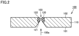
- Fig. 2 is a cross sectional view of wire drawing die 100 along a line II-II in Fig. 1 .
- blank 120 is embedded in a central portion of die case 110 having a cross section with a quadrangular shape.
- a wire material is inserted into die hole 103 provided in blank 120, in a direction indicated by an arrow 100a.
- the wire material is brought into contact with the inner surface of die hole 103 and is processed by blank 120 to have a reduced diameter.
- Blank 120 has: an upstream-side end surface 121 located on the upstream side in the wire drawing direction indicated by the arrow; and a downstream-side end surface 122 located on the downstream side in the wire drawing direction.
- Die case 110 has: a first surface 101 located on the upstream side in the direction of insertion of the wire material as indicated by arrow 100a; and a second surface 102 opposite to first surface 101.
- Blank 120 is positioned between first surface 101 and second surface 102.
- Fig. 3 is a cross sectional view showing an inner surface shape of die hole 103 provided in blank 120 in Fig. 2 in detail.
- die hole 103 has a bell portion 1a, an approach portion 1b, a reduction portion 1c, a bearing portion 1d, a back relief portion 1e, and an exit portion 1f in this order from the upstream side.
- the diameter of die hole 103 is the smallest in bearing portion 1d.
- the wire material is plastically processed by bearing portion 1d.
- the inner diameter of bearing portion 1d is determined based on the diameter of the wire material having been processed.
- Wire drawing die 100 includes: blank 120 serving as the wear-resistant member and provided with die hole 103 for performing the wire drawing process onto the wire material; and die case 110 that supports blank 120.
- Blank 120 has a thermal conductivity higher than that of die case 110.
- Blank 120 has upstream-side end surface 121 and downstream-side end surface 122 in the wire drawing direction, die hole 103 is provided between upstream-side end surface 121 and downstream-side end surface 122, and downstream-side end surface 122 is exposed from die case 110.
- Fig. 4 is a plan view of a cover 200 attached to wire drawing die 100 according to the embodiment.
- Wire drawing die 100 further includes cover 200 provided with a through hole 203 through which the wire material can pass.
- Cover 200 has a heat radiation member 220 that is in contact with blank 120 and that is provided with through hole 203 and a supporting member 210 that supports heat radiation member 220, and heat radiation member 220 has a thermal conductivity higher than that of supporting member 210.
- Heat radiation member 220 includes at least one selected from a group consisting of diamond, CBN, and a composite material including diamond or CBN.
- Supporting member 210 is composed of, for example, one of: at least one simple substance selected from a group consisting of copper, silver, tungsten and molybdenum, or an alloy including the simple substance; or a simple substance of a ceramic material or a composite substance of the ceramic material and a metal.
- Fig. 5 is a cross sectional view of cover 200 along a line V-V in Fig. 4 .
- cover 200 has a first surface 201 located on the upstream side in the wire drawing direction, and a second surface 202 located on the downstream side in the wire drawing direction.
- Heat radiation member 220 is exposed from first surface 201. Through hole 203 of heat radiation member 220 communicates with through hole 204 of supporting member 210.
- Heat radiation member 220 and supporting member 210 may be joined to each other by a brazing material or screwing.
- a plating layer may be provided on a joining surface between heat radiation member 220 and supporting member 210. In this case, joining strength between heat radiation member 220 and supporting member 210 becomes large.
- Fig. 6 is a cross sectional view showing wire drawing die 100 to which cover 200 is attached and a wire drawing method using wire drawing die 100. As shown in Fig. 6 , first surface 201 of cover 200 is attached to second surface 102 of wire drawing die 100. The center of die hole 103 coincides with the center of each of through holes 203 and 204.
- a wire material 1 flows in the direction indicated by arrow 100a.
- wire material 1 is brought into contact with bearing portion 1d and is accordingly processed to have a reduced diameter.
- Fig. 7 is a cross sectional view showing a thermal diffusion path in wire drawing die 100 to which cover 200 is attached. As shown in Fig. 7 , heat is generated by the contact between bearing portion 1d and wire material 1. This heat is transferred from blank 120 to heat radiation member 220 as indicated by arrows 10. Thus, heat can be suppressed from being accumulated in blank 120.
- Heat radiation member 220 serving as a first member that has a plate shape and that is composed of a material having a high thermal conductivity is provided below the diamond serving as blank 120 and in contact with blank 120.
- Supporting member 210 serving as a second member having a high thermal conductivity is provided below and around heat radiation member 220 and in contact with heat radiation member 220.
- Die case 110 serving as a third member having a high thermal conductivity is provided above supporting member 210. Blank 120 and heat radiation member 220 are sandwiched and surrounded by die case 110 and supporting member 210.
- the thermal conductivity is improved by using diamond for the first member and using a material such as CuW for each of the second member and the third member.
- heat can be radiated to the outside via blank 120, diamond (heat radiation member 220), and CuW (supporting member 210).
- supporting member 210 serves as a heat sink. As a result, heat can be radiated quickly.
- each of supporting member 210 and die case 110 located around heat radiation member 220 and blank 120 heat radiation to the outside is also excellent.
- Each of the first to third members is reusable and is therefore excellent in terms of cost.
- Diamond is a material having the most excellent thermal conductivity.
- heat radiation member 220 heat sink
- heat generated during wire drawing can be quickly radiated to the outside.
- CuW for supporting member 210 that supports heat radiation member 220, the heat radiation property is further improved.
- blank 120 and heat radiation member 220 are brought into contact with each other in the embodiment, blank 120 may be brought into contact with a coolant without providing cover 200 and heat radiation member 220.
- cover 200 is attachable to and detachable from wire drawing die 100 in the embodiment, cover 200 may be fixed to wire drawing die 100.
- dies having the following specifications were prepared and evaluated.
- the length of bearing portion 1d in the axial direction was found in the following manner: a region having 1.022 D or less with respect to minimum diameter D of bearing portion 1d was defined as bearing portion 1d and the length thereof was found.
- Table 1 Sample Name Evaluation Items A. Heat Sink Die B. Ordinary Die Figs. 1 to 7 Fig. 8 Initial After Wire Drawing (30km) Initial After Wire Drawing (30km) Change Amount of Wire Diameter 80.00 ⁇ m 79.97 ⁇ m 80.00 ⁇ m 79.91 ⁇ m Pullout Force 159cN 177cN 154cN 200cN Surface Roughness Ra of Wire Material 34nm 40nm 33nm 44nm Circularity 0.11 ⁇ m 0.09 ⁇ m 0.09 ⁇ m 0.17 ⁇ m Life Determination 30km 20km
- the wire diameter of sample B which is the ordinary die, becomes smaller as the wire drawing distance is increased, and the wire diameter is decreased by 0.09 ⁇ m at the location of 30 km as compared with the initial wire diameter thereof. This is presumably due to the following reason: ring wear is progressed in the inner surface of the die to result in such a state that the edge portion of the wear cuts the wire material. Further, even though pullout force is initially 154 cN, the pullout force is increased to 200 cN at the location of 30 km presumably because the die cuts the wire material due to the ring wear. Accordingly, the surface roughness of the wire material was also deteriorated and the wire scratch was generated in the wire material at a location of 20 km, with the result that it was determined that the life was reached. Finally, at the location of 30 km, the surface roughness was deteriorated to 44 nm.
- the heat sink die of sample A was improved in heat radiation to suppress thermal reaction wear, with the result that the increase in pullout force is reduced to about 1/3 of that in the ordinary die to attain a small influence of the increase in pullout force by the ring wear.
- the wire diameter of the ordinary die was increased by 0.09 ⁇ m
- the wire diameter of the heat sink die was increased by 0.03 ⁇ m, which was reduced to 1/3 of the increase of the wire diameter of the ordinary die.
- the surface roughness of the wire material was also improved, i.e., in the case of the ordinary die, the wire scratch was generated in the wire material at the location of 20 km whereas in the case of the heat sink die, the wire scratch was generated at the location of 30 km, thereby achieving a life 1.5 times as long as that of the ordinary die.
- a sample having its sample number suffixed with "A” has the shape shown in Figs. 1 to 7
- a sample having its sample number suffixed with "B” has the shape shown in Fig. 8 .
Landscapes
- Engineering & Computer Science (AREA)
- Mechanical Engineering (AREA)
- Metal Extraction Processes (AREA)
Abstract
Description
- The present disclosure relates to a wire drawing die. The present application claims priority based on
Japanese Patent Application No. 2021-080723 filed on May 12, 2021 - Conventionally, a wire drawing die is disclosed, for example, in
Japanese Patent Laying-Open No. 9-108726 - PTL 1:
Japanese Patent Laying-Open No. 9-108726 - A wire drawing die according to the present disclosure includes: a wear-resistant member provided with a die hole for performing a wire drawing process onto a wire material; and a die case that supports the wear-resistant member, wherein the wear-resistant member has a thermal conductivity higher than a thermal conductivity of the die case, and the wear-resistant member has an upstream-side end surface and a downstream-side end surface in a wire drawing direction, the die hole is provided between the upstream-side end surface and the downstream-side end surface, and the downstream-side end surface is exposed from the die case.
-
-
Fig. 1 is a plan view of a wire drawing die 100 according to an embodiment. -
Fig. 2 is a cross sectional view of wire drawing die 100 along a line II-II inFig. 1 . -
Fig. 3 is a cross sectional view showing an inner surface shape of adie hole 103 provided in a blank 120 inFig. 2 in detail. -
Fig. 4 is a plan view of acover 200 attached to wire drawing die 100 according to the embodiment. -
Fig. 5 is a cross sectional view ofcover 200 along a line V-V inFig. 4 . -
Fig. 6 is a cross sectional view showing wire drawing die 100 to whichcover 200 is attached and a wire drawing method using wire drawing die 100. -
Fig. 7 is a cross sectional view showing a thermal diffusion path inwire drawing die 100 to whichcover 200 is attached. -
Fig. 8 is a cross sectional view of a conventional wire drawing die 100. - In a conventional wire drawing die, it is difficult to sufficiently radiate heat generated during wire drawing.
- First, embodiments of the present disclosure will be listed and described.
- A wire drawing die according to the present disclosure includes: a wear-resistant member provided with a die hole for performing a wire drawing process onto a wire material; and a die case that supports the wear-resistant member, wherein the wear-resistant member has a thermal conductivity higher than a thermal conductivity of the die case, and the wear-resistant member has an upstream-side end surface and a downstream-side end surface in a wire drawing direction, the die hole is provided between the upstream-side end surface and the downstream-side end surface, and the downstream-side end surface is exposed from the die case.
- In the wire drawing die thus configured, since the thermal conductivity of the wear-resistant member is higher than the thermal conductivity of the die case and the downstream-side end surface of the wear-resistant member is exposed from the die case, heat can be diffused from the downstream-side end surface. As a result, heat generated during wire drawing can be sufficiently radiated.
- Preferably, the wire drawing die further includes a cover provided with a through hole through which the wire material is able to pass, wherein the cover has a heat radiation member that is in contact with the wear-resistant member and that is provided with the through hole, and a supporting member that supports the heat radiation member, and the heat radiation member has a thermal conductivity higher than a thermal conductivity of the supporting member.
- In this case, since the heat radiation member is in contact with the wear-resistant member, heat of the wear-resistant member can be efficiently transferred to the heat radiation member.
- Preferably, the heat radiation member includes at least one selected from a group consisting of diamond, CBN, and a composite material including diamond or CBN.
- In this case, since the thermal conductivity of the heat radiation member is particularly high, the heat radiation member can radiate heat efficiently.
- Preferably, the supporting member is one of: at least one simple substance selected from a group consisting of copper, silver, tungsten and molybdenum, or an alloy including the simple substance; or a simple substance of a ceramic material or a composite substance of the ceramic material and a metal.
- In this case, the strength of the supporting member is high.
- Preferably, the heat radiation member and the supporting member are joined to each other by a brazing material or screwing.
- In this case, the heat radiation member and the supporting member are firmly joined to each other by the brazing material or the screwing. As a result, the heat radiation member can be prevented from falling from the supporting member.
- Preferably, a plating layer is provided on a joining surface between the heat radiation member and the supporting member.
- In this case, the heat radiation member and the supporting member are firmly joined to each other at the joining surface between the heat radiation member and the supporting member.
- Heat generated at a processing portion of a general wire drawing die is transferred in the order of a blank (diamond), a mount material (NiCu or Cu-based alloy), a SUS case, and outside (lubricant or the like) and is accordingly radiated.
- In order to improve the heat radiation, there is a wire drawing die in which a hole through which a coolant passes is formed in a SUS case or the like and cooling water or the coolant is caused to flow through the hole for the sake of heat radiation.
- In the general wire drawing die, the mount material has a thermal conductivity of several hundred W, and therefore has a heat radiation property inferior to that of diamond, which is the material of the blank and has a thermal conductivity of 1500 W, with the result that the temperature of the mount material is increased and also heat is less likely to be radiated from the blank portion.
- Moreover, the SUS case is provided around the mount material and the material thereof has a thermal conductivity of ten several W and therefore has a low heat radiation performance, with the result that the temperature of the mount material is likely to be increased also in view of this point.
- For this reason, the temperature in the vicinity of a processing hole of the die becomes high to result in thermal reaction wear or result in shortage of an oil film of the lubricant, thus causing a wire drawing trouble.
- Preferably, a diameter D of a bearing portion of the die hole is 10 µm or more and 1.0 mm or less. In this range, the life of the wire drawing die is expected to be the longest.
- A length L of a bearing portion of the die hole is 20%D or more and 100%D or less. In this range, the life of the wire drawing die is expected to be the longest. 20%D indicates 20% of D.
-
Fig. 1 is a plan view of a wire drawing die 100 according to an embodiment. As shown inFig. 1 , wire drawing die 100 has: adie case 110; and a blank 120 serving as a wear-resistant member supported by diecase 110. Adie hole 103 is provided in blank 120 that is located at the center. In the present embodiment, diehole 103 has a circular shape, but diehole 103 may have a quadrangular shape. - Blank 120 is composed of a material having high wear resistance such as diamond, CBN, or a cemented carbide, for example. A mount material such as a Ni alloy or a Cu alloy is provided between blank 120 and
die case 110. -
Fig. 2 is a cross sectional view of wire drawing die 100 along a line II-II inFig. 1 . As shown inFig. 2 , blank 120 is embedded in a central portion ofdie case 110 having a cross section with a quadrangular shape. - A wire material is inserted into die
hole 103 provided in blank 120, in a direction indicated by anarrow 100a. The wire material is brought into contact with the inner surface ofdie hole 103 and is processed by blank 120 to have a reduced diameter.Blank 120 has: an upstream-side end surface 121 located on the upstream side in the wire drawing direction indicated by the arrow; and a downstream-side end surface 122 located on the downstream side in the wire drawing direction. - Die
case 110 has: afirst surface 101 located on the upstream side in the direction of insertion of the wire material as indicated byarrow 100a; and asecond surface 102 opposite tofirst surface 101.Blank 120 is positioned betweenfirst surface 101 andsecond surface 102. -
Fig. 3 is a cross sectional view showing an inner surface shape of diehole 103 provided in blank 120 inFig. 2 in detail. As shown inFig. 3 ,die hole 103 has abell portion 1a, anapproach portion 1b, areduction portion 1c, abearing portion 1d, aback relief portion 1e, and anexit portion 1f in this order from the upstream side. - The diameter of
die hole 103 is the smallest in bearingportion 1d. The wire material is plastically processed by bearingportion 1d. The inner diameter of bearingportion 1d is determined based on the diameter of the wire material having been processed. - Wire drawing die 100 includes: blank 120 serving as the wear-resistant member and provided with
die hole 103 for performing the wire drawing process onto the wire material; and diecase 110 that supports blank 120.Blank 120 has a thermal conductivity higher than that ofdie case 110. -
Blank 120 has upstream-side end surface 121 and downstream-side end surface 122 in the wire drawing direction, diehole 103 is provided between upstream-side end surface 121 and downstream-side end surface 122, and downstream-side end surface 122 is exposed fromdie case 110. -
Fig. 4 is a plan view of acover 200 attached to wire drawing die 100 according to the embodiment. Wire drawing die 100 further includescover 200 provided with a throughhole 203 through which the wire material can pass. Cover 200 has aheat radiation member 220 that is in contact with blank 120 and that is provided with throughhole 203 and a supportingmember 210 that supportsheat radiation member 220, andheat radiation member 220 has a thermal conductivity higher than that of supportingmember 210. - Heat
radiation member 220 includes at least one selected from a group consisting of diamond, CBN, and a composite material including diamond or CBN. Supportingmember 210 is composed of, for example, one of: at least one simple substance selected from a group consisting of copper, silver, tungsten and molybdenum, or an alloy including the simple substance; or a simple substance of a ceramic material or a composite substance of the ceramic material and a metal. -
Fig. 5 is a cross sectional view ofcover 200 along a line V-V inFig. 4 . As shown inFig. 5 , cover 200 has afirst surface 201 located on the upstream side in the wire drawing direction, and asecond surface 202 located on the downstream side in the wire drawing direction. - Heat
radiation member 220 is exposed fromfirst surface 201. Throughhole 203 ofheat radiation member 220 communicates with throughhole 204 of supportingmember 210. - Heat
radiation member 220 and supportingmember 210 may be joined to each other by a brazing material or screwing. - A plating layer may be provided on a joining surface between
heat radiation member 220 and supportingmember 210. In this case, joining strength betweenheat radiation member 220 and supportingmember 210 becomes large. -
Fig. 6 is a cross sectional view showing wire drawing die 100 to which cover 200 is attached and a wire drawing method using wire drawing die 100. As shown inFig. 6 ,first surface 201 ofcover 200 is attached tosecond surface 102 of wire drawing die 100. The center ofdie hole 103 coincides with the center of each of throughholes - During wire drawing, a
wire material 1 flows in the direction indicated byarrow 100a. On this occasion,wire material 1 is brought into contact with bearingportion 1d and is accordingly processed to have a reduced diameter. -
Fig. 7 is a cross sectional view showing a thermal diffusion path in wire drawing die 100 to which cover 200 is attached. As shown inFig. 7 , heat is generated by the contact between bearingportion 1d andwire material 1. This heat is transferred from blank 120 to heatradiation member 220 as indicated byarrows 10. Thus, heat can be suppressed from being accumulated in blank 120. - Heat
radiation member 220 serving as a first member that has a plate shape and that is composed of a material having a high thermal conductivity is provided below the diamond serving as blank 120 and in contact with blank 120. Supportingmember 210 serving as a second member having a high thermal conductivity is provided below and aroundheat radiation member 220 and in contact withheat radiation member 220. Diecase 110 serving as a third member having a high thermal conductivity is provided above supportingmember 210.Blank 120 andheat radiation member 220 are sandwiched and surrounded bydie case 110 and supportingmember 210. - For example, the thermal conductivity is improved by using diamond for the first member and using a material such as CuW for each of the second member and the third member. Thus, heat can be radiated to the outside via blank 120, diamond (heat radiation member 220), and CuW (supporting member 210).
- By using diamond for
heat radiation member 220 located below blank 120 that is to have the highest temperature, supportingmember 210 serves as a heat sink. As a result, heat can be radiated quickly. - Further, by using CuW for each of supporting
member 210 and diecase 110 located aroundheat radiation member 220 and blank 120, heat radiation to the outside is also excellent. Each of the first to third members is reusable and is therefore excellent in terms of cost. - Diamond is a material having the most excellent thermal conductivity. By directly cooling blank 120 using diamond for heat radiation member 220 (heat sink), heat generated during wire drawing can be quickly radiated to the outside. Further, by using CuW for supporting
member 210 that supportsheat radiation member 220, the heat radiation property is further improved. - Although the embodiment has been described above, the embodiment illustrated herein can be modified in various manners. For example, although blank 120 and
heat radiation member 220 are brought into contact with each other in the embodiment, blank 120 may be brought into contact with a coolant without providingcover 200 andheat radiation member 220. - Although
cover 200 is attachable to and detachable from wire drawing die 100 in the embodiment, cover 200 may be fixed to wire drawing die 100. - In order to confirm the performance of the heat sink die, dies having the following specifications were prepared and evaluated.
-
- A. Heat sink die (see
Figs. 1 to 7 ) - B. Ordinary die (having a shape shown in
Fig. 8 . Nocover 200 is provided.Blank 120 is not exposed fromsecond surface 102.) - Die shape (both dies A and B have the same shape).
- Reduction: 13 degrees
- Diameter D of bearing
portion 1d of the die: 80.00 µm (an area reduction ratio of 16% is set) - Length L of bearing
portion 1d in an axial direction: 30% of D - The length of bearing
portion 1d in the axial direction was found in the following manner: a region having 1.022 D or less with respect to minimum diameter D of bearingportion 1d was defined as bearingportion 1d and the length thereof was found. -
- Wire material: SUS316L
- Linear velocity: 500 m/min
- Lubrication: Oil-based
- Wire drawing distance: 30 km
- When surface roughness Ra of the wire material having been processed is equal to or more than 40 nm, it is determined that the life of the wire material is reached (location at which a wire scratch is formed in the wire material). The wire scratch is also referred to as shining wire. This is due to the following reason: when a scratch on the surface of the wire material or an edge of the wire material (portion having a decreased circularity) is illuminated with light, the light is diffusely reflected to cause the wire material to shine.
-
- Measurement device: Olympus MEASURING LASER MICROCOPE OLS4000
- Image size (pixel): 1024 × 1024
- Image size: 258 × 258 µm
- Scan mode: XYZ high accuracy + color
- Objective lens: MPLAPONLEXT with 100x
- DIC: off
- Zoom: × 1
- Measurement range: 40 µm
- Measurement direction: peripheral direction of the wire material (turned by 90 degrees from the wire drawing direction)
- Measurement locations: a total of ten locations in a range of ±20 µm from the apex of the wire material.
- Cutoff: 8 µm
- Evaluation results are shown in Table 1.
[Table 1] Table 1 Sample Name Evaluation Items A. Heat Sink Die B. Ordinary Die Figs. 1 to 7 Fig. 8 Initial After Wire Drawing (30km) Initial After Wire Drawing (30km) Change Amount of Wire Diameter 80.00µm 79.97µm 80.00µm 79.91µm Pullout Force 159cN 177cN 154cN 200cN Surface Roughness Ra of Wire Material 34nm 40nm 33nm 44nm Circularity 0.11µm 0.09µm 0.09µm 0.17µm Life Determination 30km 20km - The wire diameter of sample B, which is the ordinary die, becomes smaller as the wire drawing distance is increased, and the wire diameter is decreased by 0.09 µm at the location of 30 km as compared with the initial wire diameter thereof. This is presumably due to the following reason: ring wear is progressed in the inner surface of the die to result in such a state that the edge portion of the wear cuts the wire material. Further, even though pullout force is initially 154 cN, the pullout force is increased to 200 cN at the location of 30 km presumably because the die cuts the wire material due to the ring wear. Accordingly, the surface roughness of the wire material was also deteriorated and the wire scratch was generated in the wire material at a location of 20 km, with the result that it was determined that the life was reached. Finally, at the location of 30 km, the surface roughness was deteriorated to 44 nm.
- The heat sink die of sample A was improved in heat radiation to suppress thermal reaction wear, with the result that the increase in pullout force is reduced to about 1/3 of that in the ordinary die to attain a small influence of the increase in pullout force by the ring wear. Thus, while the wire diameter of the ordinary die was increased by 0.09 µm, the wire diameter of the heat sink die was increased by 0.03 µm, which was reduced to 1/3 of the increase of the wire diameter of the ordinary die. Further, the surface roughness of the wire material was also improved, i.e., in the case of the ordinary die, the wire scratch was generated in the wire material at the location of 20 km whereas in the case of the heat sink die, the wire scratch was generated at the location of 30 km, thereby achieving a life 1.5 times as long as that of the ordinary die.
- Further, dies of samples No. 1A to No. 5B with diameters D and lengths L of bearing
portions 1d being variously varied were prepared.[Table 2] Table 2 Sample No. D L Life Determination 1A 80µm 30%D 30km 1B 80µm 30%D 20km 2A 80µm 20%D 20km 2B 80µm 20%D 10km 3A 80µm 100%D 25km 3B 80µm 100%D 15km 4A 10µm 30%D 15km 4B 10µm 30%D 10km 5A 1000µm 30%D 150km 5B 1000µm 30%D 100km - A sample having its sample number suffixed with "A" has the shape shown in
Figs. 1 to 7 , whereas a sample having its sample number suffixed with "B" has the shape shown inFig. 8 . - These were tested under the same conditions for samples A and B to determine their lives. The area reduction ratio was 15% in each of all the samples. Results are shown in Table 2.
- In view of Tables 1 and 2, it was found that each sample having the structure shown in
Figs. 1 to 7 attains a life longer than that of each sample having the structure shown inFig. 8 . - The embodiments and examples disclosed herein are illustrative and non-restrictive in any respect. The scope of the present invention is defined by the terms of the claims, rather than the embodiments described above, and is intended to include any modifications within the scope and meaning equivalent to the terms of the claims.
- 1: wire material; 1a: bell portion; 1b: approach portion; 1c: reduction portion; 1d: bearing portion; 1e: back relief portion; 1f: exit portion; 10, 100a: arrow; 100: wire drawing die; 101, 201: first surface; 102, 202: second surface; 103: die hole; 110: die case; 120: blank; 121: upstream-side end surface; 122: downstream-side end surface; 200: cover; 203, 204: through hole; 210: supporting member; 220: heat radiation member.
Claims (8)
- A wire drawing die comprising:a wear-resistant member provided with a die hole for performing a wire drawing process onto a wire material; anda die case that supports the wear-resistant member, whereinthe wear-resistant member has a thermal conductivity higher than a thermal conductivity of the die case, andthe wear-resistant member has an upstream-side end surface and a downstream-side end surface in a wire drawing direction, the die hole is provided between the upstream-side end surface and the downstream-side end surface, and the downstream-side end surface is exposed from the die case.
- The wire drawing die according to claim 1, further comprising a cover provided with a through hole through which the wire material is able to pass, wherein the cover has a heat radiation member that is in contact with the wear-resistant member and that is provided with the through hole, and a supporting member that supports the heat radiation member, and the heat radiation member has a thermal conductivity higher than a thermal conductivity of the supporting member.
- The wire drawing die according to claim 2, wherein the heat radiation member includes at least one selected from a group consisting of diamond, CBN, and a composite material including diamond or CBN.
- The wire drawing die according to claim 2 or 3, wherein
the supporting member includes one of:at least one simple substance selected from a group consisting of copper, silver, tungsten and molybdenum, or an alloy including the simple substance; ora simple substance of a ceramic material or a composite substance of the ceramic material and a metal. - The wire drawing die according to any one of claims 2 to 4,
wherein the heat radiation member and the supporting member are joined to each other by a brazing material or screwing. - The wire drawing die according to any one of claims 2 to 5,
wherein a plating layer is provided on a joining surface between the heat radiation member and the supporting member. - The wire drawing die according to any one of claims 1 to 6,
wherein a diameter D of a bearing portion of the die hole is 10 µm or more and 1.0 mm or less. - The wire drawing die according to any one of claims 1 to 7,
wherein a length L of a bearing portion of the die hole is 20%D or more and 100%D or less.
Applications Claiming Priority (2)
| Application Number | Priority Date | Filing Date | Title |
|---|---|---|---|
| JP2021080723 | 2021-05-12 | ||
| PCT/JP2022/019514 WO2022239697A1 (en) | 2021-05-12 | 2022-05-02 | Wire drawing die |
Publications (3)
| Publication Number | Publication Date |
|---|---|
| EP4327956A1 true EP4327956A1 (en) | 2024-02-28 |
| EP4327956A4 EP4327956A4 (en) | 2025-04-23 |
| EP4327956B1 EP4327956B1 (en) | 2026-03-25 |
Family
ID=84028331
Family Applications (1)
| Application Number | Title | Priority Date | Filing Date |
|---|---|---|---|
| EP22807399.5A Active EP4327956B1 (en) | 2021-05-12 | 2022-05-02 | Wire drawing die |
Country Status (3)
| Country | Link |
|---|---|
| EP (1) | EP4327956B1 (en) |
| JP (1) | JP7719178B2 (en) |
| WO (1) | WO2022239697A1 (en) |
Families Citing this family (1)
| Publication number | Priority date | Publication date | Assignee | Title |
|---|---|---|---|---|
| WO2024209999A1 (en) * | 2023-04-04 | 2024-10-10 | 株式会社アライドマテリアル | Wire drawing die |
Family Cites Families (11)
| Publication number | Priority date | Publication date | Assignee | Title |
|---|---|---|---|---|
| FR1368460A (en) * | 1963-09-02 | 1964-07-31 | Allegheny Ludlum Steel | Improvement provided to sector groups |
| JPS53160155U (en) * | 1977-05-23 | 1978-12-15 | ||
| JPS5613048Y2 (en) * | 1978-11-21 | 1981-03-26 | ||
| US4241625A (en) * | 1979-03-08 | 1980-12-30 | Fort Wayne Wire Die, Inc. | Method of making a wire drawing die |
| JPH09108726A (en) | 1995-10-17 | 1997-04-28 | Tokyo Seiko Co Ltd | Wire drawing dies |
| EA033525B1 (en) | 2014-07-16 | 2019-10-31 | Vassena Filiere S R L | Equipment for cold-drawing a metal wire |
| JP6308918B2 (en) * | 2014-09-01 | 2018-04-11 | 株式会社三和ダイヤモンド工業所 | Die case for wire drawing |
| JP7177625B2 (en) * | 2017-09-07 | 2022-11-24 | 株式会社アライドマテリアル | multi dice |
| JP6637094B2 (en) | 2018-03-14 | 2020-01-29 | 株式会社アライドマテリアル | dice |
| WO2020004373A1 (en) | 2018-06-27 | 2020-01-02 | 住友電工ハードメタル株式会社 | Tool with through hole, diamond component, and diamond material |
| JP2021080723A (en) | 2019-11-19 | 2021-05-27 | 株式会社Lixil | Faucet device |
-
2022
- 2022-05-02 WO PCT/JP2022/019514 patent/WO2022239697A1/en not_active Ceased
- 2022-05-02 EP EP22807399.5A patent/EP4327956B1/en active Active
- 2022-05-02 JP JP2023520991A patent/JP7719178B2/en active Active
Also Published As
| Publication number | Publication date |
|---|---|
| JP7719178B2 (en) | 2025-08-05 |
| EP4327956B1 (en) | 2026-03-25 |
| EP4327956A4 (en) | 2025-04-23 |
| WO2022239697A1 (en) | 2022-11-17 |
| JPWO2022239697A1 (en) | 2022-11-17 |
| CN117377539A (en) | 2024-01-09 |
Similar Documents
| Publication | Publication Date | Title |
|---|---|---|
| EP4327956A1 (en) | Wire drawing die | |
| JP4471816B2 (en) | Wire saw manufacturing method | |
| US20180267083A1 (en) | Microelectromechanical probe and probe head having the same | |
| US20060140524A1 (en) | Diamond bearing with cooling/lubrication channels | |
| EP2484812B1 (en) | Sn or sn alloy plated film and composite material having the same | |
| US20180326518A1 (en) | Saw wire and cutting apparatus | |
| KR20100108266A (en) | Sn-plated copper or sn-plated copper alloy having excellent heat resistance and manufacturing method thereof | |
| US20180326519A1 (en) | Saw wire and cutting apparatus | |
| US20060205558A1 (en) | Thrust washer for a planetary gearbox | |
| CN102369077A (en) | Electrode wire for wire electrical discharge machining, manufacturing method thereof, and electrical discharge machining method | |
| KR102689797B1 (en) | Clad wire and method for producing clad wires | |
| EP3536414B1 (en) | Atypically-shaped diamond die | |
| CN117377539B (en) | Wire drawing die | |
| WO2019189799A1 (en) | Tin-plated copper terminal material and production method therefor | |
| EP3055725B1 (en) | Lens assemblies and optical systems incorporating lens assemblies | |
| JP2020040170A (en) | Rotary cutting tool | |
| JP2014161910A (en) | Diamond die | |
| US6315545B1 (en) | Die for extruding ceramic honeycomb structural bodies | |
| KR20240172242A (en) | Measurement or inspection device, and method for measuring or inspecting a surface | |
| JP6942479B2 (en) | Copper terminal material and its manufacturing method | |
| JP6563520B2 (en) | Dice equipment | |
| KR20160103510A (en) | Tin-plated material for electronic part | |
| de Melo Pereira et al. | Chip formation analysis while drilling Al–Mg-Si 6061-T6 alloy using high-speed steel drills with and without DLC | |
| KR102235724B1 (en) | Metal material manufacturing method for electronic component, the metal material and pogo pin manufactured by the metal material | |
| EP4434648A1 (en) | Irregular-shape die |
Legal Events
| Date | Code | Title | Description |
|---|---|---|---|
| STAA | Information on the status of an ep patent application or granted ep patent |
Free format text: STATUS: THE INTERNATIONAL PUBLICATION HAS BEEN MADE |
|
| PUAI | Public reference made under article 153(3) epc to a published international application that has entered the european phase |
Free format text: ORIGINAL CODE: 0009012 |
|
| STAA | Information on the status of an ep patent application or granted ep patent |
Free format text: STATUS: REQUEST FOR EXAMINATION WAS MADE |
|
| 17P | Request for examination filed |
Effective date: 20231123 |
|
| AK | Designated contracting states |
Kind code of ref document: A1 Designated state(s): AL AT BE BG CH CY CZ DE DK EE ES FI FR GB GR HR HU IE IS IT LI LT LU LV MC MK MT NL NO PL PT RO RS SE SI SK SM TR |
|
| DAV | Request for validation of the european patent (deleted) | ||
| DAX | Request for extension of the european patent (deleted) | ||
| A4 | Supplementary search report drawn up and despatched |
Effective date: 20250325 |
|
| RIC1 | Information provided on ipc code assigned before grant |
Ipc: B21C 3/02 20060101AFI20250319BHEP |
|
| GRAP | Despatch of communication of intention to grant a patent |
Free format text: ORIGINAL CODE: EPIDOSNIGR1 |
|
| STAA | Information on the status of an ep patent application or granted ep patent |
Free format text: STATUS: GRANT OF PATENT IS INTENDED |
|
| INTG | Intention to grant announced |
Effective date: 20251027 |
|
| GRAS | Grant fee paid |
Free format text: ORIGINAL CODE: EPIDOSNIGR3 |
|
| GRAA | (expected) grant |
Free format text: ORIGINAL CODE: 0009210 |
|
| STAA | Information on the status of an ep patent application or granted ep patent |
Free format text: STATUS: THE PATENT HAS BEEN GRANTED |
|
| P01 | Opt-out of the competence of the unified patent court (upc) registered |
Free format text: CASE NUMBER: UPC_APP_0003383_4327956/2026 Effective date: 20260130 |
|
| AK | Designated contracting states |
Kind code of ref document: B1 Designated state(s): AL AT BE BG CH CY CZ DE DK EE ES FI FR GB GR HR HU IE IS IT LI LT LU LV MC MK MT NL NO PL PT RO RS SE SI SK SM TR |
|
| REG | Reference to a national code |
Ref country code: CH Ref legal event code: F10 Free format text: ST27 STATUS EVENT CODE: U-0-0-F10-F00 (AS PROVIDED BY THE NATIONAL OFFICE) Effective date: 20260325 Ref country code: GB Ref legal event code: FG4D |
|
| REG | Reference to a national code |
Ref country code: DE Ref legal event code: R096 Ref document number: 602022033091 Country of ref document: DE |
|
| REG | Reference to a national code |
Ref country code: IE Ref legal event code: FG4D |