EP4327947A2 - Equipment for washing the floating plastic waste using ultrasound - Google Patents
Equipment for washing the floating plastic waste using ultrasound Download PDFInfo
- Publication number
- EP4327947A2 EP4327947A2 EP23185778.0A EP23185778A EP4327947A2 EP 4327947 A2 EP4327947 A2 EP 4327947A2 EP 23185778 A EP23185778 A EP 23185778A EP 4327947 A2 EP4327947 A2 EP 4327947A2
- Authority
- EP
- European Patent Office
- Prior art keywords
- plastic waste
- washing tank
- washing
- ultrasonic
- liquid
- Prior art date
- Legal status (The legal status is an assumption and is not a legal conclusion. Google has not performed a legal analysis and makes no representation as to the accuracy of the status listed.)
- Withdrawn
Links
- 238000005406 washing Methods 0.000 title claims abstract description 159
- 239000013502 plastic waste Substances 0.000 title claims abstract description 153
- 238000007667 floating Methods 0.000 title claims abstract description 16
- 238000002604 ultrasonography Methods 0.000 title claims description 16
- 239000007788 liquid Substances 0.000 claims abstract description 46
- 230000000630 rising effect Effects 0.000 claims abstract description 6
- 239000002184 metal Substances 0.000 claims abstract description 4
- 238000007599 discharging Methods 0.000 claims description 6
- 238000004891 communication Methods 0.000 claims description 4
- XLYOFNOQVPJJNP-UHFFFAOYSA-N water Substances O XLYOFNOQVPJJNP-UHFFFAOYSA-N 0.000 description 18
- 239000002699 waste material Substances 0.000 description 10
- 229920000728 polyester Polymers 0.000 description 8
- 238000012545 processing Methods 0.000 description 6
- 238000009210 therapy by ultrasound Methods 0.000 description 5
- 239000000463 material Substances 0.000 description 4
- 239000002245 particle Substances 0.000 description 4
- 238000000034 method Methods 0.000 description 3
- 229920003023 plastic Polymers 0.000 description 3
- 239000004033 plastic Substances 0.000 description 3
- 230000002269 spontaneous effect Effects 0.000 description 3
- 238000004506 ultrasonic cleaning Methods 0.000 description 3
- 238000013461 design Methods 0.000 description 2
- 238000011161 development Methods 0.000 description 2
- 239000003344 environmental pollutant Substances 0.000 description 2
- 239000003925 fat Substances 0.000 description 2
- 210000002445 nipple Anatomy 0.000 description 2
- 231100000719 pollutant Toxicity 0.000 description 2
- 238000011144 upstream manufacturing Methods 0.000 description 2
- 239000004698 Polyethylene Substances 0.000 description 1
- 230000004888 barrier function Effects 0.000 description 1
- 230000015556 catabolic process Effects 0.000 description 1
- 238000010276 construction Methods 0.000 description 1
- 230000007423 decrease Effects 0.000 description 1
- 230000000694 effects Effects 0.000 description 1
- 238000005516 engineering process Methods 0.000 description 1
- 239000012634 fragment Substances 0.000 description 1
- 230000005484 gravity Effects 0.000 description 1
- 239000012535 impurity Substances 0.000 description 1
- 238000011545 laboratory measurement Methods 0.000 description 1
- 238000012423 maintenance Methods 0.000 description 1
- -1 polyethylene Polymers 0.000 description 1
- 229920000573 polyethylene Polymers 0.000 description 1
- 238000011160 research Methods 0.000 description 1
- 125000006850 spacer group Chemical group 0.000 description 1
- 229910001220 stainless steel Inorganic materials 0.000 description 1
- 239000010935 stainless steel Substances 0.000 description 1
Images

Classifications
-
- B—PERFORMING OPERATIONS; TRANSPORTING
- B03—SEPARATION OF SOLID MATERIALS USING LIQUIDS OR USING PNEUMATIC TABLES OR JIGS; MAGNETIC OR ELECTROSTATIC SEPARATION OF SOLID MATERIALS FROM SOLID MATERIALS OR FLUIDS; SEPARATION BY HIGH-VOLTAGE ELECTRIC FIELDS
- B03B—SEPARATING SOLID MATERIALS USING LIQUIDS OR USING PNEUMATIC TABLES OR JIGS
- B03B5/00—Washing granular, powdered or lumpy materials; Wet separating
- B03B5/28—Washing granular, powdered or lumpy materials; Wet separating by sink-float separation
- B03B5/30—Washing granular, powdered or lumpy materials; Wet separating by sink-float separation using heavy liquids or suspensions
- B03B5/36—Devices therefor, other than using centrifugal force
-
- B—PERFORMING OPERATIONS; TRANSPORTING
- B03—SEPARATION OF SOLID MATERIALS USING LIQUIDS OR USING PNEUMATIC TABLES OR JIGS; MAGNETIC OR ELECTROSTATIC SEPARATION OF SOLID MATERIALS FROM SOLID MATERIALS OR FLUIDS; SEPARATION BY HIGH-VOLTAGE ELECTRIC FIELDS
- B03B—SEPARATING SOLID MATERIALS USING LIQUIDS OR USING PNEUMATIC TABLES OR JIGS
- B03B5/00—Washing granular, powdered or lumpy materials; Wet separating
- B03B5/28—Washing granular, powdered or lumpy materials; Wet separating by sink-float separation
-
- B—PERFORMING OPERATIONS; TRANSPORTING
- B08—CLEANING
- B08B—CLEANING IN GENERAL; PREVENTION OF FOULING IN GENERAL
- B08B3/00—Cleaning by methods involving the use or presence of liquid or steam
- B08B3/04—Cleaning involving contact with liquid
- B08B3/10—Cleaning involving contact with liquid with additional treatment of the liquid or of the object being cleaned, e.g. by heat, by electricity or by vibration
- B08B3/12—Cleaning involving contact with liquid with additional treatment of the liquid or of the object being cleaned, e.g. by heat, by electricity or by vibration by sonic or ultrasonic vibrations
- B08B3/123—Cleaning travelling work, e.g. webs, articles on a conveyor
-
- B—PERFORMING OPERATIONS; TRANSPORTING
- B08—CLEANING
- B08B—CLEANING IN GENERAL; PREVENTION OF FOULING IN GENERAL
- B08B3/00—Cleaning by methods involving the use or presence of liquid or steam
- B08B3/04—Cleaning involving contact with liquid
- B08B3/10—Cleaning involving contact with liquid with additional treatment of the liquid or of the object being cleaned, e.g. by heat, by electricity or by vibration
- B08B3/12—Cleaning involving contact with liquid with additional treatment of the liquid or of the object being cleaned, e.g. by heat, by electricity or by vibration by sonic or ultrasonic vibrations
Definitions
- the invention relates to the field of washing the plastic waste, specifically to an equipment for washing the floating plastic waste using ultrasonic cavitation.
- a tunnel-shaped guide to direct the washed polyester waste to a screw discharge conveyor mounted at the bottom of the washing cylinder, directed at an angle of 60° from the bottom of the washing cylinder to the top, the discharge end of which is well above the top of the washing cylinder and which removes the washed polyester waste from the washing equipment.
- the polyester waste to be washed is fed into the ultrasonic cylinder from above. Under the influence of gravity, the waste slides down the liquid-filled washing cylinder, where the cavitation caused by the ultrasonic generator washes the polyester waste.
- the washed polyester waste is removed through the bottom of the unit by a screw conveyor outside the washing equipment.
- the equipment is perfectly suited for washing polyester waste heavier than the washing liquid.
- the main disadvantage of this equipment device occurs when it is necessary to wash floating plastics whose density is lower than the density of the washing liquid.
- the problem is that ultrasound induced cavitation only occurs in high-density environments such as water or other liquids, while materials with a lower density than the liquid remain floating on the surface of the water. For this reason, materials such as polyethylene waste must somehow be kept fully submerged in the liquid for an appropriate period of time in order to properly subject them to the cavitation-induced vibrations and thereby separate the impurities from their surface.
- cavitation does not work in intense liquid flow, so the feeding of the material to be washed into the liquid must be at a low flow without causing liquid flow turbulence.
- the object of this invention is an equipment for washing the fine floating plastic waste with a density lower than water, such as PE film chips, using ultrasound-induced cavitation and vibrations.
- the equipment comprises:
- the speed of the conveyor drives for feeding plastic waste to and from the washing tank and, at the same time, the efficiency of the plastic waste washing equioment are controlled by the conveyors' motors.
- the length, diameter and horizontal angle of the spiral plastic waste feeding conveyor are selected so that the upper part of the spiral feeding conveyor is above the vertical plastic waste washing tank filled with water or any other kind of the washing liquid. In the optimal case, the angle of inclination of the spiral plastic waste feeding conveyor with respect to the horizontal is about 60°. This prevents the washing liquid from entering the upstream plastic waste processing steps, such as shredding.
- the spiral plastic waste feeding conveyor and the plastic waste washing tank are intercommunicating vessels, so the water level in the spiral plastic waste feeding conveyor is the same as that in the plastic waste washing tank.
- the invention relates to floating plastics whose waste density is lower than that of water. Therefore, the plastic waste, fed by the spiral feeding conveyor into the plastic waste washing tank from below, automatically rises to the surface of the washing liquid. Processes with a washing effect are used to wash the rising plastic waste, in this case the ultrasonic cavitation/vibration washing, realized by ultrasonic modules installed inside the washing tank and attached to the two opposite inner surfaces of each segment of the washing tank, is used.
- the ultrasonic modules are electrically connected to the ultrasonic generators installed outside the washing equipment in a separate cabinet.
- the floating plastic waste In order for the floating plastic waste to be qualitatively processed by ultrasound, it must be in the intense ultrasound field for a sufficient amount of time, i.e. from one to several minutes. As the researches have shown, one of the main technical problem that hinders the effective ultrasonic treatment of the floating plastic waste is the rapid rise to the water surface of plastic waste particles placed in water in the ultrasonic field. In order for the plastic waste to remain in the washing tank for the optimal processing time, the plastic waste can be shredded to particles smaller than 20 mm, thus slowing down to acceptable value the spontaneous movement of the plastic waste up the liquid. However, such plastic shredding turned out to be technologically too expensive.
- the cavitation bubbles formed during the ultrasonic treatment of the plastic waste reduce the adhesion of pollutants, including fats, to the plastic waste. In this way, the dirt is separated and removed from the surface of the washed plastic waste.
- the washed and surfaced plastic waste is discharged from the washing tank by a screw conveyor installed at the top of the plastic waste washing tank and being in liquid communication with the plastic waste washing tank.
- the dirt separated from the surface of the plastic waste and accumulated at the bottom of the plastic waste washing tank is removed from the plastic waste washing tank through the outlet installed at the bottom of the plastic waste washing tank, using a system of two sequentially opened shutters.
- the screw conveyor for discharging the washed plastic waste from the washing tank is installed at the top of the plastic waste washing tank.
- the upper end of the screw discharge conveyor is raised above the level of the liquid in the plastic waste washing tank and raised so that the discharge conveyor forms an angle of about 10° with the horizontal.
- An additional shower washing of plastic waste can be applied to the upper part of the discharge conveyor for additional washing/rinsing of the plastic waste.
- the dirty water is removed through a nipple at the bottom end of the screw discharge conveyor connected to a water removal hose.
- the ultrasonic equipment for washing of the floating plastic waste with a density lower than water such as, for example, polyethilene (PE) film chips, comprises:
- the tank 1 for ultrasonic cleaning of plastic waste is assembled from separate segments 1.1, 1.2 and 1.3, vertically connected to each other by screw connections with spacers, mounted on a supporting frame 5. Assembling the washing tank 1 from separate segments 1.1, 1.2, 1.3 allows, in the event of a breakdown or technical service, after draining the plastic waste washing liquid from the washing tank 1, to carry out the necessary maintenance or repair work.
- the number of segments 1.1, 1.2, 1.3 may vary depending on the desired efficiency of the plastic waste washing equipment.
- the spiral 6a of the feeding conveyor 6 is made of a thick twisted wire of rectangular cross-section. Since the spiral screw is a hollow structural element, the use of the feeding conveyor 6 of such a structure with the spiral 6a inside the cylindrical body 6b prevents the clogging of the feeding conveyor 6 with the plastic waste.
- the length, diameter and inclination angle of the plastic waste spiral feeding conveyor 6 are selected so that the upper end of the plastic waste feeding conveyor 6 is above the vertical plastic waste washing tank 1 filled with water or any other kind of washing liquid.
- the angle ⁇ of the inclination of the spiral feeding conveyor 6 with respect to the horizontal is about 60°. This prevents the washing liquid in the washing tank 1 from entering the upstream plastic waste processing steps, such as shredding.
- the spiral plastic waste feeding conveyor 6 and the plastic waste washing tank 1 are intercommunicating vessels, so the water level in the spiral plastic waste feeding conveyor 6 is the same as that in the plastic waste washing tank 1.
- the density of the floating plastic waste is about 920 kg/m 3 , i.e. is smaller than that of water, so the plastic waste fed by the spiral feeding conveyor 6 to the bottom of the plastic waste washing tank 1 automatically rises to the surface of the washing liquid.
- the ultrasonic cavitation generated by ultrasound modules 2, 3 and 4 is used.
- the ultrasonic modules 2, 3, 4 are tightly installed in stainless steel housings attached to inner surfaces of the two opposite walls of segments 1.1, 1.2 and 1.3 of the plastic waste washing tank 1, and are electrically connected to ultrasonic generators installed outside the washing equipment in a separate cabinet.
- the design of the plastic waste washing tank 1 was chosen so that it was possible to attach the ultrasonic modules available on the market to the walls of the washing tank segments 1.1, 1.2, 1.3 and create a power of about 10W/l, which corresponds to the power used by most manufacturers of ultrasonic cleaning equipment.
- plastic waste In order for plastic waste to be qualitatively processed by ultrasound, it must be in the intense ultrasound field for a sufficient amount time, i.e. from one to several minutes.
- the equipment relates to the washing of floating plastic waste whose density is lower than that of water or other washing liquid.
- the main technical problem that hinders the effective ultrasonic treatment of the floating plastic waste is the rapid rise to the surface of plastic waste placed in water in the ultrasonic field.
- several methods were evaluated to slow down to acceptable values the spontaneous movement of the plastic waste up the washing liquid. One of them was to crush the plastic waste to particles smaller than 20 mm, thereby slowing down the spontaneous movement of the plastic waste up through the liquid.
- deflecting elements 11 which passively slow down the rise of plastic waste up the washing tank 1 and additionally direct the plastic waste towards the ultrasonic modules 2, 3, 4, i.e. closest to the cavitation zone generated by ultrasound.
- the deflecting elements 11 consist of deflecting plates 11 installed in pairs inside the washing tank 1 in each segment 1.1, 1.2, 1.3 between the ultrasonic modules 2, 3, 4.
- the deflecting plates 11 are inclined so as to form an angle ⁇ between 15-20° with respect to the vertical, and their upper ends are directed in opposite directions from each other towards the respective ultrasound modules 2, 3, 4.
- deflecting plates 11 creates a passive barrier to the upward movement of the flow of plastic waste within the washing liquid and additionally directs the flow of plastic waste closer to the ultrasonic modules 2, 3, 4. In this way, sufficient plastic waste processing time and more efficient ultrasonic processing of plastic waste are ensured.
- the cavitation vacuum bubbles formed in the plastic waste washing liquid during the ultrasonic treatment of the plastic waste reduce the adhesion of pollutants, including fats, to the plastic waste. Thus, the dirt is separated and removed from the surface of the washed plastic waste.
- the screw conveyor 8 that is designed to discharge the plastic waste that has risen to the surface of the washing tank 1, is installed at the top of the plastic waste washing tank 1 and is in liquid communication with the plastic waste washing tank 1.
- the upper discharge end of the screw conveyor 8 is raised slightly above the level of the washing liquid in the plastic waste washing tank 1 and lifted up so that the screw conveyor 8 forms an angle of about 10° with the horizontal.
- Such a design ensures that the washing liquid in the screw discharge conveyor 8 does not go outside but remains inside the washing tank 1.
- the humidity of the plastic waste fed into the washing tank 1 is in the range of 1-2%, while the humidity of the washed and discharged plastic waste reaches 57-76%. Since a part of the washing liquid in the plastic waste washing tank 1 is removed together with the discharged plastic waste, the washing liquid is constantly manually added to the tank 1 through the washing liquid inlet 13 with the help of the valve 14.
- An additional shower washing of the plastic waste can be applied to the upper part of the discharge conveyor 8 for additional washing/rinsing of the plastic waste.
- the dirty water is removed through a nipple 15, arranged at the bottom end of the screw discharge conveyor 8, connected to a water removal hose.
- the dirt separated during ultrasonic cavitation from the surface of the plastic waste and accumulated at the bottom of the washing tank 1 is periodically removed from the plastic waste washing tank 1 through the outlet 12, arranged at the bottom of the plastic waste washing tank 1, using a two-valve system.
Landscapes
- Cleaning By Liquid Or Steam (AREA)
- Separation, Recovery Or Treatment Of Waste Materials Containing Plastics (AREA)
Abstract
Description
- The invention relates to the field of washing the plastic waste, specifically to an equipment for washing the floating plastic waste using ultrasonic cavitation.
- Ultrasonic washing technology is widespread in the world, also in the field of washing plastic waste. Chinese patent application No.
CN108160606 describes an equipment for ultrasonic cleaning of polyester fragments. The equipment comprises a rack on four supports consisting of a frame formed from transverse beams. The equipment further comprises a cylinder for washing of polyester waste, the cylinder being filled with washing liquid and placed on a rack, the lower part of the cylinder is surrounded by an ultrasonic generator. At the bottom of the washing cylinder there is a tunnel-shaped guide to direct the washed polyester waste to a screw discharge conveyor mounted at the bottom of the washing cylinder, directed at an angle of 60° from the bottom of the washing cylinder to the top, the discharge end of which is well above the top of the washing cylinder and which removes the washed polyester waste from the washing equipment. - The polyester waste to be washed is fed into the ultrasonic cylinder from above. Under the influence of gravity, the waste slides down the liquid-filled washing cylinder, where the cavitation caused by the ultrasonic generator washes the polyester waste. The washed polyester waste is removed through the bottom of the unit by a screw conveyor outside the washing equipment.
- The equipment is perfectly suited for washing polyester waste heavier than the washing liquid. The main disadvantage of this equipment device occurs when it is necessary to wash floating plastics whose density is lower than the density of the washing liquid. The problem is that ultrasound induced cavitation only occurs in high-density environments such as water or other liquids, while materials with a lower density than the liquid remain floating on the surface of the water. For this reason, materials such as polyethylene waste must somehow be kept fully submerged in the liquid for an appropriate period of time in order to properly subject them to the cavitation-induced vibrations and thereby separate the impurities from their surface. In addition, cavitation does not work in intense liquid flow, so the feeding of the material to be washed into the liquid must be at a low flow without causing liquid flow turbulence.
- The object of this invention is an equipment for washing the fine floating plastic waste with a density lower than water, such as PE film chips, using ultrasound-induced cavitation and vibrations. The equipment comprises:
- a vertical metal segmental plastic waste washing tank with a rectangular cross-section, having ultrasonic plastic waste washing modules installed inside,
- a frame supporting the plastic waste washing tank,
- a spiral conveyor for feeding plastic waste into the washing tank from the bottom of the tank,
- a container for plastic waste installed at the top end of the plastic waste spiral feeding conveyor,
- a screw conveyor for the discharging the washed plastic waste that has risen to the surface of the washing tank,
- engines of the first and second conveyors,
- deflectors installed inside each segment of the plastic waste washing tank between the ultrasonic modules, designed to slow down the rise of plastic waste through the washing liquid to the top of the washing tank and direct the flow of the plastic waste rising up the washing tank closest to the zone of cavitation/vibration generated by ultrasound,
- an outlet for the removal from the washing tank of dirt separated and settled to the bottom of the washing tank during the washing of the plastic waste,
- an inlet for replenish the plastic waste washing tank with washing liquid.
- The speed of the conveyor drives for feeding plastic waste to and from the washing tank and, at the same time, the efficiency of the plastic waste washing equioment are controlled by the conveyors' motors. The length, diameter and horizontal angle of the spiral plastic waste feeding conveyor are selected so that the upper part of the spiral feeding conveyor is above the vertical plastic waste washing tank filled with water or any other kind of the washing liquid. In the optimal case, the angle of inclination of the spiral plastic waste feeding conveyor with respect to the horizontal is about 60°. This prevents the washing liquid from entering the upstream plastic waste processing steps, such as shredding. The spiral plastic waste feeding conveyor and the plastic waste washing tank are intercommunicating vessels, so the water level in the spiral plastic waste feeding conveyor is the same as that in the plastic waste washing tank.
- The invention relates to floating plastics whose waste density is lower than that of water. Therefore, the plastic waste, fed by the spiral feeding conveyor into the plastic waste washing tank from below, automatically rises to the surface of the washing liquid. Processes with a washing effect are used to wash the rising plastic waste, in this case the ultrasonic cavitation/vibration washing, realized by ultrasonic modules installed inside the washing tank and attached to the two opposite inner surfaces of each segment of the washing tank, is used. The ultrasonic modules are electrically connected to the ultrasonic generators installed outside the washing equipment in a separate cabinet.
- In order for the floating plastic waste to be qualitatively processed by ultrasound, it must be in the intense ultrasound field for a sufficient amount of time, i.e. from one to several minutes. As the researches have shown, one of the main technical problem that hinders the effective ultrasonic treatment of the floating plastic waste is the rapid rise to the water surface of plastic waste particles placed in water in the ultrasonic field. In order for the plastic waste to remain in the washing tank for the optimal processing time, the plastic waste can be shredded to particles smaller than 20 mm, thus slowing down to acceptable value the spontaneous movement of the plastic waste up the liquid. However, such plastic shredding turned out to be technologically too expensive. Therefore, it was decided to install additional structural elements that passively slow down the rise of the plastic waste up the washing tank and direct the plastic waste towards the ultrasonic modules, i.e. closest to the cavitation zone generated by ultrasound. In this way, sufficient plastic waste processing time and, at the same time, more efficient ultrasonic treatment of the plastic waste is ensured.
- The cavitation bubbles formed during the ultrasonic treatment of the plastic waste reduce the adhesion of pollutants, including fats, to the plastic waste. In this way, the dirt is separated and removed from the surface of the washed plastic waste.
- The washed and surfaced plastic waste is discharged from the washing tank by a screw conveyor installed at the top of the plastic waste washing tank and being in liquid communication with the plastic waste washing tank. The dirt separated from the surface of the plastic waste and accumulated at the bottom of the plastic waste washing tank is removed from the plastic waste washing tank through the outlet installed at the bottom of the plastic waste washing tank, using a system of two sequentially opened shutters.
- As mentioned, the screw conveyor for discharging the washed plastic waste from the washing tank is installed at the top of the plastic waste washing tank. The upper end of the screw discharge conveyor is raised above the level of the liquid in the plastic waste washing tank and raised so that the discharge conveyor forms an angle of about 10° with the horizontal. An additional shower washing of plastic waste can be applied to the upper part of the discharge conveyor for additional washing/rinsing of the plastic waste. The dirty water is removed through a nipple at the bottom end of the screw discharge conveyor connected to a water removal hose.
- The invention will further be described in more detail with reference to the accompanying drawings, wherein:
-
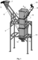
Fig. 1 is a general view of the equipment of the present invention for the ultrasonic washing of the plastic waste; -
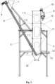
Fig. 2 is a cross-sectional side view of the plastic waste ultrasonic washing equipment of the present invention; -
Fig. 3 1 is a cross-sectional view of the plastic waste ultrasonic washing tank of the present invention through the line A-A offig. 1 . - As shown in the figures, the ultrasonic equipment for washing of the floating plastic waste with a density lower than water, such as, for example, polyethilene (PE) film chips, comprises:
- a vertical metal segmental plastic
waste washing tank 1 of rectangular cross-section, assembled from separate segments 1.1, 1.2 and 1.3 vertically connected to each other by screw connections, with integrated plastic wasteultrasonic washing modules - a
frame 5 for supporting the plasticwaste washing tank 1, - the
spiral conveyor 6, directed from above diagonally down to the bottom of the plasticwaste washing tank 1, for feeding the plastic waste into thewashing tank 1 from the bottom of thetank 1, - plastic
waste loading container 7, installed at the upper end of the plastic wastespiral feed conveyor 6 and being in liquid communication with the plastic wastespiral feeding conveyor 6, - the
screw conveyor 8 for the discharging the washed plastic waste that has risen to the surface of thewashing tank 1, -
engines conveyors - deflecting
elements 11 installed inside each segment 1.1, 1.2, 1.3 of the plasticwaste washing tank 1 between theultrasonic modules washing tank 1 and direct the flow of the plastic waste rising up thewashing tank 1 closest to the zone of cavitation/vibration generated byultrasound modules - an
outlet 12 for the removal from thewashing tank 1 of dirt separated and settled to the bottom of thewashing tank 1 during the washing of the plastic waste, - an
inlet 13 for replenishing the plasticwaste washing tank 1 with washing liquid. - As shown in the attached figures, the
tank 1 for ultrasonic cleaning of plastic waste is assembled from separate segments 1.1, 1.2 and 1.3, vertically connected to each other by screw connections with spacers, mounted on a supportingframe 5. Assembling thewashing tank 1 from separate segments 1.1, 1.2, 1.3 allows, in the event of a breakdown or technical service, after draining the plastic waste washing liquid from thewashing tank 1, to carry out the necessary maintenance or repair work. The number of segments 1.1, 1.2, 1.3 may vary depending on the desired efficiency of the plastic waste washing equipment. - The speed of gears of the
spiral 6 andscrew 8 conveyors and, at the same time, the efficiency of the plastic waste washing equipment is controlled bymotors spiral conveyor 6, having a spiral 6a placed inside a cylindrical body 6b, is used to feed the plastic waste into thewashing tank 1. The spiral 6a of the feedingconveyor 6 is made of a thick twisted wire of rectangular cross-section. Since the spiral screw is a hollow structural element, the use of the feedingconveyor 6 of such a structure with the spiral 6a inside the cylindrical body 6b prevents the clogging of the feedingconveyor 6 with the plastic waste. - The length, diameter and inclination angle of the plastic waste
spiral feeding conveyor 6 are selected so that the upper end of the plasticwaste feeding conveyor 6 is above the vertical plasticwaste washing tank 1 filled with water or any other kind of washing liquid. In the optimal case, the angle α of the inclination of thespiral feeding conveyor 6 with respect to the horizontal is about 60°. This prevents the washing liquid in thewashing tank 1 from entering the upstream plastic waste processing steps, such as shredding. The spiral plasticwaste feeding conveyor 6 and the plasticwaste washing tank 1 are intercommunicating vessels, so the water level in the spiral plasticwaste feeding conveyor 6 is the same as that in the plasticwaste washing tank 1. - The density of the floating plastic waste, major part of which consists of PE films, is about 920 kg/m3, i.e. is smaller than that of water, so the plastic waste fed by the
spiral feeding conveyor 6 to the bottom of the plasticwaste washing tank 1 automatically rises to the surface of the washing liquid. To wash the rising plastic waste, the ultrasonic cavitation generated byultrasound modules ultrasonic modules waste washing tank 1, and are electrically connected to ultrasonic generators installed outside the washing equipment in a separate cabinet. The design of the plasticwaste washing tank 1 was chosen so that it was possible to attach the ultrasonic modules available on the market to the walls of the washing tank segments 1.1, 1.2, 1.3 and create a power of about 10W/l, which corresponds to the power used by most manufacturers of ultrasonic cleaning equipment. - In order for plastic waste to be qualitatively processed by ultrasound, it must be in the intense ultrasound field for a sufficient amount time, i.e. from one to several minutes. The equipment, as it has been mentioned, relates to the washing of floating plastic waste whose density is lower than that of water or other washing liquid. The main technical problem that hinders the effective ultrasonic treatment of the floating plastic waste is the rapid rise to the surface of plastic waste placed in water in the ultrasonic field. During the development of the plastic waste ultrasonic washing equipment of the present invention, several methods were evaluated to slow down to acceptable values the spontaneous movement of the plastic waste up the washing liquid. One of them was to crush the plastic waste to particles smaller than 20 mm, thereby slowing down the spontaneous movement of the plastic waste up through the liquid. However, such shredding turned out to be technologically too expensive. Another method for controlling the upward movement of plastic waste, which was evaluated during the development of the device prototype, was the placement of a horizontally rotating propeller in the lower segment of the plastic waste washing tank between the lower ultrasonic modules. A digital model of the equipment thus modified showed that mixing of the plastic waste washing liquid can reduce the upward movement of the plastic waste particles to the surface by about 10 times. However, it was discovered that the efficiency of cavitation and, at the same time, the washing quality in intensive liquid flow significantly decreases, and the material feeding into the liquid must be at a low flow rate, without causing liquid flow turbulences.
- Therefore, it was decided to install
additional deflecting elements 11, which passively slow down the rise of plastic waste up thewashing tank 1 and additionally direct the plastic waste towards theultrasonic modules elements 11 consist of deflectingplates 11 installed in pairs inside thewashing tank 1 in each segment 1.1, 1.2, 1.3 between theultrasonic modules plates 11 are inclined so as to form an angle β between 15-20° with respect to the vertical, and their upper ends are directed in opposite directions from each other towards therespective ultrasound modules plates 11 creates a passive barrier to the upward movement of the flow of plastic waste within the washing liquid and additionally directs the flow of plastic waste closer to theultrasonic modules - The
screw conveyor 8, that is designed to discharge the plastic waste that has risen to the surface of thewashing tank 1, is installed at the top of the plasticwaste washing tank 1 and is in liquid communication with the plasticwaste washing tank 1. The upper discharge end of thescrew conveyor 8 is raised slightly above the level of the washing liquid in the plasticwaste washing tank 1 and lifted up so that thescrew conveyor 8 forms an angle of about 10° with the horizontal. Such a design ensures that the washing liquid in thescrew discharge conveyor 8 does not go outside but remains inside thewashing tank 1. - According to the results of laboratory measurements, the humidity of the plastic waste fed into the
washing tank 1 is in the range of 1-2%, while the humidity of the washed and discharged plastic waste reaches 57-76%. Since a part of the washing liquid in the plasticwaste washing tank 1 is removed together with the discharged plastic waste, the washing liquid is constantly manually added to thetank 1 through the washingliquid inlet 13 with the help of thevalve 14. - An additional shower washing of the plastic waste can be applied to the upper part of the
discharge conveyor 8 for additional washing/rinsing of the plastic waste. The dirty water is removed through anipple 15, arranged at the bottom end of thescrew discharge conveyor 8, connected to a water removal hose. - The dirt separated during ultrasonic cavitation from the surface of the plastic waste and accumulated at the bottom of the
washing tank 1 is periodically removed from the plasticwaste washing tank 1 through theoutlet 12, arranged at the bottom of the plasticwaste washing tank 1, using a two-valve system.
Claims (4)
- An equipment for ultrasonic washing of floating plastic waste, comprising a plastic waste washing tank arranged on a supporting frame, conveyors for feeding plastic waste into the washing tank and discharging the plastic waste from the washing tank, ultrasound generating devices, characterised in comprising- a vertical plastic waste washing tank (1) assembled from separate metal segments (1.1, 1.2, 1.3) of rectangular cross section vertically connected to each other by screw connections and having ultrasonic plastic waste washing modules (2, 3, 4) attached to internal surfaces of the opposite walls of each segment (1.1, 1.2, 1.3),- a spiral conveyor (6) with a container (7) for feeding the floating plastic waste into the washing tank (1), directed at an angle of about 60° from the top diagonally down to the bottom of the plastic waste washing tank (1),- a screw conveyor (8) for discharging the washed plastic waste from the washing tank (1), installed at the top of the plastic waste washing tank (1) and being in liquid communication with the plastic waste washing tank (1),- deflecting elements (11) installed inside each segment (1.1, 1.2, 1.3) of the plastic waste washing tank (1) between the ultrasonic modules (2, 3, 4), designed to passively slow down the rise of the floating plastic waste through the washing liquid to the top of the washing tank (1) and direct the flow of the plastic waste rising up the washing tank (1) closest to the zone of cavitation/vibration generated by the ultrasound modules (2, 3, 4),- an outlet (12) for the removal from the washing tank (1) of dirt separated and settled to the bottom of the washing tank (1) during the washing of the plastic waste,- an inlet (13) for refilling the plastic waste washing tank (1) with washing liquid.
- The equipment according to claim 1, characterised in that the upper end of the discharge screw conveyor (8) is raised slightly above the level of the washing liquid in the plastic waste washing tank (1) so that the screw conveyor (8) forms an angle of about 10° with the horizontal.
- The equipment according to claim 1, characterised in that the deflecting elements (11) are deflecting plates (11) installed in pairs inside in the each segment (1.1, 1.2, 1.3) of the washing tank (1) between the ultrasonic modules (2, 3, 4) and inclined vertically at an angle β with their upper ends directed towards the respective ultrasound modules (2, 3, 4).
- The equipment according to claim 2, characterised in that the angle β is in the range between 15-20°.
Applications Claiming Priority (1)
| Application Number | Priority Date | Filing Date | Title |
|---|---|---|---|
| LT2022529A LT7050B (en) | 2022-07-26 | 2022-07-26 | FLOATING PLASTIC WASTE WASHING DEVICE WITH ULTRASOUND |
Publications (2)
| Publication Number | Publication Date |
|---|---|
| EP4327947A2 true EP4327947A2 (en) | 2024-02-28 |
| EP4327947A3 EP4327947A3 (en) | 2024-04-10 |
Family
ID=87418626
Family Applications (1)
| Application Number | Title | Priority Date | Filing Date |
|---|---|---|---|
| EP23185778.0A Withdrawn EP4327947A3 (en) | 2022-07-26 | 2023-07-17 | Equipment for washing the floating plastic waste using ultrasound |
Country Status (2)
| Country | Link |
|---|---|
| EP (1) | EP4327947A3 (en) |
| LT (1) | LT7050B (en) |
Citations (1)
| Publication number | Priority date | Publication date | Assignee | Title |
|---|---|---|---|---|
| CN108160606A (en) | 2018-01-05 | 2018-06-15 | 江西龙再生资源有限公司 | A kind of cleaning product line using ultrasonic cleaning polyester chips |
Family Cites Families (2)
| Publication number | Priority date | Publication date | Assignee | Title |
|---|---|---|---|---|
| CN103128075A (en) * | 2011-11-22 | 2013-06-05 | 张家港市贝尔机械有限公司 | Ultrasonic wave cleaning machine |
| CN205085083U (en) * | 2015-11-06 | 2016-03-16 | 浙江华菲再生资源有限公司 | Rinse -system of PET bottle piece |
-
2022
- 2022-07-26 LT LT2022529A patent/LT7050B/en unknown
-
2023
- 2023-07-17 EP EP23185778.0A patent/EP4327947A3/en not_active Withdrawn
Patent Citations (1)
| Publication number | Priority date | Publication date | Assignee | Title |
|---|---|---|---|---|
| CN108160606A (en) | 2018-01-05 | 2018-06-15 | 江西龙再生资源有限公司 | A kind of cleaning product line using ultrasonic cleaning polyester chips |
Also Published As
| Publication number | Publication date |
|---|---|
| LT7050B (en) | 2024-02-26 |
| EP4327947A3 (en) | 2024-04-10 |
| LT2022529A (en) | 2024-02-12 |
Similar Documents
| Publication | Publication Date | Title |
|---|---|---|
| US3765532A (en) | Wood chip washer | |
| EP4327947A2 (en) | Equipment for washing the floating plastic waste using ultrasound | |
| JP2015037759A (en) | Floating grain washer | |
| JP4825850B2 (en) | Floating separator, rectifier, and split cell for rectifier | |
| CN209237512U (en) | A kind of double-chamber type lautertuns being convenient to clean | |
| GB1580124A (en) | Method and apparatus for cleansing soiled chips of synthetic plastics material | |
| JP6518811B2 (en) | Washing method, washing device, operating method of washing device | |
| US5116492A (en) | Apparatus for clarification of industrial sewage | |
| KR102406062B1 (en) | Seaweed cleaning device of removable microplastic | |
| KR20040053010A (en) | Ultrasonic cleaning Dissolved sludge flotation | |
| CN110947689B (en) | Cup cleaning device and cup cleaning system | |
| US3215276A (en) | Adjustable baffle grit chamber | |
| CN215142743U (en) | Circuit board immersion cleaning device | |
| JP2003205248A (en) | Batch washing/flowing method | |
| KR102070832B1 (en) | Filtering system for cleansing liquid | |
| KR860002199B1 (en) | Sand filtration device | |
| JP5886518B2 (en) | Levitation separator | |
| JPH0838927A (en) | Purifying device for sand having gas introduction part in lower range and purification method using this purifying device | |
| KR100526214B1 (en) | A Wafer Cleaning Device Using Megasonic | |
| JP4625291B2 (en) | Sludge treatment equipment | |
| CN224157020U (en) | A flotation machine for splash-proof ore | |
| JP5524775B2 (en) | Levitation separator | |
| CN218709358U (en) | Dissolved air flotation machine | |
| CN217069251U (en) | Metal ore flotation device | |
| CN215965359U (en) | A pipette belt cleaning device for stem cell research |
Legal Events
| Date | Code | Title | Description |
|---|---|---|---|
| PUAI | Public reference made under article 153(3) epc to a published international application that has entered the european phase |
Free format text: ORIGINAL CODE: 0009012 |
|
| STAA | Information on the status of an ep patent application or granted ep patent |
Free format text: STATUS: THE APPLICATION HAS BEEN PUBLISHED |
|
| AK | Designated contracting states |
Kind code of ref document: A2 Designated state(s): AL AT BE BG CH CY CZ DE DK EE ES FI FR GB GR HR HU IE IS IT LI LT LU LV MC ME MK MT NL NO PL PT RO RS SE SI SK SM TR |
|
| PUAL | Search report despatched |
Free format text: ORIGINAL CODE: 0009013 |
|
| AK | Designated contracting states |
Kind code of ref document: A3 Designated state(s): AL AT BE BG CH CY CZ DE DK EE ES FI FR GB GR HR HU IE IS IT LI LT LU LV MC ME MK MT NL NO PL PT RO RS SE SI SK SM TR |
|
| RIC1 | Information provided on ipc code assigned before grant |
Ipc: B08B 3/12 20060101ALI20240306BHEP Ipc: B03B 5/36 20060101ALI20240306BHEP Ipc: B03B 5/28 20060101AFI20240306BHEP |
|
| STAA | Information on the status of an ep patent application or granted ep patent |
Free format text: STATUS: THE APPLICATION IS DEEMED TO BE WITHDRAWN |
|
| 18D | Application deemed to be withdrawn |
Effective date: 20241011 |