EP4327929B1 - Methanolsynthese-plattenreaktor - Google Patents
Methanolsynthese-plattenreaktor Download PDFInfo
- Publication number
- EP4327929B1 EP4327929B1 EP22192285.9A EP22192285A EP4327929B1 EP 4327929 B1 EP4327929 B1 EP 4327929B1 EP 22192285 A EP22192285 A EP 22192285A EP 4327929 B1 EP4327929 B1 EP 4327929B1
- Authority
- EP
- European Patent Office
- Prior art keywords
- process unit
- methanol
- plate
- stream
- product stream
- Prior art date
- Legal status (The legal status is an assumption and is not a legal conclusion. Google has not performed a legal analysis and makes no representation as to the accuracy of the status listed.)
- Active
Links
Images



Classifications
-
- B—PERFORMING OPERATIONS; TRANSPORTING
- B01—PHYSICAL OR CHEMICAL PROCESSES OR APPARATUS IN GENERAL
- B01J—CHEMICAL OR PHYSICAL PROCESSES, e.g. CATALYSIS OR COLLOID CHEMISTRY; THEIR RELEVANT APPARATUS
- B01J8/00—Chemical or physical processes in general, conducted in the presence of fluids and solid particles; Apparatus for such processes
- B01J8/02—Chemical or physical processes in general, conducted in the presence of fluids and solid particles; Apparatus for such processes with stationary particles, e.g. in fixed beds
- B01J8/04—Chemical or physical processes in general, conducted in the presence of fluids and solid particles; Apparatus for such processes with stationary particles, e.g. in fixed beds the fluid passing successively through two or more beds
- B01J8/0446—Chemical or physical processes in general, conducted in the presence of fluids and solid particles; Apparatus for such processes with stationary particles, e.g. in fixed beds the fluid passing successively through two or more beds the flow within the beds being predominantly vertical
- B01J8/0449—Chemical or physical processes in general, conducted in the presence of fluids and solid particles; Apparatus for such processes with stationary particles, e.g. in fixed beds the fluid passing successively through two or more beds the flow within the beds being predominantly vertical in two or more cylindrical beds
- B01J8/0453—Chemical or physical processes in general, conducted in the presence of fluids and solid particles; Apparatus for such processes with stationary particles, e.g. in fixed beds the fluid passing successively through two or more beds the flow within the beds being predominantly vertical in two or more cylindrical beds the beds being superimposed one above the other
-
- B—PERFORMING OPERATIONS; TRANSPORTING
- B01—PHYSICAL OR CHEMICAL PROCESSES OR APPARATUS IN GENERAL
- B01J—CHEMICAL OR PHYSICAL PROCESSES, e.g. CATALYSIS OR COLLOID CHEMISTRY; THEIR RELEVANT APPARATUS
- B01J8/00—Chemical or physical processes in general, conducted in the presence of fluids and solid particles; Apparatus for such processes
- B01J8/02—Chemical or physical processes in general, conducted in the presence of fluids and solid particles; Apparatus for such processes with stationary particles, e.g. in fixed beds
- B01J8/04—Chemical or physical processes in general, conducted in the presence of fluids and solid particles; Apparatus for such processes with stationary particles, e.g. in fixed beds the fluid passing successively through two or more beds
- B01J8/0446—Chemical or physical processes in general, conducted in the presence of fluids and solid particles; Apparatus for such processes with stationary particles, e.g. in fixed beds the fluid passing successively through two or more beds the flow within the beds being predominantly vertical
-
- B—PERFORMING OPERATIONS; TRANSPORTING
- B01—PHYSICAL OR CHEMICAL PROCESSES OR APPARATUS IN GENERAL
- B01J—CHEMICAL OR PHYSICAL PROCESSES, e.g. CATALYSIS OR COLLOID CHEMISTRY; THEIR RELEVANT APPARATUS
- B01J19/00—Chemical, physical or physico-chemical processes in general; Their relevant apparatus
- B01J19/24—Stationary reactors without moving elements inside
- B01J19/248—Reactors comprising multiple separated flow channels
- B01J19/249—Plate-type reactors
-
- B—PERFORMING OPERATIONS; TRANSPORTING
- B01—PHYSICAL OR CHEMICAL PROCESSES OR APPARATUS IN GENERAL
- B01J—CHEMICAL OR PHYSICAL PROCESSES, e.g. CATALYSIS OR COLLOID CHEMISTRY; THEIR RELEVANT APPARATUS
- B01J8/00—Chemical or physical processes in general, conducted in the presence of fluids and solid particles; Apparatus for such processes
- B01J8/02—Chemical or physical processes in general, conducted in the presence of fluids and solid particles; Apparatus for such processes with stationary particles, e.g. in fixed beds
- B01J8/0285—Heating or cooling the reactor
-
- B—PERFORMING OPERATIONS; TRANSPORTING
- B01—PHYSICAL OR CHEMICAL PROCESSES OR APPARATUS IN GENERAL
- B01J—CHEMICAL OR PHYSICAL PROCESSES, e.g. CATALYSIS OR COLLOID CHEMISTRY; THEIR RELEVANT APPARATUS
- B01J8/00—Chemical or physical processes in general, conducted in the presence of fluids and solid particles; Apparatus for such processes
- B01J8/02—Chemical or physical processes in general, conducted in the presence of fluids and solid particles; Apparatus for such processes with stationary particles, e.g. in fixed beds
- B01J8/04—Chemical or physical processes in general, conducted in the presence of fluids and solid particles; Apparatus for such processes with stationary particles, e.g. in fixed beds the fluid passing successively through two or more beds
- B01J8/0446—Chemical or physical processes in general, conducted in the presence of fluids and solid particles; Apparatus for such processes with stationary particles, e.g. in fixed beds the fluid passing successively through two or more beds the flow within the beds being predominantly vertical
- B01J8/0476—Chemical or physical processes in general, conducted in the presence of fluids and solid particles; Apparatus for such processes with stationary particles, e.g. in fixed beds the fluid passing successively through two or more beds the flow within the beds being predominantly vertical in two or more otherwise shaped beds
- B01J8/048—Chemical or physical processes in general, conducted in the presence of fluids and solid particles; Apparatus for such processes with stationary particles, e.g. in fixed beds the fluid passing successively through two or more beds the flow within the beds being predominantly vertical in two or more otherwise shaped beds the beds being superimposed one above the other
-
- B—PERFORMING OPERATIONS; TRANSPORTING
- B01—PHYSICAL OR CHEMICAL PROCESSES OR APPARATUS IN GENERAL
- B01J—CHEMICAL OR PHYSICAL PROCESSES, e.g. CATALYSIS OR COLLOID CHEMISTRY; THEIR RELEVANT APPARATUS
- B01J8/00—Chemical or physical processes in general, conducted in the presence of fluids and solid particles; Apparatus for such processes
- B01J8/02—Chemical or physical processes in general, conducted in the presence of fluids and solid particles; Apparatus for such processes with stationary particles, e.g. in fixed beds
- B01J8/04—Chemical or physical processes in general, conducted in the presence of fluids and solid particles; Apparatus for such processes with stationary particles, e.g. in fixed beds the fluid passing successively through two or more beds
- B01J8/0492—Feeding reactive fluids
-
- B—PERFORMING OPERATIONS; TRANSPORTING
- B01—PHYSICAL OR CHEMICAL PROCESSES OR APPARATUS IN GENERAL
- B01J—CHEMICAL OR PHYSICAL PROCESSES, e.g. CATALYSIS OR COLLOID CHEMISTRY; THEIR RELEVANT APPARATUS
- B01J8/00—Chemical or physical processes in general, conducted in the presence of fluids and solid particles; Apparatus for such processes
- B01J8/02—Chemical or physical processes in general, conducted in the presence of fluids and solid particles; Apparatus for such processes with stationary particles, e.g. in fixed beds
- B01J8/04—Chemical or physical processes in general, conducted in the presence of fluids and solid particles; Apparatus for such processes with stationary particles, e.g. in fixed beds the fluid passing successively through two or more beds
- B01J8/0496—Heating or cooling the reactor
-
- C—CHEMISTRY; METALLURGY
- C07—ORGANIC CHEMISTRY
- C07C—ACYCLIC OR CARBOCYCLIC COMPOUNDS
- C07C29/00—Preparation of compounds having hydroxy or O-metal groups bound to a carbon atom not belonging to a six-membered aromatic ring
- C07C29/15—Preparation of compounds having hydroxy or O-metal groups bound to a carbon atom not belonging to a six-membered aromatic ring by reduction of oxides of carbon exclusively
- C07C29/151—Preparation of compounds having hydroxy or O-metal groups bound to a carbon atom not belonging to a six-membered aromatic ring by reduction of oxides of carbon exclusively with hydrogen or hydrogen-containing gases
- C07C29/152—Preparation of compounds having hydroxy or O-metal groups bound to a carbon atom not belonging to a six-membered aromatic ring by reduction of oxides of carbon exclusively with hydrogen or hydrogen-containing gases characterised by the reactor used
-
- B—PERFORMING OPERATIONS; TRANSPORTING
- B01—PHYSICAL OR CHEMICAL PROCESSES OR APPARATUS IN GENERAL
- B01J—CHEMICAL OR PHYSICAL PROCESSES, e.g. CATALYSIS OR COLLOID CHEMISTRY; THEIR RELEVANT APPARATUS
- B01J2208/00—Processes carried out in the presence of solid particles; Reactors therefor
- B01J2208/00008—Controlling the process
- B01J2208/00017—Controlling the temperature
- B01J2208/00106—Controlling the temperature by indirect heat exchange
- B01J2208/00115—Controlling the temperature by indirect heat exchange with heat exchange elements inside the bed of solid particles
- B01J2208/0015—Plates; Cylinders
-
- B—PERFORMING OPERATIONS; TRANSPORTING
- B01—PHYSICAL OR CHEMICAL PROCESSES OR APPARATUS IN GENERAL
- B01J—CHEMICAL OR PHYSICAL PROCESSES, e.g. CATALYSIS OR COLLOID CHEMISTRY; THEIR RELEVANT APPARATUS
- B01J2208/00—Processes carried out in the presence of solid particles; Reactors therefor
- B01J2208/00008—Controlling the process
- B01J2208/00017—Controlling the temperature
- B01J2208/00106—Controlling the temperature by indirect heat exchange
- B01J2208/00168—Controlling the temperature by indirect heat exchange with heat exchange elements outside the bed of solid particles
- B01J2208/00212—Plates; Jackets; Cylinders
- B01J2208/0023—Plates; Jackets; Cylinders with some catalyst tubes being empty, e.g. dummy tubes or flow-adjusting rods
-
- B—PERFORMING OPERATIONS; TRANSPORTING
- B01—PHYSICAL OR CHEMICAL PROCESSES OR APPARATUS IN GENERAL
- B01J—CHEMICAL OR PHYSICAL PROCESSES, e.g. CATALYSIS OR COLLOID CHEMISTRY; THEIR RELEVANT APPARATUS
- B01J2208/00—Processes carried out in the presence of solid particles; Reactors therefor
- B01J2208/02—Processes carried out in the presence of solid particles; Reactors therefor with stationary particles
- B01J2208/021—Processes carried out in the presence of solid particles; Reactors therefor with stationary particles comprising a plurality of beds with flow of reactants in parallel
- B01J2208/022—Plate-type reactors filled with granular catalyst
-
- B—PERFORMING OPERATIONS; TRANSPORTING
- B01—PHYSICAL OR CHEMICAL PROCESSES OR APPARATUS IN GENERAL
- B01J—CHEMICAL OR PHYSICAL PROCESSES, e.g. CATALYSIS OR COLLOID CHEMISTRY; THEIR RELEVANT APPARATUS
- B01J2219/00—Chemical, physical or physico-chemical processes in general; Their relevant apparatus
- B01J2219/24—Stationary reactors without moving elements inside
- B01J2219/2401—Reactors comprising multiple separate flow channels
- B01J2219/245—Plate-type reactors
- B01J2219/2451—Geometry of the reactor
- B01J2219/2453—Plates arranged in parallel
-
- B—PERFORMING OPERATIONS; TRANSPORTING
- B01—PHYSICAL OR CHEMICAL PROCESSES OR APPARATUS IN GENERAL
- B01J—CHEMICAL OR PHYSICAL PROCESSES, e.g. CATALYSIS OR COLLOID CHEMISTRY; THEIR RELEVANT APPARATUS
- B01J2219/00—Chemical, physical or physico-chemical processes in general; Their relevant apparatus
- B01J2219/24—Stationary reactors without moving elements inside
- B01J2219/2401—Reactors comprising multiple separate flow channels
- B01J2219/245—Plate-type reactors
- B01J2219/2476—Construction materials
- B01J2219/2477—Construction materials of the catalysts
- B01J2219/2481—Catalysts in granular from between plates
Definitions
- the invention relates to a methanol synthesis reactor, in particular a methanol synthesis reactor comprising at least two integrated process units.
- the individual process steps take place in separate individual units or devices.
- these process steps consist at least of the reaction of synthesis gas to methanol, the cooling of the reaction mixture to condense crude methanol, and the separation (separation) of the condensed crude methanol from the unreacted synthesis gas (residual gas) and inert components of the gas mixture.
- the process media of the process unit are introduced through nozzles into a pressure device and from there into the respective internal device components, where they are distributed or collected, and then discharged. This occurs through dedicated device openings and internals for the respective device, as well as through connecting elements such as pipelines and valves, and, depending on the relative position of the process units, through additional conveying devices such as pumps.
- JP S60 168530 A discloses a methanol synthesis reactor comprising several reaction tubes filled with a catalyst, which are divided into several upper and lower stages.
- the gas to be reacted is passed through the reaction tubes in series, while the outer surface of each reaction tube is brought into contact with water for cooling.
- the temperature of the water, which is in contact with the outer surface of a downstream reaction tube is kept at a lower temperature than the water that comes into contact with the outer surface of an upstream reaction tube.
- US 4,743,432 A discloses a vertically arranged reactor for producing methanol.
- This reactor comprises a cylindrical housing with exchanger tubes penetrating the catalyst bed inside the housing, as well as a gas-permeable floor or mesh supporting the catalyst bed in the lower reactor section.
- Horizontal, gas-impermeable partition walls are arranged below the gas-permeable floor or mesh of the second-lowest and the next-highest catalyst bed at the level of the gas inlet or outlet openings.
- US 2002/048541 A1 discloses a reactor for conducting a highly exothermic catalytic reaction in a process fluid, equipped with plates arranged parallel to one another at a distance from one another, forming flat channels in opposing lateral boundary surfaces.
- One part of the channels contains a solid catalyst and conducts the process fluid, and another part of the channels carries a heat transfer medium in indirect thermal contact with the process fluid.
- the plates are flat or provided with grooves or ribs, and the plates are at least partially coated with the catalyst on the surface facing the process fluid.
- US 5 874 051 A discloses a method and apparatus for the selective catalytic oxidation of carbon monoxide.
- a gas mixture and an additionally added oxidizing gas are passed through a reactor containing the catalyst.
- the oxidizing gas is added at several points along the mixed gas stream at a controlled or regulated flow volume.
- the mixed gas stream is passively cooled by static mixing structures in the inlet region of the oxidation reactor.
- An object of the present invention is to at least partially overcome the aforementioned disadvantages of the prior art.
- a further object of the present invention is to provide a reactor for the synthesis of methanol, which makes it possible to reduce the number of connecting pipelines, individual pressure jackets and apparatus floors.
- a further object of the present invention is to provide a reactor for the synthesis of methanol, which fulfills at least two process functions and has the smallest possible total volume and the smallest possible total surface area.
- a further object of the present invention is to provide a reactor for the synthesis of methanol which requires the shortest possible total production time with respect to the fulfillment of at least two process functions.
- a further object of the present invention is to provide a reactor for the synthesis of methanol which requires as few or no conveying devices as possible with respect to the process functions to be performed.
- Another object of the present invention is to provide a reactor for the synthesis of methanol, which is designed to minimize material stresses in the metal-based components.
- a “multiplicity" of plates is understood to mean a plurality of plates, but preferably more than two plates, in particular at least 5 plates, or at least 10 plates, or at least 25 plates, or at least 50 plates.
- the at least two process units in the interior of the pressure jacket include the first and the second process unit.
- a pressure shell is understood to be an enveloping structure that can withstand higher internal pressures, in particular internal pressures significantly above atmospheric pressure, for example, pressures of more than 5 bar.
- the first process unit functions as a reactor stage for synthesizing methanol from a synthesis gas stream that can be introduced into the reactor stage, referred to here as reactor stage RS1.
- the first process unit is designed as a plate heat exchanger.
- the first process unit has a plate heat exchanger structure.
- Two adjacent plates of the plate heat exchanger are spaced apart from each other in such a way that a plate gap is formed between two adjacent plates.
- a solid methanol synthesis catalyst is arranged in the interstices of the plate of the first process unit.
- the entire methanol synthesis catalyst arranged in the interstices of the plate of the first process unit forms the catalyst bed, referred to here as catalyst bed CB1.
- the methanol synthesis catalyst is a methanol synthesis catalyst known to those skilled in the art, for example, a copper-based one.
- the methanol synthesis catalyst can be configured, for example, as a bed or structured packing.
- the plate spaces containing the methanol synthesis catalyst are configured so that the synthesis gas stream and the product stream RP1 can flow through them from top to bottom.
- the first process unit comprises means configured so that the spaces between the plates can be flowed through from top to bottom with the synthesis gas stream and the product stream RP1.
- the product stream RP1 can also flow through the interstices between the plates from top to bottom.
- the methanol-containing product stream RP1 is cooled in countercurrent by the first cooling medium stream CM1 flowing through the plate interiors from bottom to top.
- the synthesis gas of the synthesis gas stream comprises a carbon oxide, i.e., carbon monoxide or carbon dioxide, or a mixture thereof. Furthermore, the synthesis gas of the synthesis gas stream comprises hydrogen. Furthermore, the synthesis gas may generally contain inert components or components that are inert under the conditions of methanol synthesis. Examples are nitrogen or methane.
- the product stream RP1 comprises at least methanol and water as condensable components, as well as possibly undesired condensable and non-condensable by-products. Furthermore, the product stream RP1 may contain unconverted synthesis gas.
- the plates of the first process unit have flow-through interiors.
- a first cooling medium flow CM1 flows through the interiors of the plates.
- the first process unit is configured so that the first cooling medium flow CM1 flows through the interiors of the plates from bottom to top.
- the first process unit has means which are configured such that the cooling medium flow CM1 can flow through the plate interiors from bottom to top.
- the plate interiors of the first process unit can preferably be flowed through in a vertical direction, in particular in a vertical direction from bottom to top by the first cooling medium flow.
- the spaces between the plates of the first process unit can preferably be flowed through in the vertical direction, in particular in the vertical direction from top to bottom by the synthesis gas stream and the product stream RP1.
- the second process unit fulfils either the function of a cooling stage or the function of a second reactor stage RS2.
- the methanol-containing product stream RP1 can be withdrawn from the first process unit, which is configured as reactor stage RS1, and fed into the second process unit.
- this product stream RP1 is either cooled (alternative c1) or further converted to a methanol-containing product stream RP2 (alternative c2).
- unconverted synthesis gas i.e., remaining synthesis gas or residual gas, in the methanol-containing product stream RP1 is converted to methanol.
- the second process unit is also designed as a plate heat exchanger.
- the second process unit has a plate heat exchanger structure.
- Two adjacent plates of the plate heat exchanger are spaced apart from each other in such a way that a plate gap is formed between two adjacent plates.
- the plates have flow-through interiors through which a second cooling medium flow CM2 flows.
- the second process unit is configured so that the second cooling medium flow CM2 flows through the plate interiors from bottom to top.
- the first process unit has means which are configured such that the plate interiors can be flowed through by the second cooling medium flow CM2 from bottom to top.
- the plate interiors of the second process unit can preferably be flowed through in the vertical direction by the second cooling medium flow CM2, in particular in the vertical direction from bottom to top by the second cooling medium flow.
- the second process unit is designed as a cooling stage.
- the methanol-containing product stream RP1 flows through the plate interstices of the second process unit from top to bottom.
- the second process unit according to alternative c1 has means configured such that the methanol-containing product stream RP1 flows through the plate interstices from top to bottom.
- the methanol-containing product stream RP1 preferably flows through the plate interstices in a vertical direction.
- the methanol-containing product stream RP1 is cooled by the second cooling medium stream CM2 flowing through the plate interiors from bottom to top.
- the second process unit according to alternative c1 is configured such that the methanol-containing product stream RP1 is cooled to such an extent that condensation of methanol and water from the methanol-containing product stream RP1 occurs.
- the second process unit is designed as reactor stage RS2.
- a solid methanol synthesis catalyst is arranged in the interstices of the plate of the second process unit.
- the entire methanol synthesis catalyst arranged in the interstices of the plate of the second process unit forms the catalyst bed, referred to here as catalyst bed CB2.
- the methanol synthesis catalyst is a methanol synthesis catalyst known to those skilled in the art, for example, a copper-based one.
- the methanol synthesis catalyst can be configured, for example, as a bed or structured packing.
- the plate spaces containing the methanol synthesis catalyst are configured such that the product stream RP1 and the product stream RP2 can flow through them from top to bottom.
- the second process unit has means configured such that the plate spaces can be flowed through from top to bottom with the product stream RP1 and the product stream RP2.
- An exothermic reaction of product stream RP1 takes place at the methanol synthesis catalyst of catalyst bed CB2. This results in the formation of product stream RP2.
- the interstices between the plates can also be flowed through from top to bottom by product stream RP2.
- the second process unit forms a second reactor stage RS2.
- the synthesis gas contained in product stream RP1 is converted to methanol.
- This synthesis gas could not be converted to methanol in the first reactor stage RS1 due to the formation of the thermodynamic equilibrium typical for methanol synthesis.
- This remaining synthesis gas or residual gas therefore forms part of product stream RP1.
- Product stream RP2 contains at least methanol and water as condensable components, as well as possibly undesired condensable and non-condensable by-products. Furthermore, product stream RP2 may still contain unconverted synthesis gas.
- the methanol-containing product stream RP1 and the methanol-containing product stream RP2 flow through the plate interstices of the second process unit from top to bottom.
- the second process unit according to alternative c2 has means configured such that the methanol-containing product stream RP1 and the methanol-containing product stream RP2 flow through the plate interstices from top to bottom.
- the methanol-containing product stream RP1 and the methanol-containing product stream RP2 preferably flow through the plate interstices in a vertical direction.
- the methanol-containing product stream RP2 is cooled in countercurrent by the second cooling medium stream CM2 flowing through the plate interiors from bottom to top.
- the first and second process units are arranged one above the other within the pressure shell, with the second process unit being arranged below the first process unit. Both process units are fluidically connected to each other.
- the first and second process units are fluidically connected with respect to the synthesis gas flow and the methanol-containing product streams RP1 and RP2 are fluidically connected to each other, in particular on the side of the plate interspaces.
- the first and second processing units are arranged in alignment one behind the other, i.e., along a straight line or axis common to the first and second processing units.
- the second processing unit is therefore not offset from the first processing unit, and vice versa.
- the methanol synthesis reactor is designed as a single-stage reactor with a reactor stage RS1 at the top and a cooling stage at the bottom.
- the methanol synthesis reactor is designed as a two-stage reactor with a first reactor stage RS1 at the top and a second reactor stage RS2 at the bottom.
- the methanol synthesis reactor can further comprise further process units.
- the methanol synthesis reactor according to alternative c1 can have a third process unit configured as a condenser below the second process unit.
- the methanol synthesis reactor according to alternative c1 can have a fourth process unit configured as a gas-liquid separator below the third process unit.
- the methanol synthesis reactor according to alternative c2 can have a third process unit configured as a cooling stage below the second process unit.
- the methanol synthesis reactor according to alternative c2 can have a fourth process unit configured as a condenser below the third process unit.
- the methanol synthesis reactor according to alternative c2 can have a fifth process unit configured as a gas-liquid separator below the fourth process unit.
- the cooling stage is already designed as a condenser, so that complete condensation of condensable products and by-products already takes place in the cooling stage.
- the cooling medium for the first cooling medium stream CM1 and/or second cooling medium stream CM2 can be any suitable gaseous or liquid cooling medium.
- the cooling medium for the first process unit is preferably boiling water, in particular boiling boiler feed water.
- a preferred embodiment of the reactor is therefore characterized in that the first cooling medium stream CM1 comprises boiling boiler feed water.
- the first cooling medium stream CM1 is evaporable as it flows through the plate interiors of the first process unit.
- the first process unit is designed as a water-cooled reactor stage RS1, thus fulfilling the function of a water-cooled reactor stage.
- the cooling medium evaporates primarily due to the thermal energy absorbed during the formation of the methanol-containing product stream RP1.
- the thermal energy required for evaporation corresponds to the evaporation enthalpy of the cooling medium.
- the cooling medium for the second process unit is preferably a gaseous cooling medium.
- the second process unit is configured either as a gas-cooled cooling stage according to alternative c1 or as a gas-cooled reactor stage RS2 according to alternative c2. In the latter case, the second process unit fulfills the function of a gas-cooled reactor stage.
- Figure 5 shows a typical temperature profile of a catalyst bed along the length of a methanol reactor, determined by measurement and simulation. This temperature profile can be spatially divided into four parts from the reactor inlet to the outlet, as explained below.
- the first part of the catalyst bed serves to heat the synthesis gas, with heat being transferred from the coolant to the synthesis gas and the catalyst. This gradually initiates the reaction to form methanol. Due to the exothermic nature of the reaction, heat is generated and the temperature of both the catalyst and the gas mixture (synthesis gas and gaseous methanol/water, as well as unreacted synthesis gas) increases. As the reaction progresses, the temperature of the catalyst bed and the gas mixture approximately corresponds to the temperature of the coolant.
- the reaction continues, generating further heat and further heating the catalyst bed and the gas mixture
- the rate of heat generation in this second part of the catalyst bed is faster than the heat transfer from the coolant, so that the temperatures of the gas mixture and the catalyst bed rise above the temperature of the coolant.
- the heat generated during the reaction first heats the solid catalyst. Heat is then transferred from the catalyst to the process gas mixture to cool the catalyst. The process gas mixture then transfers the heat to the coolant used in the reactor. Another type of heat transfer is thermal convection from the solid catalyst to the reactor internals. The temperature in this part of the catalyst bed continues to rise above that of the coolant.
- the rate of heat production slows as the reaction approaches equilibrium conditions. Heat transfer from the catalyst to the process gas mixture and ultimately to the cooling system continues, allowing the temperature of the catalyst bed to be lowered again.
- the reaction In a final, fourth part of the catalyst bed, the reaction is in equilibrium without significant heat production. In this part of the catalyst bed, the temperature continues to drop toward the coolant temperature.
- the plates are arranged vertically, and the reacting or cooling process gases are guided from top to bottom within the plate gaps.
- the temperature on the plate gap side will thus fall from top to bottom in the broadest sense, thus forming a temperature gradient with a falling temperature from top to bottom over the longest section of the process unit.
- the second process unit is not filled with catalyst, as in the case of alternative c1.
- the temperature of the product stream RP1 in the second process unit decreases continuously from top to bottom over the entire length of the process unit as cooling progresses.
- the density of a medium at higher temperatures is relatively lower than the density of the same medium at lower temperatures, a density gradient develops during reactor operation, with a low density in an upper zone of the reactor or process unit leading to a higher density in a lower zone of the reactor or process unit.
- the intended flow direction of the respective process gas mixture on the plate space side, from top to bottom, is supported by the fact that heavier components (components with a higher density) collect in a lower region of the reactor or process unit due to the effect of gravity.
- the intended flow direction of the respective mixture is also favored by the vertical arrangement of the plates of the process units.
- the advantages of the reactor according to the invention also extend to the guidance of the respective cooling media.
- the cooling media are guided from bottom to top on the inner side of the flow-through plates, while the process gas mixture to be cooled is guided from top to bottom on the inter-plate space side.
- the cooling medium therefore enters the respective process unit in a lower region and exits it in an upper region. In the process, it heats up continuously in the direction of flow from bottom to top due to the cooling of the process gas mixture and/or continuously changes from a liquid phase to a gaseous phase.
- the aforementioned temperature gradient and/or density gradient thus forms not only on the inner side of the plates, but also on the inter-plate space side.
- the thermal energy required for evaporation corresponds to the evaporation enthalpy of the cooling medium. Since the device is hot in an upper zone during operation due to the aforementioned effects, evaporation in the upper zone is favored. As explained above, a density gradient forms on the plate interior side of the first process unit, with a low density in the upper zone and a high density in the lower zone. This leads to the so-called thermosyphon effect, which enables natural circulation of the cooling medium without the need for a forced-flow conveying device as described above.
- the heating cooling medium is "sucked" upwards within the plate interiors of the first and/or second process unit, while the cooling and/or condensing process gas mixture "falls" downwards on the side of the plate interspaces of the first and/or second process unit.
- the temperature gradient formed during operation by the inventive arrangement of the first and second process units and the inventive flow guidance is reflected not only in the flowing media, but also in the metallic structures of the device, since the heat of the media is transferred to the metallic structures. Since the temperature gradient continuously decreases from an upper region to a lower region, and essentially no temperature peaks occur, , potential thermal stresses due to locally occurring large temperature differences are reduced to a minimum.
- the first and second process units as well as the pressure jacket are made in particular of a metal or a metal alloy.
- at least the media-carrying components of the first and second process units and the pressure jacket are made of a metal or a metal alloy.
- An embodiment of the reactor according to the invention is characterized in that the plates of the first process unit and/or the plates of the second process unit are designed as cushion plates.
- Pillow plates instead of conventional straight heat exchanger plates offer advantages, particularly with regard to the device according to the invention, in terms of mechanical stability and heat transfer efficiency.
- An improvement in heat transfer efficiency compared to conventional plates results, in particular, in the generation of steam on the inside of the plates when the nucleation point is reached and the subsequent resulting steam bubble formation.
- Pillow plate heat exchangers for example, are described in more detail in the DE 10 2016 005 999 A1 described.
- An embodiment of the reactor according to the invention is characterized in that the second process unit is configured such that the plate interiors can be flowed through by the synthesis gas stream, wherein the synthesis gas stream fulfills the function of the second cooling medium stream CM2, whereby a preheated synthesis gas stream can be generated.
- An embodiment of the reactor according to the invention is therefore characterized in that the methanol synthesis reactor has means for discharging the preheated synthesis gas stream from the second process unit, as well as means for introducing the preheated synthesis gas stream into the first process unit to produce the methanol-containing product stream RP1.
- An embodiment of the reactor according to the invention is characterized in that the plate interiors of the first process unit and the plate interiors of the second process unit are arranged at least partially in alignment one behind the other and/or the plate interspaces of the first process unit and the plate interspaces of the second process unit are arranged at least partially in alignment one behind the other.
- An aligned arrangement one behind the other means that two plates of the first and second process unit arranged one behind the other in the flow direction of the process media (synthesis gas stream, methanol-containing product stream RP1, methanol-containing product stream RP2) are arranged along these longitudinal axes with respect to the longitudinal axes of their plate interiors or plate interspaces.
- this arrangement takes place without the respective plate of the first process unit being arranged offset from the plate of the second process unit with respect to the respective longitudinal axis.
- the two successively arranged plates of the first and second process unit are arranged in such a way that, with the same cross-sectional areas, they are arranged congruently with respect to these cross-sectional areas, i.e. that their two cross-sectional areas are congruent if they were displaced along the longitudinal axis and brought into alignment.
- the reactor is designed such that the aligned arrangement applies to all plates of the first process unit relative to all plates of the second process unit.
- each plate of the first process unit has a counterpart plate in the second process unit arranged in alignment with it.
- the aligned arrangement allows the volume of the reactor according to the invention to be minimized. In other words, the ratio of the required volume to the available usable area is minimized.
- the usable area is understood to be the area that can be used for cooling the process media with the cooling media or for synthesizing methanol from the process media.
- An embodiment of the reactor according to the invention is characterized in that the methanol synthesis reactor has a support structure, wherein the support structure is designed as a support arranged at least partially below a process unit and/or as a suspension arranged at least partially above a process unit and thereby forms a mechanical connection between a process unit and the pressure shell.
- a “support structure” within the meaning of the invention can alternatively also be referred to as a "support element”.
- the reactor according to the invention preferably has at least one support structure.
- the support structure forms a mechanical connection between a process unit and the pressure shell.
- the mechanical connection represents a fixed point between a process unit and the pressure shell.
- a single support structure may be sufficient for the entire reactor, forming a mechanical connection between a process unit and the pressure shroud. Multiple such support structures may also be required, for example, one support structure per process unit.
- the mechanical connection between the respective process unit and the pressure shroud can be a force-fit connection and/or a material connection.
- An example of a force-locking connection is a screw connection.
- An example of a material-locking connection is a welded joint.
- the support structure is designed as a suspension or as a support.
- the support structure is arranged at least partially, i.e., partially or completely, above the respective process unit.
- the support structure is arranged at least partially, i.e., partially or completely, below the respective process unit.
- the support is arranged completely below a process unit, and the suspension is arranged completely above a process unit.
- the respective support structures not entirely next to a respective process unit, but at least partially above or below a process unit and to mechanically connect them to the respective process unit and the pressure jacket.
- This and especially when arranged entirely above or below a process unit, allows the support structures or connecting elements to be positioned at a location where they do not significantly influence the internal diameter of the reactor.
- Parallel attachment i.e. attachment at the same height of the process unit plates between the process unit and the shell wall, would noticeably increase the cross-section of the reactor, particularly with regard to the diameter of the pressure jacket.
- the pressure jacket would have to be designed with correspondingly thicker walls, which would be disadvantageous.
- the arrangement of the support structures at least partially above and/or at least partially below a process unit, in particular completely above and/or below a process unit enables the design of an individual plate width for each of the heat exchanger plates. This allows a particularly round cross-sectional area (circular area) of the pressure shell to be utilized most effectively.
- An embodiment of the reactor according to the invention is characterized in that the first process unit has a support structure arranged at least partially below the first process unit and designed as a support, and the second process unit has a support structure arranged at least partially above the second process unit and designed as a suspension.
- the first, i.e., upper, process unit is connected to the pressure shroud via a support structure designed as a support.
- the second, i.e., lower, process unit is connected to the pressure shroud via a support structure designed as a suspension.
- Each of the process units thus has a dedicated support structure. In certain reactor configurations, this leads to an advantageous two-part distribution of the loads of the process units within the pressure shroud.
- the support is arranged in the lower region of the first process unit, i.e., in the sump region of the first process unit, and establishes a mechanical connection between the first process unit and the pressure jacket in this region.
- the elements for forming the mechanical connection between the process unit and the pressure jacket are also arranged accordingly, preferably in the lower region or in the sump region of the first process unit.
- the suspension is arranged in the upper region of the second process unit, i.e., at the head region of the second process unit, and establishes a mechanical connection between the second process unit and the pressure jacket in this region.
- the elements for forming the mechanical connection between the process unit and the pressure jacket are also arranged accordingly, preferably in the upper region or at the head region of the second process unit.
- An embodiment of the reactor according to the invention is characterized in that the first process unit has a support structure arranged at least partially above the first process unit and designed as a suspension, and wherein the first and the second process unit are mechanically connected to one another via a connecting element.
- the connecting element does not establish a mechanical connection between the first process unit and the pressure jacket, and does not establish a mechanical connection between the second process unit and the pressure jacket.
- the first, i.e., upper, process unit is connected to the pressure shroud via a support structure designed as a suspension.
- a support structure designed as a suspension only the first process unit has a dedicated support structure. In certain reactor configurations, this leads to an advantageous, one-piece transfer of the loads of both process units downwards within the pressure shroud.
- the suspension is arranged in the upper region of the first process unit, i.e., at the head region of the first process unit, and establishes a mechanical connection between the first process unit and the pressure jacket in this region.
- the elements for forming the mechanical connection between the process unit and the pressure jacket are also arranged accordingly, preferably in the upper region or at the head region of the first process unit.
- the entire construction comprising the heat exchanger plates of the first and second process unit and other components mechanically connected thereto can expand freely downwards when the temperature increases during reactor operation.
- this design can be advantageous, particularly when using boiling boiler feedwater as the cooling medium CM1 for the first process unit.
- the first process unit which is configured as reactor stage RS1
- large quantities of steam are produced on the inside of the plate in certain reactor configurations.
- the steam leaves the first process unit at the head region of the first process unit due to the routing of the coolant CM1 from bottom to top.
- the cooling medium supply line then tends to have a smaller cross-section than the steam-carrying cooling medium discharge line.
- a smaller cross-section is associated with a smaller wall thickness of the supply line, which makes it easier to make the supply line flexible than the discharge line. Accordingly, it is advantageous to make the sump region of the first process unit flexible and the head region rigid.
- the former is achieved by the flexible connecting element between the first and second process units, which is not mechanically connected to the pressure jacket, and the latter by the support structure implemented as a suspension in the head region of the first process unit.
- the cooling medium supply line can be routed parallel to the plates of the first process unit.
- the cooling medium inlet nozzle for the cooling medium CM1 is located in the head area of the first process unit, and the line is then preferably routed vertically downwards.
- An embodiment of the reactor according to the invention is characterized in that the second process unit has a support structure arranged at least partially below the second process unit and designed as a support, and wherein the first and the second process unit are mechanically connected to one another via a connecting element.
- the connecting element does not establish a mechanical connection between the first process unit and the pressure jacket, and does not establish a mechanical connection between the second process unit and the pressure jacket.
- the second, i.e., lower, process unit is connected to the pressure shroud via a support structure designed as a support.
- a support structure designed as a support.
- this leads to an advantageous, one-piece transfer of the loads of both process units upwards within the pressure shroud.
- the support is arranged in the lower region of the second process unit, i.e., in the sump region of the second process unit, and establishes a mechanical connection between the second process unit and the pressure jacket in this region.
- the elements for forming the mechanical connection between the process unit and the pressure jacket are also arranged accordingly, preferably in the lower region or in the sump region of the second process unit.
- the entire construction comprising the heat exchanger plates of the first and second process unit and other components mechanically connected thereto can expand freely upwards when the temperature increases during reactor operation.
- An embodiment of the reactor according to the invention is characterized in that the methanol synthesis reactor has a synthesis gas inlet nozzle extending through the pressure jacket, wherein the synthesis gas inlet nozzle is fluidically connected to the plate interiors of the second process unit and is configured to introduce the synthesis gas stream into the second process unit.
- This embodiment is relevant for the case where the synthesis gas stream is used as a coolant on the inside of the plate of the second process unit.
- the synthesis gas inlet nozzle is then preferably arranged in the sump region of the second process unit and preferably extends horizontally through the pressure jacket.
- An embodiment of the reactor according to the invention is characterized in that the second process unit has a distribution system in its sump region, which is fluidically connected to the synthesis gas inlet nozzle and the plate interiors of the second process unit and is configured to distribute the synthesis gas stream entering via the synthesis gas inlet nozzle to the plate interiors of the second process unit.
- An embodiment of the reactor according to the invention is characterized in that the second process unit comprises a collector system in its head region, which is fluidically connected to the plate interiors of the second process unit and is configured to collect the preheated synthesis gas stream emerging from the plate interiors of the second process unit.
- the second process unit preferably comprises in its head region a collector system which is fluidically connected to the plate interiors of the second process unit and is configured to collect the cooling medium flow CM2 emerging from the plate interiors of the second process unit.
- An embodiment of the reactor according to the invention is characterized in that the first process unit comprises a distribution system in its head region, which is fluidically connected to the collector system of the second process unit and configured to distribute the preheated synthesis gas to the plate spaces of the first process unit.
- the first process unit preferably comprises a distribution system in its head region, which is configured to distribute the synthesis gas of the synthesis gas stream to the plate interspaces of the first process unit.
- An embodiment of the reactor according to the invention is characterized in that the collector system of the second process unit and the distribution system of the first process unit are connected via a line bypassing the first process unit and running at least partially within the pressure jacket.
- This embodiment is relevant when the synthesis gas stream is used as the cooling medium stream CM2 in the second process unit, and the collector system of the first process unit and the distribution system of the first process unit must be connected to each other by a corresponding line. It is then advantageous to lay this line such that it bypasses the first process unit between the pressure jacket and this first process unit, and in particular runs parallel to the plates of the first process unit.
- An embodiment of the reactor according to the invention is characterized in that the methanol synthesis reactor has a cooling medium inlet nozzle extending through the pressure jacket, wherein the cooling medium inlet nozzle is fluidically connected to the plate interiors of the first process unit and is configured to introduce the cooling medium flow CM1 into the first process unit.
- An embodiment of the reactor according to the invention is characterized in that the first process unit has a distribution system in its sump region, which is fluidically connected to the cooling medium inlet nozzle and the plate interiors of the first process unit and is configured to distribute the cooling medium flow CM1 entering via the cooling medium inlet nozzle to the plate interiors of the first process unit.
- the cooling medium stream CM1 preferably comprises boiling boiler feed water with respect to the first process unit.
- An embodiment of the reactor according to the invention is characterized in that the methanol synthesis reactor has a cooling medium outlet nozzle extending through the pressure jacket, wherein the cooling medium outlet nozzle is fluidically connected to the plate interiors of the first process unit and is configured to discharge the cooling medium stream CM1 from the first process unit.
- the discharged cooling medium stream CM1 comprises, in particular, steam.
- An embodiment of the reactor according to the invention is characterized in that the first process unit has a collector system in its head region, which is fluidically connected to the cooling medium outlet nozzle and the plate interiors of the first process unit and is configured to collect the cooling medium flow CM1 emerging from the plate interiors of the first process unit.
- An embodiment of the reactor according to the invention is characterized in that the methanol synthesis reactor comprises a product stream outlet nozzle extending through the pressure jacket, wherein the product stream outlet nozzle is fluidically connected to the plate interspaces of the second process unit and is configured to discharge the methanol-containing product stream RP1 and/or the methanol-containing product stream RP2 from the second process unit.
- the product stream outlet nozzle is configured to discharge the methanol-containing product stream RP1 from the second process unit.
- the product stream outlet nozzle is configured to discharge the methanol-containing product stream RP2 from the second process unit.
- the collector system is configured to collect the methanol-containing product stream RP1 exiting the plate interstices of the second process unit. In the case of alternative c2, the collector system is configured to collect the methanol-containing product stream RP2 exiting the plate interstices of the second process unit.
- An embodiment of the reactor according to the invention is characterized in that an intermediate space region is arranged between the first process unit and the second process unit within the pressure jacket, wherein the intermediate space region is fluidically connected to the plate interspaces of the first process unit and the plate interspaces of the second process unit and is configured to transfer the methanol-containing product stream RP1 from the first process unit to the second process unit.
- the intermediate space region can comprise a collector system which is fluidically connected to the plate interspaces of the first process unit and is configured to collect the methanol-containing product stream RP1 emerging from the plate interspaces of the first process unit.
- the intermediate space region may comprise a distribution system which is fluidically connected to the plate interspaces of the second process unit and is configured to distribute the methanol-containing product stream RP1 to the plate interspaces of the second process unit.
- the collector system of the first process unit and the distribution system of the second process unit of the intermediate space area are fluidically connected to each other.
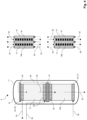
- Figure 1 shows a highly simplified schematic representation (principle sketch) of a methanol synthesis reactor 1 according to a first example of the invention.
- the methanol synthesis reactor 1 has a first process unit 13, which is designed as a reactor stage RS1.
- the methanol synthesis reactor 1 has a second process unit 14a, which is designed as a cooling stage.
- the methanol synthesis reactor 1 is on the left side of Figure 1 shown in a front view.
- Figure 1 further shows a side view of a part of the first process unit 13 top right and a side view of a part of the second process unit 14a bottom right.
- the methanol synthesis reactor 1 has a pressure jacket 11, in the interior 12 of which a first process unit 13 and a second process unit 14a are arranged.
- the first process unit 13 is arranged in an upper part of the interior 12, while the second process unit 14a is arranged in a lower part of the interior 12 and below the first process unit 13.
- Both process units 13 and 14a are fluidically connected to one another, for example via corresponding pipes of distribution and collector systems (not shown).
- the methanol synthesis reactor 1 is configured as a single-stage reactor with a reactor stage RS1 and a cooling stage.
- the reactor stage RS1 is formed by the first process unit 13, and the cooling stage by the second process unit 14a.
- Boiling boiler feedwater is used as the cooling medium stream CM1 in the first reactor stage.
- the synthesis gas stream which is also used in the reactor stage RS1 for conversion to methanol on a catalyst bed CB1, is used as the cooling medium stream CM2 in the cooling stage.
- the synthesis gas stream is preheated in the second process unit 14a and can then be introduced as a preheated synthesis gas stream into the first process unit 13 for conversion to methanol.
- the first process unit 13 is designed as a plate heat exchanger, wherein the plate heat exchanger has a plurality of flow-through (heat exchanger) plates 15, which are designed as pillow plates (pillow plate structure not shown).
- the plates are arranged vertically and are accordingly flowed through in a vertical direction.
- the plates 15 each have a flow-through plate interior 16, through which the cooling medium flow CM1 33 flows from bottom to top.
- the flow of fresh cooling medium CM1 33 enters a plate 15 from below and exits the relevant plate 15 at the top as a flow of used cooling medium CM1 34.
- the fresh cooling medium flow CM1 33 is boiling boiler feed water.
- the used cooling medium flow CM1 34 is steam.
- Two adjacent plates 15 of the first process unit 13 are spaced apart from each other to form a plate interspace 17.
- Pellets of a methanol synthesis catalyst are arranged in the plate interspaces 17, indicated by the black dots.
- the entirety of the catalyst pellets forms the catalyst bed CB1 18a.
- a preheated synthesis gas stream 29 enters the plate interspaces 17 from above and is at least partially converted in an exothermic reaction on the catalyst bed CB1 18a to a mixture of methanol and water (crude methanol).
- the plate interspaces are cooled in countercurrent by the cooling medium stream CM1 33, and the temperature in the plate interspaces is thereby controlled.
- a product stream RP1 30 is formed, which contains at least methanol, water, and unconverted synthesis gas (residual gas). This product stream RP1 30 exits the bottom of the plate interspaces 17.
- the second process unit 14a is also designed as a plate heat exchanger, wherein the plate heat exchanger has a plurality of flow-through (heat exchanger) plates 15, which are designed as pillow plates (pillow plate structure not shown).
- the plates are arranged vertically and are accordingly flowed through in a vertical direction.
- the plates 15 of the second process unit each have a flow-through plate interior 16, through which the cooling medium flow CM2 28 flows from bottom to top.
- the flow of fresh cooling medium CM2 28 enters the plate 15 from below and exits the plate 15 at the top as a flow of used cooling medium CM2 29.
- the fresh cooling medium flow CM2 28 is the synthesis gas flow.
- the used cooling medium flow CM2 29 is the preheated synthesis gas flow.
- Two adjacent plates 15 of the second process unit 14a are spaced apart from each other to form a plate interspace 17.
- no methanol synthesis catalyst is arranged in the plate interspaces 17 of the second process unit, since the second process unit serves solely to cool and, if necessary, condense the methanol-containing product stream RP1 30.
- the plate interspaces 17, through which the methanol-containing product stream RP1 30 flows from top to bottom, are cooled in countercurrent by the cooling medium stream CM2 28, whereby the initially hot methanol-containing product stream RP1 30 cools to the cold methanol-containing product stream RP1 31.
- the methanol-containing product stream RP1 31 can be obtained in merely cooled but still gaseous form, in partially condensed or fully condensed form with respect to the condensable components.
- the flow-through plates 15 with their plate interiors 16 and the plate interspaces 17 of the first and second process units 13 and 14a are arranged one behind the other in alignment with each other.
- the plates and plate spaces of the first and second process units 13 and 14a are each located one behind the other on a common longitudinal axis.
- the first process unit 13 of the methanol synthesis reactor 1 is mechanically connected to the pressure jacket 11 via a support structure 19, whereby the support structure 19 forms a mechanical connection between the first process unit and the pressure jacket 11 (the connection to the pressure jacket lies in the plane of the drawing).
- the support structure 19 is designed as a support and is arranged at least partially below the first process unit 13. In contrast to an arrangement to the side of the first process unit 13, this arrangement has the advantage that the diameter of the methanol synthesis reactor 1 is not significantly influenced, in particular, is not significantly increased.
- the support structure 19 as a support, the first process unit can expand freely upward. This applies in particular to the stack of heat exchanger plates and the components mechanically connected thereto. Components mechanically connected to the heat exchanger plates are in particular the distributor and collector systems 24, 25, and 26.
- the second process unit 14a of the methanol synthesis reactor 1 is mechanically connected to the pressure jacket 11 via a support structure 20, whereby the support structure 20 forms a mechanical connection between the second process unit and the pressure jacket 11 (the connection to the pressure jacket lies in the plane of the drawing).
- the support structure 20 is designed as a suspension and is arranged at least partially above the second process unit 14a. In contrast to an arrangement to the side of the second process unit 14a, this arrangement has the advantage that the diameter of the methanol synthesis reactor 1 is not significantly influenced, in particular, is not significantly increased.
- the support structure 20 as a suspension, the second process unit 14a can expand freely downward. This particularly applies to the stack of heat exchanger plates and the components mechanically connected thereto. Components mechanically connected to the heat exchanger plates are, in particular, the distributor and collector systems 22, 23, and 27.
- the flow pattern in the reactor 1 according to the invention is explained below.
- the synthesis gas stream 28 enters the methanol synthesis reactor 1 via a synthesis gas inlet nozzle (not shown), which extends horizontally through the pressure jacket 11.
- the synthesis gas stream 28 is then distributed to the individual plate interiors 16 of the first process unit via a distribution system 22 (simplified and shown for clarity as part of a block with the components 22, 27).
- the synthesis gas then flows from bottom to top through the plate interiors 16, cooling the product stream RP1 30 in countercurrent on the side of the plate interspaces 17.
- the synthesis gas stream 28 fulfills the function of the cooling medium stream CM2.
- the resulting preheated synthesis gas stream 29 or used cooling medium stream CM2 is combined in a collector system 23 and fed via a bypass line (indicated by the dashed line) to the top of the first process unit.
- the preheated synthesis gas stream 29 enters a distribution system 24 (simplified and shown for clarity as part of a block with components 24, 26), which distributes the synthesis gas to the plate interspaces 17 of the first process unit.
- the preheated synthesis gas reacts at the methanol synthesis catalyst of the catalyst bed to form methanol and water, thus forming the product stream RP1 30, which also includes unconverted synthesis gas (residual gas).
- the product stream RP1 30 flows from top to bottom and is withdrawn from the first process unit 13 in the bottom region, flows through an interspace area (not shown), and then enters the plate interspaces 17 of the second process unit 14a for cooling.
- the cooled product stream RP1 31 is combined with the aid of a collector system 27 (simplified and shown for clarity as part of a block with the components 22, 27) and discharged from the reactor via a product stream outlet nozzle (not shown).
- the crude product thus obtained is then subjected to further treatment (e.g., further cooling and gas-liquid separation) and processing (e.g., distillation).
- the intermediate space between the first and second process units may also comprise a corresponding collector system for the product stream RP1 in the bottom region of the first process unit 13 and a corresponding distributor system for the product stream RP1 at the top region of the second process unit 14a.
- the fresh cooling medium stream CM1 33 enters the reactor via a horizontally arranged cooling medium inlet nozzle (not shown), which extends through the pressure jacket 11, and is distributed via a distribution system 25 to the plate interiors 16 of the first process unit 13.
- the boiling boiler feedwater used for the cooling medium stream CM1 33 evaporates, thereby cooling the product stream RP1 forming in the plate interstices.
- the steam or spent cooling medium stream CM1 34 is combined in a collector system 26 (simplified and shown for reasons of clarity as part of a block with the components 24, 26) and discharged from the reactor 1 via a horizontally arranged cooling medium outlet nozzle extending through the pressure jacket.
- Figure 2 shows a highly simplified schematic representation (principle sketch) of a methanol synthesis reactor 2 according to a second example of the invention.
- the methanol synthesis reactor 2 also has a first process unit 13, which is designed as a reactor stage RS1.
- the methanol synthesis reactor 2 has a second process unit 14a, which is designed as a cooling stage.
- the methanol synthesis reactor 2 according to Figure 2 differs from the methanol synthesis reactor 1 according to Figure 1 significantly by the type of mechanical fixation of the first and second process units 13 and 14a. Otherwise, the methanol synthesis reactor 2 is also configured as a single-stage reactor with a first process unit 13 designed as a water-cooled reactor stage RS1 and a second process unit 14a designed as a gas-cooled cooling stage 14a.
- the methanol synthesis reactor 2 according to the example of Figure 2 has only one mechanical support structure 20, which mechanically connects the first process unit 13 to the pressure jacket 11.
- the support structure 20 thus forms a mechanical connection between the first process unit 13 and the pressure jacket 11 (connection to the pressure jacket lies in the plane of the drawing).
- This support structure 20 is designed as a suspension and is arranged at least partially above the first process unit 13. In contrast to an arrangement to the side of the first process unit 13, this arrangement has, as already described in relation to the example according to Figure 1 mentions the advantage that the diameter of the methanol synthesis reactor 2 is not significantly affected, in particular it is not significantly increased.
- the second process unit 14a is not mechanically connected to the pressure jacket 11 via a support structure. Rather, the first process unit 13 and the second process unit 14a are mechanically connected to one another via a connecting element 21. However, the connecting element 21 does not form a mechanical connection to the pressure jacket 11. As a result, the first process unit 13 and the second process unit 14a can expand freely downwards.
- This embodiment has the advantage, particularly with large steam quantities with respect to the cooling medium flow CM1 34, that the supply of the cooling medium flow CM1 33, in contrast to the embodiment according to Figure 1 can be made more mechanically flexible.
- Figure 3 shows a highly simplified schematic representation (principle sketch) of a methanol synthesis reactor 3 according to a third example of the invention.
- the methanol synthesis reactor 3 has a first process unit 13, which is designed as a reactor stage RS1.
- the methanol synthesis reactor 3 has a second process unit 14b, which is designed as a further or second reactor stage RS2.
- the methanol-containing product stream RP1 30 emerging from the first process unit 13 is not only cooled in the second process unit 14b, but is further converted into a methanol-containing product stream RP2 32.
- This unreacted synthesis gas or residual gas is further converted to methanol and water on the plate interspace side, i.e. within the plate interspaces 17 of the second process unit 14b, on the catalyst bed CB2 18b arranged there.
- the methanol synthesis reactor 3 is designed as a two-stage reactor, with the first reactor stage (process unit 13) being configured as a water-cooled reactor stage RS1 with boiling boiler feedwater as the cooling medium stream CM1 33 and the second reactor stage RS2 being configured as a gas-cooled reactor stage with synthesis gas as the cooling medium stream CM2 28.
- the mechanical fixation of the first and second process units 13 and 14b via the support structures 19 and 20 on the pressure jacket 11 corresponds to the mechanical fixation as for the example of the methanol synthesis reactor 1 in Figure 1 shown and described.
- Figure 4 shows a highly simplified schematic representation (principle sketch) of a methanol synthesis reactor 4 according to a fourth example of the invention.
- the methanol synthesis reactor 4 has a first process unit 13, which is designed as a reactor stage RS1.
- the methanol synthesis reactor 4 has a second process unit 14b, which is designed as a further or second reactor stage RS2.
- the methanol synthesis reactor 4 is also designed as a two-stage reactor, with the first reactor stage RS1 being configured as a water-cooled reactor stage and the second reactor stage RS2 being configured as a gas-cooled reactor stage.
- the mechanical fixing of the first and second process units 13 and 14b via the support structure 20 on the pressure jacket 11 and the connection of the first and second process units 13 and 14b via the connecting element 21 corresponds to the configuration as for the example of the methanol synthesis reactor 2 in Figure 2 shown and described.
Landscapes
- Chemical & Material Sciences (AREA)
- Organic Chemistry (AREA)
- Chemical Kinetics & Catalysis (AREA)
- Organic Low-Molecular-Weight Compounds And Preparation Thereof (AREA)
Description
- Die Erfindung betrifft einen Methanolsynthese-Reaktor, insbesondere einen Methanolsynthese-Reaktor umfassend zumindest zwei integrierte Prozesseinheiten.
- Bei nicht integrierten Lösungen zur Herstellung von kondensierbaren Reaktionsprodukten, beispielsweise Rohmethanol, finden die einzelnen Prozessschritte in separaten Einzelpositionen oder Einzelapparaten statt. Für das Beispiel der Methanolsynthese bestehen diese Prozessschritte zumindest aus der Reaktion von Synthesegas zu Methanol, der Kühlung des Reaktionsgemischs zur Kondensation von Rohmethanol, und der Trennung (Abscheidung) des kondensierten Rohmethanols vom nicht reagierten Synthese-gas (Restgas) und inerten Bestandteilen des Gasgemischs.
- Bei der Verwendung von Einzelapparaten werden Prozessmedien der Prozesseinheit durch Stutzen in einen Druckapparat und von dort aus in die jeweiligen innenliegenden Apparatebauteile eingeleitet, dort verteilt beziehungsweise gesammelt und anschließend ausgeleitet. Dies geschieht durch den jeweiligen Apparat betreffende dedizierte Apparate-Öffnungen und -Einbauten zum einen, und zum anderen durch verbindende Elemente wie Rohrleitungen und Armaturen, und je nach der relativen Lage der Prozesseinheiten über weitere Fördereinrichtungen wie Pumpen.
- Um mehrere Prozesseinheiten zu kombinieren, sind somit mehrere Druckapparate und externe Rohrleitungen erforderlich, welche separat gefertigt und auf Fundamenten oder in einem Stahlbau innerhalb einer Anlage installiert werden müssen. Dies führt zu hohen wirtschaftlichen Aufwendungen bezüglich der erforderlichen Investitionen (CAPEX) und auch der anfallenden Betriebskosten (OPEX). Dies ist insbesondere begründet durch die Vielzahl der erforderlichen Druckmäntel und Stutzen, sowie Rohrleitungen und Fördereinrichtungen. Diese Faktoren führen zu hohen Druckverlusten und Wärmeverlusten über das damit einhergehende große Gesamtvolumen und die damit einhergehende große Gesamtoberfläche, sowie zu einem höheren Energieeinsatz für die erforderlichen Fördereinrichtungen.
-
JP S60 168530 A -
US 4 743 432 A offenbart einen vertikal angeordneten Reaktor zur Erzeugung von Methanol. Dieser weist ein zylindrisches Gehäuse mit das Katalysatorbett im Inneren des Gehäuses durchsetzenden Austauscherrohren auf, sowie einen das Katalysatorbett tragenden, gasdurchlässigen Boden oder Netz im unteren Reaktorabschnitt. Unterhalb des gasdurchlässigen Bodens oder Netzes des zweituntersten und des nächsthöheren Katalysatorbetts sind in Höhe der Zu- oder Abströmöffnungen für das Gas horizontale gasundurchlässige Trennwände angeordnet. -
US 2002/048541 A1 offenbart einen Reaktor zur Durchführung einer stark exothermen katalytischen Reaktion in einem Prozessfluid, ausgerüstet mit in einem Abstand parallel zueinander angeordneter Platten, die in miteinander gegenüberliegenden seitlichen Begrenzungsflächen flache Kanäle bilden, wobei ein Teil der Kanäle einen festen Katalysator enthält und das Prozessfluid leitet und ein anderer Teil der Kanäle ein Wärmeübertragungsmedium in indirektem Wärmekontakt mit dem Prozessfluid führt. Die Platten sind eben oder mit Rillen oder Rippen versehen und die Platten auf der dem Prozessfluid zugewandten Oberfläche sind mindestens teilweise mit dem Katalysator beschichtet. -
US 5 874 051 A offenbart ein Verfahren und eine Vorrichtung zur selektiven katalytischen Oxidation von Kohlenmonoxid. Dabei wird ein Gasgemisch und ein zusätzlich zugegebenes oxidierendes Gas durch einen Reaktor geleitet, der den Katalysator enthält. Das oxidierende Gas wird an mehreren Stellen entlang des Mischgasstroms mit einem gesteuerten oder geregelten Durchflussvolumen zugegeben. Der Mischgasstrom wird durch statische Mischstrukturen im Einlassbereich des Oxidationsreaktors passiv gekühlt. - Eine Aufgabe der vorliegenden Erfindung besteht darin, die vorgenannten Nachteile des Standes der Technik zumindest teilweise zu überwinden.
- Eine weitere Aufgabe der vorliegenden Erfindung besteht darin einen Reaktor zur Synthese von Methanol bereitzustellen, welcher es ermöglicht die Zahl verbindender Rohrleitungen, einzelner Druckmäntel und Apparateböden zu reduzieren.
- Eine weitere Aufgabe der vorliegenden Erfindung besteht darin einen Reaktor zur Syntheses von Methanol bereitzustellen, welcher zumindest zwei Prozessfunktionen erfüllt und dabei ein möglichst geringes Gesamtvolumen und eine möglichst geringe Gesamtoberfläche aufweist.
- Eine weitere Aufgabe der vorliegenden Erfindung besteht darin einen Reaktor zur Synthese von Methanol bereitzustellen, welcher in Bezug auf die Erfüllung von zumindest zwei Prozessfunktionen eine möglichst geringe Gesamtfertigungszeit erfordert.
- Eine weitere Aufgabe der vorliegenden Erfindung besteht darin einen Reaktor zur Synthese von Methanol bereitzustellen, welcher möglichst keine oder wenige Fördereinrichtungen in Bezug auf die zu erfüllenden Prozessfunktionen erfordert.
- Eine weitere Aufgabe der vorliegenden Erfindung besteht darin einen Reaktor zur Synthese von Methanol bereitzustellen, welcher so konstruiert ist, dass Materialspannungen in den metallbasierten Bauteilen minimiert werden.
- Ein Beitrag zur mindestens teilweisen Erfüllung mindestens einer der obigen Aufgaben wird durch die unabhängigen Ansprüche geleistet. Die abhängigen Ansprüche stellen bevorzugte Ausführungsformen bereit, die zur mindestens teilweisen Erfüllung mindestens einer der Aufgaben beitragen. Bevorzugte Ausgestaltungen von Bestandteilen einer erfindungsgemäßen Kategorie sind, soweit zutreffend, ebenso bevorzugt für gleichnamige oder entsprechende Bestandteile einer jeweils anderen erfindungsgemäßen Kategorie.
- Die Ausdrücke "aufweisend", "umfassend" oder "beinhaltend" etc. schließen nicht aus, dass weitere Elemente, Inhaltsstoffe etc. enthalten sein können. Der unbestimmte Artikel "ein" schließt nicht aus, dass eine Mehrzahl vorhanden sein kann.
- Gemäß einem ersten Aspekt der Erfindung wird ein Methanolsynthese-Reaktor zur Herstellung von Methanol aus einem Synthesegasgemisch vorgeschlagen, aufweisend
- (a) einen Druckmantel mit einem Innenraum, wobei in dem Innenraum zumindest zwei fluidisch miteinander verbundene Prozesseinheiten übereinander angeordnet sind;
- (b) eine erste Prozesseinheit, wobei die erste Prozesseinheit als Reaktorstufe RS1 zur Synthese von Methanol aus einem Synthesegas-Strom an einem Katalysatorbett CB1 konfiguriert ist, wodurch ein methanolhaltiger Produktstrom RP1 erzeugbar ist, und
- die erste Prozesseinheit als Plattenwärmeübertrager ausgestaltet ist, wobei die erste Prozesseinheit dabei eine Vielzahl von vertikal und parallel zueinander angeordneten Platten mit durchströmbaren Platteninnenräumen aufweist, und zwischen benachbarten Platten Plattenzwischenräume ausgebildet sind, wobei
- in den Plattenzwischenräumen ein fester Methanolsynthese-Katalysator angeordnet ist, welcher das Katalysatorbett CB1 bildet, und die erste Prozesseinheit so konfiguriert ist, dass die Plattenzwischenräume von dem Synthesegas-Strom und von dem methanolhaltigen Produktstrom RP1 von oben nach unten durchströmbar sind und die Platteninnenräume von einem ersten Kühlmedien-Strom CM1 von unten nach oben durchströmbar sind, wodurch
- der methanolhaltige Produktstrom RP1 durch den ersten Kühlmedien-Strom CM1 im Gegenstrom kühlbar ist, und wobei
- die erste Prozesseinheit Mittel zum Abziehen des methanolhaltigen Produktstroms RP1 aus der ersten Prozesseinheit aufweist;
- (c) eine unterhalb der ersten Prozesseinheit angeordnete zweite Prozesseinheit, wobei
- die zweite Prozesseinheit als Plattenwärmeübertrager ausgestaltet ist, wobei die zweite Prozesseinheit dabei eine Vielzahl von vertikal und parallel zueinander angeordneten Platten mit durchströmbaren Platteninnenräumen aufweist, und zwischen benachbarten Platten Plattenzwischenräume ausgebildet sind, wobei
- die zweite Prozesseinheit so konfiguriert ist, dass die Platteninnenräume von einem zweiten Kühlmedien-Strom CM2 von unten nach oben durchströmbar sind, und wobei
- (c1) die zweite Prozesseinheit als Kühlstufe ausgestaltet ist und dabei so konfiguriert ist, dass die Plattenzwischenräume von dem methanolhaltigen Produktstrom RP1 von oben nach unten durchströmbar sind, wodurch der methanolhaltige Produktstrom RP1 durch den zweiten Kühlmedien-Strom CM2 im Gegenstrom kühlbar ist, oder
- (c2) die zweite Prozesseinheit als Reaktorstufe RS2 ausgestaltet ist und dabei zur Synthese von Methanol aus dem aus der ersten Prozesseinheit abziehbaren methanolhaltigen Produktstrom RP1 an einem Katalysatorbett CB2 konfiguriert ist, wodurch ein methanolhaltiger Produktstrom RP2 erzeugbar ist, und wobei in den Plattenzwischenräumen ein fester Methanolsynthese-Katalysator angeordnet ist, welcher das Katalysatorbett CB2 bildet, und die zweite Prozesseinheit so konfiguriert ist, dass die Plattenzwischenräume von dem methanolhaltigen Produktstrom RP1 und dem methanolhaltigen Produktstrom RP2 von oben nach unten durchströmbar sind, wodurch der methanolhaltige Produktstrom RP2 durch den zweiten Kühlmedien-Strom CM2 im Gegenstrom kühlbar ist.
- Unter einer "Vielzahl" von Platten wird erfindungsgemäß eine Mehrzahl von Platten verstanden, vorzugsweise jedoch mehr als zwei Platten, insbesondere mindestens 5 Platten, oder mindestens 10 Platten, oder mindestens 25 Platten, oder mindestens 50 Platten.
- Die zumindest zwei Prozesseinheiten im Innenraum des Druckmantels beinhalten die erste und die zweite Prozesseinheit.
- Erfindungsgemäß werden zumindest zwei Prozesseinheiten in einen gemeinsamen Druckmantel integriert. Unter einem Druckmantel wird dabei eine umhüllende Struktur verstanden, welche höheren Innendrücken standhält, insbesondere Innendrücken deutlich oberhalb des Atmosphärendrucks, beispielsweise Drücken von mehr als 5 bar.
- Die erste Prozesseinheit erfüllt die Funktion einer Reaktorstufe zur Synthese von Methanol aus einem in die Reaktorstufe einleitbaren Synthesegas-Strom, hier als Reaktorstufe RS1 bezeichnet. Zur Erfüllung dieser Funktion ist die erste Prozesseinheit als Plattenwärmeübertrager ausgestaltet. Mit anderen Worten, die erste Prozesseinheit weist eine Struktur eines Plattenwärmeübertragers auf.
- Dabei sind zwei benachbarte Platten des Plattenwärmeübertragers so voneinander beabstandet, dass sich zwischen zwei benachbarten Platten ein Plattenzwischenraum ausbildet.
- In den Plattenzwischenräumen der ersten Prozesseinheit ist ein fester Methanolsynthese-Katalysator angeordnet. Dabei bildet die Gesamtheit des in den Plattenzwischenräumen der ersten Prozesseinheit angeordneten Methanolsynthese-Katalysators das Katalysatorbett, hier als Katalysatorbett CB1 bezeichnet.
- Bei dem Methanolsynthese-Katalysator handelt es sich um einen dem Fachmann bekannten Methanolsynthese-Katalysator, beispielsweise auf Kupfer-Basis. Der Methanolsynthese-Katalysator kann dabei beispielsweise als Schüttung oder strukturierte Packung ausgestaltet sein.
- Die Methanolsynthese-Katalysator aufweisenden Plattenzwischenräume sind so konfiguriert, dass sie mit dem Synthesegas-Strom und dem Produktstrom RP1 von oben nach unten durchströmbar sind.
- Alternativ formuliert weist die erste Prozesseinheit Mittel auf welche so konfiguriert sind, dass die Plattenzwischenräume mit dem Synthesegas-Strom und dem Produktstrom RP1 von oben nach unten durchströmbar sind.
- Dadurch findet eine exotherme Reaktion des Synthesegases des Synthesegas-Stroms am Methanolsynthese-Katalysator des Katalysatorbetts CB1 statt. Dabei bildet sich der Produktstrom RP1. Entsprechend sind die Plattenzwischenräume auch mit dem Produktstrom RP1 von oben nach unten durchströmbar.
- Dabei wird insbesondere der methanolhaltige Produkstrom RP1 durch den die Platteninnenräume von unten nach oben durchströmenden ersten Kühlmedien-Strom CM1 im Gegenstrom gekühlt.
- Das Synthesegas des Synthesegas-Stroms weist ein Kohlenstoffoxid, also Kohlenmonoxid oder Kohlendioxid, oder eine Mischung daraus auf. Ferner weist das Synthesegas des Synthesegas-Stroms Wasserstoff auf. Das Synthesegas kann darüber hinaus generell inerte oder unter den Bedingungen der Methanolsynthesese inerte Bestandteile aufweisen. Beispiele sind Stickstoff oder Methan. Der Produktstrom RP1 weist zumindest Methanol und Wasser als kondensierbare Bestandteile sowie gegebenenfalls nicht erwünschte kondensierbare und nicht kondensierbare Nebenprodukte auf. Ferner weist der Produktstrom RP1 gegebenenfalls nicht umgesetztes Synthesegas auf.
- Die Platten der ersten Prozesseinheit weisen durchströmbare Innenräume auf. Dabei sind die Innenräume der Platten von einem ersten Kühlmedien-Strom CM1 durchströmbar. Dabei ist die erste Prozesseinheit so konfiguriert, dass die Platteninnenräume von dem ersten Kühlmedien-Strom CM1 von unten nach oben durchströmbar sind.
- Alternativ formuliert weist die erste Prozesseinheit Mittel auf welche so konfiguriert sind, dass die Platteninnenräume von dem Kühlmedien-Strom CM1 von unten nach oben durchströmbar sind.
- Die Platteninnenräume der ersten Prozesseinheit sind dabei vorzugsweise in vertikaler Richtung durchströmbar, insbesondere in vertikaler Richtung von unten nach oben von dem ersten Kühlmedien-Strom durchströmbar.
- Die Plattenzwischenräume der ersten Prozesseinheit sind dabei vorzugsweise in vertikaler Richtung durchströmbar, insbesondere in vertikaler Richtung von oben nach unten von dem Synthesegasstrom und dem Produktstrom RP1 durchströmbar.
- Die zweite Prozesseinheit erfüllt entweder die Funktion einer Kühlstufe oder die Funktion einer zweiten Reaktorstufe RS2.
- Aus der ersten Prozesseinheit, welche als Reaktorstufe RS1 konfiguriert ist, ist der methanolhaltige Produktstrom RP1 abziehbar und in die zweite Prozesseinheit einleitbar. In der zweiten Prozesseinheit wird dieser Produktstrom RP1 entweder gekühlt (Alternative c1) oder weiter zu einem methanolhaltigen Produktstrom RP2 umgesetzt (Alternative c2). In letzterem Fall wird im methanolhaltigen Produktstrom RP1 nicht umgesetztes Synthesegas, also verbliebenes Synthesegas oder Restgas, zu Methanol umgesetzt.
- Zur Erfüllung dieser alternativen Funktionen ist auch die zweite Prozesseinheit als Plattenwärmeübertrager ausgestaltet. Mit anderen Worten, die zweite Prozesseinheit weist eine Struktur eines Plattenwärmeübertragers auf.
- Dabei sind zwei benachbarte Platten des Plattenwärmeübertragers so voneinander beabstandet, dass sich zwischen zwei benachbarten Platten ein Plattenzwischenraum ausbildet.
- Die Platten weisen durchströmbare Innenräume auf, welche von einem zweiten Kühlmedien-Strom CM2 durchströmt werden. Dabei ist die zweite Prozesseinheit so konfiguriert, dass die Platteninnenräume von dem zweiten Kühlmedienstrom CM2 von unten nach oben durchströmbar sind.
- Alternativ formuliert weist die erste Prozesseinheit Mittel auf welche so konfiguriert sind, dass die Platteninnenräume von dem zweiten Kühlmedien-Strom CM2 von unten nach oben durchströmbar sind.
- Die Platteninnenräume der zweiten Prozesseinheit sind dabei vorzugsweise in vertikaler Richtung von dem zweiten Kühlmedien-Strom CM2 durchströmbar, insbesondere in vertikaler Richtung von unten nach oben von dem zweiten Kühlmedien-Strom durchströmbar.
- Entsprechend Alternative c1 ist die zweite Prozesseinheit als Kühlstufe ausgestaltet. Entsprechend dieser Konfiguration sind die Plattenzwischenräume der zweiten Prozesseinheit von dem methanolhaltigen Produktstrom RP1 von oben nach unten durchströmbar. Alternativ formuliert weist die zweite Prozesseinheit entsprechend Alternative c1 Mittel auf welche so konfiguriert sind, dass die Plattenzwischenräume von dem methanolhaltigen Produktstrom RP1 von oben nach unten durchströmbar sind. Die Plattenzwischenräume sind dabei vorzugsweise in vertikaler Richtung von dem methanolhaltigen Produktstrom RP1 durchströmbar.
- Dabei wird der methanolhaltige Produkstrom RP1 durch den die Platteninnenräume von unten nach oben durchströmenden zweiten Kühlmedien-Strom CM2 gekühlt. Insbesondere ist die zweite Prozesseinheit gemäß Alternative c1 dabei so konfiguriert, dass der methanolhaltige Produktstrom RP1 so weit gekühlt wird, dass eine Kondensation von Methanol und Wasser aus dem methanolhaltigen Produktstrom RP1 erfolgt.
- Entsprechend Alternative c2 ist die zweite Prozesseinheit als Reaktorstufe RS2 ausgestaltet.
- Entsprechend dieser Konfiguration c2 ist in den Plattenzwischenräumen der zweiten Prozesseinheit ein fester Methanolsynthese-Katalysator angeordnet. Dabei bildet die Gesamtheit des in den Plattenzwischenräumen der zweiten Prozesseinheit angeordneten Methanolsynthese-Katalysators das Katalysatorbett, hier als Katalysatorbett CB2 bezeichnet.
- Bei dem Methanolsynthese-Katalysator handelt es sich um einen dem Fachmann bekannten Methanolsynthese-Katalysator, beispielsweise auf Kupfer-Basis. Der Methanolsynthese-Katalysator kann dabei beispielsweise als Schüttung oder strukturierte Packung ausgestaltet sein.
- Die Methanolsynthese-Katalysator aufweisenden Plattenzwischenräume sind so konfiguriert, dass sie mit dem Produktstrom RP1 und dem Produktstrom RP2 von oben nach unten durchströmbar sind. Alternativ formuliert weist die die zweite Prozesseinheit Mittel auf welche so konfiguriert sind, dass die Plattenzwischenräume mit dem Produktstrom RP1 und dem Produktstrom RP2 von oben nach unten durchströmbar sind. Dadurch findet eine exotherme Reaktion des Produktstroms RP1 am Methanolsynthese-Katalysator des Katalysatorbettes CB2 statt. Dabei bildet sich der Produktstrom RP2. Entsprechend sind die Plattenzwischenräume auch mit dem Produktstrom RP2 von oben nach unten durchströmbar. Die zweite Prozesseinheit bildet in diesem Fall eine zweite Reaktorstufe RS2. In dieser zweiten Reaktorstufe RS2 wird im Produktstrom RP1 enthaltenes Synthesegas zu Methanol umgesetzt, welches in der ersten Reaktorstufe RS1 aufgrund der Ausbildung des für die Methanolsynthese typischen thermodynamischen Gleichgewichts nicht zu Methanol umgesetzt werden konnte. Dieses verbleibende Synthesegas oder Restgas bildet also einen Teil des Produktstroms RP1.
- Der Produktstrom RP2 weist zumindest Methanol und Wasser als kondensierbare Bestandteile sowie gegebenenfalls nicht erwünschte kondensierbare und nicht kondensierbare Nebenprodukte auf. Ferner weist der Produktstrom RP2 gegebenenfalls nach wie vor nicht umgesetztes Synthesegas auf.
- Entsprechend der Konfiguration gemäß Alternative c2 sind die Plattenzwischenräume der zweiten Prozesseinheit von dem methanolhaltigen Produktstrom RP1 und methanolhaltigen Produktstrom RP2 von oben nach unten durchströmbar. Alternativ formuliert weist die zweite Prozesseinheit entsprechend Alternative c2 Mittel auf welche so konfiguriert sind, dass die Plattenzwischenräume von dem methanolhaltigen Produktstrom RP1 und dem methanolhaltigen Produktstrom RP2 von oben nach unten durchströmbar sind. Die Plattenzwischenräume sind dabei vorzugsweise in vertikaler Richtung von dem methanolhaltigen Produktstrom RP1 und dem methanolhaltigen Produktstrom RP2 durchströmbar.
- Dabei wird der methanolhaltige Produkstrom RP2 durch den die Platteninnenräume von unten nach oben durchströmenden zweiten Kühlmedien-Strom CM2 im Gegenstrom gekühlt.
- Die erste und zweite Prozesseinheit sind innerhalb des Druckmantels übereinander angeordnet, wobei die zweite Prozesseinheit unterhalb der ersten Prozesseinheit angeordnet ist. Beide Prozesseinheiten sind fluidisch miteinander verbunden. Insbesondere sind die erste und zweite Prozesseinheit bezüglich des Synthesegas-Stroms sowie der methanolhaltigen Produktströme RP1 und RP2 fluidisch miteinander verbunden, insbesondere auf der Seite der Plattenzwischenräume fluidisch miteinander verbunden.
- Vorzugsweise sind die erste und zweite Prozesseinheit fluchtend hintereinander, das heißt entlang einer bezüglich der ersten und zweiten Prozesseinheit gemeinsamen Geraden oder Achse, angeordnet. Vorzugsweise ist die zweite Prozesseinheit also gegenüber der ersten Prozesseinheit nicht versetzt angeordnet und umgekehrt.
- Der Methanolsynthese-Reaktor ist gemäß einer Ausführungsform als einstufiger Reaktor mit einer Reaktorstufe RS1 oben und einer Kühlstufe unten ausgestaltet. Gemäß einer weiteren Ausführungsform ist der Methanolsynthese-Reaktor als zweistufiger Reaktor mit einer ersten Reaktorstufe RS1 oben und einer zweiten Reaktorstufe RS2 unten ausgestaltet.
- Der Methanolsynthese-Reaktor kann darüber hinaus weitere Prozesseinheiten beinhalten. Beispielsweise kann der Methanolsynthese-Reaktor gemäß Alternative c1 unterhalb der zweiten Prozesseinheit eine dritte Prozesseinheit aufweisen, welche als Kondensator ausgestaltet ist. Gemäß einem weiteren Beispiel kann der Methanolsynthese-Reaktor gemäß Alternative c1 unterhalb der dritten Prozesseinheit eine vierte Prozesseinheit aufweisen, welche als Gas-Flüssigkeit-Separator ausgestaltet ist. Gemäß einem weiteren Beispiel kann der Methanolsynthese-Reaktor gemäß Alternative c2 unterhalb der zweiten Prozesseinheit eine dritte Prozesseinheit aufweisen, welche als Kühlstufe ausgestaltet ist. Gemäß einem weiteren Beispiel kann der Methanolsynthese-Reaktor gemäß Alternative c2 unterhalb der dritten Prozesseinheit eine vierte Prozesseinheit aufweisen, welche als Kondensator ausgestaltet ist. Gemäß einem weiteren Beispiel kann der Methanolsynthese-Reaktor gemäß Alternative c2 unterhalb der vierten Prozesseinheit eine fünfte Prozesseinheit aufweisen, welche als Gas-Flüssigkeit-Separator ausgestaltet ist. Auch sind Ausführungsformen denkbar, in denen die Kühlstufe bereits als Kondensator ausgestaltet ist, so dass in der Kühlstufe bereits eine vollständige Kondensation kondensierbarer Produkte und Nebenprodukte erfolgt.
- Bei dem Kühlmedium für den ersten Kühlmedienstrom CM1 und/oder zweiten Kühlmedienstrom CM2 kann es sich um jedes beliebige geeignete gasförmige oder flüssige Kühlmedium handeln.
- Vorzugsweise handelt es sich bei dem Kühlmedium für die erste Prozesseinheit um siedendes Wasser, insbesondere siedendes Kesselspeisewasser. Eine bevorzugte Ausführungsform des Reaktors ist daher dadurch gekennzeichnet, dass der erste Kühlmedien-Strom CM1 siedendes Kesselspeisewasser umfasst. Insbesondere ist der erste Kühlmedien-Strom CM1 beim Durchströmen der Platteninnenräume der ersten Prozesseinheit verdampfbar.
- Die erste Prozesseinheit ist in diesem Fall als wassergekühlte Reaktorstufe RS1 ausgestaltet, erfüllt also die Funktion einer wassergekühlten Reaktorstufe. Das Kühlmedium verdampft insbesondere durch die bei der Bildung des methanolhaltigen Produktstroms RP1 aufgenommene thermische Energie. Die zur Verdampfung erforderliche thermische Energie entspricht dabei der Verdampfungsenthalpie des Kühlmediums.
- Vorzugsweise handelt es sich beim Kühlmedium für die zweite Prozesseinheit um ein gasförmiges Kühlmedium. Die zweite Prozesseinheit ist gemäß dieser Ausführungsform entweder als gasgekühlte Kühlstufe entsprechend Alternative c1 oder als gasgekühlte Reaktorstufe RS2 entsprechend Alternative c2 ausgestaltet. In letzterem Fall erfüllt die zweite Prozesseinheit die Funktion einer gasgekühlten Reaktorstufe.
-
Figur 5 zeigt ein messtechnisch und durch eine Simulation ermitteltes typisches Temperaturprofil eines Katalysatorbetts über die Länge eines Methanol-Reaktors. Dieses Temperaturprofil kann räumlich vom Eintritt in den Reaktor in Richtung Austritt in vier Teile unterteilt werden, wie nachsehend erläutert. - Ein erster Teil des Katalysatorbetts dient der Erwärmung des Synthesegases, wobei Wärme vom Kühlmittel auf das Synthesegas und den Katalysator übertragen wird. In Zuge dessen beginnt allmählich die Reaktion zur Methanolbildung, bei der aufgrund des exothermen Charakters der Reaktion Wärme erzeugt und die Temperatur sowohl des Katalysators als auch des Gasgemisches (Synthesegas und gasförmiges Methanol/Wasser, sowie nicht-reagiertes Synthesegas) erhöht wird. Im weiteren Verlauf der Reaktion entspricht die Temperatur des Katalysatorbetts und des Gasgemischs in etwa der Temperatur des Kühlmittels.
- In einem zweiten Teil des Katalysatorbetts schreitet die Reaktion weiter fort, wobei weiter Wärme erzeugt und das Katalysatorbett und das Gasgemisch weiter erwärmt werden. Die Geschwindigkeit der Wärmeerzeugung in diesem zweiten Teil des Katalysatorbettes ist schneller als die Wärmeübertragung vom Kühlmittel, so dass die Temperaturen des Gasgemischs und des Katalysatorbetts über die Temperatur des Kühlmittels steigen. Dabei erwärmt die bei der Reaktion erzeugte Wärme zunächst den festen Katalysator. Anschließend erfolgt Wärmeübertragung vom Katalysator auf das Prozessgasgemisch, um den Katalysator zu kühlen. Anschließend überträgt das Prozessgasgemisch die Wärme auf das im Reaktor verwendete Kühlmittel. Eine weitere Art der Wärmeübertragung ist Wärmekonvektion vom festen Katalysator auf die Reaktoreinbauten. Die Temperatur steigt in diesem Teil des Katalysatorbetts weiter über die des Kühlmittels. Im Verlauf der Reaktion werden die Edukte des Prozessgasgemischs (Kohlenoxide und Wasserstoff) weiter verbraucht und mehr und mehr Rohmethanol als Teil des Prozessgasgemischs wird erzeugt. Da es sich bei der katalytischen Methanolsynthese um eine Gleichgewichtsreaktion handelt, nähert sich die Reaktionsgeschwindigkeit und damit auch die Wärmeproduktionsrate bei Erreichen der Gleichgewichtskonzentration von Edukten und Produkten einem Grenzwert.
- In einem dritten Teil des Katalysatorbetts verlangsamt sich die Geschwindigkeit der Wärmeproduktion, da sich die Reaktion den Gleichgewichtsbedingungen nähert. Die Wärmeübertragung vom Katalysator auf das Prozessgasgemisch und letztlich auf das Kühlsystem setzt sich dennoch fort und ermöglicht es, die Temperatur des Katalysatorbetts wieder zu senken.
- In einem letzten, vierten Teil des Katalysatorbetts befindet sich die Reaktion im Gleichgewicht, ohne dass eine nennenswerte Wärmeproduktion stattfindet. In diesem Teil des Katalysatorbetts sinkt die Temperatur weiter in Richtung der Kühlmitteltemperatur.
- Bezüglich der ersten als auch der zweiten Prozesseinheit gilt, dass die Platten vertikal angeordnet sind und die reagierenden oder zu kühlenden Prozessgase innerhalb der Plattenzwischenräume von oben nach unten geführt werden. Gemäß des oben näher erläuterten Temperaturprofils wird die Temperatur auf der Plattenzwischenraumseite von oben nach unten somit im weitesten Sinne fallen, es bildet sich also über den längsten Bereich der Prozesseinheit ein Temperaturgradient mit fallender Temperatur von oben nach unten aus. Dies gilt prinzipiell noch eindeutiger, wenn die Plattenzwischenräume der zweiten Prozesseinheit wie im Falle der Alternative c1 nicht mit Katalysator gefüllt sind. In diesem Fall fällt die Temperatur des Produktstroms RP1 in der zweiten Prozesseinheit mit fortschreitender Kühlung von oben nach unten über die gesamte Länge der Prozesseinheit kontinuierlich ab.
- Da die Dichte eines Mediums bei höheren Temperaturen relativ gesehen niedriger ist als die Dichte des gleichen Mediums bei niedrigeren Temperaturen, bildet sich im Betrieb des Reaktors auch ein Dichtegradient mit einer niedrigen Dichte in einer oberen Zone des Reaktors oder einer Prozesseinheit hin zu einer höheren Dichte in einer unteren Zone des Reaktors oder einer Prozesseinheit aus. Die beabsichtigte Strömungsrichtung des jeweiligen Prozessgasgemischs auf der Plattenzwischenraumseite von oben nach unten wird dadurch unterstützt, da sich schwerere Komponenten (Komponenten mit höherer Dichte) durch die Wirkung der Gravitation in einem unteren Bereich des Reaktors oder einer Prozesseinheit sammeln. Schließlich wird die beabsichtigte Strömungsrichtung des jeweiligen Gemischs weiterhin auch durch die vertikale Anordnung der Platten der Prozesseinheiten begünstigt.
- Die Vorteile des erfindungsgemäßen Reaktors erstrecken sich weiterhin auf die Führung der jeweiligen Kühlmedien. Erfindungsgemäß werden die Kühlmedien auf der Platteninnenraumseite der durchströmbaren Platten von unten nach oben geführt, während das jeweilig zu kühlende Prozessgasgemisch auf der Plattenzwischenraumseite von oben nach unten geführt wird. Das Kühlmedium tritt also in einem unteren Bereich in die jeweilige Prozesseinheit ein, und tritt in einem oberen Bereich aus dieser aus. Dabei wärmt es sich in Strömungsrichtung von unten nach oben kontinuierlich durch die Abkühlung des Prozessgasgemisches auf und/oder geht kontinuierlich von einer flüssigen Phase in eine gasförmige Phase über. Der vorgenannte Temperaturgradient und/oder Dichtegradient bildet sich somit nicht nur auf der Platteninnenraumseite, sondern auch auf der Plattenzwischenraumseite aus.
- Vereinfacht lässt sich daraus ableiten, dass die jeweilige Prozesseinheit in ihrem Kopfbereich am heißesten ist und im Sumpfbereich am kältesten. Weiterhin weisen die Medien der jeweiligen Prozesseinheit im Kopfbereich im Wesentlichen die niedrigste Dichte auf und im Sumpfbereich die höchste Dichte. Für die Alternative c1 gilt dies im Prinzip für den gesamten Reaktor, da die zweite Prozesseinheit lediglich der Kühlung dient. Je nach Auslegung der Kühlstufe gemäß Alternative c2 neigt das sich auf der Plattenzwischenraumseite befindende Gemisch außerdem mehr oder weniger stark zur Kondensation.
- Durch die Kombination der vorgenannten Effekte ist es in Bezug auf den erfindungsgemäßen Reaktor möglich, sowohl bezüglich der Prozessgasgemische auf der Plattenzwischenraumseite (Synthesegas-Strom und Produktströme RP1 und RP2) als auch bezüglich der Kühlmedien auf der Platteninnenraumseite, vollständig auf Fördereinrichtungen mit erzwungener Strömung, wie beispielsweise Pumpen, zu verzichten.
- Handelt es sich bei dem Kühlmedium der ersten Prozesseinheit um siedendes Wasser, insbesondere siedendes Kesselspeisewasser, dann entspricht die zur Verdampfung erforderliche thermische Energie der Verdampfungsenthalpie des Kühlmediums. Da die Vorrichtung aufgrund der vorgenannten Effekte in einer oberen Zone im Betrieb heiß ist, wird die Verdampfung in der oberen Zone begünstigt. Dabei bildet sich, wie oben erläutert, auf der Platteninnenraumseite der ersten Prozesseinheit ein Dichtegradient mit einer niedrigen Dichte in der oberen Zone und hoher Dichte in der unteren Zone aus. Dies führt zum sogenannten Thermosyphon-Effekt, welcher einen Naturumlauf des Kühlmediums ermöglicht, ohne dass wie oben beschrieben eine Fördereinrichtung mit erzwungener Strömung erforderlich wäre.
- In vorteilhafter Weise, durch die Ausbildung vorgenannter Temperatur- und Dichtegradienten, wird also das sich erhitzende Kühlmedium innerhalb der Platteninnenräume der ersten und/oder zweiten Prozesseinheit nach oben "gesaugt", während das sich abkühlende und/oder kondensierende Prozessgasgemisch auf der Seite der Plattenzwischenräume der ersten und/oder zweiten Prozesseinheit nach unten "fällt".
- Der sich durch die erfindungsgemäße Anordnung der ersten und zweiten Prozesseinheit und die erfindungsgemäße Strömungsführung im Betrieb ausbildende Temperaturgradient findet sich nicht nur in den strömenden Medien, sondern entsprechend auch in den metallischen Strukturen der Vorrichtung wieder, da sich die Wärme der Medien entsprechend auf die metallischen Strukturen überträgt. Da der Temperaturgradient kontinuierlich fallend von einem oberen Bereich zu einem unteren Bereich auch in den metallischen Strukturen der Vorrichtung verläuft und im Wesentlichen keine Temperaturspitzen aufweist, werden mögliche thermische Spannungen aufgrund lokal auftretender großer Temperaturunterschiede auf ein Minimum reduziert. Die erste und zweite Prozesseinheit sowie der Druckmantel sind insbesondere aus einem Metall oder einer Metall-Legierung gefertigt. Vorzugsweise sind zumindest die medienführenden Komponenten der ersten und zweiten Prozesseinheit und des Druckmantels aus einem Metall oder einer Metall-Legierung gefertigt.
- Eine Ausführungsform des erfindungsgemäßen Reaktors ist dadurch gekennzeichnet, dass die Platten der ersten Prozesseinheit und/oder die Platten der zweiten Prozesseinheit als Kissenplatten ausgestaltet sind.
- Kissenplatten anstatt konventioneller Wärmeübertrager-Platten mit gerader Form bieten insbesondere bezüglich der erfindungsgemäßen Vorrichtung Vorteile in Bezug auf mechanische Stabilität und der Effizienz der Wärmeübertragung. Eine Verbesserung der Effizienz der Wärmeübertragung gegenüber konventionellen Platten ergibt sich insbesondere in Bezug auf die Erzeugung von Dampf auf den Platteninnenseiten bei Erreichen des Nukleationspunktes und der nachfolgenden daraus resultierenden Dampfblasenbildung. Kissenplatten-Wärmeübertrager sind beispielsweise näher in der
DE 10 2016 005 999 A1 beschrieben. - Eine Ausführungsform des erfindungsgemäßen Reaktors ist dadurch gekennzeichnet, dass die zweite Prozesseinheit so konfiguriert ist, dass die Platteninnenräume von dem Synthesegas-Strom durchströmbar sind, wobei der Synthesegas-Strom die Funktion des zweiten Kühlmedien-Stroms CM2 erfüllt, wodurch ein vorgewärmter Synthesegas-Strom erzeugbar ist.
- Um den Einsatz von Kühlmittel zu minimieren, wird der für die Methanolsynthese vorgesehene Synthesegas-Strom in vorteilhafter Weise als Kühlmittel CM2 in der zweiten Prozesseinheit verwendet. In diesem Fall erfüllt die zweite Prozesseinheit entweder die Funktion einer gasgekühlten Kühlstufe (Alternative c1) oder die Funktion einer gasgekühlten Reaktorstufe (Alternative c2). Dabei wird der Synthesegas-Strom in vorteilhafter Weise vorgewärmt, wodurch die Wärmeintegration des erfindungsgemäßen Reaktors verbessert wird. Nach Einleiten des vorgewärmten Synthesegas-Stroms auf die Plattenzwischenraumseite der ersten Prozesseinheit zur Erzeugung des methanolhaltigen Produktstroms RP1 wird die für die Umsetzung am Katalysator erforderliche Temperatur schneller erreicht. Zusätzlich kann auf eine externe Vorrichtung zur Vorwärmung des Synthesegas-Stroms, beispielsweise auf einen Vorwärmer, verzichtet werden.
- Eine Ausführungsform des erfindungsgemäßen Reaktors ist daher dadurch gekennzeichnet, dass der Methanolsynthese-Reaktor Mittel zum Ausleiten des vorgewärmten Synthesegas-Stroms aus der zweiten Prozesseinheit aufweist, sowie Mittel zum Einleiten des vorgewärmten Synthesegasstroms in die erste Prozesseinheit zum Erzeugen des methanolhaltigen Produktstroms RP1 aufweist.
- Eine Ausführungsform des erfindungsgemäßen Reaktors ist dadurch gekennzeichnet, dass die Platteninnenräume der ersten Prozesseinheit und die Platteninnenräume der zweiten Prozesseinheit zumindest teilweise fluchtend hintereinander angeordnet sind und/oder die Plattenzwischenräume der ersten Prozesseinheit und die Plattenzwischenräume der zweiten Prozesseinheit zumindest teilweise fluchtend hintereinander angeordnet sind.
- Unter einer fluchtenden Anordnung hintereinander ist dabei zu verstehen, dass zwei in Flussrichtung der Prozessmedien (Synthesegas-Strom, methanolhaltiger Produktstrom RP1, methanolhaltiger Produktstrom RP2) hintereinander angeordnete Platten der ersten und zweiten Prozesseinheit in Bezug auf die Längsachsen ihrer Platteninnenräume oder Plattenzwischenräume entlang dieser Längsachsen angeordnet sind.
- Insbesondere erfolgt diese Anordnung, ohne dass die jeweilige Platte der ersten Prozesseinheit in Bezug auf die betreffende Längsachse versetzt zur Platte der zweiten Prozesseinheit angeordnet ist.
- Weiter bevorzugt sind die beiden hintereinander angeordneten Platten der ersten und zweiten Prozesseinheit dabei so angeordnet, dass diese bei gleichen Querschnittsflächen in Bezug auf diese Querschnittsflächen kongruent angeordnet sind, das heißt dass ihre beiden Querschnittsflächen deckungsgleich sind, wenn diese entlang der Längsachse verschoben und zur Deckung gebracht würden.
- Vorzugsweise ist der Reaktor dabei so ausgestaltet, dass die fluchtende Anordnung für alle Platten der ersten Prozesseinheit im Verhältnis zu allen Platten der zweiten Prozesseinheit gilt. Das heißt jede Platte der ersten Prozesseinheit hat eine fluchtend hintereinander zu ihr angeordnete Platte als Gegenstück in der zweiten Prozesseinheit.
- Durch die Maßnahme der fluchtenden Anordnung kann das Volumen des erfindungsgemäßen Reaktors minimiert werden. Mit anderen Worten, das Verhältnis des beanspruchten Volumens zur zur Verfügung gestellten nutzbaren Fläche wird minimiert. Unter der nutzbaren Fläche wird dabei diejenige Fläche verstanden, welche zur Kühlung der Prozessmedien durch die Kühlmedien oder zur Synthese von Methanol aus den Prozessmedien genutzt werden kann.
- Eine Ausführungsform des erfindungsgemäßen Reaktors ist dadurch gekennzeichnet, dass der Methanolsynthese-Reaktor eine Stützstruktur aufweist, wobei die Stützstruktur als zumindest teilweise unterhalb einer Prozesseinheit angeordnete Abstützung und/oder als zumindest teilweise oberhalb einer Prozesseinheit angeordnete Aufhängung ausgestaltet ist und dabei eine mechanische Verbindung zwischen einer Prozesseinheit und dem Druckmantel ausbildet.
- Eine "Stützstruktur" im Sinne der Erfindung kann alternativ auch als "Stützelement" bezeichnet werden.
- Der erfindungsgemäße Reaktor weist vorzugsweise zumindest eine Stützstruktur auf. Die Stützstruktur bildet eine mechanische Verbindung zwischen einer Prozesseinheit und dem Druckmantel aus. Die mechanische Verbindung stellt einen Fixpunkt zwischen einer Prozesseinheit und dem Druckmantel dar.
- Je nach Konfiguration kann für den gesamten Reaktor eine einzige Stützstruktur ausreichend sein, welche eine mechanische Verbindung zwischen einer Prozesseinheit und dem Druckmantel ausbildet. Es können auch mehrere solche Stützstrukturen erforderlich sein, beispielsweise eine Stützstruktur je Prozesseinheit. Bei der mechanischen Verbindung zwischen der jeweiligen Prozesseinheit und dem Druckmantel kann es sich um eine kraftschlüssige Verbindung und/oder eine stoffschlüssige Verbindung handeln.
- Ein Beispiel für eine kraftschlüssige Verbindung ist eine Schraubverbindung. Ein Beispiel für eine stoffschlüssige Verbindung ist eine Schweißverbindung.
- Die Stützstruktur ist als Aufhängung oder als Abstützung ausgestaltet. Im Falle einer Aufhängung ist die Stützstruktur zumindest teilweise, also teilweise oder vollständig oberhalb der jeweiligen Prozesseinheit angeordnet. Im Falle einer Abstützung ist die Stützstruktur zumindest teilweise, also teilweise oder vollständig unterhalb der jeweiligen Prozesseinheit angeordnet. Gemäß einer Ausführungsform ist die Abstützung vollständig unterhalb einer Prozesseinheit angeordnet und die Aufhängung vollständig oberhalb einer Prozesseinheit angeordnet.
- Es ist von Vorteil, die jeweiligen Stützstrukturen nicht vollständig neben einer jeweiligen Prozesseinheit, sondern zumindest teilweise oberhalb oder unterhalb einer Prozesseinheit anzuordnen und mit der jeweiligen Prozesseinheit und dem Druckmantel mechanisch zu verbinden. Dadurch und insbesondere bei einer Anordnung vollständig oberhalb oder unterhalb einer Prozesseinheit können die Stützstrukturen oder Verbindungselemente an einer Stelle positioniert werden, an welcher sie den Innendurchmesser des Reaktors nicht signifikant beeinflussen. Die parallele Anbringung, das heißt Anbringung auf gleicher Höhe der Platten der Prozesseinheit zwischen Prozesseinheit und Wandung des Mantels würde den Querschnitt des Reaktors merklich vergrößern, insbesondere bezüglich des Durchmessers des Druckmantels. Der Druckmantel müsste gemäß Kesselformel entsprechend dickwandiger ausgeführt werden, was von Nachteil wäre.
- Weiterhin ermöglicht die Anordnung der Stützstrukturen zumindest teilweise oberhalb und/oder zumindest teilweise unterhalb einer Prozesseinheit, insbesondere vollständig oberhalb und/oder unterhalb einer Prozesseinheit, das Design einer individuellen Plattenbreite für jede der Wärmeaustauscher-Platten. Dadurch kann eine insbesondere runde Querschnittsfläche (Kreisfläche) des Druckmantels am effektivsten ausgenutzt werden.
- Eine Ausführungsform des erfindungsgemäßen Reaktors ist dadurch gekennzeichnet, dass die erste Prozesseinheit eine als zumindest teilweise unterhalb der ersten Prozesseinheit angeordnete und als Abstützung ausgebildete Stützstruktur aufweist und die zweite Prozesseinheit eine als zumindest teilweise oberhalb der zweiten Prozesseinheit angeordnete und als Aufhängung ausgebildete Stützstruktur aufweist.
- Gemäß dieser Ausführungsform ist die erste, also obere Prozesseinheit über eine als Abstützung ausgebildete Stützstruktur mit dem Druckmantel verbunden. Zusätzlich ist die zweite, also untere Prozesseinheit über eine als Aufhängung ausgebildete Stützstruktur mit dem Druckmantel verbunden. Jede der Prozesseinheiten verfügt somit über eine dedizierte Stützstruktur. Dies führt in bestimmten Reaktorkonfigurationen zu einer vorteilhaften zweiteiligen Abtragung der Lasten der Prozesseinheiten innerhalb des Druckmantels.
- Vorzugsweise ist die Abstützung im unteren Bereich der ersten Prozesseinheit, also am Sumpfbereich der ersten Prozesseinheit, angeordnet und stellt in diesem Bereich eine mechanische Verbindung der ersten Prozesseinheit mit dem Druckmantel her. Auch die Elemente zur Ausbildung der mechanischen Verbindung zwischen Prozesseinheit und Druckmantel sind entsprechend und vorzugsweise im unteren Bereich oder am Sumpfbereich der ersten Prozesseinheit angeordnet.
- Vorzugsweise ist die Aufhängung im oberen Bereich der zweiten Prozesseinheit, also am Kopfbereich der zweiten Prozesseinheit, angeordnet und stellt in diesem Bereich eine mechanische Verbindung der zweiten Prozesseinheit mit dem Druckmantel her. Auch die Elemente zur Ausbildung der mechanischen Verbindung zwischen Prozesseinheit und Druckmantel sind entsprechend und vorzugsweise im oberen Bereich oder am Kopfbereich der zweiten Prozesseinheit angeordnet.
- Aufgrund möglicher unterschiedlicher verwendeter Materialien für den Druckmantel und die Platten der ersten und zweiten Prozesseinheit und allgemein unterschiedlichen Temperaturen zwischen Prozesseinheiten und Druckmantel kann es im Reaktorbetrieb zu unterschiedlichen relativen Dehnungen dieser beiden Elemente kommen, was zu unterschiedlichem Längenwachstum dieser Elemente nach oben und unten führen kann. In diesem Fall ist es von Vorteil, wenn sich die Platten der ersten Prozesseinheit und gegebenenfalls weitere mit diesen Platten mechanisch verbundene Bauteile frei nach oben ausdehnen können. Ferner ist es von Vorteil, wenn sich die Platten der zweiten Prozesseinheit und gegebenenfalls weitere mit diesen Platten mechanisch verbundene Bauteile frei nach unten ausdehnen können. Die beiden Prozesseinheiten wachsen somit mit steigender Temperatur in entgegengesetzter Richtung entsprechend nach oben (erste Prozesseinheit) und nach unten (zweite Prozesseinheit). Dabei liegen die mechanischen Fixpunkte der Aufhängung und Abstützung am Druckmantel nahe beieinander. Spannungen resultierend aus unterschiedlicher Temperaturausdehnung zwischen diesen Fixpunkten werden dadurch klein gehalten, da der Abstand zwischen dem Fixpunkt der oberen Abstützung und dem Fixpunkt der unteren Aufhängung kurz ist.
- Eine Ausführungsform des erfindungsgemäßen Reaktors ist dadurch gekennzeichnet, dass die erste Prozesseinheit eine als zumindest teilweise oberhalb der ersten Prozesseinheit angeordnete und als Aufhängung ausgebildete Stützstruktur aufweist, und wobei die erste und die zweite Prozesseinheit über ein Verbindungselement mechanisch miteinander verbunden sind.
- Insbesondere stellt das Verbindungselement keine mechanische Verbindung zwischen der ersten Prozesseinheit und dem Druckmantel her, und keine mechanische Verbindung zwischen der zweiten Prozesseinheit und dem Druckmantel her.
- Gemäß dieser Ausführungsform ist die erste, also obere Prozesseinheit über eine als Aufhängung ausgebildete Stützstruktur mit dem Druckmantel verbunden. Somit verfügt lediglich die erste Prozesseinheit über eine dedizierte Stützstruktur. Dies führt in bestimmten Reaktorkonfiguration zu einer vorteilhaften einteiligen Abtragung der Lasten beider Prozesseinheiten nach unten innerhalb des Druckmantels.
- Vorzugsweise ist die Aufhängung im oberen Bereich der ersten Prozesseinheit, also am Kopfbereich der ersten Prozesseinheit, angeordnet und stellt in diesem Bereich eine mechanische Verbindung der ersten Prozesseinheit mit dem Druckmantel her. Auch die Elemente zur Ausbildung der mechanischen Verbindung zwischen Prozesseinheit und Druckmantel sind entsprechend und vorzugsweise im oberen Bereich oder am Kopfbereich der ersten Prozesseinheit angeordnet.
- Gemäß dieser Ausführungsform mit Aufhängung als Stützstruktur für die erste Prozesseinheit und Verbindungselement zwischen erster und zweiter Prozesseinheit kann sich die gesamte Konstruktion aufweisend die Wärmeübertrager-Platten der ersten und zweiten Prozesseinheit und weitere damit mechanisch verbundene Bauteile bei Erhöhung der Temperatur im Reaktorbetrieb frei nach unten ausdehnen.
- Bei dieser rein hängenden Konstruktion der ersten und zweiten Prozesseinheit innerhalb des Druckmantels ist die Fixierung am Druckmantel mechanisch aufwändiger, da zusätzliches Gewicht auf die mechanische Verbindung wirkt.
- Insbesondere bei Verwendung von siedendem Kesselspeisewasser als Kühlmedium CM1 für die erste Prozesseinheit kann diese Ausführung jedoch von Vorteil sein. In der ersten Prozesseinheit, welche als Reaktorstufe RS1 konfiguriert ist, werden bei bestimmten Reaktorkonfigurationen große Mengen Dampf auf der Platteninnenseite produziert, wobei der Dampf die erste Prozesseinheit aufgrund der Führung des Kühlmittels CM1 von unten nach oben am Kopfbereich der ersten Prozesseinheit verlässt. Die Kühlmedienzufuhrleitung hat dann tendenziell einen kleineren Querschnitt als die dampfführende Kühlmedienabfuhrleitung. Ein kleinerer Querschnitt ist verbunden mit einer kleineren Wanddickte der Zufuhrleitung, wodurch die Zufuhrleitung leichter flexibel ausgeführt werden kann als die Abfuhrleitung. Entsprechend ist es von Vorteil, den Sumpfbereich der ersten Prozesseinheit flexibel auszuführen und den Kopfbereich dafür starr. Ersteres wird durch das flexible, nicht mit dem Druckmantel mechanisch verbundene Verbindungselement zwischen erster und zweiter Prozesseinheit realisiert, letzteres durch die im Kopfbereich der ersten Prozesseinheit als Aufhängung realisierte Stützstruktur.
- Um die Spannungen weiter zu reduzieren, kann die Kühlmedienzufuhrleitung parallel zu den Platten der ersten Prozesseinheit geführt werden. Dabei ist der Kühlmedieneintrittstutzen für das Kühlmedium CM1 im Kopfbereich der ersten Prozesseinheit angeordnet, und die Leitung wird anschließend vorzugsweise senkrecht nach unten geführt.
- Eine Ausführungsform des erfindungsgemäßen Reaktors ist dadurch gekennzeichnet, dass die zweite Prozesseinheit eine als zumindest teilweise unterhalb der zweiten Prozesseinheit angeordnete und als Abstützung ausgebildete Stützstruktur aufweist, und wobei die erste und die zweite Prozesseinheit über ein Verbindungselement mechanisch miteinander verbunden sind.
- Insbesondere stellt das Verbindungselement keine mechanische Verbindung zwischen der ersten Prozesseinheit und dem Druckmantel her, und keine mechanische Verbindung zwischen der zweiten Prozesseinheit und dem Druckmantel her.
- Gemäß dieser Ausführungsform ist die zweite, also untere Prozesseinheit über eine als Abstützung ausgebildete Stützstruktur mit dem Druckmantel verbunden. Somit verfügt lediglich die zweite Prozesseinheit über eine dedizierte Stützstruktur. Dies führt in bestimmten Reaktorkonfiguration zu einer vorteilhaften einteiligen Abtragung der Lasten beider Prozesseinheiten nach oben innerhalb des Druckmantels.
- Vorzugsweise ist die Abstützung im unteren Bereich der zweiten Prozesseinheit, also im Sumpfbereich der zweiten Prozesseinheit, angeordnet und stellt in diesem Bereich eine mechanische Verbindung der zweiten Prozesseinheit mit dem Druckmantel her. Auch die Elemente zur Ausbildung der mechanischen Verbindung zwischen Prozesseinheit und Druckmantel sind entsprechend und vorzugsweise im unteren Bereich oder im Sumpfbereich der zweiten Prozesseinheit angeordnet.
- Gemäß dieser Ausführungsform mit Abstützung als Stützstruktur für die zweite Prozesseinheit und Verbindungselement zwischen erster und zweiter Prozesseinheit kann sich die gesamte Konstruktion aufweisend die Wärmeübertrager-Platten der ersten und zweiten Prozesseinheit und weitere damit mechanisch verbundene Bauteile bei Erhöhung der Temperatur im Reaktorbetrieb frei nach oben ausdehnen.
- Eine Ausführungsform des erfindungsgemäßen Reaktors ist dadurch gekennzeichnet, dass der Methanolsynthese-Reaktor einen sich durch den Druckmantel hindurch erstreckenden Synthesegaseintrittstutzen aufweist, wobei der Synthesegaseintrittstutzen fluidisch mit den Platteninnenräumen der zweiten Prozesseinheit verbunden ist und zum Einleiten des Synthesegasstroms in die zweite Prozesseinheit konfiguriert ist.
- Diese Ausführungsform ist für den Fall relevant, dass der Synthesegas-Strom als Kühlmittel auf der Platteninnenseite der zweiten Prozesseinheit verwendet wird. Der Synthesegaseintrittstutzen ist dann vorzugsweise am Sumpfbereich der zweiten Prozesseinheit angeordnet und erstreckt sich vorzugsweise in horizontaler Richtung durch den Druckmantel hindurch.
- Wird die zweite Prozesseinheit nicht mit Synthesegas als Kühlmittel CM2 betrieben, ist der Synthesegaseintrittstutzen vorzugsweise am Kopfbereich der ersten Prozesseinheit angeordnet und erstreckt sich vorzugsweise in horizontaler Richtung durch den Druckmantel hindurch.
- Eine Ausführungsform des erfindungsgemäßen Reaktors ist dadurch gekennzeichnet, dass die zweite Prozesseinheit in ihrem Sumpfbereich ein Verteilersystem aufweist, welches fluidisch mit dem Synthesegaseintrittstutzen und den Platteninnenräumen der zweiten Prozesseinheit verbunden ist und zum Verteilen des über den Synthesegaseintrittstutzen eintretenden Synthesegas-Stroms auf die Platteninnenräume der zweiten Prozesseinheit konfiguriert ist.
- Eine Ausführungsform des erfindungsgemäßen Reaktors ist dabei dadurch gekennzeichnet, dass die zweite Prozesseinheit in ihrem Kopfbereich ein Sammlersystem umfasst, welches fluidisch mit den Platteninnenräumen der zweiten Prozesseinheit verbunden ist und zum Sammeln des aus den Platteninnenräumen der zweiten Prozesseinheit austretenden, vorgewärmten Synthesegas-Stroms konfiguriert ist.
- In Bezug auf den Kühlmedien-Strom CM2 umfasst die zweite Prozesseinheit vorzugsweise in ihrem Kopfbereich ein Sammlersystem, welches fluidisch mit den Platteninnenräumen der zweiten Prozesseinheit verbunden ist und zum Sammeln des aus den Platteninnenräumen der zweiten Prozesseinheit austretenden Kühlmedien-Stroms CM2 konfiguriert ist.
- Eine Ausführungsform des erfindungsgemäßen Reaktors ist dadurch gekennzeichnet, dass die erste Prozesseinheit in ihrem Kopfbereich ein Verteilersystem umfasst, welches fluidisch mit dem Sammlersystem der zweiten Prozesseinheit verbunden ist und zum Verteilen des vorgewärmten Synthesegases auf die Plattenzwischenräume der ersten Prozesseinheit konfiguriert ist.
- Wird der Synthesegas-Strom nicht als Kühlmedien-Strom CM2 in der zweiten Prozesseinheit verwendet, so umfasst die erste Prozesseinheit in ihrem Kopfbereich vorzugsweise ein Verteilersystem, welches zum Verteilen des Synthesegases des Synthese-gas-Stroms auf die Plattenzwischenräume der ersten Prozesseinheit konfiguriert ist.
- Eine Ausführungsform des erfindungsgemäßen Reaktors ist dadurch gekennzeichnet, dass das Sammlersystem der zweiten Prozesseinheit und das Verteilersystem der ersten Prozesseinheit über eine die erste Prozesseinheit umgehende und zumindest teilweise innerhalb des Druckmantels verlaufende Leitung verbunden sind.
- Diese Ausführungsform ist dann von Relevanz, wenn der Synthesegas-Stroms als Kühlmedien-Strom CM2 in der zweiten Prozesseinheit verwendet wird und das Sammlersystem der ersten Prozesseinheit und das Verteilersystem der ersten Prozesseinheit durch eine entsprechende Leitung miteinander verbunden werden müssen. Es ist dann von Vorteil, diese Leitung so zu legen, dass diese die erste Prozesseinheit zwischen dem Druckmantel und dieser ersten Prozesseinheit umgeht und dabei insbesondere parallel zu den Platten der ersten Prozesseinheit verläuft.
- Eine Ausführungsform des erfindungsgemäßen Reaktors ist dadurch gekennzeichnet, dass der Methanolsynthese-Reaktor einen sich durch den Druckmantel hindurch erstreckenden Kühlmedieneintrittstutzen aufweist, wobei der Kühlmedieneintrittstutzen fluidisch mit den Platteninnenräumen der ersten Prozesseinheit verbunden ist und zum Einleiten des Kühlmedien-Strom CM1 in die erste Prozesseinheit konfiguriert ist.
- Eine Ausführungsform des erfindungsgemäßen Reaktors ist dabei dadurch gekennzeichnet, dass die erste Prozesseinheit in ihrem Sumpfbereich ein Verteilersystem aufweist, welches fluidisch mit dem Kühlmedieneintrittstutzen und den Platteninnenräumen der ersten Prozesseinheit verbunden ist und zum Verteilen des über den Kühlmedieneintrittstutzen eintretenden Kühlmedien-Strom CM1 auf die Platteninnenräume der ersten Prozesseinheit konfiguriert ist.
- Der Kühlmedien-Strom CM1 umfasst in Bezug auf die erste Prozesseinheit vorzugsweise siedendes Kesselspeisewasser.
- Eine Ausführungsform des erfindungsgemäßen Reaktors ist dadurch gekennzeichnet, dass der Methanolsynthese-Reaktor einen sich durch den Druckmantel hindurch erstreckenden Kühlmedienaustrittstutzen aufweist, wobei der Kühlmedienaustrittstutzen fluidisch mit den Platteninnenräumen der ersten Prozesseinheit verbunden ist und zum Ausleiten des Kühlmedien-Strom CM1 aus der ersten Prozesseinheit konfiguriert ist.
- Bei Verwendung von siedendem Kesselspeisewasser für den Kühlmedien-Strom CM1 umfasst der ausgeleitete Kühlmedien-Strom CM1 insbesondere Dampf.
- Eine Ausführungsform des erfindungsgemäßen Reaktors ist dabei dadurch gekennzeichnet, dass die erste Prozesseinheit in ihrem Kopfbereich ein Sammlersystem aufweist, welches fluidisch mit dem Kühlmedienaustrittstutzen und den Platteninnenräumen der ersten Prozesseinheit verbunden ist und zum Sammeln des aus den Platteninnenräumen der ersten Prozesseinheit austretenden Kühlmedien-Strom CM1 konfiguriert ist.
- Eine Ausführungsform des erfindungsgemäßen Reaktors ist dadurch gekennzeichnet, dass der Methanolsynthese-Reaktor einen sich durch den Druckmantel hindurch erstreckenden Produktstromaustrittstutzen umfasst, wobei der Produktstromaustrittstutzen fluidisch mit den Plattenzwischenräumen der zweiten Prozesseinheit verbunden ist und zum Ausleiten des methanolhaltigen Produkstroms RP1 und/oder des methanolhaltigen Produktstrom RP2 aus der zweiten Prozesseinheit konfiguriert ist.
- Der Produktstromaustrittstutzen ist im Falle der Alternative c1 zum Ausleiten des methanolhaltigen Produkstroms RP1 aus der zweiten Prozesseinheit konfiguriert. Der Produktstromaustrittstutzen ist im Falle der Alternative c2 zum Ausleiten des methanolhaltigen Produkstroms RP2 aus der zweiten Prozesseinheit konfiguriert.
- Eine Ausführungsform des erfindungsgemäßen Reaktors ist dadurch gekennzeichnet, dass die zweite Prozesseinheit in ihrem Sumpfbereich ein Sammlersystem aufweist, welches fluidisch mit dem Produkstromaustrittstutzen und den Plattenzwischenräumen der zweiten Prozesseinheit verbunden ist und zum Sammeln des aus den Plattenzwischenräumen der zweiten Prozesseinheit austretenden methanolhaltigen Produkstrom RP1 und/oder methanolhaltigen Produktstrom RP2 konfiguriert ist.
- Das Sammlersystem ist im Falle der Alternative c1 zum Sammeln des aus den Plattenzwischenräumen der zweiten Prozesseinheit austretenden methanolhaltigen Produkstrom RP1 konfiguriert. Das Sammlersystem ist im Falle der Alternative c2 zum Sammeln des aus den Plattenzwischenräumen der zweiten Prozesseinheit austretenden methanolhaltigen Produkstrom RP2 konfiguriert.
- Eine Ausführungsform des erfindungsgemäßen Reaktors ist dadurch gekennzeichnet, dass zwischen der ersten Prozesseinheit und der zweiten Prozesseinheit innerhalb des Druckmantels ein Zwischenraumbereich angeordnet ist, wobei der Zwischenraumbereich fluidisch mit den Plattenzwischenräumen der ersten Prozesseinheit und den Plattenzwischenräumen der zweiten Prozesseinheit verbunden ist und zum Überführen des methanolhaltigen Produktstroms RP1 von der ersten Prozesseinheit in die zweite Prozesseinheit konfiguriert ist.
- Dabei kann der Zwischenraumbereich ein Sammlersystem aufweisen, welches fluidisch mit den Plattenzwischenräumen der ersten Prozesseinheit verbunden ist und zum Sammeln des aus den Plattenzwischenräumen der ersten Prozesseinheit austretenden methanolhaltigen Produktstrom RP1 konfiguriert ist.
- Ferner kann der Zwischenraumbereich ein Verteilersystem aufweisen, welches fluidisch mit den Plattenzwischenräumen der zweiten Prozesseinheit verbunden ist und zum Verteilen des methanolhaltigen Produktstrom RP1 auf die Plattenzwischenräume der zweiten Prozesseinheit konfiguriert ist.
- Das Sammlersystem der ersten Prozesseinheit und das Verteilersystem der zweiten Prozesseinheit des Zwischenraumbereichs sind dabei fluidisch miteinander verbunden.
- Die Erfindung wird im Folgenden durch Ausführungsbeispiele näher erläutert. In der folgenden detaillierten Beschreibung wird auf die beigefügten Zeichnungen verwiesen, die einen Teil der Ausführungsbeispiele bilden und in welcher illustrativ spezifische Ausführungsformen der Erfindung dargestellt ist. In diesem Zusammenhang wird richtungsspezifische Terminologie wie "oben", "unten", "vorne", "hinten" usw. in Bezug auf die Ausrichtung der beschriebenen Figur verwendet. Da Komponenten von Ausführungsformen in einer Vielzahl von Ausrichtungen positioniert werden können, dient die richtungsspezifische Terminologie zur Veranschaulichung und ist in keiner Weise limitierend.
- Die folgende detaillierte Beschreibung ist daher nicht in einem einschränkenden Sinne zu verstehen, und der Schutzumfang der Ausführungsformen wird durch die beigefügten Ansprüche definiert. Die Zeichnungen sind, soweit nicht anders angegeben, nicht maßstabsgetreu.
- In der folgenden Beschreibung und in den Zeichnungen sind gleiche Elemente mit gleichen Bezugszeichen bezeichnet. Pfeile illustrieren die Strömungsrichtung der Prozessmedien, also des Synthesegas-Stroms und der methanolhaltigen Produktströme RP1 und RP2, sowie der Kühlmedien CM1 und CM2.
- Es zeigen
- Figur 1
- eine stark vereinfachte schematische Darstellung eines Methanolsynthese-Reaktors nach Alternative c1 gemäß einem ersten Beispiel der Erfindung,
- Figur 2
- eine stark vereinfachte schematische Darstellung eines Methanolsynthese-Reaktors nach Alternative c1 gemäß einem zweiten Beispiel der Erfindung,
- Figur 3
- eine stark vereinfachte schematische Darstellung eines Methanolsynthese-Reaktors nach Alternative c2 gemäß einem dritten Beispiel der Erfindung,
- Figur 4
- eine stark vereinfachte schematische Darstellung eines Methanolsynthese-Reaktors nach Alternative c2 gemäß einem vierten Beispiel der Erfindung,
- Figur 5
- ein messtechnisch und durch eine Simulation ermitteltes typisches Temperaturprofil eines Katalysatorbetts über die Länge eines Methanol-Reaktors.
-
Figur 1 zeigt eine stark vereinfachte schematische Darstellung (Prinzipskizze) eines Methanolsynthese-Reaktors 1 gemäß einem ersten Beispiel der Erfindung. Gemäß Alternative c1 weist der Methanolsynthese-Reaktor 1 eine erste Prozesseinheit 13 auf, welche als Reaktorstufe RS1 ausgestaltet ist. Weiterhin und gemäß Alternative c1 weist der Methanolsynthese-Reaktor 1 eine zweite Prozesseinheit 14a auf, welche als Kühlstufe ausgestaltet ist. - Der Methanolsynthese-Reaktor 1 ist auf der linken Seite von
Figur 1 in einer Frontansicht dargestellt.Figur 1 zeigt weiterhin eine Seitenansicht eines Teils der ersten Prozesseinheit 13 rechts oben sowie eine Seitenansicht eines Teils der zweiten Prozesseinheit 14a rechts unten. - Der Methanolsynthese-Reaktor 1 gemäß
Figur 1 weist einen Druckmantel 11 auf, in dessen Innenraum 12 eine erste Prozesseinheit 13 und eine zweite Prozesseinheit 14a angeordnet sind. Die erste Prozesseinheit 13 ist in einem oberen Teil des Innenraums 12 angeordnet, während die zweite Prozesseinheit 14a in einem unteren Teil des Innenraums 12 und unterhalb der ersten Prozesseinheit 13 angeordnet ist. Beide Prozesseinheiten 13 und 14a sind fluidisch, beispielsweise über entsprechende Rohrleitungen von Verteiler- und Sammlersystemen, miteinander verbunden (nicht gezeigt). - Der Methanolsynthese-Reaktor 1 ist als einstufiger Reaktor mit einer Reaktorstufe RS1 und einer Kühlstufe konfiguriert. Dabei wird die Reaktorstufe RS1 von der ersten Prozesseinheit 13 gebildet und die Kühlstufe von der zweiten Prozesseinheit 14a. Als Kühlmedien-Strom CM1 in der ersten Reaktorstufe wird siedendes Kesselspeisewasser verwendet. Als Kühlmedien-Strom CM2 in der Kühlstufe wird der Synthesegas-Strom verwendet, welcher auch in der Reaktorstufe RS1 zur Umsetzung zu Methanol an einem Katalysatorbett CB1 verwendet wird. Der Synthesegas-Strom wird in der zweiten Prozesseinheit 14a vorgewärmt und kann anschließend als vorgewärmter Synthesegas-Strom in die erste Prozesseinheit 13 zur Umsetzung zu Methanol eingeleitet werden.
- Die erste Prozesseinheit 13 ist als Plattenwärmeübertrager ausgestaltet, wobei der Plattenwärmeübertrager eine Vielzahl von durchströmbaren (Wärmeübertrager-)Platten 15 aufweist, welche als Kissenplatten ausgestaltet sind (Kissenplatten-Struktur nicht dargestellt). Die Platten sind vertikal angeordnet und werden entsprechend in vertikaler Richtung durchströmt. Die Platten 15 weisen jeweils einen durchströmbaren Platteninnenraum 16 auf, welcher von dem Kühlmedien-Strom CM1 33 von unten nach oben durchströmt wird. Dabei tritt der Strom des frischen Kühlmediums CM1 33 von unten in eine Platte 15 ein und tritt als Strom von verbrauchtem Kühlmedium CM1 34 oben aus der betreffenden Platte 15 aus. Bei dem frischen Kühlmedien-Strom CM1 33 handelt es sich um siedendes Kesselspeisewasser. Bei dem verbrauchten Kühlmedien-Strom CM1 34 handelt es sich um Wasserdampf.
- Zwei nebeneinander angeordnete Platten 15 der ersten Prozesseinheit 13 sind so voneinander beabstandet, dass sie einen Plattenzwischenraum 17 bilden. In den Plattenzwischenräumen 17 sind Pellets eines Methanolsynthese-Katalysators angeordnet, angedeutet durch die schwarzen Punkte. Die Gesamtheit der Katalyator-Pellets bilden das Katalysatorbett CB1 18a. Ein vorgewärmter Synthesegas-Strom 29 tritt von oben in die Plattenzwischenräume 17 ein und wird am Katalysatorbett CB1 18a zumindest teilweise in einer exothermen Reaktion zu einem Gemisch aus Methanol und Wasser (Rohmethanol) umgesetzt. Die Plattenzwischenräume werden dabei im Gegenstrom durch den Kühlmedien-Strom CM1 33 gekühlt beziehungsweise dadurch die Temperatur in den Plattenzwischenräumen kontrolliert. Im Rahmen dieser exothermen Reaktion wird ein Produktstrom RP1 30 gebildet, welcher zumindest Methanol, Wasser und nicht umgesetztes Synthesegas (Restgas) beinhaltet. Dieser Produktstrom RP1 30 tritt unten aus den Plattenzwischenräumen 17 aus.
- Auch die zweite Prozesseinheit 14a ist als Plattenwärmeübertrager ausgestaltet, wobei der Plattenwärmeübertrager eine Vielzahl von durchströmbaren (Wärmeübertrager- )Platten 15 aufweist, welche als Kissenplatten ausgestaltet sind (Kissenplatten-Struktur nicht dargestellt). Die Platten sind vertikal angeordnet und werden entsprechend in vertikaler Richtung durchströmt. Die Platten 15 der zweiten Prozesseinheit weisen jeweils einen durchströmbaren Platteninnenraum 16 auf, welcher von dem Kühlmedien-Strom CM2 28 von unten nach oben durchströmt wird. Dabei tritt der Strom des frischen Kühlmediums CM2 28 von unten in die Platte 15 ein und tritt als Strom von verbrauchtem Kühlmedium CM2 29 oben aus der Platte 15 aus. Bei dem frischen Kühlmedien-Strom CM2 28 handelt es sich um den Synthesegas-Strom. Bei dem verbrauchten Kühlmedien-Strom CM2 29 handelt es sich um den vorgewärmten Synthesegas-Strom.
- Zwei nebeneinander angeordnete Platten 15 der zweiten Prozesseinheit 14a sind so voneinander beabstandet, dass sie einen Plattenzwischenraum 17 bilden. In den Plattenzwischenräumen 17 der zweiten Prozesseinheit ist im Gegensatz zu den Plattenzwischenräumen der ersten Prozesseinheit 13 kein Methanolsynthese-Katalysator angeordnet, da die zweite Prozesseinheit alleine der Kühlung und gegebenenfalls Kondensation des methanolhaltigen Produktstroms RP1 30 dient. Die von dem methanolhaltigen Produktstrom RP1 30 von oben nach unten durchströmten Plattenzwischenräume 17 werden im Gegenstrom durch den Kühlmedien-Strom CM2 28 gekühlt, wodurch sich der zunächst heiße methanolhaltige Produktstrom RP1 30 zum kalten methanolhaltigen Produktstrom RP1 31 abkühlt. Je nach Auslegung der zweiten Prozesseinheit 14a kann der methanolhaltige Produktstrom RP1 31 dabei in lediglich abgekühlter jedoch noch gasförmiger Form, in teilkondensierter oder vollständig kondensierter Form in Bezug auf die kondensierbaren Anteile anfallen.
- Wie auf der rechten Seite der
Figur 1 dargestellt, sind die durchströmbaren Platten 15 mit ihren Platteninnenräumen 16 und die Plattenzwischenräume 17 der ersten und zweiten Prozesseinheit 13 und 14a jeweils zueinander fluchtend hintereinander angeordnet. - Mit anderen Worten, die Platten und Plattenzwischenräume der ersten und zweiten Prozesseinheit 13 und 14a befinden sich jeweils hintereinander auf einer gemeinsamen Längsachse.
- Die erste Prozesseinheit 13 des Methanolsynthese-Reaktors 1 ist über eine Stützstruktur 19 mechanisch mit dem Druckmantel 11 verbunden, wobei also die Stützstruktur 19 eine mechanische Verbindung zwischen der ersten Prozesseinheit und dem Druckmantel 11 ausbildet (Verbindung zum Druckmantel liegt in der Zeichenebene). Die Stützstruktur 19 ist dabei als Abstützung ausgestaltet und zumindest teilweise unterhalb der ersten Prozesseinheit 13 angeordnet. Im Gegensatz zu einer Anordnung seitlich der ersten Prozesseinheit 13 weist diese Anordnung den Vorteil auf, dass der Durchmesser des Methanolsynthese-Reaktors 1 nicht signifikant beeinflusst wird, insbesondere nicht signifikant vergrößert wird. Durch die Ausbildung der Stützstruktur 19 als Abstützung kann sich die erste Prozesseinheit frei nach oben ausdehnen. Dies betrifft insbesondere das Paket der Wärmeübertrager-Platten und damit mechanisch verbundene Bauteile. Mechanisch mit den Wärmeübertrager-Platten verbundene Bauteile sind insbesondere die Verteiler- und Sammlersysteme 24, 25 und 26.
- Die zweite Prozesseinheit 14a des Methanolsynthese-Reaktors 1 ist über eine Stützstruktur 20 mechanisch mit dem Druckmantel 11 verbunden, wobei also die Stützstruktur 20 eine mechanische Verbindung zwischen der zweiten Prozesseinheit und dem Druckmantel 11 ausbildet (Verbindung zum Druckmantel liegt in der Zeichenebene). Die Stützstruktur 20 ist dabei als Aufhängung ausgestaltet und zumindest teilweise oberhalb der zweiten Prozesseinheit 14a angeordnet. Im Gegensatz zu einer Anordnung seitlich der zweiten Prozesseinheit 14a weist diese Anordnung den Vorteil auf, dass der Durchmesser des Methanolsynthese-Reaktors 1 nicht signifikant beeinflusst wird, insbesondere nicht signifikant vergrößert wird. Durch die Ausbildung der Stützstruktur 20 als Aufhängung kann sich die zweite Prozesseinheit 14a frei nach unten ausdehnen. Dies betrifft insbesondere das Paket der Wärmeübertrager-Platten und damit mechanisch verbundene Bauteile. Mechanisch mit den Wärmeübertrager-Platten verbundene Bauteile sind insbesondere die Verteiler- und Sammlersysteme 22, 23 und 27.
- Die Strömungsführung im erfindungsgemäßen Reaktor 1 wird im Folgenden erläutert. Der Synthesegas-Strom 28 tritt über einen Synthesegaseintrittstutzen (nicht gezeigt), welcher sich in horizontaler Richtung durch den Druckmantel 11 hindurch erstreckt, in den Methanolsynthese-Reaktor 1 ein. Der Synthesegas-Strom 28 wird anschließend über ein Verteilersystem 22 (vereinfacht und aus Gründen der Übersichtlichkeit als Teil eines Blocks mit den Komponenten 22, 27 dargestellt) auf die einzelnen Platteninnenräume 16 der ersten Prozesseinheit verteilt. Das Synthesegas strömt anschließend von unten nach oben durch die Platteninnenräume 16 hindurch und kühlt dabei im Gegenstrom den Produktstrom RP1 30 auf der Seite der Plattenzwischenräume 17. Der Synthesegas-Strom 28 erfüllt dabei die Funktion des Kühlmedien-Stroms CM2. Der sich dabei bildende vorgewärmte Synthesegas-Strom 29 oder verbrauchter Kühlmedien-Strom CM2 wird in einem Sammlersystem 23 zusammengeführt und über eine Bypass-Leitung (angedeutet durch die gestrichelte Linie) zum Kopf der ersten Prozesseinheit geführt. Dort tritt der vorgewärmte Synthesegas-Strom 29 in ein Verteilersystem 24 (vereinfacht und aus Gründen der Übersichtlichkeit als Teil eines Blocks mit den Komponenten 24, 26 dargestellt) ein, welches das Synthese-Gas auf die Plattenzwischenräume 17 der ersten Prozesseinheit verteilt. In den Plattenzwischenräumen 17 der ersten Prozesseinheit reagiert das vorgewärmte Synthesegas am Methanolsynthese-Katalysator des Katalysatorbetts zu Methanol und Wasser und bildet damit den Produktstrom RP1 30, welcher auch nicht umgesetztes Synthesegas (Restgas) umfasst. Der Produktstrom RP1 30 strömt von oben nach unten und wird im Sumpfbereich der ersten Prozesseinheit 13 aus dieser abgezogen, durchströmt einen Zwischenraumbereich (nicht gezeigt) und tritt anschließend zum Abkühlen in die Plattenzwischenräume 17 der zweiten Prozesseinheit 14a ein. Der abgekühlte Produktstrom RP1 31 wird mit Hilfe eines Sammlersystems 27 (vereinfacht und aus Gründen der Übersichtlichkeit als Teil eines Blocks mit den Komponenten 22, 27 dargestellt) zusammengeführt und über einen Produktstromaustrittstutzen (nicht gezeigt) aus dem Reaktor ausgeleitet. Das so erhältliche Rohprodukt wird anschließend einer weiteren Behandlung (zum Beispiel weitere Kühlung und Gas-Flüssigkeits-Trennung) und Aufarbeitung (zum Beispiel Destillation) zugeführt.
- Der Zwischenraumbereich zwischen erster und zweiter Prozesseinheit kann ebenfalls ein entsprechendes Sammlersystem für den Produktstrom RP1 im Sumpfbereich der ersten Prozesseinheit 13 und ein entsprechendes Verteilersystem für den Produktstrom RP1 am Kopfbereich der zweiten Prozesseinheit 14a aufweisen.
- Der frische Kühlmedien-Strom CM1 33 tritt über einen horizontal angeordneten Kühlmedieneintrittstutzen (nicht gezeigt), welcher sich durch den Druckmantel 11 hindurch erstreckt, in den Reaktor ein und wird über ein Verteilersystem 25 auf die Platteninnenräume 16 der ersten Prozesseinheit 13 verteilt. Das für den Kühlmedien-Strom CM1 33 eingesetzte siedende Kesselspeisewasser verdampft dabei, wodurch eine Kühlung des sich auf den Plattenzwischenräumen bildenden Produktstroms RP1 erfolgt. Der Dampf oder verbrauchte Kühmedien-Strom CM1 34 wird in einem Sammlersystem 26 (vereinfacht und aus Gründen der Übersichtlichkeit als Teil eines Blocks mit den Komponenten 24, 26 dargestellt) zusammengeführt und über einen horizontal angeordneten und sich durch den Druckmantel hindurch erstreckenden Kühlmedienaustrittstutzen aus dem Reaktor 1 ausgeleitet.
- Die Beispiele gemäß
Figur 2 bis 4 werden im Folgenden nicht nochmals im Detail erläutert. Es wird lediglich auf Unterschiede zum Beispiel gemäßFigur 1 eingegangen. -
Figur 2 zeigt eine stark vereinfachte schematische Darstellung (Prinzipskizze) eines Methanolsynthese-Reaktors 2 gemäß einem zweiten Beispiel der Erfindung. Gemäß Alternative c1 weist auch der Methanolsynthese-Reaktor 2 eine erste Prozesseinheit 13 auf, welche als Reaktorstufe RS1 ausgestaltet ist. Weiterhin und gemäß Alternative c1 weist der Methanolsynthese-Reaktor 2 eine zweite Prozesseinheit 14a auf, welche als Kühlstufe ausgestaltet ist. - Der Methanolsynthese-Reaktor 2 gemäß
Figur 2 unterscheidet sich von dem Methanolsynthese-Reaktor 1 gemäßFigur 1 maßgeblich durch die Art der mechanischen Fixierung der ersten und zweiten Prozesseinheiten 13 und 14a. Ansonsten ist auch der Methanolsynthese-Reaktor 2 als einstufiger Reaktor mit einer als wassergekühlten Reaktorstufe RS1 ausgestalteten ersten Prozesseinheit 13 und einer als gasgekühlten Kühlstufe 14a ausgestalteten zweiten Prozesseinheit 14a konfiguriert. - Der Methanolsynthese-Reaktor 2 gemäß dem Beispiel der
Figur 2 weist nur eine mechanische Stützstruktur 20 auf, welche die erste Prozesseinheit 13 mechanisch mit dem Druckmantel 11 verbindet. Die Stützstruktur 20 bildet also eine mechanische Verbindung zwischen der ersten Prozesseinheit 13 und dem Druckmantel 11 aus (Verbindung zum Druckmantel liegt in der Zeichenebene). Diese Stützstruktur 20 ist als Aufhängung ausgestaltet und zum indest teilweise oberhalb der ersten Prozesseinheit 13 angeordnet. Im Gegensatz zu einer Anordnung seitlich der ersten Prozesseinheit 13 weist diese Anordnung wie bereits in Bezug auf das Beispiel gemäßFigur 1 erwähnt den Vorteil auf, dass der Durchmesser des Methanolsynthese-Reaktors 2 nicht signifikant beeinflusst wird, insbesondere nicht signifikant vergrößert wird. - Im Gegensatz zum Beispiel gemäß
Figur 1 ist die zweite Prozesseinheit 14a nicht mechanisch über eine Stützstruktur mit dem Druckmantel 11 verbunden. Vielmehr sind die erste Prozesseinheit 13 und die zweite Prozesseinheit 14a über ein Verbindungselement 21 mechanisch miteinander verbunden. Das Verbindungselement 21 bildet jedoch keine mechanische Verbindung zum Druckmantel 11 aus. Dadurch können sich die erste Prozesseinheit 13 und die zweite Prozesseinheit 14a frei nach unten ausdehnen. Diese Ausführungsform weist insbesondere bei großen Dampfmengen bezüglich des Kühlmedienstroms CM1 34 den Vorteil auf, dass die Zuführung des Kühlmedien-Stroms CM1 33 im Gegensatz zur Ausführung gemäßFigur 1 mechanisch flexibler gestaltet werden kann. -
Figur 3 zeigt eine stark vereinfachte schematische Darstellung (Prinzipskizze) eines Methanolsynthese-Reaktors 3 gemäß einem dritten Beispiel der Erfindung. Gemäß Alternative c2 weist der Methanolsynthese-Reaktor 3 eine erste Prozesseinheit 13 auf, welche als Reaktorstufe RS1 ausgestaltet ist. Weiterhin und gemäß Alternative c2 weist der Methanolsynthese-Reaktor 3 eine zweite Prozesseinheit 14b auf, welche als weitere oder zweite Reaktorstufe RS2 ausgestaltet ist. - Im Gegensatz zu den Beispielen des Methanolsynthese-Reaktors gemäß den
Figuren 1 und2 wird der aus der ersten Prozesseinheit 13 austretende methanolhaltige Produktstrom RP1 30 in der zweiten Prozesseinheit 14b nicht nur abgekühlt, sondern vielmehr weiter zu einem methanolhaltigen Produktstrom RP2 32 umgesetzt. Dies wird dadurch ermöglicht, dass der methanolhaltige Produktstrom RP1 30 aufgrund der Einstellung eines thermodynamischen Gleichgewichts nicht umgesetztes Synthesegas (Kohlenstoffoxid(e) und Wasserstoff) aufweist. Dieses nicht umgesetzte Synthesegas oder Restgas wird auf der Plattenzwischenraumseite, das heißt innerhalb der Plattenzwischenräume 17 der zweiten Prozesseinheit 14b am dort angeordneten Katalysatorbett CB2 18b weiter zu Methanol und Wasser umgesetzt. Die Kühlung dieser exothermen Reaktion erfolgt über den im Sumpfbereich der zweiten Prozesseinheit eingespeisten Synthesegas-Strom 28 oder frischen Kühlmedien-Strom CM2 28. Entsprechend ist der Methanolsynthese-Reaktor 3 als zweistufiger Reaktor ausgestaltet, wobei die erste Reaktorstufe (Prozesseinheit 13) als wassergekühlte Reaktorstufe RS1 mit siedendem Kesselspeisewasser als Kühlmedien-Strom CM1 33 und die zweite Reaktorstufe RS2 als gasgekühlte Reaktorstufe mit Synthesegas als Kühlmedien-Strom CM2 28 konfiguriert ist. - Die mechanische Fixierung der ersten und zweiten Prozesseinheit 13 und 14b über die Stützstrukturen 19 und 20 am Druckmantel 11 entspricht dabei der mechanischen Fixierung wie für das Beispiel des Methanolsynthese-Reaktors 1 in
Figur 1 gezeigt und beschrieben. -
Figur 4 zeigt eine stark vereinfachte schematische Darstellung (Prinzipskizze) eines Methanolsynthese-Reaktors 4 gemäß einem vierten Beispiel der Erfindung. Gemäß Alternative c2 weist der Methanolsynthese-Reaktor 4 eine erste Prozesseinheit 13 auf, welche als Reaktorstufe RS1 ausgestaltet ist. Weiterhin und gemäß Alternative c2 weist der Methanolsynthese-Reaktor 4 eine zweite Prozesseinheit 14b auf, welche als weitere oder zweite Reaktorstufe RS2 ausgestaltet ist. Wie im Beispiel des Reaktors gemäßFigur 3 ist auch der Methanolsynthese-Reaktor 4 als zweistufiger Reaktor ausgestaltet, wobei die erste Reaktorstufe RS1 als wassergekühlte Reaktorstufe und die zweite Reaktorstufe RS2 als gasgekühlte Reaktorstufe konfiguriert ist. - Die mechanische Fixierung der ersten und zweiten Prozesseinheit 13 und 14b über die Stützstruktur 20 am Druckmantel 11 und die Verbindung der ersten und zweiten Prozesseinheit 13 und 14b über das Verbindungselement 21 entspricht dabei der Konfiguration wie für das Beispiel des Methanolsynthese-Reaktors 2 in
Figur 2 gezeigt und beschrieben. -
- 1, 2, 3, 4
- Methanolsynthese-Reaktor
- 11
- Druckmantel
- 12
- Innenraum
- 13
- Erste Prozesseinheit (Reaktorstufe RS1)
- 14a
- Zweite Prozesseinheit (Kühlstufe)
- 14b
- Zweite Prozesseinheit (Reaktorstufe RS2)
- 15
- (Wärmeübertrager-)Platte
- 16
- Platteninnenraum
- 17
- Plattenzwischenraum
- 18a
- Katalysatorbett CB1
- 18b
- Katalysatorbett CB2
- 19
- Abstützung (Stützstruktur)
- 20
- Aufhängung (Stützstruktur)
- 21
- Verbindungselement
- 22
- Verteilersystem (für Synthesegas-Strom)
- 23
- Sammlersystem (für vorgewärmten Synthesegas-Strom)
- 24
- Verteilersystem (für vorgewärmten Synthesegas-Strom)
- 25
- Verteilersystem (für Kühlmedium)
- 26
- Sammlersystem (für Kühlmedium)
- 27
- Sammlersystem (für Produktstrom RP1 oder RP2)
- 28
- Synthesegas-Strom (Kühlmedien-Strom CM2, frisch)
- 29
- Vorgewärmter Synthesegas-Strom (Kühlmedien-Strom CM2, verbraucht)
- 30
- Produktstrom RP1
- 31
- Abgekühlter Produktstrom RP1
- 32
- Produktstrom RP2
- 33
- Kühlmedien-Strom CM1, frisch
- 34
- Kühlmedien-Strom CM1, verbraucht
Claims (15)
- Methanolsynthese-Reaktor (1, 2, 3, 4) zur Herstellung von Methanol aus einem Synthesegasgemisch, aufweisend(a) einen Druckmantel (11) mit einem Innenraum (12), wobei in dem Innenraum (12) zumindest zwei fluidisch miteinander verbundene Prozesseinheiten übereinander angeordnet sind;(b) eine erste Prozesseinheit (13), wobei die erste Prozesseinheit als Reaktorstufe RS1 zur Synthese von Methanol aus einem Synthesegas-Strom (29) an einem Katalysatorbett CB1 (18a) konfiguriert ist, wodurch ein methanolhaltiger Produktstrom RP1 (30) erzeugbar ist, unddie erste Prozesseinheit (13) als Plattenwärmeübertrager ausgestaltet ist, wobei die erste Prozesseinheit (13) dabei eine Vielzahl von vertikal und parallel zueinander angeordneten Platten (15) mit durchströmbaren Platteninnenräumen (16) aufweist, und zwischen benachbarten Platten Plattenzwischenräume (17) ausgebildet sind, wobeiin den Plattenzwischenräumen (17) ein fester Methanolsynthese-Katalysator angeordnet ist, welcher das Katalysatorbett CB1 (18a) bildet, und die erste Prozesseinheit (13) so konfiguriert ist, dass die Plattenzwischenräume (17) von dem Synthesegas-Strom (29) und von dem methanolhaltigen Produktstrom RP1 (30) von oben nach unten durchströmbar sind und die Platteninnenräume (17) von einem ersten Kühlmedien-Strom CM1 (33) von unten nach oben durchströmbar sind, wodurch der methanolhaltige Produktstrom RP1 (30) durch den ersten Kühlmedien-Strom CM1 (33) im Gegenstrom kühlbar ist, und wobei die erste Prozesseinheit (13) Mittel zum Abziehen des methanolhaltigen Produktstroms RP1 (30) aus der ersten Prozesseinheit (13) aufweist;(c) eine unterhalb der ersten Prozesseinheit (13) angeordnete zweite Prozesseinheit (14a, 14b), wobeidie zweite Prozesseinheit (14a, 14b) als Plattenwärmeübertrager ausgestaltet ist, wobei die zweite Prozesseinheit (14a, 14b) dabei eine Vielzahl von vertikal und parallel zueinander angeordneten Platten (15) mit durchströmbaren Platteninnenräumen (16) aufweist, und zwischen benachbarten Platten (15) Plattenzwischenräume (17) ausgebildet sind, wobeidie zweite Prozesseinheit (14a, 14b) so konfiguriert ist, dass die Platteninnenräume (17) von einem zweiten Kühlmedien-Strom CM2 (28) von unten nach oben durchströmbar sind, und wobei- (c1) die zweite Prozesseinheit (14a) als Kühlstufe ausgestaltet ist und dabei so konfiguriert ist, dass die Plattenzwischenräume (17) von dem methanolhaltigen Produktstrom RP1 (30) von oben nach unten durchströmbar sind, wodurch der methanolhaltige Produktstrom RP1 (30) durch den zweiten Kühlmedien-Strom CM2 (28) im Gegenstrom kühlbar ist, oder- (c2) die zweite Prozesseinheit (14b) als Reaktorstufe RS2 ausgestaltet ist und dabei zur Synthese von Methanol aus dem aus der ersten Prozesseinheit (13) abziehbaren methanolhaltigen Produktstrom RP1 (30) an einem Katalysatorbett CB2 (18b) konfiguriert ist, wodurch ein methanolhaltiger Produktstrom RP2 (32) erzeugbar ist, und wobei
in den Plattenzwischenräumen (17) ein fester Methanolsynthese-Katalysator angeordnet ist, welcher das Katalysatorbett CB2 (18b) bildet, und die zweite Prozesseinheit (14b) so konfiguriert ist, dass die Plattenzwischenräume (17) von dem methanolhaltigen Produktstrom RP1 (30) und dem methanolhaltigen Produktstrom RP2 (32) von oben nach unten durchströmbar sind, wodurch der methanolhaltige Produktstrom RP2 (32) durch den zweiten Kühlmedien-Strom CM2 (28) im Gegenstrom kühlbar ist. - Methanolsynthese-Reaktor nach Anspruch 1, dadurch gekennzeichnet, dass die Platten der ersten Prozesseinheit (13) und/oder die Platten der zweiten Prozesseinheit (14a, 14b) als Kissenplatten ausgestaltet sind.
- Methanolsynthese-Reaktor nach Anspruch 1 oder 2, dadurch gekennzeichnet, dass die zweite Prozesseinheit (14a, 14b) so konfiguriert ist, dass die Platteninnenräume (17) von dem Synthesegas-Strom (28) durchströmbar sind, wobei der Synthesegas-Strom (28) die Funktion des zweiten Kühlmedien-Stroms CM2 (28) erfüllt, wodurch ein vorgewärmter Synthesegas-Strom (29) erzeugbar ist.
- Methanolsynthese-Reaktor nach Anspruch 3, dadurch gekennzeichnet, dass der Methanolsynthese-Reaktor Mittel zum Ausleiten des vorgewärmten Synthesegas-Stroms (29) aus der zweiten Prozesseinheit (14a, 14b) aufweist, sowie Mittel zum Einleiten des vorgewärmten Synthesegasstroms (29) in die erste Prozesseinheit (13) zum Erzeugen des methanolhaltigen Produktstroms RP1 (30) aufweist.
- Methanolsynthese-Reaktor nach einem der vorhergehenden Ansprüche, dadurch gekennzeichnet, dass die Platteninnenräume (16) der ersten Prozesseinheit (13) und die Platteninnenräume (16) der zweiten Prozesseinheit (14a, 14b) zumindest teilweise fluchtend hintereinander angeordnet sind und/oder die Plattenzwischenräume (17) der ersten Prozesseinheit (13) und die Plattenzwischenräume (17) der zweiten Prozesseinheit (14a, 14b) zumindest teilweise fluchtend hintereinander angeordnet sind.
- Methanolsynthese-Reaktor nach einem der vorhergehenden Ansprüche, dadurch gekennzeichnet, dass der Methanolsynthese-Reaktor eine Stützstruktur (19, 20) aufweist, wobei die Stützstruktur als zumindest teilweise unterhalb einer Prozesseinheit angeordnete Abstützung (19) und/oder als zumindest teilweise oberhalb einer Prozesseinheit angeordnete Aufhängung (20) ausgestaltet ist und dabei eine mechanische Verbindung zwischen einer Prozesseinheit (13, 14a, 14b) und dem Druckmantel (11) ausbildet.
- Methanolsynthese-Reaktor nach Anspruch 6, dadurch gekennzeichnet, dass die erste Prozesseinheit (13) eine als zumindest teilweise unterhalb der ersten Prozesseinheit (13) angeordnete und als Abstützung (19) ausgebildete Stützstruktur aufweist und die zweite Prozesseinheit (14a, 14b) eine als zumindest teilweise oberhalb der zweiten Prozesseinheit (14a, 14b) angeordnete und als Aufhängung (20) ausgebildete Stützstruktur aufweist.
- Methanolsynthese-Reaktor nach Anspruch 6, dadurch gekennzeichnet, dass die erste Prozesseinheit (13) eine als zumindest teilweise oberhalb der ersten Prozesseinheit (13) angeordnete und als Aufhängung ausgebildete Stützstruktur aufweist, und wobei die erste und die zweite Prozesseinheit über ein Verbindungselement (21) mechanisch miteinander verbunden sind.
- Methanolsynthese-Reaktor nach einem der Ansprüche 3 bis 8, dadurch gekennzeichnet, dass der Methanolsynthese-Reaktor einen sich durch den Druckmantel (11) hindurch erstreckenden Synthesegaseintrittstutzen aufweist, wobei der Synthesegaseintrittstutzen fluidisch mit den Platteninnenräumen (16) der zweiten Prozesseinheit (14a, 14b) verbunden ist und zum Einleiten des Synthesegasstroms (28) in die zweite Prozesseinheit (14a, 14b) konfiguriert ist.
- Methanolsynthese-Reaktor nach Anspruch 9, dadurch gekennzeichnet, dass die zweite Prozesseinheit (14a, 14b) in ihrem Sumpfbereich ein Verteilersystem (22) aufweist, welches fluidisch mit dem Synthesegaseintrittstutzen und den Platteninnenräumen (16) der zweiten Prozesseinheit (14a, 14b) verbunden ist und zum Verteilen des über den Synthesegaseintrittstutzen eintretenden Synthesegas-Stroms (28) auf die Platteninnenräume (16) der zweiten Prozesseinheit (14a, 14b) konfiguriert ist.
- Methanolsynthese-Reaktor nach einem der Ansprüche 3 bis 10, dadurch gekennzeichnet, dass die zweite Prozesseinheit (14a, 14b) in ihrem Kopfbereich ein Sammlersystem (23) umfasst, welches fluidisch mit den Platteninnenräumen (16) der zweiten Prozesseinheit (14a, 14b) verbunden ist und zum Sammeln des aus den Platteninnenräumen (16) der zweiten Prozesseinheit (14a, 14b) austretenden, vorgewärmten Synthesegas-Stroms (29) konfiguriert ist.
- Methanolsynthese-Reaktor nach Anspruch 11, dadurch gekennzeichnet, dass die erste Prozesseinheit (13) in ihrem Kopfbereich ein Verteilersystem (24) umfasst, welches fluidisch mit dem Sammlersystem (23) der zweiten Prozesseinheit (14a, 14b) verbunden ist und zum Verteilen des vorgewärmten Synthesegases (29) auf die Plattenzwischenräume (17) der ersten Prozesseinheit (13) konfiguriert ist.
- Methanolsynthese-Reaktor nach Anspruch 12, dadurch gekennzeichnet, dass das Sammlersystem (23) der zweiten Prozesseinheit (14a, 14b) und das Verteilersystem (24) der ersten Prozesseinheit (13) über eine die erste Prozesseinheit umgehende und zumindest teilweise innerhalb des Druckmantels verlaufende Leitung verbunden sind.
- Methanolsynthese-Reaktor nach einem der vorhergehenden Ansprüche, dadurch gekennzeichnet, dass der erste Kühlmedien-Strom CM1 (33) siedendes Kesselspeisewasser umfasst, der erste Kühlmedien-Strom CM1 (33) insbesondere beim Durchströmen der Platteninnenräume (17) der ersten Prozesseinheit (13) verdampfbar ist.
- Methanolsynthese-Reaktor nach einem der vorhergehenden Ansprüche, dadurch gekennzeichnet, dass zwischen der ersten Prozesseinheit (13) und der zweiten Prozesseinheit (14a, 14b) innerhalb des Druckmantels (11) ein Zwischenraumbereich angeordnet ist, wobei der Zwischenraumbereich fluidisch mit den Plattenzwischenräumen (17) der ersten Prozesseinheit (13) und den Plattenzwischenräumen (17) der zweiten Prozesseinheit (14a, 14b) verbunden ist und zum Überführen des methanolhaltigen Produktstroms RP1 (30) von der ersten Prozesseinheit (13) in die zweite Prozesseinheit (14a, 14b) konfiguriert ist.
Priority Applications (4)
| Application Number | Priority Date | Filing Date | Title |
|---|---|---|---|
| EP22192285.9A EP4327929B1 (de) | 2022-08-26 | 2022-08-26 | Methanolsynthese-plattenreaktor |
| CA3207086A CA3207086A1 (en) | 2022-08-26 | 2023-07-20 | Methanol synthesis reactor |
| CN202310922036.4A CN117619277A (zh) | 2022-08-26 | 2023-07-25 | 甲醇合成反应器 |
| US18/235,191 US20240066489A1 (en) | 2022-08-26 | 2023-08-17 | Methanol synthesis reactor |
Applications Claiming Priority (1)
| Application Number | Priority Date | Filing Date | Title |
|---|---|---|---|
| EP22192285.9A EP4327929B1 (de) | 2022-08-26 | 2022-08-26 | Methanolsynthese-plattenreaktor |
Publications (2)
| Publication Number | Publication Date |
|---|---|
| EP4327929A1 EP4327929A1 (de) | 2024-02-28 |
| EP4327929B1 true EP4327929B1 (de) | 2025-05-21 |
Family
ID=83688683
Family Applications (1)
| Application Number | Title | Priority Date | Filing Date |
|---|---|---|---|
| EP22192285.9A Active EP4327929B1 (de) | 2022-08-26 | 2022-08-26 | Methanolsynthese-plattenreaktor |
Country Status (4)
| Country | Link |
|---|---|
| US (1) | US20240066489A1 (de) |
| EP (1) | EP4327929B1 (de) |
| CN (1) | CN117619277A (de) |
| CA (1) | CA3207086A1 (de) |
Family Cites Families (5)
| Publication number | Priority date | Publication date | Assignee | Title |
|---|---|---|---|---|
| JPS60168530A (ja) * | 1984-02-10 | 1985-09-02 | Mitsubishi Heavy Ind Ltd | 反応器 |
| US4743432A (en) * | 1984-11-16 | 1988-05-10 | M.A.N. Maschinenfabrik Augsburg-Nurnberg | Vertical reactor for the generation of methanol |
| DE19544895C1 (de) * | 1995-12-01 | 1997-02-27 | Daimler Benz Ag | Verfahren und Vorrichtung zur selektiven katalytischen Oxidation von Kohlenmonoxid |
| DE10040209A1 (de) * | 2000-08-17 | 2002-02-28 | Linde Ag | Reaktor zur Durchführung einer stark wärmegetönten katalytischen Reaktion |
| DE102016005999A1 (de) | 2016-05-18 | 2017-11-23 | Universität Paderborn | Kissenplatten-Wärmeübertrager |
-
2022
- 2022-08-26 EP EP22192285.9A patent/EP4327929B1/de active Active
-
2023
- 2023-07-20 CA CA3207086A patent/CA3207086A1/en active Pending
- 2023-07-25 CN CN202310922036.4A patent/CN117619277A/zh active Pending
- 2023-08-17 US US18/235,191 patent/US20240066489A1/en active Pending
Also Published As
| Publication number | Publication date |
|---|---|
| EP4327929A1 (de) | 2024-02-28 |
| US20240066489A1 (en) | 2024-02-29 |
| CA3207086A1 (en) | 2024-02-26 |
| CN117619277A (zh) | 2024-03-01 |
Similar Documents
| Publication | Publication Date | Title |
|---|---|---|
| EP1485195B1 (de) | Verfahren zur herstellung von phosgen | |
| EP2379217B1 (de) | Reaktor und verfahren zur herstellung von phosgen | |
| EP1060010B1 (de) | Röhrenreaktor für katalytische reaktionen | |
| EP2379216A1 (de) | Reaktor und verfahren zur herstellung von phosgen | |
| DE602004004908T2 (de) | Vorrichtung und verfahren zum kühlen von heissgas | |
| DD262420A1 (de) | Reaktor fuer die ammoniaksynthese | |
| DE3832257A1 (de) | Katalysator-festbettreaktor | |
| DE2929300A1 (de) | Reaktor zur durchfuehrung katalytischer endothermer oder exothermer reaktionen | |
| EP1831147B1 (de) | Verfahren zur herstellung von phthalsäureanhydrid | |
| EP1493475B1 (de) | Reaktor für gas/flüssig oder gas/flüssig/fest Reaktionen | |
| EP2872443B1 (de) | Vorrichtung und verfahren zur herstellung von phosgen | |
| EP3341113B1 (de) | Reaktor und verfahren zur katalytischen umsetzung eines gasgemisches | |
| EP3401300B1 (de) | Verfahren zur herstellung von methanol | |
| DE3590168C2 (de) | ||
| WO2017182385A1 (de) | Nh3 synthesekonfiguration für grossanlagen | |
| WO2023208409A1 (de) | Verfahren und reaktor zur katalytischen umsetzung eines einsatzstroms | |
| EP4327929A1 (de) | Methanolsynthese-plattenreaktor | |
| EP1031373B1 (de) | Reaktor zur katalytischen Umsetzung von Gasgemischen und Verfahren zur Benutzung des Reaktors | |
| WO2009143971A1 (de) | Verfahren zur herstellung von phosgen | |
| DE60009631T2 (de) | Aus Modulen bestehender horizontaler Reaktor | |
| DE19852894B4 (de) | Verfahren zur Gewinnung von Phthalsäureanhydrid durch katalytische Gasphasenreaktion und Vorrichtung zur Durchführung des Verfahrens | |
| EP3497057B1 (de) | Verfahren zur herstellung von ammoniak sowie ammoniaksynthesekonverter | |
| DE2055439C3 (de) | Innenisoliertes Druckgefäß mit einer Mehrzahl von katalysatorgefüllten Reaktionsrohren | |
| DE2312572C2 (de) | Katalytischer Reaktor | |
| EP4327930A1 (de) | Multistufenreaktor zum durchführen exothermer gleichgewichtsreaktionen |
Legal Events
| Date | Code | Title | Description |
|---|---|---|---|
| PUAI | Public reference made under article 153(3) epc to a published international application that has entered the european phase |
Free format text: ORIGINAL CODE: 0009012 |
|
| STAA | Information on the status of an ep patent application or granted ep patent |
Free format text: STATUS: THE APPLICATION HAS BEEN PUBLISHED |
|
| AK | Designated contracting states |
Kind code of ref document: A1 Designated state(s): AL AT BE BG CH CY CZ DE DK EE ES FI FR GB GR HR HU IE IS IT LI LT LU LV MC MK MT NL NO PL PT RO RS SE SI SK SM TR |
|
| STAA | Information on the status of an ep patent application or granted ep patent |
Free format text: STATUS: REQUEST FOR EXAMINATION WAS MADE |
|
| 17P | Request for examination filed |
Effective date: 20240828 |
|
| RBV | Designated contracting states (corrected) |
Designated state(s): AL AT BE BG CH CY CZ DE DK EE ES FI FR GB GR HR HU IE IS IT LI LT LU LV MC MK MT NL NO PL PT RO RS SE SI SK SM TR |
|
| GRAP | Despatch of communication of intention to grant a patent |
Free format text: ORIGINAL CODE: EPIDOSNIGR1 |
|
| STAA | Information on the status of an ep patent application or granted ep patent |
Free format text: STATUS: GRANT OF PATENT IS INTENDED |
|
| RIC1 | Information provided on ipc code assigned before grant |
Ipc: C07C 29/152 20060101ALI20241202BHEP Ipc: B01J 19/24 20060101ALI20241202BHEP Ipc: B01J 8/04 20060101ALI20241202BHEP Ipc: B01J 8/02 20060101AFI20241202BHEP |
|
| INTG | Intention to grant announced |
Effective date: 20241220 |
|
| GRAS | Grant fee paid |
Free format text: ORIGINAL CODE: EPIDOSNIGR3 |
|
| GRAA | (expected) grant |
Free format text: ORIGINAL CODE: 0009210 |
|
| STAA | Information on the status of an ep patent application or granted ep patent |
Free format text: STATUS: THE PATENT HAS BEEN GRANTED |
|
| AK | Designated contracting states |
Kind code of ref document: B1 Designated state(s): AL AT BE BG CH CY CZ DE DK EE ES FI FR GB GR HR HU IE IS IT LI LT LU LV MC MK MT NL NO PL PT RO RS SE SI SK SM TR |
|
| REG | Reference to a national code |
Ref country code: GB Ref legal event code: FG4D Free format text: NOT ENGLISH |
|
| REG | Reference to a national code |
Ref country code: CH Ref legal event code: EP |
|
| REG | Reference to a national code |
Ref country code: DE Ref legal event code: R096 Ref document number: 502022004015 Country of ref document: DE |
|
| REG | Reference to a national code |
Ref country code: IE Ref legal event code: FG4D Free format text: LANGUAGE OF EP DOCUMENT: GERMAN |
|
| REG | Reference to a national code |
Ref country code: NL Ref legal event code: FP |
|
| PGFP | Annual fee paid to national office [announced via postgrant information from national office to epo] |
Ref country code: NL Payment date: 20250821 Year of fee payment: 4 |
|
| PG25 | Lapsed in a contracting state [announced via postgrant information from national office to epo] |
Ref country code: PT Free format text: LAPSE BECAUSE OF FAILURE TO SUBMIT A TRANSLATION OF THE DESCRIPTION OR TO PAY THE FEE WITHIN THE PRESCRIBED TIME-LIMIT Effective date: 20250922 Ref country code: ES Free format text: LAPSE BECAUSE OF FAILURE TO SUBMIT A TRANSLATION OF THE DESCRIPTION OR TO PAY THE FEE WITHIN THE PRESCRIBED TIME-LIMIT Effective date: 20250521 Ref country code: FI Free format text: LAPSE BECAUSE OF FAILURE TO SUBMIT A TRANSLATION OF THE DESCRIPTION OR TO PAY THE FEE WITHIN THE PRESCRIBED TIME-LIMIT Effective date: 20250521 |
|
| PGFP | Annual fee paid to national office [announced via postgrant information from national office to epo] |
Ref country code: DE Payment date: 20250820 Year of fee payment: 4 |
|
| REG | Reference to a national code |
Ref country code: LT Ref legal event code: MG9D |
|
| PG25 | Lapsed in a contracting state [announced via postgrant information from national office to epo] |
Ref country code: NO Free format text: LAPSE BECAUSE OF FAILURE TO SUBMIT A TRANSLATION OF THE DESCRIPTION OR TO PAY THE FEE WITHIN THE PRESCRIBED TIME-LIMIT Effective date: 20250821 Ref country code: GR Free format text: LAPSE BECAUSE OF FAILURE TO SUBMIT A TRANSLATION OF THE DESCRIPTION OR TO PAY THE FEE WITHIN THE PRESCRIBED TIME-LIMIT Effective date: 20250822 |
|
| PG25 | Lapsed in a contracting state [announced via postgrant information from national office to epo] |
Ref country code: PL Free format text: LAPSE BECAUSE OF FAILURE TO SUBMIT A TRANSLATION OF THE DESCRIPTION OR TO PAY THE FEE WITHIN THE PRESCRIBED TIME-LIMIT Effective date: 20250521 |
|
| PG25 | Lapsed in a contracting state [announced via postgrant information from national office to epo] |
Ref country code: BG Free format text: LAPSE BECAUSE OF FAILURE TO SUBMIT A TRANSLATION OF THE DESCRIPTION OR TO PAY THE FEE WITHIN THE PRESCRIBED TIME-LIMIT Effective date: 20250521 |
|
| PGFP | Annual fee paid to national office [announced via postgrant information from national office to epo] |
Ref country code: BE Payment date: 20250820 Year of fee payment: 4 |
|
| PG25 | Lapsed in a contracting state [announced via postgrant information from national office to epo] |
Ref country code: HR Free format text: LAPSE BECAUSE OF FAILURE TO SUBMIT A TRANSLATION OF THE DESCRIPTION OR TO PAY THE FEE WITHIN THE PRESCRIBED TIME-LIMIT Effective date: 20250521 |
|
| PGFP | Annual fee paid to national office [announced via postgrant information from national office to epo] |
Ref country code: FR Payment date: 20250828 Year of fee payment: 4 Ref country code: AT Payment date: 20251020 Year of fee payment: 4 |
|
| PG25 | Lapsed in a contracting state [announced via postgrant information from national office to epo] |
Ref country code: RS Free format text: LAPSE BECAUSE OF FAILURE TO SUBMIT A TRANSLATION OF THE DESCRIPTION OR TO PAY THE FEE WITHIN THE PRESCRIBED TIME-LIMIT Effective date: 20250821 |
|
| PG25 | Lapsed in a contracting state [announced via postgrant information from national office to epo] |
Ref country code: IS Free format text: LAPSE BECAUSE OF FAILURE TO SUBMIT A TRANSLATION OF THE DESCRIPTION OR TO PAY THE FEE WITHIN THE PRESCRIBED TIME-LIMIT Effective date: 20250921 |
|
| PG25 | Lapsed in a contracting state [announced via postgrant information from national office to epo] |
Ref country code: LV Free format text: LAPSE BECAUSE OF FAILURE TO SUBMIT A TRANSLATION OF THE DESCRIPTION OR TO PAY THE FEE WITHIN THE PRESCRIBED TIME-LIMIT Effective date: 20250521 |
|
| PG25 | Lapsed in a contracting state [announced via postgrant information from national office to epo] |
Ref country code: DK Free format text: LAPSE BECAUSE OF FAILURE TO SUBMIT A TRANSLATION OF THE DESCRIPTION OR TO PAY THE FEE WITHIN THE PRESCRIBED TIME-LIMIT Effective date: 20250521 Ref country code: SM Free format text: LAPSE BECAUSE OF FAILURE TO SUBMIT A TRANSLATION OF THE DESCRIPTION OR TO PAY THE FEE WITHIN THE PRESCRIBED TIME-LIMIT Effective date: 20250521 |
|
| PG25 | Lapsed in a contracting state [announced via postgrant information from national office to epo] |
Ref country code: CZ Free format text: LAPSE BECAUSE OF FAILURE TO SUBMIT A TRANSLATION OF THE DESCRIPTION OR TO PAY THE FEE WITHIN THE PRESCRIBED TIME-LIMIT Effective date: 20250521 |
|
| PG25 | Lapsed in a contracting state [announced via postgrant information from national office to epo] |
Ref country code: EE Free format text: LAPSE BECAUSE OF FAILURE TO SUBMIT A TRANSLATION OF THE DESCRIPTION OR TO PAY THE FEE WITHIN THE PRESCRIBED TIME-LIMIT Effective date: 20250521 |
|
| PG25 | Lapsed in a contracting state [announced via postgrant information from national office to epo] |
Ref country code: SK Free format text: LAPSE BECAUSE OF FAILURE TO SUBMIT A TRANSLATION OF THE DESCRIPTION OR TO PAY THE FEE WITHIN THE PRESCRIBED TIME-LIMIT Effective date: 20250521 |
|
| PG25 | Lapsed in a contracting state [announced via postgrant information from national office to epo] |
Ref country code: IT Free format text: LAPSE BECAUSE OF FAILURE TO SUBMIT A TRANSLATION OF THE DESCRIPTION OR TO PAY THE FEE WITHIN THE PRESCRIBED TIME-LIMIT Effective date: 20250521 |
|
| REG | Reference to a national code |
Ref country code: DE Ref legal event code: R097 Ref document number: 502022004015 Country of ref document: DE |
|
| PG25 | Lapsed in a contracting state [announced via postgrant information from national office to epo] |
Ref country code: RO Free format text: LAPSE BECAUSE OF FAILURE TO SUBMIT A TRANSLATION OF THE DESCRIPTION OR TO PAY THE FEE WITHIN THE PRESCRIBED TIME-LIMIT Effective date: 20250521 |
|
| REG | Reference to a national code |
Ref country code: CH Ref legal event code: H13 Free format text: ST27 STATUS EVENT CODE: U-0-0-H10-H13 (AS PROVIDED BY THE NATIONAL OFFICE) Effective date: 20260324 |
|
| PLBE | No opposition filed within time limit |
Free format text: ORIGINAL CODE: 0009261 |
|
| STAA | Information on the status of an ep patent application or granted ep patent |
Free format text: STATUS: NO OPPOSITION FILED WITHIN TIME LIMIT |
|
| PG25 | Lapsed in a contracting state [announced via postgrant information from national office to epo] |
Ref country code: MC Free format text: LAPSE BECAUSE OF FAILURE TO SUBMIT A TRANSLATION OF THE DESCRIPTION OR TO PAY THE FEE WITHIN THE PRESCRIBED TIME-LIMIT Effective date: 20250521 |
|
| REG | Reference to a national code |
Ref country code: CH Ref legal event code: L10 Free format text: ST27 STATUS EVENT CODE: U-0-0-L10-L00 (AS PROVIDED BY THE NATIONAL OFFICE) Effective date: 20260402 |
|
| PG25 | Lapsed in a contracting state [announced via postgrant information from national office to epo] |
Ref country code: LU Free format text: LAPSE BECAUSE OF NON-PAYMENT OF DUE FEES Effective date: 20250826 |
|
| PG25 | Lapsed in a contracting state [announced via postgrant information from national office to epo] |
Ref country code: CH Free format text: LAPSE BECAUSE OF NON-PAYMENT OF DUE FEES Effective date: 20250831 |
|
| 26N | No opposition filed |
Effective date: 20260224 |
|
| PG25 | Lapsed in a contracting state [announced via postgrant information from national office to epo] |
Ref country code: LT Free format text: LAPSE BECAUSE OF FAILURE TO SUBMIT A TRANSLATION OF THE DESCRIPTION OR TO PAY THE FEE WITHIN THE PRESCRIBED TIME-LIMIT Effective date: 20250521 |
|
| PG25 | Lapsed in a contracting state [announced via postgrant information from national office to epo] |
Ref country code: IE Free format text: LAPSE BECAUSE OF NON-PAYMENT OF DUE FEES Effective date: 20250826 |
|
| PG25 | Lapsed in a contracting state [announced via postgrant information from national office to epo] |
Ref country code: SE Free format text: LAPSE BECAUSE OF FAILURE TO SUBMIT A TRANSLATION OF THE DESCRIPTION OR TO PAY THE FEE WITHIN THE PRESCRIBED TIME-LIMIT Effective date: 20250521 |