EP4327683A1 - Method and system for producing a compression garment and garment thus produced - Google Patents
Method and system for producing a compression garment and garment thus produced Download PDFInfo
- Publication number
- EP4327683A1 EP4327683A1 EP22192469.9A EP22192469A EP4327683A1 EP 4327683 A1 EP4327683 A1 EP 4327683A1 EP 22192469 A EP22192469 A EP 22192469A EP 4327683 A1 EP4327683 A1 EP 4327683A1
- Authority
- EP
- European Patent Office
- Prior art keywords
- mannequin
- garment
- supporting
- locations
- compression
- Prior art date
- Legal status (The legal status is an assumption and is not a legal conclusion. Google has not performed a legal analysis and makes no representation as to the accuracy of the status listed.)
- Pending
Links
- 230000006835 compression Effects 0.000 title claims abstract description 185
- 238000007906 compression Methods 0.000 title claims abstract description 185
- 238000000034 method Methods 0.000 title claims description 40
- 238000010438 heat treatment Methods 0.000 claims abstract description 59
- 239000004744 fabric Substances 0.000 claims abstract description 33
- 238000004519 manufacturing process Methods 0.000 claims abstract description 9
- 238000001816 cooling Methods 0.000 claims description 30
- 238000011084 recovery Methods 0.000 claims description 10
- 210000004177 elastic tissue Anatomy 0.000 claims description 7
- 239000002826 coolant Substances 0.000 claims description 5
- 238000011282 treatment Methods 0.000 claims description 5
- 239000002759 woven fabric Substances 0.000 claims description 5
- 238000007664 blowing Methods 0.000 claims description 3
- 239000010410 layer Substances 0.000 description 16
- 230000000694 effects Effects 0.000 description 6
- 239000000835 fiber Substances 0.000 description 4
- 239000007789 gas Substances 0.000 description 4
- 230000008569 process Effects 0.000 description 4
- 230000008859 change Effects 0.000 description 3
- 238000012360 testing method Methods 0.000 description 3
- RYGMFSIKBFXOCR-UHFFFAOYSA-N Copper Chemical compound [Cu] RYGMFSIKBFXOCR-UHFFFAOYSA-N 0.000 description 2
- 210000003423 ankle Anatomy 0.000 description 2
- 238000013459 approach Methods 0.000 description 2
- 229910052802 copper Inorganic materials 0.000 description 2
- 239000010949 copper Substances 0.000 description 2
- 230000007423 decrease Effects 0.000 description 2
- 238000009413 insulation Methods 0.000 description 2
- 230000000284 resting effect Effects 0.000 description 2
- 229930091051 Arenine Natural products 0.000 description 1
- 102100021753 Cardiolipin synthase (CMP-forming) Human genes 0.000 description 1
- 244000000626 Daucus carota Species 0.000 description 1
- 235000002767 Daucus carota Nutrition 0.000 description 1
- 101000895518 Homo sapiens Cardiolipin synthase (CMP-forming) Proteins 0.000 description 1
- 101100372586 Saccharomyces cerevisiae (strain ATCC 204508 / S288c) VMA3 gene Proteins 0.000 description 1
- 229920002334 Spandex Polymers 0.000 description 1
- 230000009471 action Effects 0.000 description 1
- 230000004913 activation Effects 0.000 description 1
- 230000037237 body shape Effects 0.000 description 1
- 244000309466 calf Species 0.000 description 1
- 239000000919 ceramic Substances 0.000 description 1
- 229910010293 ceramic material Inorganic materials 0.000 description 1
- 239000004020 conductor Substances 0.000 description 1
- 239000000112 cooling gas Substances 0.000 description 1
- 230000001419 dependent effect Effects 0.000 description 1
- 230000003203 everyday effect Effects 0.000 description 1
- 238000009998 heat setting Methods 0.000 description 1
- 239000011810 insulating material Substances 0.000 description 1
- 239000000463 material Substances 0.000 description 1
- 238000005259 measurement Methods 0.000 description 1
- 239000002184 metal Substances 0.000 description 1
- 229910052751 metal Inorganic materials 0.000 description 1
- 239000004033 plastic Substances 0.000 description 1
- 230000009467 reduction Effects 0.000 description 1
- 239000002356 single layer Substances 0.000 description 1
- 230000001360 synchronised effect Effects 0.000 description 1
- 239000004753 textile Substances 0.000 description 1
- 238000012549 training Methods 0.000 description 1
- 239000002023 wood Substances 0.000 description 1
Images


Classifications
-
- A—HUMAN NECESSITIES
- A41—WEARING APPAREL
- A41D—OUTERWEAR; PROTECTIVE GARMENTS; ACCESSORIES
- A41D13/00—Professional, industrial or sporting protective garments, e.g. surgeons' gowns or garments protecting against blows or punches
- A41D13/0015—Sports garments other than provided for in groups A41D13/0007 - A41D13/088
-
- A—HUMAN NECESSITIES
- A41—WEARING APPAREL
- A41D—OUTERWEAR; PROTECTIVE GARMENTS; ACCESSORIES
- A41D31/00—Materials specially adapted for outerwear
- A41D31/04—Materials specially adapted for outerwear characterised by special function or use
- A41D31/18—Elastic
-
- A—HUMAN NECESSITIES
- A41—WEARING APPAREL
- A41H—APPLIANCES OR METHODS FOR MAKING CLOTHES, e.g. FOR DRESS-MAKING OR FOR TAILORING, NOT OTHERWISE PROVIDED FOR
- A41H43/00—Other methods, machines or appliances
-
- A—HUMAN NECESSITIES
- A41—WEARING APPAREL
- A41H—APPLIANCES OR METHODS FOR MAKING CLOTHES, e.g. FOR DRESS-MAKING OR FOR TAILORING, NOT OTHERWISE PROVIDED FOR
- A41H5/00—Dress forms; Bust forms; Stands
-
- D—TEXTILES; PAPER
- D02—YARNS; MECHANICAL FINISHING OF YARNS OR ROPES; WARPING OR BEAMING
- D02G—CRIMPING OR CURLING FIBRES, FILAMENTS, THREADS, OR YARNS; YARNS OR THREADS
- D02G3/00—Yarns or threads, e.g. fancy yarns; Processes or apparatus for the production thereof, not otherwise provided for
- D02G3/22—Yarns or threads characterised by constructional features, e.g. blending, filament/fibre
- D02G3/32—Elastic yarns or threads ; Production of plied or cored yarns, one of which is elastic
- D02G3/326—Elastic yarns or threads ; Production of plied or cored yarns, one of which is elastic the elastic properties due to the construction rather than to the use of elastic material
-
- A—HUMAN NECESSITIES
- A41—WEARING APPAREL
- A41D—OUTERWEAR; PROTECTIVE GARMENTS; ACCESSORIES
- A41D2600/00—Uses of garments specially adapted for specific purposes
- A41D2600/10—Uses of garments specially adapted for specific purposes for sport activities
Definitions
- the present invention relates to a method and a system for producing a compression garment and to the garments thus produced.
- the present invention relates to form-fitting stretchable compression garments and to methods for forming the same.
- Stretchable garments typically comprise of elastomeric fibers that have a high elongation and an elastic behavior so that, after elongation, they return to substantially their initial dimensions. Additionally, compression sport garments are also of great interest because of their ability to help the wearer in practicing sport.
- a further problem with this type of garments is that the garments should always correctly fit to the body of the wearers.
- a garment that correctly fits to the body of a wearer provides a target (non-null) compression to the wearer body.
- a portion of the garment correctly fits to the wearer body i.e. it applies a pre-defined target compression to the body
- a different portion of the same garment does not correctly fit to the wearer body, i.e. it applies a compression to the wearer body different from a pre-defined target compression, too little or too much compression, possibly no compression at all.
- An aspect of the invention relates to method for producing a compression garment for a user from an elastic fabric, the method comprises the step of providing a base garment, fitting the garment on a supporting mannequin that has a plurality portions including a plurality of independent pressure sensors and of independent heating means to independently heat different portions of the garment, measuring the compression applied to the mannequin portions by the garment and heating selected portions of the mannequin to heat corresponding portions of the garment until the compression of the garment on the mannequin has reached a desired value.
- an aspect of the present invention relates to a method for producing a compression garment for a user, the garment having a plurality of circumferential lengths at different axial size locations to apply compression to corresponding locations of the user when the garment is worn, the method comprising the steps of: A. Providing a plurality of desired compressions to be applied by the garment on the user at said plurality of different axial size locations; B. Producing a base garment with a woven fabric comprising elastic fibers, and having elasticity, i.e. stretch of at least 15%; C. Wearing the base garment on a supporting element, the supporting element being provided with a plurality of heaters located at different axial locations of said supporting element and operable independently one from the other; D.
- step B the garment is produced so that, at step C, a non-null compression is applied by then garment to the supporting element at different axial locations in the step E.
- the fabric of base garment has elasticity, i.e. a stretch, of at least 15%.
- the base garment is made of a woven fabric that when tested with ASTM D3107 (load of 3.0 Ib and testing time of 30 minutes), at least in one of weft or warp direction, has an elongation, or stretch, of at least 15%.
- Elasticity, i.e. stretchability is preferably at least in the weft direction of the fabric in the garment, so as to provide the required compression on the user.
- the supporting element used to measure the compression and onto which the garment is fitted is preferably in the form of a mannequin suitable for the type of compression garment, e.g. a pair of trousers, to be treated according to the invention process; the supporting element or mannequin is dimensioned and shaped according to a profile of a typical user/wearer. It is noted that the final compression garment can be produced according to pre-defined standard wearer size profile (as e.g. known from size charts, data banks, etc) or according to the measures of a modified profile of the user.
- Size charts for compression garments are part of the common general knowledge in the field and are commercially available e.g. from the firms Human Solutions and Alvanon.
- iSize is a portal and body dimensions data base developed by Human Solutions offering access to body dimensions and sizes tables for several countries.
- Avalon provides size tables, i.e. size charts, that identify the measures of the body of wearers for different sizes gender and countries.
- a size chart would provide the measure of circumferential lengths measured at at least seven different axial locations along a leg of a wearer (i.e. the user).
- the mannequin acting as supporting element is made to reflect a profile of a user and is provided with a plurality of pressure (compression) sensors on a plurality of independent portions of the mannequin; this arrangement makes it possible to measure the compression forces at the selected axial locations.
- the shape and dimensions, particularly the circumferential length, of said selected locations of the supporting mannequin are obtained from the above mentioned chart sizes.
- base garments of the same size that can provide, after being treated with the above discussed method, many different final sizes and/or different fits (such as “skin fit”, “slim fit”, “carrot fit”); as a result, initial production of the garments is easier and cost effective, allowing in addition a high customizability of the final compression garment.
- compression garments that provide a desired compression to areas of the wearer's body. This can be done for wearers having different body sizes, i.e. different user profiles, starting from base garments having the same dimensions and elastic (stretch) properties and making use of a same supporting element (supporting mannequin).
- the elastic properties of the fabric of the base garment can be modified in order to have a compression garment that provides a desired compression profile (and wearing feeling) to the wearers.
- the actual compressions exerted by the base garment on the supporting element, i.e. the mannequin, at different axial locations of the supporting element are measured via sensors of the supporting element.
- the senor measures the actual compression at least during the step of heating the base garment at the different axial supporting element locations.
- the actual compression exerted by the base garment decreases, under the action of the heating process, until it reaches the target compression.
- the temperature of the heaters used to heat the base garment at the different axial supporting element locations may reach a temperature greater than 100°C, preferably in the range between 100°C and 130°C.
- This heating treatment results in the change of the properties of the elastic fibers in the yarns and thus in the change in the elastic properties of the base garment, providing a sort of heat setting to the fibers of the base garment.
- the activation time of the different heaters is calculated as a function of the difference between the actual compression and target compressions measured at the relevant axial supporting element locations.
- the operation of the heaters is started so that the heating treatment is ended substantially at the same time. Thanks to this, it is possible to start the cooling of the garment at the heated portions at different axial locations of the supporting element at the same time.
- the cooling of the base garment is performed via at least one of: circulation of a coolant in the supporting element; blowing of a cooling gas, such as air, against the base garment; a Peltier device.
- the cooling of the base garment provides a loss of temperature of the supporting element of at least 100°C degrees at the axial supporting element location.
- the above discussed loss of temperature occurs in less than 30 seconds.
- This quick cooling step allows to better fix the change in the properties (in particular elastic properties) of the garment, in order to correctly fit to the final wearer.
- At least part of the cooling of the base garment is performed with the base garment still worn on the supporting element.
- the whole cooling step of the base garment is performed with the base garment still worn on the supporting element.
- Another aspect of the invention refers to a system to perform at least step C to G of the method for producing the compression garment.
- the system comprises a supporting element, generally in the form of a mannequin, provided with a plurality of separate portions at different axial locations of the supporting element.
- the separate portions of the mannequin are each provided with pressure sensors configured to detect the compression force generated by the garment onto the said portions.
- the said separate portions are also provided with a plurality of independently operable heaters configured to independently heat a garment worn on the supporting element at corresponding axial locations of the garment.
- the axial size locations of the garment and the axial supporting element/mannequin locations of the supporting element are configured in order to match one with the other, i.e. the distance between the different axial size locations in the garment is the same, or substantially the same, distance between the different axial locations supporting element.
- the system further comprises a cooling system configured to cool a garment worn on the supporting element and sensors configured to measure a compression at different supporting element portions applied by a base garment worn on the supporting element.
- the supporting mannequin is usually provided with a base support, typically comprising a plate, allowing resting of the supporting element on a flat surface.
- Preferred sensors are load cells configured to measure the compression exerted by the base garment on the supporting element at different axial locations, typically independently one from the other.
- the separate portions of the supporting element are compressed by the garment so that such a compression can be measured by the sensors.
- Sensors in particular load cells, can be mounted on a bearing rod or blade placed within the supporting element.
- a sensor rod can be placed between each of the supporting element portions and each of the sensors, allowing mounting of the portions themselves.
- the compression exerted on the portions by the base garment worn on the supporting mannequin acts also on the sensor rod so that it can be sensed by the sensor.
- the bearing rod or blade is arranged substantially vertically, while the sensor rods are arranged substantially horizontally.
- Useful and preferred sensors are load cells; Force Sensitive Resistors (fsr) might also be used.
- the system comprises a programmable logic control system (pic control system) configured to receive information from the pressure sensors and to activate the heating of the portions of the supporting element as a function of the data sensed by the sensor.
- the PLC is programmed to possibly apply different heat treatments to different portions of the supporting element (and thus to the garment fitted onto the supporting element itself). A different heat treatment typically implies a different heating time.
- a further step is visualized in a controlling page for the heating step, i.e. the "fixation” step; here it is calculated required amount of fixing-time for each part.
- the fixing step i.e. the "fixation” step; here it is calculated required amount of fixing-time for each part.
- a last page is created by testing each fabric several times, so as to create a chart for all the heatable portions of the mannequin that shows at each time how much the decrease of compression is obtained. That chart works synchronized with a controlling page while calculating necessary time of treatment.
- a further aspect of the invention relates to a garment as obtainable with the method according to one or more of the above discussed aspects.
- the teaching of the present invention can be applied to modify the elastic properties of a garment.
- Exemplary parameters to estimate the modified elastic properties of a garment are stretch, growth and recovery parameters according to ASTM D3107.
- an aspect of the present invention relates to a method for modifying the elastic properties of a garment comprising the steps of: a) Producing a base garment with a fabric comprising elastic fibers, and having elasticity of at least 15%; b) Wearing said base garment on a supporting element, the supporting element having a plurality of axial supporting element portions , the supporting element being provided with a plurality of heaters operable independently one from the other to independently heat the supporting element portions, wherein the garment is produced so that, non null compressions are applied to said supporting element (1) at the supporting element portions; c) Operating the heaters to heat the base garment at said supporting element portions, so that the non null compressions exerted by the base garment are lowered; d) Cooling the base garment.
- sensors of the supporting element can measure said non-null compressions.
- a further aspect of the invention relates to a garment as obtainable according to one or more of the above discussed aspects, wherein different axial size location of the garment has different elastic properties, preferably at least one selected from stretch, growth, recovery measured according to ASTM D3107 at least in the weft direction.
- the system 100 comprises a supporting element 1 comprising a plurality of supporting element portions 4, 5, 6, ..., M at different axial supporting element locations A1, A2, ... AN.
- the axial size locations B1, B2, B3, B4, B5, B6, B7, B8, B9 of the garment and the axial supporting element locations A1, A2, A3, A4, A5, A6, A7, A8, A9 of the supporting element 1 are configured in order to match one with the other, i.e. the distance between the different axial size location is the same distance between the different axial supporting element locations.
- the different axial supporting element location A1-A9 are defined as location along the central axis C of the supporting element, i.e. the supporting mannequin, 1, where the central axis C is the axis of the main dimension of extension D1 (i.e. the greater one) of the supporting mannequin 1.
- the different axial supporting element locations A1-A9 are positioned at the midpoint of a height H1 of each supporting element portions 4, 5, 6, 7, 8, 9, 10, 11, 12.
- the height H1 is defined as a dimension parallel to the central axis C, measured between an upper end 58 of a supporting element portion 4-12 and the lower end 46 of the same supporting element portion 4-12 as e.g. shown in figure 3 , wherein “upper” and “lower” refers to the condition of the supporting element during use.
- the supporting element portions 4-12 may have different shapes in different embodiment; in preferred solutions, however, the supporting mannequin portions 4-12 have a substantially circumferential cross section, on a plane perpendicular to the central axis C that may reflect at least in part the corresponding section of a user profile, as visible in figures 1 and 2 .
- the perimeter of such a circumference may be constant along the axis C (i.e. the supporting element portions 4, 5, 6, 7, 8, 9, 10, 11, 12 may be substantially cylindrical), or may vary (e.g. the supporting element portions may be of a truncated cone shape, or a mix thereof).
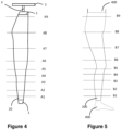
- the supporting element portions 4 to 12 have a plurality of circumferential length 48, 49, 50, 51, 52, 53, 54, 55, 56 at the different axial supporting element locations A1, A2, A3, A4, A5, A6, A7, A8, A9 as e.g. shown in figure 2 and figure 5 .
- circumferential length is meant the perimeter of the section of the supporting element portions 4 to 12 on a plane perpendicular to the axis C laying at the different axial supporting element locations A1 to A9.
- this perimeter is called "circumferential length".
- such a definition applies also to non-circumferential (e.g. elliptical) shapes.
- the supporting element portions 4-12 are thus arranged in series one with respect to the other along the central axis C. However, according to a preferred aspect, the supporting element portions 4-12 are separate one from another such that there is a distance D2 between two subsequent supporting element portions 4-12, measured along the axis C. In other words, the distance D2 forms a gap between two subsequent supporting element portions 4-12.
- Such a distance D2 is preferably between XX mm and YY mm.
- the supporting element portions 4-12 may be in one piece, or may be composed of a plurality of parts, joined one to the other. Preferred solutions provides for supporting element portions 4-12 made of two halves, i.e. two semi-portions 4a, 4b, 5a, 5b, etcetera, as e.g. shown in figure 1 and figure 3 .
- the supporting element 1 comprises at least a central rod 3, usually arranged at the central axis C of the supporting element 1.
- One or more mounting rods 14 usually branch from the central rod 3 (typically perpendicularly with respect to the central rod 3) and are connected to the supporting element portions 4-12.
- the supporting element portions are composed of a plurality of parts, there is usually a mounting rod 14 for each of these parts.
- each supporting element portion 4-12 is provided with two halves or semi-portions 4a, 4b, 5a, 5b.
- the supporting element 1 is thus preferably provided with two mounting rods 14 for each of its supporting element portions 4, 5, 6, 7, 8, 9, 10, 11, 12, i.e. one mounting rod 14 for each of the semi-portions 4a, 4b, 5a, 5b.
- the central rod 3 and the mounting rods 14 can be made of different materials in different embodiment, provided that enough stiffness is provided to the supporting element 1, e.g. they can be made of wood, plastic, metal, etc.
- the central rod 3 is usually mounted on a base support 2, usually in the shape of a plate, in order to avoid instability or potential tilting of the supporting element 1 when resting on a flat surface.
- At least part, preferably all of the supporting element portions 4-12 are multi-layer elements.
- the outer layer 60 (i.e. the one more distant from the central axis C and the one that in use is in contact with a garment), as better discussed below, is usually made of (or at least comprises) a heat conductive material, such as copper.
- the outer layer 60 may be made of a substantially two-dimensional element, partially folded in the shape of the relevant supporting element portion 4-12.
- the system 100 further comprises a plurality of heaters (41a, 41b), that are operable independently one from the other to independently heat each of the supporting mannequin portions 4, 5, 6, 7, 8, 9, 10, 11, 12.
- Preferred solutions provide for electrical heaters.
- these heaters comprise an electric source and a resistance, typically exploiting the Joule effect.
- the system 100 may be provided with an internal electric source (e.g. a battery) or, more frequently, be provided with a connection element 41a (e.g. a plug) configured to be connected to an external electric source.
- an internal electric source e.g. a battery
- a connection element 41a e.g. a plug
- the system 100 may also be provided with suitable electric means (e.g. AC-DC transformer, etc.) to adapt the electric power of the external source to the one needed by the resistance.
- suitable electric means e.g. AC-DC transformer, etc.
- the heaters (41a, 41b) usually comprise a heating element 41b, that is typically the resistive element of an electric heater, that is placed into contact with the outer layer 60 of the relevant supporting mannequin portion 4, 5, 6, 7, 8, 9, 10, 11, 12.
- the heating element 41b may be embodied differently in different embodiments.
- the heating element 41b may comprise one or more resistive electric cables, wound against the outer layer.
- the heating element 41b is shaped as a resistive plate, placed internally with respect to, and into contact with, the outer layer 60.
- the heating element 41b may be electrically insulated so that, when put into contact with the outer layer 60, e.g. a copper layer, the latter is heated without electric power being transmitted to the outer layer 60.
- the heating element 41b is preferably configured to avoid contact with the mounting rod 14.
- a heating element shaped as a resistive plate can be provided with one or more holes 410, through which the mounting rod 14 can pass, without touching the heating element 41b itself, in order to avoid direct heating on the mounting rod 14.
- the supporting mannequin portions 4, 5, 6, 7, 8, 9, 10, 11, 12 may also comprise insulation layers 42, comprising (or made of) a thermally insulating material, e.g. a ceramic material such as ceramic fibers, in order to allow heat to flow from the heating element towards the outer layer 60, but preventing (or at least limiting) flow of heat from the heating element 41b towards the central axis C of the supporting mannequin 1.
- a thermally insulating material e.g. a ceramic material such as ceramic fibers
- the supporting element 1 is preferably configured to avoid contact with the mounting rods 14.
- the insulation layers 42 may be provided with holes 410 through which the mounting rods 14 can pass.
- the mounting rods 14 are thus preferably connected to the outer layer 60 of the supporting element portions 4, 5, 6, 7, 8, 9, 10, 11, 12, while the heating element 41b is mounted onto the outer layer 60 (the insulating layer 42, if present, being mounted onto the heating element 41b and/or onto the outer layer 60).
- the system 100 further comprise sensors 13 configured to measure a compression at the different supporting mannequin portions 4, 5, 6, 7, 8, 9, 10, 11, 12 applied by the base garment 20 worn on the supporting mannequin 1.
- the sensors 13 are placed at the axial supporting mannequin location A1, A2, A3, A4, A5, A6, A7, A8, A9 themselves of the supporting mannequin 1.
- the sensors 13 are typically configured to measure a force, that can be converted into a compression via division of the force value by the area on which the sensed force is applied (e.g. the area of the outer surface of the relevant supporting mannequin portion, or half of the supporting mannequin portion, etc.). These kinds of sensors are known in the art.
- Preferred sensors 13 are load cells.
- the sensors 13 are coupled to the mounting rods 14, so that the sensors 13 can measure the force applied to the mounting rods 14. As discussed, this value can be converted into the compression exerted on the supporting mannequin portions at the different axial supporting mannequin locations A1, A2, A3, A4, A5, A6, A7, A8, A9.
- supporting mannequin portions 4, 5, 6, 7, 8, 9, 10, 11, 12 of preferred embodiments are provided with two semi-portions 4a, 4b, 5a, 5b each.
- Each semi-portion can be provided with a mounting rod 14 and thus, in turn, with a sensor 13.
- the two values read by the sensor can be treated (e.g. they can be averaged) to achieve a better precision.
- the system 100 further comprises a cooling system 101 configured to cool a garment worn on the supporting mannequin 1.
- the cooling system 101 may be arranged externally with respect to supporting mannequin, or at least part of the cooling system may be comprised in the supporting mannequin 1.
- An external cooling system 101 can e.g. be embodied as a plurality of gas blowers 102, configured to direct one or more flows of gas, preferably air, against the supporting mannequin 1 (and the garment possibly worn thereon).
- a cooling system 101 at least partially arranged within the supporting mannequin 1 may e.g. comprise a circuit for the circulation of a coolant 103 in the supporting mannequin 1.
- a further example of an internal cooling system may comprise Peltier devices.
- An external and (at least partially) internal cooling system may be alternative solutions for different embodiment, but they can also be combined in the same embodiment, e.g. gas blowers 102 and the circuit for a coolant 103 (and/or a peltier devices) may be used in the same embodiment.
- the system 100 usually comprise a control unit 104, e.g. a programmable logic control system (plc system) configured to control the operation of the supporting mannequin 1.
- the control unit is configured to control the heaters (41a, 41b) so that to independently heat the separate supporting mannequin portions 4, 5, 6, 7, 8, 9, 10, 11, 12.
- the control unit 104 can read the data sensed by the sensor 13.
- the control unit 104 may control the cooling system 101.
- a base garment 20 is treated onto the supporting mannequin 1.
- the base garment 20 comprises a fabric with uniform elastic properties in at least one direction, said base garment 20 comprising elastic fibers in elastic, i.e. stretch, yarns and has an elasticity of at least 15%, in at least one direction.
- the fabric is a woven fabric comprising elastomeric weft yarns.
- the fabric is more preferably a monolayer woven fabric.
- Elasticity can be measured with relevant ASTM standards, e.g. ASTM D3107 with respect to stretch, growth and recovery parameters. Standard parameters of the ASTM are used, e.g. 4.0 Ib and 30 minutes time for ASTM D3107.
- Elasticity i.e. stretch, of at least 15% is preferably at least in the weft direction.
- Preferred elastic fibers for the base garment 20 are known in the art and comprise elastomeric fibers and elastomeric yarns e.g. including elastane. Suitable elastic yarns are disclosed e.g. in application WO2012/062480 .
- the base garment 20 includes one or more substantially circumferential portions (e.g. legs for trousers, arms and/or body for shirts) that, when worn by a user 400, surrounds the user body and apply compressive forces to the body itself. Said compressive forces to the body provide a compression generated by elastomeric yarns provided in the weft direction.
- the method provides for providing the circumferential length (i.e. the perimeter) of the user profile 400, to which the garment treated with the method of the present invention is destined at selected locations of the user profile.
- mannequin 1 is reproducing a user body profile that includes a body portion from waist to legs to ankles, i.e. a typical body portion for trousers.
- a typical body portion for trousers i.e. a typical body portion for trousers.
- the circumferential length of a user profile 400 at the different axial size locations B1, B2, B3, B4, B5, B6, B7, B8, B9 may be acquired preferably through commercially available size charts.
- common reference table or charts can be used, in order to determine the circumferential length of a standard "S” user, of a standard “M” user, of a standard “L”, “XL”, “XXL”, etc. user.
- the axial size locations B1, B2, B3, B4, B5, B6, B7, B8, B9 and the axial supporting mannequin locations A1, A2, A3, A4, A5, A6, A7, A8, A9 are configured in order to match one with the other, i.e. the distance between the different axial size location is the same distance between the different axial supporting mannequin locations.
- the circumferential length of the final user profile 400 (being of a real user or a standard reference user) are determined.
- the desired fit for the garment on the user is determined. This is done via determining the desired compressions that the final compression garment 200 should apply onto the user at the different axial size locations B1, B2, B3, B4, B5, B6, B7, B8, B9, i.e. a value of compression for each of the axial size location of the user. This can be done via reference tables, or via the knowledge of the maker of the garment according to the requirements of the garment's final use; e.g. compression values required in a sport garment may be different from those in a pair of leggings, at the same axial locations.
- a base garment 20 as above discussed is thus produced.
- the base garment 20 has yet to be treated with the present method and thus, if worn on the final user, does not yet apply the desired compressions UC 1 , UC 2 , UC 3 ... UC N onto the final user.
- the same kind of base garment 20 can be produced for different kinds of final users.
- two identical base garment can be modified into two different final compression garments 200, each of them correctly fitting two differently sized users.
- a base garment 20 is worn onto the supporting mannequin, i.e. supporting mannequin, 1 to be treated.
- the base garment 20 and/or the supporting mannequin 1 are configured so that the base garment 20 applies a non null compression onto the mannequin 1 - i.e. at the axial locations the circumferential length of the base garment in a relaxed state is smaller than the circumferential length of supporting mannequin 1, so that it is stretched by the supporting mannequin when worn onto it.
- the actual compression AC 1 , AC 2 , AC 3 ... AC N exerted by the base garment onto the supporting mannequin at the axial supporting mannequin locations are determined.
- This determination can be indirect, e.g. by knowing the measures of the supporting mannequin 1, and the measures and elastic properties of the base garment 20.
- preferred solutions provide for sensors 13 applied onto the supporting mannequin to read the actual compressions AC 1 , AC 2 , AC 3 ... AC N exerted by the base garment 20 onto the supporting mannequin 1.
- target compressions TC 1 , TC 2 , TC 3 ... TC N are determined.
- the target compressions are the compressions that the base garment 20 should apply to the supporting mannequin 1 at the axial supporting mannequin location A1, A2, A3... AN so that, when worn by the user, the garment would apply the desired compressions UC 1 , UC 2 , UC 3 ... UC N .
- the supporting mannequin 1 is sized exactly as the final user.
- the target compressions TC 1 , TC 2 , TC 3 ... TC N coincide with the desired compression UC 1 , UC 2 , UC 3 ... UC N .
- the size of the supporting mannequin 1 is different from the size of the final user (i.e. the circumferential lengths of the supporting mannequin 1 at the axial supporting mannequin do not match the circumferential length of the user at the corresponding axial size locations).
- the target compression TC 1 , TC 2 , TC 3 ... TC N that the base garment should apply to the supporting mannequin 1 are different from the desired compressions UC 1 , UC 2 , UC 3 ... UC N .
- the difference between the target compressions and the desired compressions is thus a function of the differences between the circumferential lengths of the supporting mannequin 1 with respect to the circumferential lengths of the user.
- the target compressions TC 1 , TC 2 , TC 3 ... TC N can be evaluated as a function of the elastic properties of the base garment.
- a different, and simpler, approach to evaluate the value of the target compressions TC i at an axial supporting mannequin location Ai is to determine the target compression as a function of the ratio between the circumferential length of the supporting mannequin at the axial supporting mannequin location Ai and the user at the corresponding axial size location Bi.
- the supporting mannequin 1 is provided with a circumferential length CLS at each of the different axial supporting mannequin locations A1, A2, A3, ... AN and, accordingly, the final user body is characterized by a circumferential length CLU at each of the different axial size locations B1, B2, B3, ... B7.
- the ratio between the desired compressions UC i and the target compression TC i that should be exerted by the base garment on the supporting mannequin at the relevant axial supporting mannequin location Ai is substantially identical to the ratio between the circumferential length CLUi of the final user at the axial size location Bi and the circumferential length CLSi of the supporting mannequin at the relevant axial supporting mannequin location Ai.
- TCi is the target compression that the base garment should apply on the supporting mannequin at the i-th axial supporting mannequin location Ai, in order for the final compression garment to exert the desired compression UCi on the final user body at the corresponding axial size locations Bi.
- CLSi is the circumferential length of the supporting mannequin at axial supporting mannequin location Ai.
- UCi is the desired compression that the final compression garment should exert on the final user body at axial size location Bi.
- CLUi is the circumferential length of the final user body at axial size location Bi (in cm).
- the base garment is treated until the actual compressions AC 1 , AC 2 , AC 3 ... AC N become the target compressions.
- the supporting mannequin 1 (and thus the base garment20 worn on the supporting mannequin) is heated.
- each of the supporting mannequin portions is heated as a function of the difference between the actual compressions AC 1 , AC 2 , AC 3 ... AC N and the target compressions TC 1 , TC 2 , TC 3 ... TC N . Since this difference may be different at different axial supporting mannequin locations, different heat treatments can be applied at different axial supporting mannequin locations. Different heat treatments mean that the heat treatment can be applied for a different time and/or with a different temperature between different axial supporting mannequin locations A1, A2, A3, A4, A5, A6, A7, A8, A9.
- the base garment 20 is not heat treated at those axial supporting mannequin locations (i.e. the relevant supporting mannequin portions 4, 5, 6, 7, 8, 9, 10, 11, 12 are not heated).
- the temperature of the heat treatment is substantially the same, while only the time is changed between different axial supporting mannequin locations A1, A2, A3, A4, A5, A6, A7, A8, A9.
- the active heaters (41a, 41b) (usually the heating element 41b) reaches a temperature above 100°C, where with “active heaters” is meant the heaters (41a, 41b) actually heating the base garment 20, thus excluding the possibly non-operating ones - i.e. the ones coupled the axial supporting mannequin locations where the actual compression already matches the target compression.
- Applying heat to the base garment usually provides for a reduction of the value of the compression applied by the base garment 20 to the supporting mannequin 1.
- the target compression usually is lower than the actual compression (or at most equal to the actual compression when no heat treatment is needed).
- the base garment is dimensioned to initially apply a higher compression with respect to all of the possible final sizes of the possible user of the final compression garment 200, or to apply the desired compression to the smallest possible size of a user for the final compression garment 200.
- cooling of the base garment is operated, in order to fix the properties of the garment obtained with the heat treatment.
- the cooling system is configured to independently cool the garment at the different axial supporting mannequin locations.
- the properties of the base garment are known, it is possible to calculate the time needed for each heat treatment to transform the actual compression into the target compression.
- the heat treatments of the base garment at different axial size locations i.e. the heat treatment of the corresponding different mannequin portions
- the cooling is preferably "quick", so that the supporting mannequin is brought back to substantially room temperature in less than 30 seconds.
- a further aspect of the present invention relates to a method for modifying the elastic properties of a garment comprising the steps of a) producing a base garment 20 with a fabric comprising elastic fibres and having elasticity of at least 15% measured according to the ASTM D3107; b)The base garment 20 is worn on a supporting mannequin 1, having a plurality of supporting mannequin portions 4, 5, 6, 7, 8, 9, 10, 11, 12, the supporting mannequin 1 is provided with a plurality of heaters 41a, 41b operable independently one from the other to independently heat the supporting mannequin portions 4, 5, 6, 7, 8, 9, 10, 11, 12.
- the garment is therefore produced so that non null compressions are applied to said supporting mannequin 1 at the supporting mannequin portions 4, 5, 6, 7, 8, 9, 10, 11, 12 c) the heaters 41a, 41b heat the base garment 20 at said supporting mannequin portions 4, 5, 6, 7, 8, 9, 10, 11, 12, so that the non null compressions exerted by the base garment 20 are lowered d) the garment 20 is cooled.
- the active time of the different heaters 41a, 41b is different between different heaters 41a, 41b, to differently treat the garment at said supporting mannequin portions 4, 5, 6, 7, 8, 9, 10, 11, 12.
- the modified elastic properties of the final garment 200 can be detected by measuring at least one of stretch, growth and recovery parameters measured according to the ASTM D3107, of fabric samples taken at different locations of the garment.
- a further aspect of the present invention relates to a garment 200 as obtainable according to one or more of the above discussed aspects, wherein different axial size locations of the garment have different elastic properties, preferably at least one selected from stretch, growth recovery measured according to ASTM D3107 at least in the weft direction.
- the presence of different elastic properties of the fabric in the final garment 200 at different axial size locations is measurable by selecting a fabric sample 1 at one axial size location Bi of the heat-treated final garment 200, and a fabric sample 2 selected at another location Bj of the heat-treated final garment 200.
- Said axial size location Bi is different from said axial size location Bj.
- sample 1 and sample 2 have been heat treated at different temperatures and/or for different active times by the relevant heaters (41a, 41b) their elastic properties according to ASTM D3107 will be different.
- sample 1 and sample 2 are according to the ASTM D3107.
- sample 1 and sample 2 are centred on the corresponding axial size location Bi and Bj.
- the total area of each sample is divided by each corresponding axial size locations in two equal areas.
- sample 1 and sample 2 are measured according to ASTM D3107.
- At least one of the fabric's properties selected from stretch, growth and recovery measured according to ASTM D3107 is different between sample 1 and sample 2, preferably at least two or all the properties among stretch, growth and recovery measured according to ASTM D3107 are different between sample 1 and sample 2.
- the fabric of the garment has the same elastic properties in at least one direction, preferably at least in weft direction; in other words, stretch, growth and recovery measured according to ASTM D3107 are the same at all locations of the garment, i.e. a fabric sample 1 at one axial size location Bi of the base garment 20, and a fabric sample 2 selected at another, different, axial size location Bj of the base garment 20 have the same elastic properties measured according to ASTM D3107.
- Two identical base garment are differently treated on the same supporting mannequin in order to provide two final compression garments that fit in the same manner on two different kind of users.
- the first kind of user is smaller than the second kind user. For a user of the first kind, at the three axial size locations that correspond the axial supporting mannequin locations A1, A2, A3, the final compression garment 200 should exert the desired compressions UC 1 , UC 2 and UC 3 .
- a base garment 20 is prepared. When mounted onto the supporting mannequin, the base garment 20 exerts actual compressions AC 1 , AC 2 and AC 3 .
- the base garment 20 should be treated until it applies on the supporting mannequin the target compressions TC 1a , TC 2a and TC 3a . Then, since the actual compression AC 1 at the axial supporting mannequin location A1 is already equal to the target compression TC 1a , no heat treatment is applied to the base garment at the axial supporting mannequin location A1.
- Heating at the second axial supporting mannequin location A2 starts 15 seconds before the heating of the third axial supporting mannequin location A3.
- the whole base garment is cooled.
- a user of the first kind When worn by the a user of the first kind, such a user will feel the desired compressions UC 1 , UC 2 and UC 3 at his/her three axial size locations corresponding to the axial supporting mannequin locations A1, A2 and A3.
- the final compression garment 200 should exert the same desired compressions UC 1 , UC 2 and UC 3 as per the first kind of user.
- a base garment 20 is prepared. Since the base garment 20 for the second kind of user is identical to the base garment prepared for the first kind of user, when mounted onto the same supporting mannequin, the base garment 20 exerts the same actual compressions AC 1 , AC 2 and AC 3 .
- the base garment 20 should be treated until it applies on the supporting mannequin the target compressions TC 1b , TC 2b and TC 3b , that are lower than the target compression TC 1a , TC 2a and TC 3a for the first kind of user.
- Heating at the second axial supporting mannequin location A2 starts 25 seconds before the heating of the first axial supporting mannequin location A1 and 5 seconds before heating of the third axial supporting mannequin location A3.
- the whole base garment is cooled.
- such a user When worn by the second user, such a user will feel the desired compressions UC 1 , UC 2 and UC 3 at his/her three axial size locations corresponding to the axial supporting mannequin locations A1, A2 and A3, i.e. the same compression felt by a user of the first kind when wearing a final compression garment 200 destined to such a first user.
- two identical base garment 20 may be differently treated to provide two different final compression garment 200 having different fits for the same kind of users.
- the following further example shows an exemplary embodiment relating how to evaluate the target compressions TC 1 , TC 2 , TC 3 ... TC N as a function of the desired compressions UC 2 , UC 3 , ...,UC N , and of measures of the supporting mannequin and of the final user.
- the first column defines the different axial supporting mannequin locations A - A7.
- the circumferential length CLS1 - CLS7 of the supporting mannequin for each of the axial supporting mannequin locations A1 - A7 is shown.
- the desired compression UC 2 - UC 7 which is the compression that the final compression garment should exert on the final user body at the axial size location B1 - B7 is shown.
- the target compressions TC 1 - TC 7 to be applied on the supporting mannequin 1 in order to have the desired compressions UC 1 - UC 7 on the user are shown on the last column.
- the process of the invention changes the elastic properties of the fabric that has been treated; namely the stretch value of a treated fabric may be 38%, preferably 4% to 50%, preferably 10% to 50% less than the stretch value in the same non-treated fabric.
- the properties (measured according to ASTM D3107) of the fabric of a garment are different in different locations B1-B9 of the said garment where the heat treatment was carried out in a different manner, e.g. by heating for different times and/or at different temperatures.
- the difference in the value of stretch of a sample of fabric at e.g. location B1 will be different from (e.g. lower than) the stretch value of a sample of fabric at location B9.
- said difference expressed in percent of the ratio of the difference between greater (SB9) and smaller (SB1) value divided by the greater value, i.e. (SB9-SB1/SB9) *100 is in the range of 4 % to 50%, preferably 10% to 40%.
- a garment treated according to the process of the present invention there will be at least two portions of fabric at different locations having different properties that provide a ratio as above disclosed.
- two portions of fabric that have not been treated will have the same or substantially the same stretch values and the ratio will be 0% or an equivalent low value.
- the ratio of the stretch values (SX-SY/SX) *100 is in the range of 0% to 50%, depending on whether they were treated or not. In case the two samples were not treated (or were treated in identical manner) the said ratio (SX-SY/SX)*100 is 0% or about 0%. In case the two samples were treated for different times and/or at different temperatures so that sample X has greater stretch than sample Y, the ratio (SX-SY/SX)*100 is in the range of 4% to 50%, preferably 10% to 40%. In embodiments, all the couples of samples of a garment may give ratio values within the said range.
Abstract
Description
- The present invention relates to a method and a system for producing a compression garment and to the garments thus produced. In particular, the present invention relates to form-fitting stretchable compression garments and to methods for forming the same.
- In the textile industry it is standard practice to manufacture garments in several sizes in order to satisfy the needs of various wearers who wear different garments in their everyday activities and also in sport, fitness or training activities. Manufacturing of garments in several sizes is a costly activity.
- Wearers nowadays are more and more interested in form-fitting garments which can fit their body shape and provide a pleasant wearing feeling according to their needs and according to the activity they are performing.
- Today garments formed of stretchable fabrics have become very popular in the form-fitting garment industry. Stretchable garments typically comprise of elastomeric fibers that have a high elongation and an elastic behavior so that, after elongation, they return to substantially their initial dimensions. Additionally, compression sport garments are also of great interest because of their ability to help the wearer in practicing sport.
- As a result, a further problem with this type of garments is that the garments should always correctly fit to the body of the wearers. Usually, a garment that correctly fits to the body of a wearer provides a target (non-null) compression to the wearer body. In this regards, it may occur that a portion of the garment correctly fits to the wearer body (i.e. it applies a pre-defined target compression to the body), while a different portion of the same garment does not correctly fit to the wearer body, i.e. it applies a compression to the wearer body different from a pre-defined target compression, too little or too much compression, possibly no compression at all.
- It is thus an object of the present invention to solve the above mentioned problem.
- It is in particular an object of the present invention to provide a method for providing a compression garment in different sizes that is easier and more cost-effective than the prior art, and a relevant system for carrying out such a method.
- It is a further object of the present invention to provide a method, and a relevant system, for easily producing a compression garment that provides target compressions at different locations of the body of the final wearer.
- These and other problems are solved by the present invention according to one or more of the appended claims.
- In particular, it is an object of the present invention a method and a relevant system for producing a compression garment according to the independent claims, while preferred aspects are recited in the dependent claims. A garment as obtainable with the above discussed method is also an object of the invention.
- An aspect of the invention relates to method for producing a compression garment for a user from an elastic fabric, the method comprises the step of providing a base garment, fitting the garment on a supporting mannequin that has a plurality portions including a plurality of independent pressure sensors and of independent heating means to independently heat different portions of the garment, measuring the compression applied to the mannequin portions by the garment and heating selected portions of the mannequin to heat corresponding portions of the garment until the compression of the garment on the mannequin has reached a desired value.
- In particular, an aspect of the present invention relates to a method for producing a compression garment for a user, the garment having a plurality of circumferential lengths at different axial size locations to apply compression to corresponding locations of the user when the garment is worn, the method comprising the steps of: A. Providing a plurality of desired compressions to be applied by the garment on the user at said plurality of different axial size locations; B. Producing a base garment with a woven fabric comprising elastic fibers, and having elasticity, i.e. stretch of at least 15%; C. Wearing the base garment on a supporting element, the supporting element being provided with a plurality of heaters located at different axial locations of said supporting element and operable independently one from the other; D. Determining the actual compressions exerted by the base garment on the supporting element at different axial locations of said supporting element, corresponding to locations of the user; E. Determining target compressions to be exerted by the base garment on the supporting element at the different axial size locations of the garment so that the compression garment worn by the user exerts a desired compression at the different axial size locations; F. Operating the heaters of at least some of said axial locations of the supporting element to heat the base garment at said different axial size locations of the garment, so that the actual compressions exerted by the base garment are lowered to reach the target compressions; G. Cooling the base garment.
- In step B, the garment is produced so that, at step C, a non-null compression is applied by then garment to the supporting element at different axial locations in the step E.
- As discussed, in step B, the fabric of base garment has elasticity, i.e. a stretch, of at least 15%. The base garment is made of a woven fabric that when tested with ASTM D3107 (load of 3.0 Ib and testing time of 30 minutes), at least in one of weft or warp direction, has an elongation, or stretch, of at least 15%. Elasticity, i.e. stretchability, is preferably at least in the weft direction of the fabric in the garment, so as to provide the required compression on the user.
- The supporting element used to measure the compression and onto which the garment is fitted, is preferably in the form of a mannequin suitable for the type of compression garment, e.g. a pair of trousers, to be treated according to the invention process; the supporting element or mannequin is dimensioned and shaped according to a profile of a typical user/wearer. It is noted that the final compression garment can be produced according to pre-defined standard wearer size profile (as e.g. known from size charts, data banks, etc) or according to the measures of a modified profile of the user.
- Size charts for compression garments are part of the common general knowledge in the field and are commercially available e.g. from the firms Human Solutions and Alvanon. iSize is a portal and body dimensions data base developed by Human Solutions offering access to body dimensions and sizes tables for several Countries. Similarly, Avalon provides size tables, i.e. size charts, that identify the measures of the body of wearers for different sizes gender and countries. E.g. typically, a size chart would provide the measure of circumferential lengths measured at at least seven different axial locations along a leg of a wearer (i.e. the user).
- Typically, the mannequin acting as supporting element is made to reflect a profile of a user and is provided with a plurality of pressure (compression) sensors on a plurality of independent portions of the mannequin; this arrangement makes it possible to measure the compression forces at the selected axial locations. Advantageously the shape and dimensions, particularly the circumferential length, of said selected locations of the supporting mannequin are obtained from the above mentioned chart sizes.
- Thanks to the present invention, it is possible to manufacture base garments of the same size that can provide, after being treated with the above discussed method, many different final sizes and/or different fits (such as "skin fit", "slim fit", "carrot fit"); as a result, initial production of the garments is easier and cost effective, allowing in addition a high customizability of the final compression garment. Also, thanks to the present invention, it is possible to produce compression garments that provide a desired compression to areas of the wearer's body. This can be done for wearers having different body sizes, i.e. different user profiles, starting from base garments having the same dimensions and elastic (stretch) properties and making use of a same supporting element (supporting mannequin). In fact, thanks to the present invention, the elastic properties of the fabric of the base garment can be modified in order to have a compression garment that provides a desired compression profile (and wearing feeling) to the wearers.
- According to a possible aspect, the actual compressions exerted by the base garment on the supporting element, i.e. the mannequin, at different axial locations of the supporting element are measured via sensors of the supporting element.
- According to a possible aspect, the sensor measures the actual compression at least during the step of heating the base garment at the different axial supporting element locations. The actual compression exerted by the base garment decreases, under the action of the heating process, until it reaches the target compression. Typically, for a given axial location, the greater is the difference between the actual compression exerted by the base garment, as measured by the relevant sensor(s), and the target compression, the longer will be heating of the base garment.
- According to a possible aspect, the temperature of the heaters used to heat the base garment at the different axial supporting element locations may reach a temperature greater than 100°C, preferably in the range between 100°C and 130°C. This heating treatment results in the change of the properties of the elastic fibers in the yarns and thus in the change in the elastic properties of the base garment, providing a sort of heat setting to the fibers of the base garment.
- According to a possible aspect, the activation time of the different heaters is calculated as a function of the difference between the actual compression and target compressions measured at the relevant axial supporting element locations.
- According to a possible aspect, the operation of the heaters is started so that the heating treatment is ended substantially at the same time. Thanks to this, it is possible to start the cooling of the garment at the heated portions at different axial locations of the supporting element at the same time.
- According to a possible aspect, the cooling of the base garment is performed via at least one of: circulation of a coolant in the supporting element; blowing of a cooling gas, such as air, against the base garment; a Peltier device.
- According to a possible aspect, the cooling of the base garment provides a loss of temperature of the supporting element of at least 100°C degrees at the axial supporting element location. Preferably the above discussed loss of temperature occurs in less than 30 seconds.
- This quick cooling step allows to better fix the change in the properties (in particular elastic properties) of the garment, in order to correctly fit to the final wearer.
- According to a possible aspect, at least part of the cooling of the base garment is performed with the base garment still worn on the supporting element. Preferably the whole cooling step of the base garment is performed with the base garment still worn on the supporting element.
- Another aspect of the invention refers to a system to perform at least step C to G of the method for producing the compression garment. The system comprises a supporting element, generally in the form of a mannequin, provided with a plurality of separate portions at different axial locations of the supporting element. The separate portions of the mannequin are each provided with pressure sensors configured to detect the compression force generated by the garment onto the said portions. The said separate portions are also provided with a plurality of independently operable heaters configured to independently heat a garment worn on the supporting element at corresponding axial locations of the garment.
- In particular, the axial size locations of the garment and the axial supporting element/mannequin locations of the supporting element are configured in order to match one with the other, i.e. the distance between the different axial size locations in the garment is the same, or substantially the same, distance between the different axial locations supporting element.
- The system further comprises a cooling system configured to cool a garment worn on the supporting element and sensors configured to measure a compression at different supporting element portions applied by a base garment worn on the supporting element.
- The supporting mannequin is usually provided with a base support, typically comprising a plate, allowing resting of the supporting element on a flat surface.
- Preferred sensors are load cells configured to measure the compression exerted by the base garment on the supporting element at different axial locations, typically independently one from the other.
- More in general, during use, the separate portions of the supporting element are compressed by the garment so that such a compression can be measured by the sensors.
- Sensors, in particular load cells, can be mounted on a bearing rod or blade placed within the supporting element. A sensor rod can be placed between each of the supporting element portions and each of the sensors, allowing mounting of the portions themselves. The compression exerted on the portions by the base garment worn on the supporting mannequin acts also on the sensor rod so that it can be sensed by the sensor.
- Usually, considering the use condition, the bearing rod or blade is arranged substantially vertically, while the sensor rods are arranged substantially horizontally. Useful and preferred sensors are load cells; Force Sensitive Resistors (fsr) might also be used.
- According to a possible aspect, the system comprises a programmable logic control system (pic control system) configured to receive information from the pressure sensors and to activate the heating of the portions of the supporting element as a function of the data sensed by the sensor. In particular the PLC is programmed to possibly apply different heat treatments to different portions of the supporting element (and thus to the garment fitted onto the supporting element itself). A different heat treatment typically implies a different heating time.
- In a preferred embodiment there are provided by the software running in the PLC five different page on the PLC control system screen. Namely pages are provided for the step of calibrating load cells and for the step of correlating the load cells with compression testing devices provided with sensors so as to read numbers on screen as mmHg.
- In another page body measurements are entered and processed by an algorithm that creates target compression values according to existing values.
- A further step is visualized in a controlling page for the heating step, i.e. the "fixation" step; here it is calculated required amount of fixing-time for each part. As above mentioned, all the different axial locations of the garment might need to be fixed, i.e. heat treated, in different amounts according to the user profile.
- So for example while one part is heated for 660 seconds another part might start from 210 seconds. When the system is started initially only the portion to be heated for 660 seconds is activated and a count down starts till a time of 210 seconds from the end of the heating step is reached. At this point heating of the other part starts. In such a way, heating of all portions ends at the same time and the cooling step is started for all portions at the same time.
- A last page is created by testing each fabric several times, so as to create a chart for all the heatable portions of the mannequin that shows at each time how much the decrease of compression is obtained. That chart works synchronized with a controlling page while calculating necessary time of treatment.
- A further aspect of the invention relates to a garment as obtainable with the method according to one or more of the above discussed aspects.
- According to a more general aspect, the teaching of the present invention can be applied to modify the elastic properties of a garment. Exemplary parameters to estimate the modified elastic properties of a garment are stretch, growth and recovery parameters according to ASTM D3107.
- More in detail, an aspect of the present invention relates to a method for modifying the elastic properties of a garment comprising the steps of: a) Producing a base garment with a fabric comprising elastic fibers, and having elasticity of at least 15%; b) Wearing said base garment on a supporting element, the supporting element having a plurality of axial supporting element portions , the supporting element being provided with a plurality of heaters operable independently one from the other to independently heat the supporting element portions, wherein the garment is produced so that, non null compressions are applied to said supporting element (1) at the supporting element portions; c) Operating the heaters to heat the base garment at said supporting element portions, so that the non null compressions exerted by the base garment are lowered; d) Cooling the base garment.
- As per above, sensors of the supporting element can measure said non-null compressions.
- In addition to that, it is possible that the active time of the different heaters is different between different heaters, to differently treat the garment at different axial supporting element locations.
- A further aspect of the invention relates to a garment as obtainable according to one or more of the above discussed aspects, wherein different axial size location of the garment has different elastic properties, preferably at least one selected from stretch, growth, recovery measured according to ASTM D3107 at least in the weft direction.
- Further aspects and advantages in accordance with the present disclosure will be discussed more in detail with reference to the enclosed drawings, given by way of non-limiting example, wherein:
-
Fig. 1 shows a perspective view of a supporting element of a system according to a possible embodiment of the present invention; -
Fig. 2 shows a lateral view of the supporting element offigure 1 ; -
Fig. 3 shows a schematic section view of two supporting element portions of the supporting element offigure 1 ; -
Fig. 4 shows an upside down lateral view the supporting element offigure 1 and
a base garment worn on the supporting element according to a possible embodiment of the present invention. -
Fig. 5 shows a compression garment worn on a user body according to a possible embodiment of the present invention. - The
system 100 comprises a supportingelement 1 comprising a plurality of supportingelement portions element 1 are configured in order to match one with the other, i.e. the distance between the different axial size location is the same distance between the different axial supporting element locations. - In the embodiment shown in the figures, there are nine axial supporting element locations A1 - A9, and nine supporting element portions 4 - 12. However, the number of supporting element portions and locations may be different in different embodiments. The following description applies to all of these embodiments, independently from the number of portions and locations.
- The different axial supporting element location A1-A9 are defined as location along the central axis C of the supporting element, i.e. the supporting mannequin, 1, where the central axis C is the axis of the main dimension of extension D1 (i.e. the greater one) of the supporting
mannequin 1. - Preferably, the different axial supporting element locations A1-A9 are positioned at the midpoint of a height H1 of each supporting
element portions upper end 58 of a supporting element portion 4-12 and thelower end 46 of the same supporting element portion 4-12 as e.g. shown infigure 3 , wherein "upper" and "lower" refers to the condition of the supporting element during use. - The supporting element portions 4-12 may have different shapes in different embodiment; in preferred solutions, however, the supporting mannequin portions 4-12 have a substantially circumferential cross section, on a plane perpendicular to the central axis C that may reflect at least in part the corresponding section of a user profile, as visible in
figures 1 and2 . The perimeter of such a circumference may be constant along the axis C (i.e. the supportingelement portions - In general, the supporting
element portions 4 to 12 have a plurality ofcircumferential length figure 2 andfigure 5 . With circumferential length is meant the perimeter of the section of the supportingelement portions 4 to 12 on a plane perpendicular to the axis C laying at the different axial supporting element locations A1 to A9. For easiness, due to the supporting element having preferably a circumferential section, this perimeter is called "circumferential length". In any case, such a definition applies also to non-circumferential (e.g. elliptical) shapes. - The supporting element portions 4-12 are thus arranged in series one with respect to the other along the central axis C. However, according to a preferred aspect, the supporting element portions 4-12 are separate one from another such that there is a distance D2 between two subsequent supporting element portions 4-12, measured along the axis C. In other words, the distance D2 forms a gap between two subsequent supporting element portions 4-12.
- As a result, considering the use condition of the supporting
element 1, there is a distance D2 between the lower-end 46 of a supporting element portion 4-12 and the upper-end 59 of the subsequently below supporting element portion 4-12 as e.g. shown schematically infigure 3 . Such a distance D2 is preferably between XX mm and YY mm. - The supporting element portions 4-12 may be in one piece, or may be composed of a plurality of parts, joined one to the other. Preferred solutions provides for supporting element portions 4-12 made of two halves, i.e. two
semi-portions figure 1 andfigure 3 . - Preferably, the supporting
element 1 comprises at least acentral rod 3, usually arranged at the central axis C of the supportingelement 1. One or moremounting rods 14 usually branch from the central rod 3 (typically perpendicularly with respect to the central rod 3) and are connected to the supporting element portions 4-12. In particular, there is usually at least one mountingrod 14 for each of the supporting element portions 4-12. If the supporting element portions are composed of a plurality of parts, there is usually a mountingrod 14 for each of these parts. - As an example, in preferred embodiments, as the one shown in the figures, each supporting element portion 4-12 is provided with two halves or semi-portions 4a, 4b, 5a, 5b. In these embodiments, the supporting
element 1 is thus preferably provided with two mountingrods 14 for each of its supportingelement portions rod 14 for each of the semi-portions 4a, 4b, 5a, 5b. - The
central rod 3 and the mountingrods 14 can be made of different materials in different embodiment, provided that enough stiffness is provided to the supportingelement 1, e.g. they can be made of wood, plastic, metal, etc. - The
central rod 3 is usually mounted on abase support 2, usually in the shape of a plate, in order to avoid instability or potential tilting of the supportingelement 1 when resting on a flat surface. - At least part, preferably all of the supporting element portions 4-12 are multi-layer elements.
- The outer layer 60 (i.e. the one more distant from the central axis C and the one that in use is in contact with a garment), as better discussed below, is usually made of (or at least comprises) a heat conductive material, such as copper. The
outer layer 60 may be made of a substantially two-dimensional element, partially folded in the shape of the relevant supporting element portion 4-12. - The
system 100 further comprises a plurality of heaters (41a, 41b), that are operable independently one from the other to independently heat each of the supportingmannequin portions - Preferred solutions provide for electrical heaters. Usually, these heaters (41a, 41b) comprise an electric source and a resistance, typically exploiting the Joule effect. The
system 100 may be provided with an internal electric source (e.g. a battery) or, more frequently, be provided with aconnection element 41a (e.g. a plug) configured to be connected to an external electric source. - The
system 100 may also be provided with suitable electric means (e.g. AC-DC transformer, etc.) to adapt the electric power of the external source to the one needed by the resistance. - The heaters (41a, 41b) usually comprise a
heating element 41b, that is typically the resistive element of an electric heater, that is placed into contact with theouter layer 60 of the relevant supportingmannequin portion heating element 41b may be embodied differently in different embodiments. As an example, theheating element 41b may comprise one or more resistive electric cables, wound against the outer layer. - In preferred embodiments, like the one shown in
figure 3 , theheating element 41b is shaped as a resistive plate, placed internally with respect to, and into contact with, theouter layer 60. Theheating element 41b may be electrically insulated so that, when put into contact with theouter layer 60, e.g. a copper layer, the latter is heated without electric power being transmitted to theouter layer 60. - The
heating element 41b is preferably configured to avoid contact with the mountingrod 14. As an example, a heating element shaped as a resistive plate can be provided with one ormore holes 410, through which the mountingrod 14 can pass, without touching theheating element 41b itself, in order to avoid direct heating on the mountingrod 14. - The supporting
mannequin portions outer layer 60, but preventing (or at least limiting) flow of heat from theheating element 41b towards the central axis C of the supportingmannequin 1. As per theheating element 41b, the supportingelement 1 is preferably configured to avoid contact with the mountingrods 14. As an example, the insulation layers 42 may be provided withholes 410 through which the mountingrods 14 can pass. - As a result, the mounting
rods 14 are thus preferably connected to theouter layer 60 of the supportingelement portions heating element 41b is mounted onto the outer layer 60 (the insulatinglayer 42, if present, being mounted onto theheating element 41b and/or onto the outer layer 60). - The
system 100 further comprisesensors 13 configured to measure a
compression at the different supportingmannequin portions base garment 20 worn on the supportingmannequin 1. Preferably, thesensors 13 are placed at the axial supporting mannequin location A1, A2, A3, A4, A5, A6, A7, A8, A9 themselves of the supportingmannequin 1. Thesensors 13 are typically configured to measure a force, that can be converted into a compression via division of the force value by the area on which the sensed force is applied (e.g. the area of the outer surface of the relevant supporting mannequin portion, or half of the supporting mannequin portion, etc.). These kinds of sensors are known in the art.Preferred sensors 13 are load cells. - Preferably, the
sensors 13 are coupled to the mountingrods 14, so that thesensors 13 can measure the force applied to the mountingrods 14. As discussed, this value can be converted into the compression exerted on the supporting mannequin portions at the different axial supporting mannequin locations A1, A2, A3, A4, A5, A6, A7, A8, A9. - As mentioned, supporting
mannequin portions semi-portions rod 14 and thus, in turn, with asensor 13. As a result, there can be two sensors at each axial supporting mannequin location A1-A9. The two values read by the sensor can be treated (e.g. they can be averaged) to achieve a better precision. - The
system 100 further comprises acooling system 101 configured to cool a garment worn on the supportingmannequin 1. Thecooling system 101 may be arranged externally with respect to supporting mannequin, or at least part of the cooling system may be comprised in the supportingmannequin 1. Anexternal cooling system 101 can e.g. be embodied as a plurality ofgas blowers 102, configured to direct one or more flows of gas, preferably air, against the supporting mannequin 1 (and the garment possibly worn thereon). Acooling system 101 at least partially arranged within the supportingmannequin 1 may e.g. comprise a circuit for the circulation of acoolant 103 in the supportingmannequin 1. A further example of an internal cooling system may comprise Peltier devices. - An external and (at least partially) internal cooling system may be alternative solutions for different embodiment, but they can also be combined in the same embodiment,
e.g. gas blowers 102 and the circuit for a coolant 103 (and/or a peltier devices) may be used in the same embodiment. - The above discussed examples (i.e. circulation of a coolant in the supporting mannequin, blowing of a gas, preferably air, against the base garment and use of peltier devices) are the preferred solutions for the
cooling system 101. - Other cooling system may as well be used, provided that they are capable of providing an effective cooling of the garment worn on the supporting
mannequin 1. In particular, as better discussed below, a quick cooling is preferred for the method of the present invention. - The
system 100 usually comprise acontrol unit 104, e.g. a programmable logic control system (plc system) configured to control the operation of the supportingmannequin 1. Usually, the control unit is configured to control the heaters (41a, 41b) so that to independently heat the separate supportingmannequin portions control unit 104 can read the data sensed by thesensor 13. Thecontrol unit 104 may control thecooling system 101. - As better discussed below, according to the method invention, a
base garment 20 is treated onto the supportingmannequin 1. Thebase garment 20 comprises a fabric with uniform elastic properties in at least one direction, saidbase garment 20 comprising elastic fibers in elastic, i.e. stretch, yarns and has an elasticity of at least 15%, in at least one direction.The fabric is a woven fabric comprising elastomeric weft yarns. The fabric is more preferably a monolayer woven fabric. Elasticity can be measured with relevant ASTM standards, e.g. ASTM D3107 with respect to stretch, growth and recovery parameters. Standard parameters of the ASTM are used, e.g. 4.0 Ib and 30 minutes time for ASTM D3107. - Elasticity, i.e. stretch, of at least 15% is preferably at least in the weft direction. Preferred elastic fibers for the
base garment 20 are known in the art and comprise elastomeric fibers and elastomeric yarns e.g. including elastane. Suitable elastic yarns are disclosed e.g. in applicationWO2012/062480 . - The
base garment 20 includes one or more substantially circumferential portions (e.g. legs for trousers, arms and/or body for shirts) that, when worn by auser 400, surrounds the user body and apply compressive forces to the body itself. Said compressive forces to the body provide a compression generated by elastomeric yarns provided in the weft direction.In particular, as better discussed below, the method provides for providing the circumferential length (i.e. the perimeter) of theuser profile 400, to which the garment treated with the method of the present invention is destined at selected locations of the user profile. - In fact, as above discussed,
mannequin 1 is reproducing a user body profile that includes a body portion from waist to legs to ankles, i.e. a typical body portion for trousers. Considering an axis of these portions, extending along the main (greater) dimension of the portions (e.g. the axis of a leg of a user), it is possible to know the perimeter of these portions at different axial size locations B1, B2, B3, B4, B5, B6, B7, B8, B9 located along the axis of the portions of the user body as e.g. shown infigure 5 . The circumferential length of auser profile 400 at the different axial size locations B1, B2, B3, B4, B5, B6, B7, B8, B9 may be acquired preferably through commercially available size charts. In this case, common reference table or charts can be used, in order to determine the circumferential length of a standard "S" user, of a standard "M" user, of a standard "L", "XL", "XXL", etc. user. - In particular, the axial size locations B1, B2, B3, B4, B5, B6, B7, B8, B9 and the axial supporting mannequin locations A1, A2, A3, A4, A5, A6, A7, A8, A9 are configured in order to match one with the other, i.e. the distance between the different axial size location is the same distance between the different axial supporting mannequin locations.
- As a result, in order to carry out the present method, the circumferential length of the final user profile 400 (being of a real user or a standard reference user) are determined.
- Subsequently, the desired fit for the garment on the user is determined. This is done via determining the desired compressions that the
final compression garment 200 should apply onto the user at the different axial size locations B1, B2, B3, B4, B5, B6, B7, B8, B9, i.e. a value of compression for each of the axial size location of the user. This can be done via reference tables, or via the knowledge of the maker of the garment according to the requirements of the garment's final use; e.g. compression values required in a sport garment may be different from those in a pair of leggings, at the same axial locations. - In other words, given N axial size locations B1, B2, B3 ... BN on the
user profile 400, the values of N desired compression UC1, UC2, UC3 ... UCN that thefinal compression garment 200 should apply to the final user are determined. - A
base garment 20 as above discussed is thus produced. Thebase garment 20 has yet to be treated with the present method and thus, if worn on the final user, does not yet apply the desired compressions UC1, UC2, UC3 ... UCN onto the final user. Also, according to an advantageous aspect of the invention, the same kind ofbase garment 20 can be produced for different kinds of final users. By differently treating these base garments with the present method, two identical base garment can be modified into two differentfinal compression garments 200, each of them correctly fitting two differently sized users. - In general, a
base garment 20 is worn onto the supporting mannequin, i.e. supporting mannequin, 1 to be treated. Thebase garment 20 and/or the supportingmannequin 1 are configured so that thebase garment 20 applies a non null compression onto the mannequin 1 - i.e. at the axial locations the circumferential length of the base garment in a relaxed state is smaller than the circumferential length of supportingmannequin 1, so that it is stretched by the supporting mannequin when worn onto it. - Subsequently, the actual compression AC1, AC2, AC3 ... ACN exerted by the base garment onto the supporting mannequin at the axial supporting mannequin locations (that, as discussed, match the axial size locations) are determined. This determination can be indirect, e.g. by knowing the measures of the supporting
mannequin 1, and the measures and elastic properties of thebase garment 20. However, preferred solutions provide forsensors 13 applied onto the supporting mannequin to read the actual compressions AC1, AC2, AC3 ... ACN exerted by thebase garment 20 onto the supportingmannequin 1. - Subsequently, target compressions TC1, TC2, TC3 ... TCN are determined. The target compressions are the compressions that the
base garment 20 should apply to the supportingmannequin 1 at the axial supporting mannequin location A1, A2, A3... AN so that, when worn by the user, the garment would apply the desired compressions UC1, UC2, UC3 ... UCN. - In a possible condition, the supporting
mannequin 1 is sized exactly as the final user. In this case, the target compressions TC1, TC2, TC3 ... TCN coincide with the desired compression UC1, UC2, UC3 ... UCN. - Generally, the size of the supporting
mannequin 1 is different from the size of the final user (i.e. the circumferential lengths of the supportingmannequin 1 at the axial supporting mannequin do not match the circumferential length of the user at the corresponding axial size locations). - In this case, the target compression TC1, TC2, TC3 ... TCN that the base garment should apply to the supporting
mannequin 1 are different from the desired compressions UC1, UC2, UC3 ... UCN. The difference between the target compressions and the desired compressions is thus a function of the differences between the circumferential lengths of the supportingmannequin 1 with respect to the circumferential lengths of the user. - According to one aspect, the target compressions TC1, TC2, TC3 ... TCN can be evaluated as a function of the elastic properties of the base garment.
- A different, and simpler, approach to evaluate the value of the target compressions TCi at an axial supporting mannequin location Ai, is to determine the target compression as a function of the ratio between the circumferential length of the supporting mannequin at the axial supporting mannequin location Ai and the user at the corresponding axial size location Bi.
- In more detail, the supporting
mannequin 1 is provided with a circumferential length CLS at each of the different axial supporting mannequin locations A1, A2, A3, ... AN and, accordingly, the final user body is characterized by a circumferential length CLU at each of the different axial size locations B1, B2, B3, ... B7. - Given the desired compressions UCi at an axial size locations Bi, the ratio between the desired compressions UCi and the target compression TCi that should be exerted by the base garment on the supporting mannequin at the relevant axial supporting mannequin location Ai is substantially identical to the ratio between the circumferential length CLUi of the final user at the axial size location Bi and the circumferential length CLSi of the supporting mannequin at the relevant axial supporting mannequin location Ai. As a result, the target compression at an axial supporting mannequin location Ai can be evaluated according to formula TCi = UCi * CLSi / CLUi.
- As evident from the above discussion, in the above formula, the symbols are as follows.
- TCi is the target compression that the base garment should apply on the supporting mannequin at the i-th axial supporting mannequin location Ai, in order for the final compression garment to exert the desired compression UCi on the final user body at the corresponding axial size locations Bi.
- CLSi is the circumferential length of the supporting mannequin at axial supporting mannequin location Ai.
- UCi is the desired compression that the final compression garment should exert on the final user body at axial size location Bi.
- CLUi is the circumferential length of the final user body at axial size location Bi (in cm).
- Once the target compressions TC1, TC2, TC3 ... TCN are determined, the base garment is treated until the actual compressions AC1, AC2, AC3 ... ACN become the target compressions.
- In particular, the supporting mannequin 1 (and thus the base garment20 worn on the supporting mannequin) is heated. In more detail, each of the supporting mannequin portions is heated as a function of the difference between the actual compressions AC1, AC2, AC3 ... ACN and the target compressions TC1, TC2, TC3 ... TCN. Since this difference may be different at different axial supporting mannequin locations, different heat treatments can be applied at different axial supporting mannequin locations. Different heat treatments mean that the heat treatment can be applied for a different time and/or with a different temperature between different axial supporting mannequin locations A1, A2, A3, A4, A5, A6, A7, A8, A9.
- It is also possible that at some axial supporting mannequin locations, the actual compression is already equal to the target compression. In that case, the
base garment 20 is not heat treated at those axial supporting mannequin locations (i.e. the relevant supportingmannequin portions - Preferably, where the heat treatment is applied, the temperature of the heat treatment is substantially the same, while only the time is changed between different axial supporting mannequin locations A1, A2, A3, A4, A5, A6, A7, A8, A9. In particular, the active heaters (41a, 41b) (usually the
heating element 41b) reaches a temperature above 100°C, where with "active heaters" is meant the heaters (41a, 41b) actually heating thebase garment 20, thus excluding the possibly non-operating ones - i.e. the ones coupled the axial supporting mannequin locations where the actual compression already matches the target compression. - Applying heat to the base garment usually provides for a reduction of the value of the compression applied by the
base garment 20 to the supportingmannequin 1. The longer the treatment and/or the higher the temperature, the higher will be the lowering of the compression applied by thebase garment 20. As a result, the target compression usually is lower than the actual compression (or at most equal to the actual compression when no heat treatment is needed). In view of that, it is preferred that the base garment is dimensioned to initially apply a higher compression with respect to all of the possible final sizes of the possible user of thefinal compression garment 200, or to apply the desired compression to the smallest possible size of a user for thefinal compression garment 200. - Subsequently, cooling of the base garment is operated, in order to fix the properties of the garment obtained with the heat treatment. As with the heating, the cooling system is configured to independently cool the garment at the different axial supporting mannequin locations.
- However, this may be a difficult operation to achieve. In addition to that, it is possible to cool a portion of the base garment that was not heat treated (as the actual compression already matched the target compression) without particular side effects. As a result, it is preferable that cooling is applied to the whole base garment, at the same time.
- Since the properties of the base garment are known, it is possible to calculate the time needed for each heat treatment to transform the actual compression into the target compression. As a result, the heat treatments of the base garment at different axial size locations (i.e. the heat treatment of the corresponding different mannequin portions) can be started at different times, so that all the heat treatments are ended substantially at the same time, thus allowing cooling of the whole base garment.
- As above discussed, the cooling is preferably "quick", so that the supporting mannequin is brought back to substantially room temperature in less than 30 seconds.
- A further aspect of the present invention relates to a method for modifying the elastic properties of a garment comprising the steps of a) producing a
base garment 20 with a fabric comprising elastic fibres and having elasticity of at least 15% measured according to the ASTM D3107; b)Thebase garment 20 is worn on a supportingmannequin 1, having a plurality of supportingmannequin portions mannequin 1 is provided with a plurality ofheaters mannequin portions mannequin 1 at the supportingmannequin portions heaters base garment 20 at said supportingmannequin portions base garment 20 are lowered d) thegarment 20 is cooled. - According to a possible aspect, the active time of the
different heaters different heaters mannequin portions - The modified elastic properties of the
final garment 200 can be detected by measuring at least one of stretch, growth and recovery parameters measured according to the ASTM D3107, of fabric samples taken at different locations of the garment. - A further aspect of the present invention relates to a
garment 200 as obtainable according to one or more of the above discussed aspects, wherein different axial size locations of the garment have different elastic properties, preferably at least one selected from stretch, growth recovery measured according to ASTM D3107 at least in the weft direction. - The presence of different elastic properties of the fabric in the
final garment 200 at different axial size locations, i.e. at different axial locations in the garment, is measurable by selecting afabric sample 1 at one axial size location Bi of the heat-treatedfinal garment 200, and afabric sample 2 selected at another location Bj of the heat-treatedfinal garment 200. Said axial size location Bi is different from said axial size location Bj. - If
sample 1 andsample 2 have been heat treated at different temperatures and/or for different active times by the relevant heaters (41a, 41b) their elastic properties according to ASTM D3107 will be different. - Dimensions of
sample 1 andsample 2 are according to the ASTM D3107. Preferablysample 1 andsample 2 are centred on the corresponding axial size location Bi and Bj. In other words, the total area of each sample is divided by each corresponding axial size locations in two equal areas. - The different elastic properties of
sample 1 andsample 2 are measured according to ASTM D3107. - At least one of the fabric's properties selected from stretch, growth and recovery measured according to ASTM D3107 is different between
sample 1 andsample 2, preferably at least two or all the properties among stretch, growth and recovery measured according to ASTM D3107 are different betweensample 1 andsample 2. - In the
untreated base garment 20, as the fabric is structurally and chemically identical in all its parts, the fabric of the garment has the same elastic properties in at least one direction, preferably at least in weft direction; in other words, stretch, growth and recovery measured according to ASTM D3107 are the same at all locations of the garment, i.e. afabric sample 1 at one axial size location Bi of thebase garment 20, and afabric sample 2 selected at another, different, axial size location Bj of thebase garment 20 have the same elastic properties measured according to ASTM D3107. - Some exemplary embodiments are discussed here below.
- Two identical base garment are differently treated on the same supporting mannequin in order to provide two final compression garments that fit in the same manner on two different kind of users.
- The exemplary data discussed in the first example is as follows.
Table 1. axial size location B1 B2 B3 actual compression AC1 AC2 AC3 desired compression UC1 UC2 UC3 target compression 1st user TC1a = AC1 TC2a= 0.7∗AC2 TC3a = 0.8∗AC3 heat time 1st user 0s 35s 20s target compression 2nd user TC1b =0.9 ∗AC1 TC2b = 0.6∗AC2 TC3b = 0.6∗AC3 heat time 2nd user 15s 40s 35s
For a user of the first kind, at the three axial size locations that correspond the axial supporting mannequin locations A1, A2, A3, thefinal compression garment 200 should exert the desired compressions UC1, UC2 and UC3. - A
base garment 20 is prepared. When mounted onto the supporting mannequin, thebase garment 20 exerts actual compressions AC1, AC2 and AC3. - In order for the
final compression garment 200 to exert the desired compressions UC1, UC2 and UC3, it is determined that thebase garment 20 should be treated until it applies on the supporting mannequin the target compressions TC1a, TC2a and TC3a. Then, since the actual compression AC1 at the axial supporting mannequin location A1 is already equal to the target compression TC1a, no heat treatment is applied to the base garment at the axial supporting mannequin location A1. In order to lower the other two actual compressions AC1 and AC2 until they reach the relevant target compressions TC1a and TC2a, it is determined that a heating of 35 seconds is needed at the second axial supporting mannequin location A2, and a heating of 20s is needed at the third axial supporting mannequin location A3. - Heating at the second axial supporting mannequin location A2 starts 15 seconds before the heating of the third axial supporting mannequin location A3.
- At the end of the heating process, the whole base garment is cooled. When worn by the a user of the first kind, such a user will feel the desired compressions UC1, UC2 and UC3 at his/her three axial size locations corresponding to the axial supporting mannequin locations A1, A2 and A3.
- For a user of the second kind, at the three axial size locations that correspond the axial supporting mannequin locations A1, A2, A3, the
final compression garment 200 should exert the same desired compressions UC1, UC2 and UC3 as per the first kind of user. - A
base garment 20 is prepared. Since thebase garment 20 for the second kind of user is identical to the base garment prepared for the first kind of user, when mounted onto the same supporting mannequin, thebase garment 20 exerts the same actual compressions AC1, AC2 and AC3. - However, since the second user is bigger than the first user, in order for the
final compression garment 200 to exert the desired compressions UC1, UC2 and UC3, it is determined that thebase garment 20 should be treated until it applies on the supporting mannequin the target compressions TC1b, TC2b and TC3b, that are lower than the target compression TC1a, TC2a and TC3a for the first kind of user. - In order to lower the actual compressions AC1, AC2 and AC3 until they reach the relevant target compressions TC1b, TC2b and TC2c, it is determined that a heating of 10, 40 and 35 seconds are needed respectively at the three axial supporting mannequin locations A1, A2 and A3.
- Heating at the second axial supporting mannequin location A2 starts 25 seconds before the heating of the first axial supporting mannequin location A1 and 5 seconds before heating of the third axial supporting mannequin location A3.
- At the end of the heating process, the whole base garment is cooled. When worn by the second user, such a user will feel the desired compressions UC1, UC2 and UC3 at his/her three axial size locations corresponding to the axial supporting mannequin locations A1, A2 and A3, i.e. the same compression felt by a user of the first kind when wearing a
final compression garment 200 destined to such a first user. - Similarly, two
identical base garment 20 may be differently treated to provide two differentfinal compression garment 200 having different fits for the same kind of users. - The following further example shows an exemplary embodiment relating how to evaluate the target compressions TC1, TC2, TC3 ... TCN as a function of the desired compressions UC2, UC3, ...,UCN, and of measures of the supporting mannequin and of the final user.
- In particular, in the following example, seven different axial supporting mannequin location A1 - A7 and thus seven different corresponding axial size location (locations of the garment) B1 - B7 are considered.
The first column defines the different axial supporting mannequin locations A - A7. In the second column, the circumferential length CLS1 - CLS7 of the supporting mannequin for each of the axial supporting mannequin locations A1 - A7 is shown. In the third column, the desired compression UC2 - UC7, which is the compression that the final compression garment should exert on the final user body at the axial size location B1 - B7 is shown. - The target compressions TC1 - TC7 to be applied on the supporting
mannequin 1 in order to have the desired compressions UC1 - UC7 on the user are shown on the last column. In particular, as per the simplified approach previously discussed, the values of the target compressions are evaluated according to the formula TCi = UCi * CLSi / CLUi.
As an example, considering axial supporting mannequin location A1, the above formula equals to: TC1 = UC1 * CLS1 / CLU1 = 15 mmHg * 28.2 cm / 23 cm = 18.4 mmHg. - The above formula is applied to all of the axial supporting mannequin locations A1 - A7, to obtain the following data:
Table 2 Axial supporting mannequin location Circumferential length (CLS-i) - Supporting mannequin (cm) Circumferential length (CLU-i) - User (cm) Desired compression - User (UC-i) (mmHg) Target compression - Supporting mannequin (TC-i) (mmHg) A1 (ankle) 28,2 23 15 18,4 A2 32,8 29 12,8 14,5 A3 (calf) 37,5 36 9,8 10,2 A4 41 35 9 10,5 A5 44 40 8,3 9,1 A6 51 50 7,5 7,7 A7 (tight) 56,5 58 6 5,8 - As above mentioned, the process of the invention changes the elastic properties of the fabric that has been treated; namely the stretch value of a treated fabric may be 38%, preferably 4% to 50%, preferably 10% to 50% less than the stretch value in the same non-treated fabric.
- As discussed, after the process of the invention is carried out on a garment, the properties (measured according to ASTM D3107) of the fabric of a garment are different in different locations B1-B9 of the said garment where the heat treatment was carried out in a different manner, e.g. by heating for different times and/or at different temperatures. As an example the difference in the value of stretch of a sample of fabric at e.g. location B1 will be different from (e.g. lower than) the stretch value of a sample of fabric at location B9. In embodiments, said difference expressed in percent of the ratio of the difference between greater (SB9) and smaller (SB1) value divided by the greater value, i.e. (SB9-SB1/SB9) *100, is in the range of 4 % to 50%, preferably 10% to 40%.
- More generally, in a garment treated according to the process of the present invention, there will be at least two portions of fabric at different locations having different properties that provide a ratio as above disclosed. In the same garment two portions of fabric that have not been treated will have the same or substantially the same stretch values and the ratio will be 0% or an equivalent low value.
- As an example for two samples taken from two parts X and Y of the garment, e.g. a pair of pants, the ratio of the stretch values (SX-SY/SX) *100 is in the range of 0% to 50%, depending on whether they were treated or not. In case the two samples were not treated (or were treated in identical manner) the said ratio (SX-SY/SX)*100 is 0% or about 0%. In case the two samples were treated for different times and/or at different temperatures so that sample X has greater stretch than sample Y, the ratio (SX-SY/SX)*100 is in the range of 4% to 50%, preferably 10% to 40%. In embodiments, all the couples of samples of a garment may give ratio values within the said range.
Claims (16)
- A method for producing a compression garment (200) for a user, the garment having a plurality of size circumferential lengths at different axial size locations (B1, B2, B3, B4, B5, B6, B7, B8, B9) to apply compression to corresponding locations of the user when said garment is worn, the method comprising the steps of:A. Providing a plurality of desired compressions to be applied by the compression garment (200) on the user (400) at said plurality of different axial size locations (B1-B9);B. Producing a base garment (20) with a woven fabric comprising elastic fibers, said fabric having a stretch of at least 15% when measured according to ASTM D3107;C. Wearing said base garment (20) on a supporting mannequin (1), the supporting mannequin (1) being provided with a plurality of heaters (41a, 41b) located at different axial locations of said supporting mannequin and operable independently one from the other;D. Determining the actual compressions exerted by the base garment (20) on the supporting mannequin (1) at different axial locations of said supporting mannequin (A1, A2, A3, A4, A5, A6, A7, A8, A9), corresponding to the different axial locations (B1-B9) of the garment;E. Determining target compressions to be exerted by said base garment (20) at different axial locations (B1-B9) of the garment on the supporting mannequin (1) at the said different axial supporting mannequin locations (A1-A9), so that the compression garment (200) exerts the desired compression at the different axial size locations (B1-B9) when worn by said user;F. Operating at least some of said heaters (41a, 41b) to heat said base garment (20) at said different axial size locations (B1-B9) of the garment supporting mannequin, so that the actual compressions exerted by the base garment (20) are lowered to reach the target compressions;G. Cooling the base garment (20);wherein, in said step B the garment is produced so that, at said step C, non null compressions are applied by the garment to said supporting mannequin (1) at said axial supporting mannequin locations (A1-A9).
- The method according to claim 1, wherein in said step D, the actual compressions are measured via sensors (13) located on a plurality of supporting mannequin portions (4, 5, 6, 7, 8, 9, 10, 11, 12) at said different axial locations (A1-A9) of said supporting mannequin (1).
- The method according to claim 2, wherein said sensor (13) measure the actual compressions during said step F.
- The method according to any preceding claim, wherein the temperature of the heaters (41a, 41b) in said step F reaches a temperature in the range of 100°C to 130°C.
- The method according to any preceding claim, wherein the active time of the different heaters (41a, 41b) is calculated as a function of the difference between the actual compression and target compressions measured at the relevant axial supporting mannequin locations (A1-A9).
- The method according to any preceding claim, wherein operation of the heaters (41a, 41b) is started so that the heating treatment of the heaters (41a, 41b) is ended substantially at the same time.
- The method according to any preceding claim, wherein cooling of said step G is performed via one or more of: circulation of a coolant (103) in the supporting mannequin (1), blowing of a gas, preferably air, with gas blowers (102) against the base garment (20); at least one peltier device.
- The method according to any preceding claim, wherein cooling of said step G provides for a loss of temperature of the supporting mannequin (1) of at least 100 °C degrees at at least one axial supporting mannequin location (A1-A9), in less than 30 seconds.
- The method according to any of the preceding claim, wherein at least part of said step G, preferably the whole step G is performed with the base garment (20) still worn on the supporting mannequin (1).
- A system for performing at least steps C to G of a method according to any of the preceding claims comprising:a. A supporting mannequin (1) provided with a plurality of supporting mannequin portions (4, 5, 6, 7, 8, 9, 10, 11, 12) at different axial supporting mannequin locations (A1, A2, A3, A4, A5, A6, A7, A8 , A9) and a plurality of independently operable heaters (41a, 41b), configured to heat a base garment (20) worn on the supporting mannequin (1), said supporting mannequin portions (4, 5, 6, 7, 8, 9, 10, 11, 12) being preferably separate one from the other.b. A cooling system (101) configured to cool a base garment (20) worn on the supporting mannequin (1);c. Sensors (13) configured to measure a compression at different axial supporting mannequin locations (A1, A2, A3, A4, A5, A6, A7, A8, A9) of said supporting mannequin portions (4, 5, 6, 7, 8, 9, 10, 11, 12) as applied by a garment (20) worn on the supporting mannequin (1).
- The system of claim 10, further comprising a plc control unit (104) configured to receive compression data from said sensor (13) and for independently operate said heaters to heat said supporting mannequin portions (4-12) for a required time as a function of said compression data.
- A garment (200) as obtainable with the method according to any claim 1 to 9 with a system according to claim 10 or 11, wherein at different axial size locations of the garment the garment fabric has different elastic properties, preferably said properties being at least one selected from stretch, growth recovery measured according to ASTM D3107 at least in the weft direction.
- A method for modifying the elastic properties of a garment comprising the steps of:a. Producing a base garment (20) with a fabric comprising elastic fibers, and having stretch of at least 15%;b. Wearing said base garment (20) on a supporting mannequin (1), the supporting mannequin (1) having a plurality of supporting mannequin portions (4, 5, 6, 7, 8, 9, 10, 11, 12) at a plurality of axial supporting mannequin locations (A1, A2, A3, A4, A5, A6, A7, A8, A9), the supporting mannequin being provided with a plurality of heaters (41a, 41b) operable independently one from the other to independently heat said supporting mannequin portions (4-12) at said axial supporting mannequin locations (A1 - A9), wherein the garment is produced so that, non-null compressions are applied by the garment to said supporting mannequin portions (4-12).c. Operating the heaters (41a, 41b) to heat the base garment (20) at at least some of said supporting mannequin portions (4-12) , so that the non-null compressions exerted by the base garment (20) are lowered;d. Cooling the base garment (20) once a required compression is reached.
- The method according to claim 13, wherein sensors (13) of the supporting mannequin (1) measure said non-null compressions.
- The method according to claim 13 or 14, wherein the active time of the different heaters (41a, 41b) is different between different heaters (41a, 41b), to differently treat the garment at different axial supporting mannequin locations (A1 - A9).
- A garment (200) as obtainable with the method according to any claim 13 to 15, wherein the garment fabric at different axial size locations of the garment have different elastic properties, preferably said properties being at least one selected from stretch, growth recovery measured according to ASTM D3107 at least in the weft direction.
Priority Applications (6)
| Application Number | Priority Date | Filing Date | Title |
|---|---|---|---|
| EP22192469.9A EP4327683A1 (en) | 2022-08-26 | 2022-08-26 | Method and system for producing a compression garment and garment thus produced |
| US18/455,808 US20240065356A1 (en) | 2022-08-26 | 2023-08-25 | Method and system for producing a compression garment and garment thus produced |
| JP2023137555A JP2024031977A (en) | 2022-08-26 | 2023-08-25 | Compression garment manufacturing method and manufacturing system, and manufactured garment |
| EP23193451.4A EP4327684A1 (en) | 2022-08-26 | 2023-08-25 | Method and system for producing a compression garment and garment thus produced |
| BR102023017281-4A BR102023017281A2 (en) | 2022-08-26 | 2023-08-28 | METHOD FOR PRODUCING A COMPRESSION GARMENT FOR A USER, SYSTEM, GARMENT AND METHOD FOR MODIFYING THE ELASTIC PROPERTIES OF A GARMENT |
| CN202311093925.0A CN117617600A (en) | 2022-08-26 | 2023-08-28 | Method and system for producing a tight fitting garment and garment produced thereby |
Applications Claiming Priority (1)
| Application Number | Priority Date | Filing Date | Title |
|---|---|---|---|
| EP22192469.9A EP4327683A1 (en) | 2022-08-26 | 2022-08-26 | Method and system for producing a compression garment and garment thus produced |
Publications (1)
| Publication Number | Publication Date |
|---|---|
| EP4327683A1 true EP4327683A1 (en) | 2024-02-28 |
Family
ID=83081281
Family Applications (2)
| Application Number | Title | Priority Date | Filing Date |
|---|---|---|---|
| EP22192469.9A Pending EP4327683A1 (en) | 2022-08-26 | 2022-08-26 | Method and system for producing a compression garment and garment thus produced |
| EP23193451.4A Pending EP4327684A1 (en) | 2022-08-26 | 2023-08-25 | Method and system for producing a compression garment and garment thus produced |
Family Applications After (1)
| Application Number | Title | Priority Date | Filing Date |
|---|---|---|---|
| EP23193451.4A Pending EP4327684A1 (en) | 2022-08-26 | 2023-08-25 | Method and system for producing a compression garment and garment thus produced |
Country Status (5)
| Country | Link |
|---|---|
| US (1) | US20240065356A1 (en) |
| EP (2) | EP4327683A1 (en) |
| JP (1) | JP2024031977A (en) |
| CN (1) | CN117617600A (en) |
| BR (1) | BR102023017281A2 (en) |
Citations (3)
| Publication number | Priority date | Publication date | Assignee | Title |
|---|---|---|---|---|
| WO2012062480A2 (en) | 2010-11-12 | 2012-05-18 | Sanko Tekstil Isletmeleri San. Ve Tic. A.S. | Composite stretch yarn, process and fabric |
| US9554096B1 (en) * | 2013-12-06 | 2017-01-24 | Amazon Technologies, Inc. | Automated garment photography with fit adjustment |
| US11134725B2 (en) * | 2016-08-22 | 2021-10-05 | Sanko Tekstil Isletmeleri San. Ve Tic. A.S. | Compression garment with multiple compression forces and method for forming the same |
-
2022
- 2022-08-26 EP EP22192469.9A patent/EP4327683A1/en active Pending
-
2023
- 2023-08-25 US US18/455,808 patent/US20240065356A1/en active Pending
- 2023-08-25 EP EP23193451.4A patent/EP4327684A1/en active Pending
- 2023-08-25 JP JP2023137555A patent/JP2024031977A/en active Pending
- 2023-08-28 CN CN202311093925.0A patent/CN117617600A/en active Pending
- 2023-08-28 BR BR102023017281-4A patent/BR102023017281A2/en unknown
Patent Citations (4)
| Publication number | Priority date | Publication date | Assignee | Title |
|---|---|---|---|---|
| WO2012062480A2 (en) | 2010-11-12 | 2012-05-18 | Sanko Tekstil Isletmeleri San. Ve Tic. A.S. | Composite stretch yarn, process and fabric |
| US20130260129A1 (en) * | 2010-11-12 | 2013-10-03 | Sanko Tekstil Isletmeleri San. Ve Tic. A.S. | Composite stretch yarn, process and fabric |
| US9554096B1 (en) * | 2013-12-06 | 2017-01-24 | Amazon Technologies, Inc. | Automated garment photography with fit adjustment |
| US11134725B2 (en) * | 2016-08-22 | 2021-10-05 | Sanko Tekstil Isletmeleri San. Ve Tic. A.S. | Compression garment with multiple compression forces and method for forming the same |
Also Published As
| Publication number | Publication date |
|---|---|
| CN117617600A (en) | 2024-03-01 |
| BR102023017281A2 (en) | 2024-03-05 |
| JP2024031977A (en) | 2024-03-07 |
| EP4327684A1 (en) | 2024-02-28 |
| US20240065356A1 (en) | 2024-02-29 |
Similar Documents
| Publication | Publication Date | Title |
|---|---|---|
| US7173223B2 (en) | Flexible electro-heating apparatus and fabrication thereof | |
| Hao et al. | Development and characterization of flexible heating fabric based on conductive filaments | |
| Oliveira et al. | Dynamic clothing insulation. Measurements with a thermal manikin operating under the thermal comfort regulation mode | |
| CN107102022A (en) | Thermal environment Comfort Evaluation method based on thermal manikin | |
| EP4327683A1 (en) | Method and system for producing a compression garment and garment thus produced | |
| CN112367910A (en) | Method for sensing and transmitting biometric data and for bidirectional communication with a textile-based sensor platform | |
| Kayacan et al. | Implementation of steel-based fabric panels in a heated garment design | |
| You et al. | Garment's pressure sensation (1): subjective assessment and predictability for the sensation | |
| Neves et al. | Advances in the optimisation of apparel heating products: A numerical approach to study heat transport through a blanket with an embedded smart heating system | |
| Wong et al. | Influence of fabric mechanical property on clothing dynamic pressure distribution and pressure comfort on tight-fit sportswear | |
| US20190216147A1 (en) | Hand and foot heaters | |
| Thilagavathi et al. | Development and characterization of electric heating fabric based on silver coated nylon yarn | |
| Stygienė et al. | Investigation of textile heating element in simulated wearing conditions | |
| Schneider et al. | Enhancement of coolness to the touch by hygroscopic fibers: part I: subjective trials | |
| Wong et al. | Statistical simulation of psychological perception of clothing sensory comfort | |
| Dabolina et al. | Evaluation of clothing fit | |
| Wie¸ źlak et al. | Clothing heated with textile heating elements | |
| KR20200072173A (en) | Posture Correction Band having Fever Treatment Pad | |
| Yen et al. | Numerical study of anisotropic thermal conductivity fabrics with heating elements | |
| Frydrych et al. | Thermal Manikin measurements of protective clothing assemblies | |
| Awais et al. | Analysis of Thermal Comfort of Clothing with Different Textile Material through Thermal Simulation | |
| Kuklane et al. | Validation of ISO 9920 clothing item insulation summation method based on an ambulance personnel clothing system | |
| Abreu et al. | Evaluating the effect of fabric type on thermal insulation properties of sports clothing | |
| Xu et al. | Investigation on thermal comfort of the uniform for workers in tropical monsoon climates | |
| Kar et al. | Effects of thermal and moisture transport properties of T-shirts on wearer’s comfort sensations |
Legal Events
| Date | Code | Title | Description |
|---|---|---|---|
| PUAI | Public reference made under article 153(3) epc to a published international application that has entered the european phase |
Free format text: ORIGINAL CODE: 0009012 |
|
| STAA | Information on the status of an ep patent application or granted ep patent |
Free format text: STATUS: THE APPLICATION HAS BEEN PUBLISHED |
|
| AK | Designated contracting states |
Kind code of ref document: A1 Designated state(s): AL AT BE BG CH CY CZ DE DK EE ES FI FR GB GR HR HU IE IS IT LI LT LU LV MC MK MT NL NO PL PT RO RS SE SI SK SM TR |
|
| STAA | Information on the status of an ep patent application or granted ep patent |
Free format text: STATUS: REQUEST FOR EXAMINATION WAS MADE |
|
| 17P | Request for examination filed |
Effective date: 20240227 |
|
| RBV | Designated contracting states (corrected) |
Designated state(s): AL AT BE BG CH CY CZ DE DK EE ES FI FR GB GR HR HU IE IS IT LI LT LU LV MC MK MT NL NO PL PT RO RS SE SI SK SM TR |