EP4327031B1 - Hvac sensor device - Google Patents
Hvac sensor device Download PDFInfo
- Publication number
- EP4327031B1 EP4327031B1 EP22722484.7A EP22722484A EP4327031B1 EP 4327031 B1 EP4327031 B1 EP 4327031B1 EP 22722484 A EP22722484 A EP 22722484A EP 4327031 B1 EP4327031 B1 EP 4327031B1
- Authority
- EP
- European Patent Office
- Prior art keywords
- hvac
- control signal
- fluid
- input
- condensation
- Prior art date
- Legal status (The legal status is an assumption and is not a legal conclusion. Google has not performed a legal analysis and makes no representation as to the accuracy of the status listed.)
- Active
Links
Images





Classifications
-
- F—MECHANICAL ENGINEERING; LIGHTING; HEATING; WEAPONS; BLASTING
- F24—HEATING; RANGES; VENTILATING
- F24F—AIR-CONDITIONING; AIR-HUMIDIFICATION; VENTILATION; USE OF AIR CURRENTS FOR SCREENING
- F24F11/00—Control or safety arrangements
- F24F11/30—Control or safety arrangements for purposes related to the operation of the system, e.g. for safety or monitoring
- F24F11/49—Control or safety arrangements for purposes related to the operation of the system, e.g. for safety or monitoring ensuring correct operation, e.g. by trial operation or configuration checks
-
- F—MECHANICAL ENGINEERING; LIGHTING; HEATING; WEAPONS; BLASTING
- F24—HEATING; RANGES; VENTILATING
- F24F—AIR-CONDITIONING; AIR-HUMIDIFICATION; VENTILATION; USE OF AIR CURRENTS FOR SCREENING
- F24F11/00—Control or safety arrangements
- F24F11/30—Control or safety arrangements for purposes related to the operation of the system, e.g. for safety or monitoring
- F24F11/32—Responding to malfunctions or emergencies
-
- F—MECHANICAL ENGINEERING; LIGHTING; HEATING; WEAPONS; BLASTING
- F24—HEATING; RANGES; VENTILATING
- F24F—AIR-CONDITIONING; AIR-HUMIDIFICATION; VENTILATION; USE OF AIR CURRENTS FOR SCREENING
- F24F11/00—Control or safety arrangements
- F24F11/50—Control or safety arrangements characterised by user interfaces or communication
- F24F11/54—Control or safety arrangements characterised by user interfaces or communication using one central controller connected to several sub-controllers
-
- F—MECHANICAL ENGINEERING; LIGHTING; HEATING; WEAPONS; BLASTING
- F24—HEATING; RANGES; VENTILATING
- F24F—AIR-CONDITIONING; AIR-HUMIDIFICATION; VENTILATION; USE OF AIR CURRENTS FOR SCREENING
- F24F2110/00—Control inputs relating to air properties
- F24F2110/10—Temperature
-
- F—MECHANICAL ENGINEERING; LIGHTING; HEATING; WEAPONS; BLASTING
- F24—HEATING; RANGES; VENTILATING
- F24F—AIR-CONDITIONING; AIR-HUMIDIFICATION; VENTILATION; USE OF AIR CURRENTS FOR SCREENING
- F24F2110/00—Control inputs relating to air properties
- F24F2110/20—Humidity
-
- F—MECHANICAL ENGINEERING; LIGHTING; HEATING; WEAPONS; BLASTING
- F24—HEATING; RANGES; VENTILATING
- F24F—AIR-CONDITIONING; AIR-HUMIDIFICATION; VENTILATION; USE OF AIR CURRENTS FOR SCREENING
- F24F2110/00—Control inputs relating to air properties
- F24F2110/30—Velocity
-
- F—MECHANICAL ENGINEERING; LIGHTING; HEATING; WEAPONS; BLASTING
- F24—HEATING; RANGES; VENTILATING
- F24F—AIR-CONDITIONING; AIR-HUMIDIFICATION; VENTILATION; USE OF AIR CURRENTS FOR SCREENING
- F24F2140/00—Control inputs relating to system states
- F24F2140/30—Condensation of water from cooled air
-
- F—MECHANICAL ENGINEERING; LIGHTING; HEATING; WEAPONS; BLASTING
- F25—REFRIGERATION OR COOLING; COMBINED HEATING AND REFRIGERATION SYSTEMS; HEAT PUMP SYSTEMS; MANUFACTURE OR STORAGE OF ICE; LIQUEFACTION SOLIDIFICATION OF GASES
- F25B—REFRIGERATION MACHINES, PLANTS OR SYSTEMS; COMBINED HEATING AND REFRIGERATION SYSTEMS; HEAT PUMP SYSTEMS
- F25B2700/00—Sensing or detecting of parameters; Sensors therefor
- F25B2700/11—Sensor to detect if defrost is necessary
Definitions
- the present invention relates to a Heating, Ventilating and Air Conditioning HVAC sensor device.
- the present invention further relates to an HVAC system comprising one or more HVAC sensor devices, a controller device and one or more HVAC actuators configured to actuate one or more actuated parts.
- the present invention further relates to a method of operating an HVAC system.
- HVAC systems typically comprise a fluid transportation system connected to a heat exchanger arranged such as to be able to transfer thermal energy to or from the environment by means of a fluid circulating in said fluid transportation system.
- the heat exchanger is connected to the fluid transportation system via one or more actuated parts, such as valves and dampers.
- the actuated parts are mechanically controlled by HVAC actuators, including motorized HVAC actuators coupled to the actuated part.
- HVAC actuators typically comprise an electric motor, coupled (through gears and/or other mechanical coupling), to the actuated part.
- HVAC systems commonly comprise an HVAC controller configured to generate control signal(s) for operating the HVAC actuator(s).
- the HVAC controller(s) generate the control signals for the HVAC actuators according to various control algorithms (e.g. with regards to differential pressure, room temperature, flow of energy, etc.) to thereby actuate the actuators, such as to open and close an orifice of a valve or damper to regulate the flow of fluid to and from heat exchanger(s).
- HVAC Heating, Ventilating and Air Conditioning HVAC
- environmental variables are measured by corresponding sensors arranged in the controlled environment, for example in the proximity of the heat exchanger(s) and/or the fluid transportation system to/from such heat exchanger(s).
- condensation management is an important aspect in the field of Heating, Ventilating and Air Conditioning HVAC to prevent discomfort, damage or improper operation due to condensation on components of the HVAC system and/or surfaces of the environment where the HVAC system is installed.
- a known method for operating an HVAC system in view of environmental variable(s) is to communicatively connect sensors for the measurement of environmental variables to the HVAC controller(s) and to configure the HVAC controller(s) to generate the control signal(s) for operating the HVAC actuator(s) considering sensor signal(s) indicative of the one or more environmental variable(s).
- US 2008/0078842 describes a humidity control system integrated into an air processing system that adjusts the operation of a compressor and blower based on relative humidity levels, optimizing dehumidification and air quality effectiveness while preventing re-evaporation of condensed moisture during compressor off cycles.
- the system uses various sensors, controls, and a manual selector to manage humidity independent of temperature demands.
- AU2016100873A4 discloses a switch unit designed to automatically operate an exhaust fan based on environmental conditions such as humidity or temperature, featuring an environmental sensor, a microprocessor, and an electronic switch, with the capability of manual override through a separate switch, all without the need for additional wiring.
- U.S. Patent Application US 2021/0010683 describes a water regulation system for buildings, comprising a main control panel, peripheral units with sensors and user interfaces, and a series of valves, which communicate to control water distribution and prevent leaks through real-time detection of occupancy, moisture, and user inputs allowing for rapid manual override to shut off water flow.
- a first use case, when communicatively connecting the sensors of environmental variables to the HVAC controller(s) is not desirable - is related to upgrading/retrofitting of installations not provided with sensors of environmental variables.
- an HVAC sensor device to be arranged between an HVAC controller and an HVAC actuator, in particular between a control interface of the HVAC controller and a communication interface of the HVAC actuator.
- the sensor device comprises a control signal input, a control signal output and an electronic circuit.
- the control signal input is configured for receiving control signal(s) for controlling one or more HVAC actuator(s) from an HVAC controller.
- the control signal output is configured for transmitting control signal(s) for controlling the HVAC actuator(s) to the HVAC actuator(s).
- the electronic circuit is configured to receive a sensor signal(s) indicative of condensation and/or relative humidity in the HVAC system. The electronic circuit then compares the sensor signal(s) indicative of condensation and/or relative humidity in the HVAC system with respective defined range(s).
- the electronic circuit is further configured to pass through (unaltered) the control signal(s) received at the control signal input to the control signal output if the sensor signal(s) indicative of condensation and/or relative humidity is within a defined range(s).
- the electronic circuit is further configured to overwrite the control signal(s) received at the control signal input with a control reference value and output the overwritten control signal(s) at the control signal output if the sensor signal(s) indicative of condensation and/or relative humidity is outside the defined range.
- this object is further addressed by a method of operating an HVAC system comprising the steps of: receiving from an HVAC controller, at a control signal input of an HVAC sensor device, of control signal(s) for controlling one or more HVAC actuator(s); receiving, by an electronic circuit of the HVAC sensor device, of sensor signal(s) indicative of condensation and/or relative humidity in the HVAC system; comparing the signal(s) indicative of condensation and/or relative humidity in the HVAC system with a defined range(s); passing through the control signal(s) received at the control signal input to the control signal output if the sensor signal(s) indicative of condensation and/or relative humidity is within the defined range(s); and overwriting the control signal(s) received at the control signal input with a control reference value and output the overwritten control signal(s) at the control signal output if the sensor signal(s) indicative of condensation and/or relative humidity is outside the defined range.
- Embodiments according to the present disclosure are advantageous since the sensor device may be placed in the proximity of the HVAC actuators, hence communicative connections to the HVAC controller(s) unnecessary. Furthermore, embodiments according to the present disclosure are advantageous since the sensor devices may easily be provided to retrofit existing HVAC systems, by arranging the sensor devices between existing HVAC controller(s) and existing HVAC actuator(s) without the need to alter or even re-program any of these. Thereby, the functionality of existing HVAC systems may be extended in an effort- and cost-efficient manner by enabling the HVAC system to operate in view of environmental variables, such as condensation and/or relative humidity, which the HVAC system was not originally (before the retrofit according to embodiments of the present disclosure) able to consider.
- environmental variables such as condensation and/or relative humidity
- one or more sensor(s) for the measurement of condensation and/or relative humidity in the HVAC system are comprised by or communicatively connected to the sensor device.
- the sensor signal(s) is indicative of:
- HVAC sensor device further comprises a feedback output for transmitting feedback signal(s) to the HVAC controller, wherein the electronic circuit is further configured to output a feedback reference value at the feedback output if the sensor signal(s) indicative of condensation and/or relative humidity is outside the defined range.
- the method of operating an HVAC system further comprises transmitting, at a feedback output of the HVAC sensor device, a feedback reference value to the HVAC controller if the sensor signal(s) indicative of condensation and/or relative humidity is outside the defined range.
- the HVAC sensor device further comprises a feedback input for receiving feedback signal(s) from the HVAC actuator(s), wherein the electronic circuit is further configured to pass through the feedback signal(s) received at the feedback input to the feedback output if the sensor signal(s) indicative of condensation and/or relative humidity is within a defined range(s).
- the method of operating an HVAC system further comprises receiving a feedback signal(s) from the HVAC actuator(s) at a feedback input of the HVAC sensor device; and passing through the feedback signal(s) received at the feedback input to the feedback output if the sensor signal(s) indicative of condensation and/or relative humidity is within a defined range(s).
- the sensor device of the present disclosure enables transmission of feedback signals, which are indicative of condensation and/or relative humidity in the HVAC system being outside the defined range, using pre-existing feedback channels.
- the functionality of existing HVAC systems may be further extended without the need for additional connections (wired or wireless) between the HVAC actuator(s) and HVAC controller(s).
- control reference value and/or the feedback reference value is/are received by the HVAC sensor device using a reference input(s) respectively a feedback reference input(s).
- the electric circuit is further configured to derive the control reference value and/or the feedback reference value from the control signal(s) received at the control signal input.
- the control reference value is within a value range of the control signal.
- HVAC sensor device further comprises a sensor signal output for transmitting the sensor signal(s) indicative of condensation and/or relative humidity in the HVAC system to the HVAC controller, wherein the electronic circuit is further configured to forward the sensor signal(s) at said sensor signal output.
- the method of operating an HVAC system further comprises forwarding, at a sensor signal output, the sensor signal(s) indicative of condensation and/or relative humidity in the HVAC system to the HVAC controller.
- control signal(s) is/are analogue signal(s), wherein the control reference value and/or the feedback reference value are predetermined voltage/current values.
- control signal(s) is/are digital signal(s), wherein the control reference value and/or the feedback reference value are predetermined digital values.
- HVAC sensor device is configured such as to overwrite the control signal(s) with a control reference value, which - when received by the actuator(s) - causes the HVAC actuator(s) to move an actuated part in a safety position which reduces and/or prevents formation of condensation, wherein the control reference value is within a value range of the control signal.
- the HVAC sensor device is configured to transfer at least a part of electrical power received at the control signal input to the control signal output and to power the electronic circuit using electrical power received at the control signal input. Additionally, the sensor device may be further configured to also power a sensor (for the measurement of condensation and/or relative humidity in the HVAC system) using at least a part of the electrical power received at the control signal input.
- the method of operating an HVAC system further comprises transferring at least a part of electrical power received at the control signal input to the control signal output and powering the electronic circuit of the HVAC sensor device and/or sensor(s) for the measurement of condensation and/or relative humidity in the HVAC system using at least a part of the electrical power received at the control signal input.
- an HVAC system comprising an HVAC controller, one or more HVAC actuator(s) and an HVAC sensor device according to one of the embodiments disclosed herein.
- the HVAC controller of the HVAC system is configured to generate control signal(s) for operating one or more HVAC actuator(s) at a control interface.
- the one or more HVAC actuator(s) comprise an electric motor configured to move an actuated part coupled to the electric motor, an electronic circuit connected to the electric motor, and a communication interface connected to the electronic circuit.
- the electronic circuit of the HVAC actuator(s) is configured to control the electric motor in accordance with control signals received via the communication interface.
- the HVAC sensor device is arranged between the control interface of the HVAC controller and the communication interface of the HVAC actuator.
- the wording "arranged between the control interface of the HVAC controller and the communication interface of the HVAC actuator" is to be understood to relate to being arranged in the communication path between the control interface of the HVAC controller and the communication interface of the HVAC actuator.
- a known particular application of HVAC systems comprises a 6-way flow regulator arranged between a heat exchanger and a fluid source of a first temperature and a fluid source of a second temperature.
- 6-way flow regulators are used in applications when the same heat exchanger is being used for both heating and cooling, the 6-way flow regulator being arranged to switch the heat exchanger's fluid input and return between a first respectively a second fluid circuit.
- 6-way flow regulators comprise a first fluid input; a second fluid input; a fluid output; a fluid return input; a first fluid return output; and a second fluid return output.
- Known 6-way flow regulators may be operated in a first operating mode, a second operating mode and a third operating mode.
- the 6-way flow regulator In the first operating mode, the 6-way flow regulator enables a flow of fluid from the first fluid input towards the fluid output and a flow of fluid from the fluid return input towards the first fluid return output. In the second operating mode, the 6-way flow regulator enables a flow of fluid from the second fluid input towards the fluid output and a flow of fluid from the fluid return input towards the second fluid return output. In the third operating mode, the 6-way flow regulator prevents passage of fluid between any of the first fluid input; the second fluid input(l2); the fluid output; the fluid return input; the first fluid return output and the second fluid return output.
- an HVAC system comprising a 6-way flow regulatorto operate in view of environmental conditions, such as condensation and/or relative humidity in the HVAC system, while avoiding at least part of the disadvantages associated with known solutions.
- this further objective is addressed by an HVAC system having a 6-way flow regulator; an HVAC controller configured to generate control signal(s) for operating one or more HVAC actuator(s); and an HVAC sensor device according to one of the embodiment disclosed herein, wherein the HVAC actuator is configured to switch the 6-way flow regulator into the third operating mode upon receipt of the control reference value.
- the HVAC system according to the present disclosure further comprises a heat exchanger and a sensor.
- a fluid input side of the heat exchanger is fluidly connected to the fluid output of the 6-way flow regulator and a fluid return side fluidly connected to the fluid return input of the 6-way flow regulator.
- the first fluid input of the 6-way flow regulator is fluidly connected to a fluid source of a first temperature and the second fluid input of the 6-way flow regulator is fluidly connected to a fluid source of a second temperature, the first temperature being different from the second temperature.
- the sensor(s) is arranged to measure condensation on a surface of the heat exchanger and/or a fluid connection between the heat exchanger and the 6-way flow regulator. Additionally, or alternatively, the sensor(s) is arranged to measure the dew-point in a vicinity of the heat exchanger.
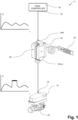
- FIG. 1 shows a highly schematic illustration of an embodiment of an HVAC system 1 comprising an HVAC sensor device 50 arranged between an HVAC controller 20 and an HVAC actuator 10 for actuating an actuated part 40 according to embodiments of the present disclosure.
- the HVAC sensor device 50 is arranged between a control interface 22 of the HVAC controller 20 and a communication interface 18 of the HVAC actuator 10.
- the sensor device 50 comprises a control signal input 54in, a control signal output 54out and an electronic circuit 56.
- the control signal input 54in is configured for receiving control signal(s) for controlling one or more HVAC actuator(s) 10 from an HVAC controller 20.
- the control signal output 54out is configured for transmitting control signal(s) for controlling the HVAC actuator(s) 10.
- the HVAC actuator 10 may comprise various regulating elements, such as - but not limited to - 2, 3 or 6-way valves.
- the regulating elements are pressure independent/ pressure compensated regulating elements.
- the pressure independence/ pressure compensation of the regulating elements is achieved electronically and/or mechanically.
- FIG. 2 shows a highly schematic illustration of a further embodiment of an HVAC system 1 comprising an HVAC sensor device 50 arranged between an HVAC controller 20 and a plurality of HVAC actuators 10, each for actuating respective actuated parts 40 according to embodiments of the present disclosure.
- one HVAC sensor device 50 is configured to pass through, respectively overwrite control signals to a plurality of HVAC actuators 10, each HVAC actuator 10 receiving a different, specific control signal, e.g. by means of a communication bus of the control signals.
- HVAC systems 1 which comprises a 6-way flow regulator 42 capable of switching between a first mode of operation (heating, e.g. at a 90° position of the valve) and a second mode of operation (cooling, e.g. at a 0° position of the valve) based on control signals from the HVAC controller 20.
- the 6-way flow regulator 42 comprises a first fluid input I1; a second fluid input I2; a fluid output O; a fluid return input RI; a first fluid return output RO1; and a second fluid return output RO2.
- the 6-way flow regulator 42 may be operated in a first operating mode, a second operating mode and a third operating mode.
- the 6-way flow regulator 42 In the first operating mode, the 6-way flow regulator 42 enables a flow of fluid from the first fluid input I1 towards the fluid output O and a flow of fluid from the fluid return input RI towards the first fluid return output RO1. In the second operating mode, the 6-way flow regulator 42 enables a flow of fluid from the second fluid input I2 towards the fluid output O and a flow of fluid from the fluid return input Rl towards the second fluid return output RO2. In the third operating mode, the 6-way flow regulator 42 prevents passage of fluid from first fluid input 11 or the second fluid input(I2) to the fluid output O.
- the HVAC sensor device 50 of the present invention ensures that the 6-way flow regulator 42 is switched by the HVAC actuator 10 into a third mode of operation (closed position, e.g. at 45° angle of the valve) under certain environmental conditions, such as condensation and/or relative humidity in the HVAC system, by overwriting the control signals with a control reference value V1 (e.g. 6V), the HVAC actuator 10 being configured to switch the 6-way flow regulator 42 into the third operating mode (closed) upon receipt of the control reference value V1.
- V1 e.g. 6V
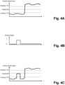
- the sequence of figures 4A to 4C shows the control signal input, the sensor signal indicative of condensation; and the control signal output, respectively, for the HVAC systems 1 of figure 3 .
- Figure 4A shows an illustrative diagram of the control signal received at the control signal input 54in reflecting various operating states, namely cooling, closed and heating.
- Figure 4B shows an illustrative diagram of the sensor signal from the sensor 52 indicative of condensation and/or relative humidity in the HVAC system, shown here with binary values, 0 for lack of and 1 for the presence of condensation and/or a relative humidity above dew point in the HVAC system 1.
- Figure 4C shows an illustrative diagram of the control signal at the control signal output 54out as overwritten by the HVAC sensor device 50 of the present disclosure, wherein for the period when sensor signal(s) indicative of condensation and/or relative humidity is outside the defined range (in the depicted example "1"), the control signal has been overwritten with a control reference value V1 (in the depicted example 6V).
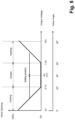
- FIG. 5 shows an illustrative diagram of various operating states of the HVAC system 1 in relation to various values of the control signal.
- various values of the control signal first horizontal axis
- result in corresponding valve angles of the 6-way flow regulator 42 shown on the second horizontal axis.
- the reference value V1 - which is provided by the HVAC sensor device 50 and which is within a value range of the control signal (in the depicted example 6V) - corresponds to a safety position which reduces and/or prevents formation of condensation (a closed position in the depicted example).
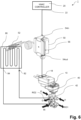
- FIG. 6 shows a highly schematic illustration of a further embodiment of an HVAC system 1 comprising an HVAC sensor device 50 arranged between an HVAC controller 20 and an HVAC actuator for controlling a 6-way flow regulator 42, the 6-way flow regulator being connected to a heat exchanger 80.
- a fluid input side 82 of the heat exchanger 80 is fluidly connected to the fluid output O of the 6-way flow regulator 42 and a fluid return side 84 fluidly connected to the fluid return input Rl of the 6-way flow regulator 42.
- the first fluid input I1 of the 6-way flow regulator 42 is fluidly connected to a fluid source of a first temperature and the second fluid input I2 of the 6-way flow regulator 42 is fluidly connected to a fluid source of a second temperature, the first temperature being different from the second temperature.
- a sensor(s) 52 is communicatively connected to the HVAC sensor device 50 and is arranged to measure condensation on a surface of the heat exchanger 80 and/or a surface of a fluid connection between the heat exchanger 80 and the 6-way flow regulator 42. Additionally, or alternatively, the sensor(s) 52 is arranged to measure the dew-point in a vicinity of the heat exchanger 80.
- FIG. 7 shows a block diagram of an HVAC sensor device 50 according to a first embodiment of the present disclosure, the HVAC sensor device 50 being arranged between an HVAC controller 20 and an HVAC actuator 10 of an HVAC system 1.
- the electronic circuit 56 of the HVAC sensor device 50 comprises a relay switch R configured to connect the control signal input 54in with the control signal output 54out if the sensor signal(s) indicative of condensation and/or relative humidity is within a defined range(s)). If the sensor signal(s) indicative of condensation and/or relative humidity is outside the defined range, the relay switch R connects the control signal output 54out to (a source of) the control reference value V1 (for example in the range of 4.7 - 7.3V).
- FIG. 8 shows a block diagram of an HVAC sensor device 50 according to a further embodiment of the present disclosure, the HVAC sensor device 50 being arranged between an HVAC controller 20 and an HVAC actuator 10 of an HVAC system 1. Illustrated with dotted lines, the sensor device 50 further comprises a feedback output 58out for transmitting feedback signal(s) to the HVAC controller 20.
- the relay switch R of the electronic circuit 56 of the HVAC sensor device 50 connects the feedback output 58out to the feedback input 58in if the sensor signal(s) indicative of condensation and/or relative humidity is within a defined range(s)). If the sensor signal(s) indicative of condensation and/or relative humidity is outside the defined range, in order for the HVAC controller(s) being aware of its control signals being overwritten, the relay switch R connects the feedback output 58out to (a source of) a feedback reference value V2.
- the relay switch R of the electronic circuit 56 of the HVAC sensor device 50 connects the feedback output 58out to a first feedback reference value V2.1 if the sensor signal(s) indicative of condensation and/or relative humidity is within a defined range(s)) and a second feedback reference value V2.2 if the sensor signal(s) indicative of condensation and/or relative humidity is outside the defined range.
- FIG. 9 shows a block diagram of an HVAC sensor device 50 according to an even further embodiment of the present disclosure, the HVAC sensor device 50 being arranged between an HVAC controller 20 and an HVAC actuator 10 of an HVAC system 1, wherein the control reference value V1 and/or the feedback reference value V2 is/ are received by the HVAC sensor device 50 using a reference input(s) 54ref respectively a feedback reference input(s) 58ref.
- the HVAC sensor device 50 is configured to transfer at least a part of electrical power received at the control signal input 54in to the control signal output 54out. Furthermore, the HVAC sensor device 50 is configured to power the electronic circuit 56 and the sensor 52 using electrical power received at the control signal input 54in.
- FIG. 10 shows a block diagram of an HVAC actuator 10 of an HVAC system 1 according to embodiments of the present disclosure.
- the HVAC actuator 10 comprises an electric motor 14 and an electronic circuit 12.
- the electric motor 14 is configured to move an actuated part 40 coupled to the electric motor 14.
- the actuated part 40 is not part of the HVAC actuator 10.
- the HVAC actuator 10 is configured to receive control signal(s).
- the electronic circuit 12 is connected to the electric motor 14 and configured to control the electric motor 14 in accordance with the control signal(s).
- the HVAC actuator 10 is configured to generate feedback signal(s) indicative of an actuated position of the actuated part 40 connected thereto.
- FIG 11 shows an illustrative flowchart of the operation of an HVAC sensor device 50 according to a first embodiment of the present disclosure.
- control signal(s) are received from an HVAC controller 20, at a control signal input 54in of an HVAC sensor device 50.
- the control signals have been generated by an HVAC controller 20 for controlling one or more HVAC actuator(s) 10.
- condensation and/or relative humidity in the HVAC system is measured and sensor signal(s) indicative of condensation and/or relative humidity in the HVAC system is received by an electronic circuit 56 of the HVAC sensor device 50.
- a step S30 the signal(s) indicative of condensation and/or relative humidity in the HVAC system are compared - by the electronic circuit 56 of the HVAC sensor device 50 - with a defined range(s).
- control signal(s) received at the control signal input 54in are passed through - by the electronic circuit 56 of the HVAC sensor device 50 - to the control signal output 54out if the sensor signal(s) indicative of condensation and/or relative humidity is within the defined range(s).
- a step S50 the control signal(s) received at the control signal input 54in are overwritten - by the electronic circuit 56 of the HVAC sensor device 50 - with a control reference value V1 and output at the control signal output 54out if the sensor signal(s) indicative of condensation and/or relative humidity is outside the defined range.
- the HVAC actuator(s) 10 are operated according to the control signals from the HVAC sensor device 50.
- FIG. 12 shows an illustrative flowchart of the operation of an HVAC sensor device 50 according to a further embodiment of the present disclosure, wherein in a step S55, a feedback signal - received at a feedback input 58in of the HVAC sensor device 50 - is overwritten with a feedback reference value V2 and output at a feedback output 58out, if the sensor signal(s) indicative of condensation and/or relative humidity is outside the defined range.
- a first feedback reference value is output at the feedback output 58out, if the sensor signal(s) indicative of condensation and/or relative humidity is within the defined range.
- HVAC actuator 10 electronic circuit (of HVAC actuator) 12 electric motor 14 communication interface (of HVAC actuator) 18 HVAC controller 20 control interface (of HVAC controller) 22 actuated part 40 6-way flow regulator 42 a first fluid input (of 6-way flow regulator) 11 a second fluid input (of 6-way flow regulator) I2 a fluid output (of 6-way flow regulator) O a fluid return input (of 6-way flow regulator) Rl a first fluid return output (of 6-way flow regulator) RO1 a second fluid return output (of 6-way flow regulator) RO2 sensor device 50 sensor 52 control signal input 54in control signal output 54out reference input(s) 54ref electronic circuit (of sensor device) 56 relay switch R feedback signal input 58in feedback signal output 58out feedback reference input(s) 58ref control reference value V1 feedback reference value V2 heat exchanger 80 fluid input side (of heat exchanger) 82 fluid return side (of heat exchanger) 84
Landscapes
- Engineering & Computer Science (AREA)
- Chemical & Material Sciences (AREA)
- Combustion & Propulsion (AREA)
- Mechanical Engineering (AREA)
- General Engineering & Computer Science (AREA)
- Human Computer Interaction (AREA)
- Air Conditioning Control Device (AREA)
Description
- The present invention relates to a Heating, Ventilating and Air Conditioning HVAC sensor device. The present invention further relates to an HVAC system comprising one or more HVAC sensor devices, a controller device and one or more HVAC actuators configured to actuate one or more actuated parts. The present invention further relates to a method of operating an HVAC system.
- In the field of Heating, Ventilating and Air Conditioning, HVAC systems typically comprise a fluid transportation system connected to a heat exchanger arranged such as to be able to transfer thermal energy to or from the environment by means of a fluid circulating in said fluid transportation system.
- In order to be able to regulate the flow of fluid to/ from the heat exchanger, the heat exchanger is connected to the fluid transportation system via one or more actuated parts, such as valves and dampers. The actuated parts are mechanically controlled by HVAC actuators, including motorized HVAC actuators coupled to the actuated part. In the field of HVAC, HVAC actuators typically comprise an electric motor, coupled (through gears and/or other mechanical coupling), to the actuated part.
- HVAC systems commonly comprise an HVAC controller configured to generate control signal(s) for operating the HVAC actuator(s). In typical HVAC applications, the HVAC controller(s) generate the control signals for the HVAC actuators according to various control algorithms (e.g. with regards to differential pressure, room temperature, flow of energy, etc.) to thereby actuate the actuators, such as to open and close an orifice of a valve or damper to regulate the flow of fluid to and from heat exchanger(s).
- It is an important aspect in the field of Heating, Ventilating and Air Conditioning HVAC to operate the HVAC system in view of environmental variable(s) of the environment the HVAC system is installed in. Such environmental variables are measured by corresponding sensors arranged in the controlled environment, for example in the proximity of the heat exchanger(s) and/or the fluid transportation system to/from such heat exchanger(s). In particular, condensation management is an important aspect in the field of Heating, Ventilating and Air Conditioning HVAC to prevent discomfort, damage or improper operation due to condensation on components of the HVAC system and/or surfaces of the environment where the HVAC system is installed.
- A known method for operating an HVAC system in view of environmental variable(s) is to communicatively connect sensors for the measurement of environmental variables to the HVAC controller(s) and to configure the HVAC controller(s) to generate the control signal(s) for operating the HVAC actuator(s) considering sensor signal(s) indicative of the one or more environmental variable(s).
-
US 2008/0078842 describes a humidity control system integrated into an air processing system that adjusts the operation of a compressor and blower based on relative humidity levels, optimizing dehumidification and air quality effectiveness while preventing re-evaporation of condensed moisture during compressor off cycles. The system uses various sensors, controls, and a manual selector to manage humidity independent of temperature demands. -
AU2016100873A4 - U.S. Patent Application
US 2021/0010683 describes a water regulation system for buildings, comprising a main control panel, peripheral units with sensors and user interfaces, and a series of valves, which communicate to control water distribution and prevent leaks through real-time detection of occupancy, moisture, and user inputs allowing for rapid manual override to shut off water flow. - However, there are certain use cases when communicatively connecting the sensors arranged in the controlled environment (in the proximity of the heat exchanger(s) and/or the fluid transportation system) is not possible, disadvantageous and/or economically/ logistically not preferred.
- A first use case, when communicatively connecting the sensors of environmental variables to the HVAC controller(s) is not desirable - is related to upgrading/retrofitting of installations not provided with sensors of environmental variables.
- A further use case, when communicatively connecting the sensors of environmental variables to the HVAC controller(s) is not desirable - is when HVAC controller(s) of an HVAC system are not suitable and/or not configured to be connected to such sensors and/or not configured to process signals of such sensors.
- An even further use case, when communicatively connecting the sensors of environmental variables to the HVAC controller(s) is not desirable - is when there is a significant distance between the controlled environment (where the sensors are to be located) and the HVAC controller(s). In such use cases, providing a data communication between the HVAC controllers and the sensors of environmental variables might require additional wiring infrastructure and/or additional radio communication equipment being installed, both of which might not be logistically or economically feasible. Furthermore, additional radio communication equipment might not even be possible, for example in environments where radio communication is to be reduced to a minimum due to sensitive equipment or due to security/privacy concerns.
- It is an object of embodiments disclosed herein to provide a solution that - at least partially - addresses the above-identified use-cases, providing a feasible solution to operate an HVAC system in view of environmental variable(s).
- In particular, it is an object of embodiments disclosed herein to provide a solution that enables operation of an HVAC systems in view of condensation in the HVAC system which overcomes at least a part of the disadvantages of known solutions which rely on communicative connection(s) from sensors located in a proximity of HVAC devices to HVAC controller(s).
- In particular, it is a further object of embodiments disclosed herein to provide a retrofit solution to existing HVAC systems that enables operation of the retrofitted HVAC system in view of condensation in the HVAC system, without the need to exchange/ adapt/ or even reprogram existing HVAC controller(s) not configured to operate in view of the respective environmental variable.
- According to embodiments of the present disclosure, this object is addressed by an HVAC sensor device to be arranged between an HVAC controller and an HVAC actuator, in particular between a control interface of the HVAC controller and a communication interface of the HVAC actuator. The sensor device comprises a control signal input, a control signal output and an electronic circuit. The control signal input is configured for receiving control signal(s) for controlling one or more HVAC actuator(s) from an HVAC controller. The control signal output is configured for transmitting control signal(s) for controlling the HVAC actuator(s) to the HVAC actuator(s).
- The electronic circuit is configured to receive a sensor signal(s) indicative of condensation and/or relative humidity in the HVAC system. The electronic circuit then compares the sensor signal(s) indicative of condensation and/or relative humidity in the HVAC system with respective defined range(s).
- The electronic circuit is further configured to pass through (unaltered) the control signal(s) received at the control signal input to the control signal output if the sensor signal(s) indicative of condensation and/or relative humidity is within a defined range(s).
- The electronic circuit is further configured to overwrite the control signal(s) received at the control signal input with a control reference value and output the overwritten control signal(s) at the control signal output if the sensor signal(s) indicative of condensation and/or relative humidity is outside the defined range.
- According to embodiments of the present disclosure, this object is further addressed by a method of operating an HVAC system comprising the steps of: receiving from an HVAC controller, at a control signal input of an HVAC sensor device, of control signal(s) for controlling one or more HVAC actuator(s); receiving, by an electronic circuit of the HVAC sensor device, of sensor signal(s) indicative of condensation and/or relative humidity in the HVAC system; comparing the signal(s) indicative of condensation and/or relative humidity in the HVAC system with a defined range(s); passing through the control signal(s) received at the control signal input to the control signal output if the sensor signal(s) indicative of condensation and/or relative humidity is within the defined range(s); and overwriting the control signal(s) received at the control signal input with a control reference value and output the overwritten control signal(s) at the control signal output if the sensor signal(s) indicative of condensation and/or relative humidity is outside the defined range.
- Embodiments according to the present disclosure are advantageous since the sensor device may be placed in the proximity of the HVAC actuators, hence communicative connections to the HVAC controller(s) unnecessary. Furthermore, embodiments according to the present disclosure are advantageous since the sensor devices may easily be provided to retrofit existing HVAC systems, by arranging the sensor devices between existing HVAC controller(s) and existing HVAC actuator(s) without the need to alter or even re-program any of these. Thereby, the functionality of existing HVAC systems may be extended in an effort- and cost-efficient manner by enabling the HVAC system to operate in view of environmental variables, such as condensation and/or relative humidity, which the HVAC system was not originally (before the retrofit according to embodiments of the present disclosure) able to consider.
- According to embodiments of the present disclosure, one or more sensor(s) for the measurement of condensation and/or relative humidity in the HVAC system are comprised by or communicatively connected to the sensor device.
- According to particular embodiments of the present disclosure, the sensor signal(s) is indicative of:
- condensation on a surface of a heat exchanger (80) fluidly connected to the one or more HVAC actuator(s) (10) and/or
- condensation on a surface of a fluid connection to or from the one or more HVAC actuator(s) (10); and/or
- temperature and relative humidity of a volume of air in the HVAC system (1) in order to detect whether the volume of air has reached its dew point.
- It is a further object of particular embodiments disclosed herein to provide a solution that enables HVAC controller(s) to be aware of its control signals (to the HVAC actuator(s)) being overwritten - by sensor device(s) of the present disclosure. This further objective is addressed according to embodiments of the present disclosure in that the HVAC sensor device further comprises a feedback output for transmitting feedback signal(s) to the HVAC controller, wherein the electronic circuit is further configured to output a feedback reference value at the feedback output if the sensor signal(s) indicative of condensation and/or relative humidity is outside the defined range. This further objective is further addressed according to embodiments of the present disclosure in that the method of operating an HVAC system further comprises transmitting, at a feedback output of the HVAC sensor device, a feedback reference value to the HVAC controller if the sensor signal(s) indicative of condensation and/or relative humidity is outside the defined range.
- It is a further object of particular embodiments disclosed herein to provide a solution that enables feedback signals generated by HVAC actuators to be available to HVAC controller(s) under normal operating conditions - that is when the control signals are not overwritten by the sensor device(s) of the present disclosure. This further objective is addressed according to embodiments of the present disclosure in that the HVAC sensor device further comprises a feedback input for receiving feedback signal(s) from the HVAC actuator(s), wherein the electronic circuit is further configured to pass through the feedback signal(s) received at the feedback input to the feedback output if the sensor signal(s) indicative of condensation and/or relative humidity is within a defined range(s). This further objective is further addressed according to embodiments of the present disclosure in that the method of operating an HVAC system further comprises receiving a feedback signal(s) from the HVAC actuator(s) at a feedback input of the HVAC sensor device; and passing through the feedback signal(s) received at the feedback input to the feedback output if the sensor signal(s) indicative of condensation and/or relative humidity is within a defined range(s).
- By passing-through, respectively overwriting feedback signals from HVAC actuator(s) to the HVAC controller(s), the sensor device of the present disclosure enables transmission of feedback signals, which are indicative of condensation and/or relative humidity in the HVAC system being outside the defined range, using pre-existing feedback channels. Hence, the functionality of existing HVAC systems may be further extended without the need for additional connections (wired or wireless) between the HVAC actuator(s) and HVAC controller(s).
- According to embodiments of the present disclosure, the control reference value and/or the feedback reference value is/are received by the HVAC sensor device using a reference input(s) respectively a feedback reference input(s).
- Alternatively, or additionally - in order to reduce complexity, the electric circuit is further configured to derive the control reference value and/or the feedback reference value from the control signal(s) received at the control signal input. According to embodiments of the present disclosure, the control reference value is within a value range of the control signal.
- It is a further object of particular embodiments disclosed herein to provide a solution that enables HVAC controller(s) to be aware of the values of condensation and/or relative humidity in the HVAC system as measured by the sensor device(s) of the present disclosure. This further objective is addressed according to embodiments of the present disclosure in that the HVAC sensor device further comprises a sensor signal output for transmitting the sensor signal(s) indicative of condensation and/or relative humidity in the HVAC system to the HVAC controller, wherein the electronic circuit is further configured to forward the sensor signal(s) at said sensor signal output. This further objective is further addressed according to embodiments of the present disclosure in that the method of operating an HVAC system further comprises forwarding, at a sensor signal output, the sensor signal(s) indicative of condensation and/or relative humidity in the HVAC system to the HVAC controller.
- According to embodiments of the present disclosure, the control signal(s) is/are analogue signal(s), wherein the control reference value and/or the feedback reference value are predetermined voltage/current values.
- According to embodiments of the present disclosure, the control signal(s) is/are digital signal(s), wherein the control reference value and/or the feedback reference value are predetermined digital values.
- It is a further object of particular embodiments disclosed herein to provide a solution that ensures that the actuated part is moved into a safety position which reduces and/or prevents formation of condensation, such as a closed position of a valve under certain environmental conditions, such as condensation and/or relative humidity in the HVAC system,. This further objective is addressed according to embodiments of the present disclosure in that HVAC sensor device is configured such as to overwrite the control signal(s) with a control reference value, which - when received by the actuator(s) - causes the HVAC actuator(s) to move an actuated part in a safety position which reduces and/or prevents formation of condensation, wherein the control reference value is within a value range of the control signal.
- It is a further object of particular embodiments disclosed herein to provide a solution that allows extending the functionality of HVAC systems to operate in view of condensation and/or relative humidity within the HVAC system while minimizing the needs for electrical installation. According to embodiments of the present disclosure this further object is addressed in that the HVAC sensor device is configured to transfer at least a part of electrical power received at the control signal input to the control signal output and to power the electronic circuit using electrical power received at the control signal input. Additionally, the sensor device may be further configured to also power a sensor (for the measurement of condensation and/or relative humidity in the HVAC system) using at least a part of the electrical power received at the control signal input. This further objective is also addressed according to embodiments of the present disclosure in that the method of operating an HVAC system further comprises transferring at least a part of electrical power received at the control signal input to the control signal output and powering the electronic circuit of the HVAC sensor device and/or sensor(s) for the measurement of condensation and/or relative humidity in the HVAC system using at least a part of the electrical power received at the control signal input.
- It is a further object of particular embodiments disclosed herein to provide an HVAC system operating in view of condensation and/or relative humidity in the HVAC system overcoming at least a part of the disadvantages of known solutions.
- The above-identified objective is further addressed by an HVAC system comprising an HVAC controller, one or more HVAC actuator(s) and an HVAC sensor device according to one of the embodiments disclosed herein. The HVAC controller of the HVAC system is configured to generate control signal(s) for operating one or more HVAC actuator(s) at a control interface. The one or more HVAC actuator(s) comprise an electric motor configured to move an actuated part coupled to the electric motor, an electronic circuit connected to the electric motor, and a communication interface connected to the electronic circuit. The electronic circuit of the HVAC actuator(s) is configured to control the electric motor in accordance with control signals received via the communication interface.
- The HVAC sensor device is arranged between the control interface of the HVAC controller and the communication interface of the HVAC actuator. The wording "arranged between the control interface of the HVAC controller and the communication interface of the HVAC actuator" is to be understood to relate to being arranged in the communication path between the control interface of the HVAC controller and the communication interface of the HVAC actuator.
- A known particular application of HVAC systems comprises a 6-way flow regulator arranged between a heat exchanger and a fluid source of a first temperature and a fluid source of a second temperature. In particular, 6-way flow regulators are used in applications when the same heat exchanger is being used for both heating and cooling, the 6-way flow regulator being arranged to switch the heat exchanger's fluid input and return between a first respectively a second fluid circuit. 6-way flow regulators comprise a first fluid input; a second fluid input; a fluid output; a fluid return input; a first fluid return output; and a second fluid return output. Known 6-way flow regulators may be operated in a first operating mode, a second operating mode and a third operating mode. In the first operating mode, the 6-way flow regulator enables a flow of fluid from the first fluid input towards the fluid output and a flow of fluid from the fluid return input towards the first fluid return output. In the second operating mode, the 6-way flow regulator enables a flow of fluid from the second fluid input towards the fluid output and a flow of fluid from the fluid return input towards the second fluid return output. In the third operating mode, the 6-way flow regulator prevents passage of fluid between any of the first fluid input; the second fluid input(l2); the fluid output; the fluid return input; the first fluid return output and the second fluid return output.
- It is an object of further embodiments of the present invention to enable an HVAC system comprising a 6-way flow regulatorto operate in view of environmental conditions, such as condensation and/or relative humidity in the HVAC system, while avoiding at least part of the disadvantages associated with known solutions. According to embodiments of the present disclosure this further objective is addressed by an HVAC system having a 6-way flow regulator; an HVAC controller configured to generate control signal(s) for operating one or more HVAC actuator(s); and an HVAC sensor device according to one of the embodiment disclosed herein, wherein the HVAC actuator is configured to switch the 6-way flow regulator into the third operating mode upon receipt of the control reference value.
- According to further embodiments, the HVAC system according to the present disclosure further comprises a heat exchanger and a sensor. A fluid input side of the heat exchanger is fluidly connected to the fluid output of the 6-way flow regulator and a fluid return side fluidly connected to the fluid return input of the 6-way flow regulator. The first fluid input of the 6-way flow regulator is fluidly connected to a fluid source of a first temperature and the second fluid input of the 6-way flow regulator is fluidly connected to a fluid source of a second temperature, the first temperature being different from the second temperature. The sensor(s) is arranged to measure condensation on a surface of the heat exchanger and/or a fluid connection between the heat exchanger and the 6-way flow regulator. Additionally, or alternatively, the sensor(s) is arranged to measure the dew-point in a vicinity of the heat exchanger.
- It is to be understood that both the foregoing general description and the following detailed description present embodiments, and are intended to provide an overview or framework for understanding the nature and character of the disclosure. The accompanying drawings are included to provide a further understanding, and are incorporated into and constitute a part of this specification. The drawings illustrate various embodiments, and together with the description serve to explain the principles and operation of the concepts disclosed.
- The herein described disclosure will be more fully understood from the detailed description given herein below and the accompanying drawings which should not be considered limiting to the disclosure described in the appended claims. The drawings which show:
- Figure 1:
- a highly schematic illustration of an embodiment of an HVAC system comprising an HVAC sensor device arranged between an HVAC controller and an actuator for actuating an actuated part according to embodiments of the present disclosure;
- Figure 2:
- a highly schematic illustration of a further embodiment of an HVAC system comprising an HVAC sensor device arranged between an HVAC controller and a plurality of HVAC actuators, each for actuating respective actuated parts according to embodiments of the present disclosure;
- Figure 3:
- a highly schematic illustration of a further embodiment of an HVAC system comprising an HVAC sensor device arranged between an HVAC controller and an HVAC actuator for controlling a 6-way flow regulator according to embodiments of the present disclosure;
- Figure 4A:
- an illustrative diagram showing the control signal received at the control signal input;
- Figure 4B:
- an illustrative diagram showing the sensor signal indicative of condensation in the HVAC system;
- Figure 4C:
- an illustrative diagram showing the control signal at the control signal output;
- Figure 5:
- an illustrative diagram showing various operating states of an HVAC system in relation to various values of the control signal;
- Figure 6:
- a highly schematic illustration of a further embodiment of an HVAC system comprising an HVAC sensor device arranged between an HVAC controller and an HVAC actuator for controlling a 6-way flow regulator according to embodiments of the present disclosure, the 6-way flow regulator being connected to a heat exchanger;
- Figure 7:
- a block diagram of an HVAC sensor device according to an embodiment of the present disclosure, the HVAC sensor device being arranged between an HVAC controller and an actuator of an HVAC system;
- Figure 8:
- a block diagram of an HVAC sensor device according to a further embodiment of the present disclosure, the HVAC sensor device being arranged between an HVAC controller and an actuator of an HVAC system;
- Figure 9:
- a block diagram of an HVAC sensor device according to an even further embodiment of the present disclosure, the HVAC sensor device being arranged between an HVAC controller and an actuator of an HVAC system;
- Figure 10:
- a block diagram of an HVAC actuator of an HVAC system according to the present disclosure;
- Figure 11:
- an illustrative flowchart of the operation of an HVAC sensor device according to a first embodiment of the present disclosure; and
- Figure 12:
- an illustrative flowchart of the operation of an HVAC sensor device according to a further embodiment of the present disclosure.
- Reference will now be made in detail to certain embodiments, examples of which are illustrated in the accompanying drawings, in which some, but not all features are shown. Indeed, embodiments disclosed herein may be embodied in many different forms and should not be construed as limited to the embodiments set forth herein; rather, these embodiments are provided so that this disclosure will satisfy applicable legal requirements. Whenever possible, like reference numbers will be used to refer to like components or parts.
-
Figure 1 shows a highly schematic illustration of an embodiment of anHVAC system 1 comprising anHVAC sensor device 50 arranged between anHVAC controller 20 and anHVAC actuator 10 for actuating an actuatedpart 40 according to embodiments of the present disclosure. As illustrated, theHVAC sensor device 50 is arranged between acontrol interface 22 of theHVAC controller 20 and acommunication interface 18 of theHVAC actuator 10. Thesensor device 50 comprises a control signal input 54in, a control signal output 54out and anelectronic circuit 56. The control signal input 54in is configured for receiving control signal(s) for controlling one or more HVAC actuator(s) 10 from anHVAC controller 20. The control signal output 54out is configured for transmitting control signal(s) for controlling the HVAC actuator(s) 10. TheHVAC actuator 10 may comprise various regulating elements, such as - but not limited to - 2, 3 or 6-way valves. According to particular embodiments disclosed herein, the regulating elements are pressure independent/ pressure compensated regulating elements. According to embodiments of the present disclosure, the pressure independence/ pressure compensation of the regulating elements is achieved electronically and/or mechanically. -
Figure 2 shows a highly schematic illustration of a further embodiment of anHVAC system 1 comprising anHVAC sensor device 50 arranged between anHVAC controller 20 and a plurality ofHVAC actuators 10, each for actuating respective actuatedparts 40 according to embodiments of the present disclosure. According to embodiments of the present disclosure, oneHVAC sensor device 50 is configured to pass through, respectively overwrite control signals to a plurality ofHVAC actuators 10, eachHVAC actuator 10 receiving a different, specific control signal, e.g. by means of a communication bus of the control signals. - Turning now to
Figure 3 , a particular application ofHVAC systems 1 shall be described which comprises a 6-way flow regulator 42 capable of switching between a first mode of operation (heating, e.g. at a 90° position of the valve) and a second mode of operation (cooling, e.g. at a 0° position of the valve) based on control signals from theHVAC controller 20. As illustrated, the 6-way flow regulator 42 comprises a first fluid input I1; a second fluid input I2; a fluid output O; a fluid return input RI; a first fluid return output RO1; and a second fluid return output RO2. The 6-way flow regulator 42 may be operated in a first operating mode, a second operating mode and a third operating mode. In the first operating mode, the 6-way flow regulator 42 enables a flow of fluid from the first fluid input I1 towards the fluid output O and a flow of fluid from the fluid return input RI towards the first fluid return output RO1. In the second operating mode, the 6-way flow regulator 42 enables a flow of fluid from the second fluid input I2 towards the fluid output O and a flow of fluid from the fluid return input Rl towards the second fluid return output RO2. In the third operating mode, the 6-way flow regulator 42 prevents passage of fluid from firstfluid input 11 or the second fluid input(I2) to the fluid output O. - The
HVAC sensor device 50 of the present invention ensures that the 6-way flow regulator 42 is switched by theHVAC actuator 10 into a third mode of operation (closed position, e.g. at 45° angle of the valve) under certain environmental conditions, such as condensation and/or relative humidity in the HVAC system, by overwriting the control signals with a control reference value V1 (e.g. 6V), theHVAC actuator 10 being configured to switch the 6-way flow regulator 42 into the third operating mode (closed) upon receipt of the control reference value V1. - The sequence of
figures 4A to 4C shows the control signal input, the sensor signal indicative of condensation; and the control signal output, respectively, for theHVAC systems 1 offigure 3 . -
Figure 4A shows an illustrative diagram of the control signal received at the control signal input 54in reflecting various operating states, namely cooling, closed and heating. -
Figure 4B shows an illustrative diagram of the sensor signal from thesensor 52 indicative of condensation and/or relative humidity in the HVAC system, shown here with binary values, 0 for lack of and 1 for the presence of condensation and/or a relative humidity above dew point in theHVAC system 1. -
Figure 4C shows an illustrative diagram of the control signal at the control signal output 54out as overwritten by theHVAC sensor device 50 of the present disclosure, wherein for the period when sensor signal(s) indicative of condensation and/or relative humidity is outside the defined range (in the depicted example "1"), the control signal has been overwritten with a control reference value V1 (in the depicted example 6V). -
Figure 5 shows an illustrative diagram of various operating states of theHVAC system 1 in relation to various values of the control signal. As depicted, various values of the control signal (first horizontal axis) result in corresponding valve angles of the 6-way flow regulator 42 (shown on the second horizontal axis). In particular, the reference value V1 - which is provided by theHVAC sensor device 50 and which is within a value range of the control signal (in the depicted example 6V) - corresponds to a safety position which reduces and/or prevents formation of condensation (a closed position in the depicted example). -
Figure 6 shows a highly schematic illustration of a further embodiment of anHVAC system 1 comprising anHVAC sensor device 50 arranged between anHVAC controller 20 and an HVAC actuator for controlling a 6-way flow regulator 42, the 6-way flow regulator being connected to aheat exchanger 80. In order for thesame heat exchanger 80 to be used for both heating and cooling, afluid input side 82 of theheat exchanger 80 is fluidly connected to the fluid output O of the 6-way flow regulator 42 and afluid return side 84 fluidly connected to the fluid return input Rl of the 6-way flow regulator 42. The first fluid input I1 of the 6-way flow regulator 42 is fluidly connected to a fluid source of a first temperature and the second fluid input I2 of the 6-way flow regulator 42 is fluidly connected to a fluid source of a second temperature, the first temperature being different from the second temperature. A sensor(s) 52 is communicatively connected to theHVAC sensor device 50 and is arranged to measure condensation on a surface of theheat exchanger 80 and/or a surface of a fluid connection between theheat exchanger 80 and the 6-way flow regulator 42. Additionally, or alternatively, the sensor(s) 52 is arranged to measure the dew-point in a vicinity of theheat exchanger 80. -
Figure 7 shows a block diagram of anHVAC sensor device 50 according to a first embodiment of the present disclosure, theHVAC sensor device 50 being arranged between anHVAC controller 20 and anHVAC actuator 10 of anHVAC system 1. As illustrated, theelectronic circuit 56 of theHVAC sensor device 50 comprises a relay switch R configured to connect the control signal input 54in with the control signal output 54out if the sensor signal(s) indicative of condensation and/or relative humidity is within a defined range(s)). If the sensor signal(s) indicative of condensation and/or relative humidity is outside the defined range, the relay switch R connects the control signal output 54out to (a source of) the control reference value V1 (for example in the range of 4.7 - 7.3V). -
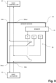
Figure 8 shows a block diagram of anHVAC sensor device 50 according to a further embodiment of the present disclosure, theHVAC sensor device 50 being arranged between anHVAC controller 20 and anHVAC actuator 10 of anHVAC system 1. Illustrated with dotted lines, thesensor device 50 further comprises a feedback output 58out for transmitting feedback signal(s) to theHVAC controller 20. - As illustrated, the relay switch R of the
electronic circuit 56 of theHVAC sensor device 50 connects the feedback output 58out to the feedback input 58in if the sensor signal(s) indicative of condensation and/or relative humidity is within a defined range(s)). If the sensor signal(s) indicative of condensation and/or relative humidity is outside the defined range, in order for the HVAC controller(s) being aware of its control signals being overwritten, the relay switch R connects the feedback output 58out to (a source of) a feedback reference value V2. Alternatively, the relay switch R of theelectronic circuit 56 of theHVAC sensor device 50 connects the feedback output 58out to a first feedback reference value V2.1 if the sensor signal(s) indicative of condensation and/or relative humidity is within a defined range(s)) and a second feedback reference value V2.2 if the sensor signal(s) indicative of condensation and/or relative humidity is outside the defined range. -
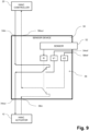
Figure 9 shows a block diagram of anHVAC sensor device 50 according to an even further embodiment of the present disclosure, theHVAC sensor device 50 being arranged between anHVAC controller 20 and anHVAC actuator 10 of anHVAC system 1, wherein the control reference value V1 and/or the feedback reference value V2 is/ are received by theHVAC sensor device 50 using a reference input(s) 54ref respectively a feedback reference input(s) 58ref. - According to embodiments disclosed herein, the
HVAC sensor device 50 is configured to transfer at least a part of electrical power received at the control signal input 54in to the control signal output 54out. Furthermore, theHVAC sensor device 50 is configured to power theelectronic circuit 56 and thesensor 52 using electrical power received at the control signal input 54in. -
Figure 10 shows a block diagram of anHVAC actuator 10 of anHVAC system 1 according to embodiments of the present disclosure. As illustrated, theHVAC actuator 10 comprises anelectric motor 14 and anelectronic circuit 12. Theelectric motor 14 is configured to move an actuatedpart 40 coupled to theelectric motor 14. The actuatedpart 40 is not part of theHVAC actuator 10. TheHVAC actuator 10 is configured to receive control signal(s). Theelectronic circuit 12 is connected to theelectric motor 14 and configured to control theelectric motor 14 in accordance with the control signal(s). According to embodiments of the present disclosure, theHVAC actuator 10 is configured to generate feedback signal(s) indicative of an actuated position of the actuatedpart 40 connected thereto. -
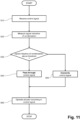
Figure 11 shows an illustrative flowchart of the operation of anHVAC sensor device 50 according to a first embodiment of the present disclosure. In a step S10, control signal(s) are received from anHVAC controller 20, at a control signal input 54in of anHVAC sensor device 50. The control signals have been generated by anHVAC controller 20 for controlling one or more HVAC actuator(s) 10. - In a step S20 condensation and/or relative humidity in the HVAC system is measured and sensor signal(s) indicative of condensation and/or relative humidity in the HVAC system is received by an
electronic circuit 56 of theHVAC sensor device 50. - In a step S30, the signal(s) indicative of condensation and/or relative humidity in the HVAC system are compared - by the
electronic circuit 56 of the HVAC sensor device 50 - with a defined range(s). - In a step S40, the control signal(s) received at the control signal input 54in are passed through - by the
electronic circuit 56 of the HVAC sensor device 50 - to the control signal output 54out if the sensor signal(s) indicative of condensation and/or relative humidity is within the defined range(s). - In a step S50, the control signal(s) received at the control signal input 54in are overwritten - by the
electronic circuit 56 of the HVAC sensor device 50 - with a control reference value V1 and output at the control signal output 54out if the sensor signal(s) indicative of condensation and/or relative humidity is outside the defined range. - In a step S60,the HVAC actuator(s) 10 are operated according to the control signals from the
HVAC sensor device 50. -
Figure 12 shows an illustrative flowchart of the operation of anHVAC sensor device 50 according to a further embodiment of the present disclosure, wherein in a step S55, a feedback signal - received at a feedback input 58in of the HVAC sensor device 50 - is overwritten with a feedback reference value V2 and output at a feedback output 58out, if the sensor signal(s) indicative of condensation and/or relative humidity is outside the defined range. According to embodiments of the present disclosure, in the absence of a feedback signal, a first feedback reference value is output at the feedback output 58out, if the sensor signal(s) indicative of condensation and/or relative humidity is within the defined range.List of reference numerals HVAC actuator 10 electronic circuit (of HVAC actuator) 12 electric motor 14 communication interface (of HVAC actuator) 18 HVAC controller 20 control interface (of HVAC controller) 22 actuated part 40 6-way flow regulator 42 a first fluid input (of 6-way flow regulator) 11 a second fluid input (of 6-way flow regulator) I2 a fluid output (of 6-way flow regulator) O a fluid return input (of 6-way flow regulator) Rl a first fluid return output (of 6-way flow regulator) RO1 a second fluid return output (of 6-way flow regulator) RO2 sensor device 50 sensor 52 control signal input 54in control signal output 54out reference input(s) 54ref electronic circuit (of sensor device) 56 relay switch R feedback signal input 58in feedback signal output 58out feedback reference input(s) 58ref control reference value V1 feedback reference value V2 heat exchanger 80 fluid input side (of heat exchanger) 82 fluid return side (of heat exchanger) 84
Claims (18)
- An HVAC sensor device (50) comprising:- a control signal input (54in) configured to receive, from an HVAC controller (20), control signal(s) for controlling one or more HVAC actuator(s) (10) of an HVAC system (1);- a control signal output (54out) configured to transmit control signal(s) to the HVAC actuator(s) (10); and- an electronic circuit (56) configured to:- receive a sensor signal(s) indicative of condensation and/or relative humidity in the HVAC system;- pass through the control signal(s) received at the control signal input (54in) to the control signal output (54out) if the sensor signal(s) indicative of condensation and/or relative humidity is within a defined range(s); and- overwrite the control signal(s) received at the control signal input (54in) with a control reference value (V1) and output the overwritten control signal(s) at the control signal output (54out) if the sensor signal(s) indicative of condensation and/or relative humidity is outside the defined range, which control reference value (V1) - when received by the actuator(s) (10) - causes the HVAC actuator(s) (10) to move an actuated part (40) to a safety position which reduces and/or prevents formation of condensation , wherein the control reference value (V1) is within a value range of the control signal.
- The HVAC sensor device (50) according to claim 1, wherein the electric circuit (56) is further configured to derive the control reference value (V1) from the control signal(s) received at the control signal input (54in).
- The HVAC sensor device (50) according to claim 1 or 2, wherein the sensor signal(s) is indicative of:- condensation on a surface of a heat exchanger (80) fluidly connected to the one or more HVAC actuator(s) (10) and/or- condensation on a surface of a fluid connection to or from the one or more HVAC actuator(s) (10); and/or- a temperature and a relative humidity of a volume of air in the HVAC system (1) in order to detect whether the volume of air has reached its dew point.
- The HVAC sensor device (50) according to one of the claims 1 to 3, further comprising a reference input(s) (54ref) for receiving the control reference value (V1).
- The HVAC sensor device (50) according to one of the claims 1 to 4, further comprising a feedback output (58out) for transmitting feedback signal(s) to the HVAC controller (20),
wherein the electronic circuit (56) is further configured to output a feedback reference value (V2) at the feedback output (58out) if the sensor signal(s) indicative of condensation and/or relative humidity is outside the defined range. - The HVAC sensor device (50) according to claim 5, further comprising a feedback input (58in) for receiving feedback signal(s) from the HVAC actuator(s) (10), wherein the electronic circuit (56) is further configured to pass through the feedback signal(s) received at the feedback input (58in) to the feedback output (58out) if the sensor signal(s) indicative of condensation and/or relative humidity is within a defined range(s).
- The HVAC sensor device (50) according to claim 5 or 6, further comprising a feedback reference input(s) (58ref) for receiving the feedback reference value (V2).
- The HVAC sensor device (50) according to one of the claims 1 to 7, further comprising one or more sensor(s) (52) for the measurement of condensation on a surface of a heat exchanger (80) fluidly connected to the one or more HVAC actuator(s) (10) and/or on a surface of a fluid connection to or from the one or more HVAC actuator(s) (10) and/or one or more sensor(s) (52) for the measurement of relative humidity of a volume of air in the HVAC system (1) in order to detect whether the volume of air has reached its dew point.
- The HVAC sensor device (50) according to one of the claims 1 to 8, further configured to:- transfer at least a part of electrical power received at the control signal input (54in) to the control signal output (54out); and/or- power the electronic circuit (56) and/or sensor(s) (52) for the measurement of condensation and/or relative humidity using at least a part of the electrical power received at the control signal input (54in).
- An HVAC system (1) comprising:- an HVAC controller (20) configured to generate control signal(s) for operating one or more HVAC actuator(s) (10) at a control interface (22);- one or more HVAC actuator(s) (10) having:- an electric motor (20) configured to move an actuated part (40) coupled to the electric motor (20);- an electronic circuit (12) connected to the electric motor (20); and- a communication interface (18) connected to the electronic circuit (12); the electronic circuit (1 2) of the HVAC actuator (10) being configured to control the electric motor (20) in accordance with control signals received via the communication interface (18); and- an HVAC sensor device (50) according to one of the claims 1 to 9, the HVAC sensor device (50) being arranged between the control interface (22) of the HVAC controller (20) and the communication interface (18) of the HVAC actuator (10).
- The HVAC system (1) according to claim 10, wherein the actuated part (40) comprises a 6-way flow regulator (42) comprising:- a first fluid input (I1);- a second fluid input (I2);- a fluid output (O);- a fluid return input (RI);- a first fluid return output (RO1); and- a second fluid return output (RO2),wherein the HVAC actuator(s) (10) is configured to switch the 6-way flow regulator (42) between a first operating mode, a second operating mode and a third operating mode:wherein, in the first operating mode, the 6-way flow regulator (42) enables:- a flow of fluid from the first fluid input (I1) towards the fluid output (O); and- a flow of fluid from the fluid return input (RI) towards the first fluid return output (RO1),wherein, in the second operating mode, the 6-way flow regulator (42) enables:- a flow of fluid from the second fluid input (I2) towards the fluid output (O); and- a flow of fluid from the fluid return input (RI) towards the second fluid return output (RO2),wherein, in the third operating mode, the 6-way flow regulator (42) prevents passage of fluid between any of the first fluid input (I1); the second fluid input(I2); the fluid output (O); the fluid return input (RI); the first fluid return output (RO1) and the second fluid return output (RO2), andwherein the HVAC actuator (10) is configured to switch the 6-way flow regulator (42) into the third operating mode upon receipt of the control reference value (V1).
- The HVAC system (1) according to claim 11, further comprising:- a heat exchanger (80) having a fluid input side (82) fluidly connected to the fluid output (O) of the 6-way flow regulator (42) and a fluid return side (84) fluidly connected to the fluid return input (RI) of the 6-way flow regulator (42),- a sensor(s) (52) configured to generate the sensor signal(s) indicative of condensation and/or relative humidity;wherein the first fluid input (I1) of the 6-way flow regulator (42) is fluidly connected to a fluid source of a first temperature and the second fluid input (I2) of the 6-way flow regulator (42) is fluidly connected to a fluid source of a second temperature, the first temperature being different from the second temperature, andwherein the sensor (52) is configured to measure condensation on a surface and/or relative humidity in a vicinity of the heat exchanger (80) and/or a fluid connection between the heat exchanger (80) and the 6-way flow regulator (42).
- A method of operating an HVAC system (1) comprising the steps:- receiving from an HVAC controller (20), at a control signal input (54in) of an HVAC sensor device (50), of control signal(s) for controlling one or more HVAC actuator(s) (10);- receiving, by an electronic circuit (56) of the HVAC sensor device (50), of sensor signal(s) indicative of condensation and/or relative humidity in the HVAC system (1);- comparing the signal(s) indicative of condensation and/or relative humidity with a defined range(s);- passing through the control signal(s) received at the control signal input (54in) to the control signal output (54out) if the sensor signal(s) indicative of condensation and/or relative humidity is within the defined range(s); and- overwriting the control signal(s) received at the control signal input (54in) with a control reference value (V1) and outputting the overwritten control signal(s) at the control signal output (54out) if the sensor signal(s) indicative of condensation and/or relative humidity is outside the defined range, which control reference value (V1) - when received by the actuator(s) (10) - causes the HVAC actuator(s) (10) to move an actuated part (40) to a safety position which reduces and/or prevents formation of condensation, wherein the control reference value (V1) is within a value range of the control signal.
- The method according to claim 13, further comprising deriving, by the electric circuit (56), the control reference value (V1) from the control signal(s) received at the control signal input (54in).
- The method according to claim 13 or 14, wherein the sensor signal(s) is indicative of:- condensation on a surface of a heat exchanger (80) fluidly connected to the one or more HVAC actuator(s) (10) and/or- condensation on a surface of a fluid connection to or from the one or more HVAC actuator(s) (10); and/or- a temperature and a relative humidity of a volume of air in the HVAC system (1) in order to detect whether the volume of air has reached its dew point.
- The method according to one of the claims 13 to 15, further comprising transmitting, at a feedback output (58out) of the HVAC sensor device (50), a feedback reference value (V2) to the HVAC controller (20) if the sensor signal(s) indicative of condensation and/or relative humidity is outside the defined range.
- The method according to one of the claims 13 to 16, further comprising:- receiving a feedback signal(s) from the HVAC actuator(s) (10) at a feedback input (58in) of the HVAC sensor device (50); and- passing through the feedback signal(s) received at the feedback input (58in) to the feedback output (58out) if the sensor signal(s) indicative of condensation and/or relative humidity is within a defined range(s).
- The method according to one of the claims 13 to 17 further comprising:- transferring at least a part of electrical power received at the control signal input (54in) to the control signal output (54out); and/ or- powering the electronic circuit (56) of the HVAC sensor device (50) and/or sensor(s) (52) for the measurement of condensation and/or relative humidity using at least a part of the electrical power received at the control signal input (54in).
Applications Claiming Priority (2)
| Application Number | Priority Date | Filing Date | Title |
|---|---|---|---|
| CH4312021 | 2021-04-22 | ||
| PCT/EP2022/059751 WO2022223372A1 (en) | 2021-04-22 | 2022-04-12 | Hvac sensor device |
Publications (2)
| Publication Number | Publication Date |
|---|---|
| EP4327031A1 EP4327031A1 (en) | 2024-02-28 |
| EP4327031B1 true EP4327031B1 (en) | 2025-01-15 |
Family
ID=75953809
Family Applications (1)
| Application Number | Title | Priority Date | Filing Date |
|---|---|---|---|
| EP22722484.7A Active EP4327031B1 (en) | 2021-04-22 | 2022-04-12 | Hvac sensor device |
Country Status (4)
| Country | Link |
|---|---|
| US (1) | US12624855B2 (en) |
| EP (1) | EP4327031B1 (en) |
| CN (1) | CN117178149A (en) |
| WO (1) | WO2022223372A1 (en) |
Family Cites Families (9)
| Publication number | Priority date | Publication date | Assignee | Title |
|---|---|---|---|---|
| US3627030A (en) * | 1970-01-02 | 1971-12-14 | Trane Co | Heating cooling dehumidifying airconditioning system control |
| US4210278A (en) | 1979-02-06 | 1980-07-01 | The United States Of America As Represented By The Administrator Of The National Aeronautics And Space Administration | Apparatus for supplying conditioned air at a substantially constant temperature and humidity |
| US4971610A (en) | 1988-08-18 | 1990-11-20 | Henderson Terry D | Dewpoint demand control system for regenerative dryer |
| US6070110A (en) * | 1997-06-23 | 2000-05-30 | Carrier Corporation | Humidity control thermostat and method for an air conditioning system |
| US8544288B2 (en) * | 2006-10-02 | 2013-10-01 | Lennox Manufacturing Inc. | Dehumidification enhancement via blower control |
| CA2738118A1 (en) * | 2010-01-13 | 2011-07-13 | Gtr Technologies, Inc. | Ventilation control system and method |
| US20150369508A1 (en) * | 2014-06-24 | 2015-12-24 | Howard Rosen | Method and Apparatus Providing Safety Improvement for Thermostat Devices That Provide Remote Control Features |
| AU2016100873A4 (en) * | 2016-06-16 | 2016-07-21 | Geoffrey Charles Quick | A switch unit |
| US11732904B2 (en) * | 2019-07-12 | 2023-08-22 | Noflo Inc. | Water regulation system and method of use thereof |
-
2022
- 2022-04-12 US US18/285,728 patent/US12624855B2/en active Active
- 2022-04-12 EP EP22722484.7A patent/EP4327031B1/en active Active
- 2022-04-12 WO PCT/EP2022/059751 patent/WO2022223372A1/en not_active Ceased
- 2022-04-12 CN CN202280027781.6A patent/CN117178149A/en active Pending
Also Published As
| Publication number | Publication date |
|---|---|
| CN117178149A (en) | 2023-12-05 |
| US12624855B2 (en) | 2026-05-12 |
| WO2022223372A1 (en) | 2022-10-27 |
| US20240191896A1 (en) | 2024-06-13 |
| EP4327031A1 (en) | 2024-02-28 |
Similar Documents
| Publication | Publication Date | Title |
|---|---|---|
| US7819331B2 (en) | HVAC staging control | |
| US6981383B2 (en) | Zone damper fault detection in an HVAC system | |
| US6219590B1 (en) | State machine controller for operating variable air volume terminal units of an environmental control system | |
| US5450999A (en) | Variable air volume environmental management system including a fuzzy logic control system | |
| CN1910527B (en) | Method for checking the correct installation of a zoned hvac system | |
| US20070037507A1 (en) | Multi-zone air handling systems and methods with variable speed fan | |
| US6694927B1 (en) | Cold water draw bypass valve and variable firing boiler control | |
| CA2360251C (en) | Method for controlling a heating system and heating system | |
| US8051903B2 (en) | Cooling and/or heating device | |
| US20120193066A1 (en) | Fan coil air conditioning system, a fan coil unit, and a method of controlling a fan coil air conditioning syst | |
| US20100006660A1 (en) | Backup control for hvac system | |
| US3930611A (en) | Air conditioning control system and method | |
| US10527186B2 (en) | Valve flow control optimization via customization of an intelligent actuator | |
| US5345966A (en) | Powered damper having automatic static duct pressure relief | |
| US20100070088A1 (en) | Air-conditioning algorithm for water terminal free cooling | |
| US20200393144A1 (en) | Efficient multi-zone multi-velocity hvac control method and apparatus | |
| US11609019B2 (en) | Device and method for controlling an orifice of a valve in an HVAC system | |
| US20240191896A1 (en) | Heating, ventilating and air conditioning hvac sensor device | |
| EP4095449A2 (en) | A method, system and computer program product for controlling an hvac system | |
| EP0660051A2 (en) | Zoning system | |
| KR101704424B1 (en) | Contral device and control method for variable air volume heating, ventilation, air conditioning system of vessel with power uint | |
| KR200364809Y1 (en) | A room temperature regulator of a heating system | |
| JP4884707B2 (en) | Control device for fluid transfer system | |
| HK1103814B (en) | Method of verifying proper installation of a zoned hvac system | |
| CA3046502A1 (en) | Efficient multi-zone multi-velocity hvac control mehtod and apparatus |
Legal Events
| Date | Code | Title | Description |
|---|---|---|---|
| STAA | Information on the status of an ep patent application or granted ep patent |
Free format text: STATUS: UNKNOWN |
|
| STAA | Information on the status of an ep patent application or granted ep patent |
Free format text: STATUS: THE INTERNATIONAL PUBLICATION HAS BEEN MADE |
|
| PUAI | Public reference made under article 153(3) epc to a published international application that has entered the european phase |
Free format text: ORIGINAL CODE: 0009012 |
|
| STAA | Information on the status of an ep patent application or granted ep patent |
Free format text: STATUS: REQUEST FOR EXAMINATION WAS MADE |
|
| 17P | Request for examination filed |
Effective date: 20231102 |
|
| AK | Designated contracting states |
Kind code of ref document: A1 Designated state(s): AL AT BE BG CH CY CZ DE DK EE ES FI FR GB GR HR HU IE IS IT LI LT LU LV MC MK MT NL NO PL PT RO RS SE SI SK SM TR |
|
| DAV | Request for validation of the european patent (deleted) | ||
| DAX | Request for extension of the european patent (deleted) | ||
| GRAP | Despatch of communication of intention to grant a patent |
Free format text: ORIGINAL CODE: EPIDOSNIGR1 |
|
| STAA | Information on the status of an ep patent application or granted ep patent |
Free format text: STATUS: GRANT OF PATENT IS INTENDED |
|
| INTG | Intention to grant announced |
Effective date: 20241022 |
|
| GRAS | Grant fee paid |
Free format text: ORIGINAL CODE: EPIDOSNIGR3 |
|
| GRAA | (expected) grant |
Free format text: ORIGINAL CODE: 0009210 |
|
| STAA | Information on the status of an ep patent application or granted ep patent |
Free format text: STATUS: THE PATENT HAS BEEN GRANTED |
|
| AK | Designated contracting states |
Kind code of ref document: B1 Designated state(s): AL AT BE BG CH CY CZ DE DK EE ES FI FR GB GR HR HU IE IS IT LI LT LU LV MC MK MT NL NO PL PT RO RS SE SI SK SM TR |
|
| REG | Reference to a national code |
Ref country code: CH Ref legal event code: EP Ref country code: GB Ref legal event code: FG4D |
|
| REG | Reference to a national code |
Ref country code: DE Ref legal event code: R096 Ref document number: 602022009617 Country of ref document: DE |
|
| P01 | Opt-out of the competence of the unified patent court (upc) registered |
Free format text: CASE NUMBER: APP_701/2025 Effective date: 20250108 |
|
| REG | Reference to a national code |
Ref country code: IE Ref legal event code: FG4D |
|
| REG | Reference to a national code |
Ref country code: NL Ref legal event code: MP Effective date: 20250115 |
|
| PG25 | Lapsed in a contracting state [announced via postgrant information from national office to epo] |
Ref country code: NL Free format text: LAPSE BECAUSE OF FAILURE TO SUBMIT A TRANSLATION OF THE DESCRIPTION OR TO PAY THE FEE WITHIN THE PRESCRIBED TIME-LIMIT Effective date: 20250115 |
|
| PG25 | Lapsed in a contracting state [announced via postgrant information from national office to epo] |
Ref country code: RS Free format text: LAPSE BECAUSE OF FAILURE TO SUBMIT A TRANSLATION OF THE DESCRIPTION OR TO PAY THE FEE WITHIN THE PRESCRIBED TIME-LIMIT Effective date: 20250415 |
|
| PG25 | Lapsed in a contracting state [announced via postgrant information from national office to epo] |
Ref country code: FI Free format text: LAPSE BECAUSE OF FAILURE TO SUBMIT A TRANSLATION OF THE DESCRIPTION OR TO PAY THE FEE WITHIN THE PRESCRIBED TIME-LIMIT Effective date: 20250115 |
|
| PG25 | Lapsed in a contracting state [announced via postgrant information from national office to epo] |
Ref country code: PL Free format text: LAPSE BECAUSE OF FAILURE TO SUBMIT A TRANSLATION OF THE DESCRIPTION OR TO PAY THE FEE WITHIN THE PRESCRIBED TIME-LIMIT Effective date: 20250115 |
|
| PGFP | Annual fee paid to national office [announced via postgrant information from national office to epo] |
Ref country code: DE Payment date: 20250417 Year of fee payment: 4 |
|
| PG25 | Lapsed in a contracting state [announced via postgrant information from national office to epo] |
Ref country code: ES Free format text: LAPSE BECAUSE OF FAILURE TO SUBMIT A TRANSLATION OF THE DESCRIPTION OR TO PAY THE FEE WITHIN THE PRESCRIBED TIME-LIMIT Effective date: 20250115 |
|
| REG | Reference to a national code |
Ref country code: LT Ref legal event code: MG9D |
|
| PG25 | Lapsed in a contracting state [announced via postgrant information from national office to epo] |
Ref country code: NO Free format text: LAPSE BECAUSE OF FAILURE TO SUBMIT A TRANSLATION OF THE DESCRIPTION OR TO PAY THE FEE WITHIN THE PRESCRIBED TIME-LIMIT Effective date: 20250415 Ref country code: IS Free format text: LAPSE BECAUSE OF FAILURE TO SUBMIT A TRANSLATION OF THE DESCRIPTION OR TO PAY THE FEE WITHIN THE PRESCRIBED TIME-LIMIT Effective date: 20250515 |
|
| REG | Reference to a national code |
Ref country code: AT Ref legal event code: MK05 Ref document number: 1760073 Country of ref document: AT Kind code of ref document: T Effective date: 20250115 |
|
| PG25 | Lapsed in a contracting state [announced via postgrant information from national office to epo] |
Ref country code: HR Free format text: LAPSE BECAUSE OF FAILURE TO SUBMIT A TRANSLATION OF THE DESCRIPTION OR TO PAY THE FEE WITHIN THE PRESCRIBED TIME-LIMIT Effective date: 20250115 |
|
| PG25 | Lapsed in a contracting state [announced via postgrant information from national office to epo] |
Ref country code: LV Free format text: LAPSE BECAUSE OF FAILURE TO SUBMIT A TRANSLATION OF THE DESCRIPTION OR TO PAY THE FEE WITHIN THE PRESCRIBED TIME-LIMIT Effective date: 20250115 Ref country code: PT Free format text: LAPSE BECAUSE OF FAILURE TO SUBMIT A TRANSLATION OF THE DESCRIPTION OR TO PAY THE FEE WITHIN THE PRESCRIBED TIME-LIMIT Effective date: 20250515 |
|
| PGFP | Annual fee paid to national office [announced via postgrant information from national office to epo] |
Ref country code: FR Payment date: 20250424 Year of fee payment: 4 |
|
| PG25 | Lapsed in a contracting state [announced via postgrant information from national office to epo] |
Ref country code: GR Free format text: LAPSE BECAUSE OF FAILURE TO SUBMIT A TRANSLATION OF THE DESCRIPTION OR TO PAY THE FEE WITHIN THE PRESCRIBED TIME-LIMIT Effective date: 20250416 Ref country code: BG Free format text: LAPSE BECAUSE OF FAILURE TO SUBMIT A TRANSLATION OF THE DESCRIPTION OR TO PAY THE FEE WITHIN THE PRESCRIBED TIME-LIMIT Effective date: 20250115 |
|
| PGFP | Annual fee paid to national office [announced via postgrant information from national office to epo] |
Ref country code: CH Payment date: 20250501 Year of fee payment: 4 |
|
| PG25 | Lapsed in a contracting state [announced via postgrant information from national office to epo] |
Ref country code: AT Free format text: LAPSE BECAUSE OF FAILURE TO SUBMIT A TRANSLATION OF THE DESCRIPTION OR TO PAY THE FEE WITHIN THE PRESCRIBED TIME-LIMIT Effective date: 20250115 |
|
| PG25 | Lapsed in a contracting state [announced via postgrant information from national office to epo] |
Ref country code: SE Free format text: LAPSE BECAUSE OF FAILURE TO SUBMIT A TRANSLATION OF THE DESCRIPTION OR TO PAY THE FEE WITHIN THE PRESCRIBED TIME-LIMIT Effective date: 20250115 |
|
| PG25 | Lapsed in a contracting state [announced via postgrant information from national office to epo] |
Ref country code: SM Free format text: LAPSE BECAUSE OF FAILURE TO SUBMIT A TRANSLATION OF THE DESCRIPTION OR TO PAY THE FEE WITHIN THE PRESCRIBED TIME-LIMIT Effective date: 20250115 |
|
| PG25 | Lapsed in a contracting state [announced via postgrant information from national office to epo] |
Ref country code: DK Free format text: LAPSE BECAUSE OF FAILURE TO SUBMIT A TRANSLATION OF THE DESCRIPTION OR TO PAY THE FEE WITHIN THE PRESCRIBED TIME-LIMIT Effective date: 20250115 |
|
| PG25 | Lapsed in a contracting state [announced via postgrant information from national office to epo] |
Ref country code: IT Free format text: LAPSE BECAUSE OF FAILURE TO SUBMIT A TRANSLATION OF THE DESCRIPTION OR TO PAY THE FEE WITHIN THE PRESCRIBED TIME-LIMIT Effective date: 20250115 |
|
| REG | Reference to a national code |
Ref country code: DE Ref legal event code: R097 Ref document number: 602022009617 Country of ref document: DE |
|
| PG25 | Lapsed in a contracting state [announced via postgrant information from national office to epo] |
Ref country code: EE Free format text: LAPSE BECAUSE OF FAILURE TO SUBMIT A TRANSLATION OF THE DESCRIPTION OR TO PAY THE FEE WITHIN THE PRESCRIBED TIME-LIMIT Effective date: 20250115 Ref country code: CZ Free format text: LAPSE BECAUSE OF FAILURE TO SUBMIT A TRANSLATION OF THE DESCRIPTION OR TO PAY THE FEE WITHIN THE PRESCRIBED TIME-LIMIT Effective date: 20250115 |
|
| PG25 | Lapsed in a contracting state [announced via postgrant information from national office to epo] |
Ref country code: RO Free format text: LAPSE BECAUSE OF FAILURE TO SUBMIT A TRANSLATION OF THE DESCRIPTION OR TO PAY THE FEE WITHIN THE PRESCRIBED TIME-LIMIT Effective date: 20250115 |
|
| PG25 | Lapsed in a contracting state [announced via postgrant information from national office to epo] |
Ref country code: SK Free format text: LAPSE BECAUSE OF FAILURE TO SUBMIT A TRANSLATION OF THE DESCRIPTION OR TO PAY THE FEE WITHIN THE PRESCRIBED TIME-LIMIT Effective date: 20250115 |
|
| PLBE | No opposition filed within time limit |
Free format text: ORIGINAL CODE: 0009261 |
|
| STAA | Information on the status of an ep patent application or granted ep patent |
Free format text: STATUS: NO OPPOSITION FILED WITHIN TIME LIMIT |
|
| REG | Reference to a national code |
Ref country code: CH Ref legal event code: L10 Free format text: ST27 STATUS EVENT CODE: U-0-0-L10-L00 (AS PROVIDED BY THE NATIONAL OFFICE) Effective date: 20251126 |
|
| PG25 | Lapsed in a contracting state [announced via postgrant information from national office to epo] |
Ref country code: LU Free format text: LAPSE BECAUSE OF NON-PAYMENT OF DUE FEES Effective date: 20250412 |
|
| PG25 | Lapsed in a contracting state [announced via postgrant information from national office to epo] |
Ref country code: MC Free format text: LAPSE BECAUSE OF FAILURE TO SUBMIT A TRANSLATION OF THE DESCRIPTION OR TO PAY THE FEE WITHIN THE PRESCRIBED TIME-LIMIT Effective date: 20250115 |
|
| 26N | No opposition filed |
Effective date: 20251016 |
|
| REG | Reference to a national code |
Ref country code: BE Ref legal event code: MM Effective date: 20250430 |
|
| PG25 | Lapsed in a contracting state [announced via postgrant information from national office to epo] |
Ref country code: BE Free format text: LAPSE BECAUSE OF NON-PAYMENT OF DUE FEES Effective date: 20250430 |
|
| PG25 | Lapsed in a contracting state [announced via postgrant information from national office to epo] |
Ref country code: IE Free format text: LAPSE BECAUSE OF NON-PAYMENT OF DUE FEES Effective date: 20250412 |
|
| REG | Reference to a national code |
Ref country code: CH Ref legal event code: U11 Free format text: ST27 STATUS EVENT CODE: U-0-0-U10-U11 (AS PROVIDED BY THE NATIONAL OFFICE) Effective date: 20260501 |