EP4326568B1 - Suspension for electric vehicle - Google Patents
Suspension for electric vehicle Download PDFInfo
- Publication number
- EP4326568B1 EP4326568B1 EP22723772.4A EP22723772A EP4326568B1 EP 4326568 B1 EP4326568 B1 EP 4326568B1 EP 22723772 A EP22723772 A EP 22723772A EP 4326568 B1 EP4326568 B1 EP 4326568B1
- Authority
- EP
- European Patent Office
- Prior art keywords
- frame
- panels
- battery
- electric vehicle
- module
- Prior art date
- Legal status (The legal status is an assumption and is not a legal conclusion. Google has not performed a legal analysis and makes no representation as to the accuracy of the status listed.)
- Active
Links
Images












Classifications
-
- B—PERFORMING OPERATIONS; TRANSPORTING
- B60—VEHICLES IN GENERAL
- B60K—ARRANGEMENT OR MOUNTING OF PROPULSION UNITS OR OF TRANSMISSIONS IN VEHICLES; ARRANGEMENT OR MOUNTING OF PLURAL DIVERSE PRIME-MOVERS IN VEHICLES; AUXILIARY DRIVES FOR VEHICLES; INSTRUMENTATION OR DASHBOARDS FOR VEHICLES; ARRANGEMENTS IN CONNECTION WITH COOLING, AIR INTAKE, GAS EXHAUST OR FUEL SUPPLY OF PROPULSION UNITS IN VEHICLES
- B60K1/00—Arrangement or mounting of electrical propulsion units
- B60K1/02—Arrangement or mounting of electrical propulsion units comprising more than one electric motor
-
- B—PERFORMING OPERATIONS; TRANSPORTING
- B62—LAND VEHICLES FOR TRAVELLING OTHERWISE THAN ON RAILS
- B62D—MOTOR VEHICLES; TRAILERS
- B62D23/00—Combined superstructure and frame, i.e. monocoque constructions
- B62D23/005—Combined superstructure and frame, i.e. monocoque constructions with integrated chassis in the whole shell, e.g. meshwork, tubes, or the like
-
- B—PERFORMING OPERATIONS; TRANSPORTING
- B60—VEHICLES IN GENERAL
- B60G—VEHICLE SUSPENSION ARRANGEMENTS
- B60G3/00—Resilient suspensions for a single wheel
- B60G3/18—Resilient suspensions for a single wheel with two or more pivoted arms, e.g. parallelogram
- B60G3/20—Resilient suspensions for a single wheel with two or more pivoted arms, e.g. parallelogram all arms being rigid
-
- B—PERFORMING OPERATIONS; TRANSPORTING
- B60—VEHICLES IN GENERAL
- B60G—VEHICLE SUSPENSION ARRANGEMENTS
- B60G7/00—Pivoted suspension arms; Accessories thereof
- B60G7/001—Suspension arms, e.g. constructional features
-
- B—PERFORMING OPERATIONS; TRANSPORTING
- B60—VEHICLES IN GENERAL
- B60J—WINDOWS, WINDSCREENS, NON-FIXED ROOFS, DOORS, OR SIMILAR DEVICES FOR VEHICLES; REMOVABLE EXTERNAL PROTECTIVE COVERINGS SPECIALLY ADAPTED FOR VEHICLES
- B60J5/00—Doors
- B60J5/04—Doors arranged at the vehicle sides
- B60J5/042—Reinforcement elements
- B60J5/0422—Elongated type elements, e.g. beams, cables, belts or wires
- B60J5/0438—Elongated type elements, e.g. beams, cables, belts or wires characterised by the type of elongated elements
- B60J5/0443—Beams
-
- B—PERFORMING OPERATIONS; TRANSPORTING
- B60—VEHICLES IN GENERAL
- B60K—ARRANGEMENT OR MOUNTING OF PROPULSION UNITS OR OF TRANSMISSIONS IN VEHICLES; ARRANGEMENT OR MOUNTING OF PLURAL DIVERSE PRIME-MOVERS IN VEHICLES; AUXILIARY DRIVES FOR VEHICLES; INSTRUMENTATION OR DASHBOARDS FOR VEHICLES; ARRANGEMENTS IN CONNECTION WITH COOLING, AIR INTAKE, GAS EXHAUST OR FUEL SUPPLY OF PROPULSION UNITS IN VEHICLES
- B60K1/00—Arrangement or mounting of electrical propulsion units
- B60K1/04—Arrangement or mounting of electrical propulsion units of the electric storage means for propulsion
-
- B—PERFORMING OPERATIONS; TRANSPORTING
- B60—VEHICLES IN GENERAL
- B60K—ARRANGEMENT OR MOUNTING OF PROPULSION UNITS OR OF TRANSMISSIONS IN VEHICLES; ARRANGEMENT OR MOUNTING OF PLURAL DIVERSE PRIME-MOVERS IN VEHICLES; AUXILIARY DRIVES FOR VEHICLES; INSTRUMENTATION OR DASHBOARDS FOR VEHICLES; ARRANGEMENTS IN CONNECTION WITH COOLING, AIR INTAKE, GAS EXHAUST OR FUEL SUPPLY OF PROPULSION UNITS IN VEHICLES
- B60K17/00—Arrangement or mounting of transmissions in vehicles
- B60K17/34—Arrangement or mounting of transmissions in vehicles for driving both front and rear wheels, e.g. four wheel drive vehicles
- B60K17/354—Arrangement or mounting of transmissions in vehicles for driving both front and rear wheels, e.g. four wheel drive vehicles having separate mechanical assemblies for transmitting drive to the front or to the rear wheels or set of wheels
-
- B—PERFORMING OPERATIONS; TRANSPORTING
- B60—VEHICLES IN GENERAL
- B60K—ARRANGEMENT OR MOUNTING OF PROPULSION UNITS OR OF TRANSMISSIONS IN VEHICLES; ARRANGEMENT OR MOUNTING OF PLURAL DIVERSE PRIME-MOVERS IN VEHICLES; AUXILIARY DRIVES FOR VEHICLES; INSTRUMENTATION OR DASHBOARDS FOR VEHICLES; ARRANGEMENTS IN CONNECTION WITH COOLING, AIR INTAKE, GAS EXHAUST OR FUEL SUPPLY OF PROPULSION UNITS IN VEHICLES
- B60K17/00—Arrangement or mounting of transmissions in vehicles
- B60K17/34—Arrangement or mounting of transmissions in vehicles for driving both front and rear wheels, e.g. four wheel drive vehicles
- B60K17/356—Arrangement or mounting of transmissions in vehicles for driving both front and rear wheels, e.g. four wheel drive vehicles having fluid or electric motor, for driving one or more wheels
-
- B—PERFORMING OPERATIONS; TRANSPORTING
- B60—VEHICLES IN GENERAL
- B60L—PROPULSION OF ELECTRICALLY-PROPELLED VEHICLES; SUPPLYING ELECTRIC POWER FOR AUXILIARY EQUIPMENT OF ELECTRICALLY-PROPELLED VEHICLES; ELECTRODYNAMIC BRAKE SYSTEMS FOR VEHICLES IN GENERAL; MAGNETIC SUSPENSION OR LEVITATION FOR VEHICLES; MONITORING OPERATING VARIABLES OF ELECTRICALLY-PROPELLED VEHICLES; ELECTRIC SAFETY DEVICES FOR ELECTRICALLY-PROPELLED VEHICLES
- B60L3/00—Electric devices on electrically-propelled vehicles for safety purposes; Monitoring operating variables, e.g. speed, deceleration or energy consumption
- B60L3/0007—Measures or means for preventing or attenuating collisions
-
- B—PERFORMING OPERATIONS; TRANSPORTING
- B60—VEHICLES IN GENERAL
- B60L—PROPULSION OF ELECTRICALLY-PROPELLED VEHICLES; SUPPLYING ELECTRIC POWER FOR AUXILIARY EQUIPMENT OF ELECTRICALLY-PROPELLED VEHICLES; ELECTRODYNAMIC BRAKE SYSTEMS FOR VEHICLES IN GENERAL; MAGNETIC SUSPENSION OR LEVITATION FOR VEHICLES; MONITORING OPERATING VARIABLES OF ELECTRICALLY-PROPELLED VEHICLES; ELECTRIC SAFETY DEVICES FOR ELECTRICALLY-PROPELLED VEHICLES
- B60L50/00—Electric propulsion with power supplied within the vehicle
- B60L50/50—Electric propulsion with power supplied within the vehicle using propulsion power supplied by batteries or fuel cells
- B60L50/60—Electric propulsion with power supplied within the vehicle using propulsion power supplied by batteries or fuel cells using power supplied by batteries
- B60L50/64—Constructional details of batteries specially adapted for electric vehicles
-
- B—PERFORMING OPERATIONS; TRANSPORTING
- B60—VEHICLES IN GENERAL
- B60L—PROPULSION OF ELECTRICALLY-PROPELLED VEHICLES; SUPPLYING ELECTRIC POWER FOR AUXILIARY EQUIPMENT OF ELECTRICALLY-PROPELLED VEHICLES; ELECTRODYNAMIC BRAKE SYSTEMS FOR VEHICLES IN GENERAL; MAGNETIC SUSPENSION OR LEVITATION FOR VEHICLES; MONITORING OPERATING VARIABLES OF ELECTRICALLY-PROPELLED VEHICLES; ELECTRIC SAFETY DEVICES FOR ELECTRICALLY-PROPELLED VEHICLES
- B60L50/00—Electric propulsion with power supplied within the vehicle
- B60L50/50—Electric propulsion with power supplied within the vehicle using propulsion power supplied by batteries or fuel cells
- B60L50/60—Electric propulsion with power supplied within the vehicle using propulsion power supplied by batteries or fuel cells using power supplied by batteries
- B60L50/66—Arrangements of batteries
-
- B—PERFORMING OPERATIONS; TRANSPORTING
- B60—VEHICLES IN GENERAL
- B60L—PROPULSION OF ELECTRICALLY-PROPELLED VEHICLES; SUPPLYING ELECTRIC POWER FOR AUXILIARY EQUIPMENT OF ELECTRICALLY-PROPELLED VEHICLES; ELECTRODYNAMIC BRAKE SYSTEMS FOR VEHICLES IN GENERAL; MAGNETIC SUSPENSION OR LEVITATION FOR VEHICLES; MONITORING OPERATING VARIABLES OF ELECTRICALLY-PROPELLED VEHICLES; ELECTRIC SAFETY DEVICES FOR ELECTRICALLY-PROPELLED VEHICLES
- B60L53/00—Methods of charging batteries, specially adapted for electric vehicles; Charging stations or on-board charging equipment therefor; Exchange of energy storage elements in electric vehicles
- B60L53/10—Methods of charging batteries, specially adapted for electric vehicles; Charging stations or on-board charging equipment therefor; Exchange of energy storage elements in electric vehicles characterised by the energy transfer between the charging station and the vehicle
- B60L53/14—Conductive energy transfer
- B60L53/16—Connectors, e.g. plugs or sockets, specially adapted for charging electric vehicles
-
- B—PERFORMING OPERATIONS; TRANSPORTING
- B60—VEHICLES IN GENERAL
- B60L—PROPULSION OF ELECTRICALLY-PROPELLED VEHICLES; SUPPLYING ELECTRIC POWER FOR AUXILIARY EQUIPMENT OF ELECTRICALLY-PROPELLED VEHICLES; ELECTRODYNAMIC BRAKE SYSTEMS FOR VEHICLES IN GENERAL; MAGNETIC SUSPENSION OR LEVITATION FOR VEHICLES; MONITORING OPERATING VARIABLES OF ELECTRICALLY-PROPELLED VEHICLES; ELECTRIC SAFETY DEVICES FOR ELECTRICALLY-PROPELLED VEHICLES
- B60L53/00—Methods of charging batteries, specially adapted for electric vehicles; Charging stations or on-board charging equipment therefor; Exchange of energy storage elements in electric vehicles
- B60L53/20—Methods of charging batteries, specially adapted for electric vehicles; Charging stations or on-board charging equipment therefor; Exchange of energy storage elements in electric vehicles characterised by converters located in the vehicle
- B60L53/22—Constructional details or arrangements of charging converters specially adapted for charging electric vehicles
-
- B—PERFORMING OPERATIONS; TRANSPORTING
- B60—VEHICLES IN GENERAL
- B60L—PROPULSION OF ELECTRICALLY-PROPELLED VEHICLES; SUPPLYING ELECTRIC POWER FOR AUXILIARY EQUIPMENT OF ELECTRICALLY-PROPELLED VEHICLES; ELECTRODYNAMIC BRAKE SYSTEMS FOR VEHICLES IN GENERAL; MAGNETIC SUSPENSION OR LEVITATION FOR VEHICLES; MONITORING OPERATING VARIABLES OF ELECTRICALLY-PROPELLED VEHICLES; ELECTRIC SAFETY DEVICES FOR ELECTRICALLY-PROPELLED VEHICLES
- B60L53/00—Methods of charging batteries, specially adapted for electric vehicles; Charging stations or on-board charging equipment therefor; Exchange of energy storage elements in electric vehicles
- B60L53/50—Charging stations characterised by energy-storage or power-generation means
- B60L53/51—Photovoltaic means
-
- B—PERFORMING OPERATIONS; TRANSPORTING
- B60—VEHICLES IN GENERAL
- B60L—PROPULSION OF ELECTRICALLY-PROPELLED VEHICLES; SUPPLYING ELECTRIC POWER FOR AUXILIARY EQUIPMENT OF ELECTRICALLY-PROPELLED VEHICLES; ELECTRODYNAMIC BRAKE SYSTEMS FOR VEHICLES IN GENERAL; MAGNETIC SUSPENSION OR LEVITATION FOR VEHICLES; MONITORING OPERATING VARIABLES OF ELECTRICALLY-PROPELLED VEHICLES; ELECTRIC SAFETY DEVICES FOR ELECTRICALLY-PROPELLED VEHICLES
- B60L55/00—Arrangements for supplying energy stored within a vehicle to a power network, i.e. vehicle-to-grid [V2G] arrangements
-
- B—PERFORMING OPERATIONS; TRANSPORTING
- B60—VEHICLES IN GENERAL
- B60L—PROPULSION OF ELECTRICALLY-PROPELLED VEHICLES; SUPPLYING ELECTRIC POWER FOR AUXILIARY EQUIPMENT OF ELECTRICALLY-PROPELLED VEHICLES; ELECTRODYNAMIC BRAKE SYSTEMS FOR VEHICLES IN GENERAL; MAGNETIC SUSPENSION OR LEVITATION FOR VEHICLES; MONITORING OPERATING VARIABLES OF ELECTRICALLY-PROPELLED VEHICLES; ELECTRIC SAFETY DEVICES FOR ELECTRICALLY-PROPELLED VEHICLES
- B60L58/00—Methods or circuit arrangements for monitoring or controlling batteries or fuel cells, specially adapted for electric vehicles
- B60L58/10—Methods or circuit arrangements for monitoring or controlling batteries or fuel cells, specially adapted for electric vehicles for monitoring or controlling batteries
- B60L58/12—Methods or circuit arrangements for monitoring or controlling batteries or fuel cells, specially adapted for electric vehicles for monitoring or controlling batteries responding to state of charge [SoC]
-
- B—PERFORMING OPERATIONS; TRANSPORTING
- B60—VEHICLES IN GENERAL
- B60L—PROPULSION OF ELECTRICALLY-PROPELLED VEHICLES; SUPPLYING ELECTRIC POWER FOR AUXILIARY EQUIPMENT OF ELECTRICALLY-PROPELLED VEHICLES; ELECTRODYNAMIC BRAKE SYSTEMS FOR VEHICLES IN GENERAL; MAGNETIC SUSPENSION OR LEVITATION FOR VEHICLES; MONITORING OPERATING VARIABLES OF ELECTRICALLY-PROPELLED VEHICLES; ELECTRIC SAFETY DEVICES FOR ELECTRICALLY-PROPELLED VEHICLES
- B60L58/00—Methods or circuit arrangements for monitoring or controlling batteries or fuel cells, specially adapted for electric vehicles
- B60L58/10—Methods or circuit arrangements for monitoring or controlling batteries or fuel cells, specially adapted for electric vehicles for monitoring or controlling batteries
- B60L58/18—Methods or circuit arrangements for monitoring or controlling batteries or fuel cells, specially adapted for electric vehicles for monitoring or controlling batteries of two or more battery modules
- B60L58/21—Methods or circuit arrangements for monitoring or controlling batteries or fuel cells, specially adapted for electric vehicles for monitoring or controlling batteries of two or more battery modules having the same nominal voltage
-
- B—PERFORMING OPERATIONS; TRANSPORTING
- B60—VEHICLES IN GENERAL
- B60L—PROPULSION OF ELECTRICALLY-PROPELLED VEHICLES; SUPPLYING ELECTRIC POWER FOR AUXILIARY EQUIPMENT OF ELECTRICALLY-PROPELLED VEHICLES; ELECTRODYNAMIC BRAKE SYSTEMS FOR VEHICLES IN GENERAL; MAGNETIC SUSPENSION OR LEVITATION FOR VEHICLES; MONITORING OPERATING VARIABLES OF ELECTRICALLY-PROPELLED VEHICLES; ELECTRIC SAFETY DEVICES FOR ELECTRICALLY-PROPELLED VEHICLES
- B60L58/00—Methods or circuit arrangements for monitoring or controlling batteries or fuel cells, specially adapted for electric vehicles
- B60L58/10—Methods or circuit arrangements for monitoring or controlling batteries or fuel cells, specially adapted for electric vehicles for monitoring or controlling batteries
- B60L58/18—Methods or circuit arrangements for monitoring or controlling batteries or fuel cells, specially adapted for electric vehicles for monitoring or controlling batteries of two or more battery modules
- B60L58/22—Balancing the charge of battery modules
-
- B—PERFORMING OPERATIONS; TRANSPORTING
- B60—VEHICLES IN GENERAL
- B60L—PROPULSION OF ELECTRICALLY-PROPELLED VEHICLES; SUPPLYING ELECTRIC POWER FOR AUXILIARY EQUIPMENT OF ELECTRICALLY-PROPELLED VEHICLES; ELECTRODYNAMIC BRAKE SYSTEMS FOR VEHICLES IN GENERAL; MAGNETIC SUSPENSION OR LEVITATION FOR VEHICLES; MONITORING OPERATING VARIABLES OF ELECTRICALLY-PROPELLED VEHICLES; ELECTRIC SAFETY DEVICES FOR ELECTRICALLY-PROPELLED VEHICLES
- B60L7/00—Electrodynamic brake systems for vehicles in general
- B60L7/10—Dynamic electric regenerative braking
-
- B—PERFORMING OPERATIONS; TRANSPORTING
- B60—VEHICLES IN GENERAL
- B60L—PROPULSION OF ELECTRICALLY-PROPELLED VEHICLES; SUPPLYING ELECTRIC POWER FOR AUXILIARY EQUIPMENT OF ELECTRICALLY-PROPELLED VEHICLES; ELECTRODYNAMIC BRAKE SYSTEMS FOR VEHICLES IN GENERAL; MAGNETIC SUSPENSION OR LEVITATION FOR VEHICLES; MONITORING OPERATING VARIABLES OF ELECTRICALLY-PROPELLED VEHICLES; ELECTRIC SAFETY DEVICES FOR ELECTRICALLY-PROPELLED VEHICLES
- B60L8/00—Electric propulsion with power supply from forces of nature, e.g. sun or wind
- B60L8/003—Converting light into electric energy, e.g. by using photo-voltaic systems
-
- B—PERFORMING OPERATIONS; TRANSPORTING
- B62—LAND VEHICLES FOR TRAVELLING OTHERWISE THAN ON RAILS
- B62D—MOTOR VEHICLES; TRAILERS
- B62D21/00—Understructures, i.e. chassis frame on which a vehicle body may be mounted
- B62D21/02—Understructures, i.e. chassis frame on which a vehicle body may be mounted comprising longitudinally or transversely arranged frame members
-
- B—PERFORMING OPERATIONS; TRANSPORTING
- B62—LAND VEHICLES FOR TRAVELLING OTHERWISE THAN ON RAILS
- B62D—MOTOR VEHICLES; TRAILERS
- B62D21/00—Understructures, i.e. chassis frame on which a vehicle body may be mounted
- B62D21/15—Understructures, i.e. chassis frame on which a vehicle body may be mounted having impact absorbing means, e.g. a frame designed to permanently or temporarily change shape or dimension upon impact with another body
- B62D21/152—Front or rear frames
-
- B—PERFORMING OPERATIONS; TRANSPORTING
- B62—LAND VEHICLES FOR TRAVELLING OTHERWISE THAN ON RAILS
- B62D—MOTOR VEHICLES; TRAILERS
- B62D25/00—Superstructure or monocoque structure sub-units; Parts or details thereof not otherwise provided for
- B62D25/06—Fixed roofs
-
- B—PERFORMING OPERATIONS; TRANSPORTING
- B62—LAND VEHICLES FOR TRAVELLING OTHERWISE THAN ON RAILS
- B62D—MOTOR VEHICLES; TRAILERS
- B62D27/00—Connections between superstructure or understructure sub-units
- B62D27/02—Connections between superstructure or understructure sub-units rigid
- B62D27/023—Assembly of structural joints
-
- B—PERFORMING OPERATIONS; TRANSPORTING
- B62—LAND VEHICLES FOR TRAVELLING OTHERWISE THAN ON RAILS
- B62D—MOTOR VEHICLES; TRAILERS
- B62D29/00—Superstructures, understructures, or sub-units thereof, characterised by the material thereof
- B62D29/007—Superstructures, understructures, or sub-units thereof, characterised by the material thereof predominantly of special steel or specially treated steel, e.g. stainless steel or locally surface hardened steel
-
- B—PERFORMING OPERATIONS; TRANSPORTING
- B62—LAND VEHICLES FOR TRAVELLING OTHERWISE THAN ON RAILS
- B62D—MOTOR VEHICLES; TRAILERS
- B62D29/00—Superstructures, understructures, or sub-units thereof, characterised by the material thereof
- B62D29/04—Superstructures, understructures, or sub-units thereof, characterised by the material thereof predominantly of synthetic material
- B62D29/043—Superstructures
-
- B—PERFORMING OPERATIONS; TRANSPORTING
- B62—LAND VEHICLES FOR TRAVELLING OTHERWISE THAN ON RAILS
- B62D—MOTOR VEHICLES; TRAILERS
- B62D33/00—Superstructures for load-carrying vehicles
- B62D33/02—Platforms; Open load compartments
- B62D33/023—Sideboard or tailgate structures
- B62D33/027—Sideboard or tailgate structures movable
-
- H—ELECTRICITY
- H01—ELECTRIC ELEMENTS
- H01M—PROCESSES OR MEANS, e.g. BATTERIES, FOR THE DIRECT CONVERSION OF CHEMICAL ENERGY INTO ELECTRICAL ENERGY
- H01M10/00—Secondary cells; Manufacture thereof
- H01M10/42—Methods or arrangements for servicing or maintenance of secondary cells or secondary half-cells
- H01M10/425—Structural combination with electronic components, e.g. electronic circuits integrated to the outside of the casing
-
- H—ELECTRICITY
- H01—ELECTRIC ELEMENTS
- H01M—PROCESSES OR MEANS, e.g. BATTERIES, FOR THE DIRECT CONVERSION OF CHEMICAL ENERGY INTO ELECTRICAL ENERGY
- H01M50/00—Constructional details or processes of manufacture of the non-active parts of electrochemical cells other than fuel cells, e.g. hybrid cells
- H01M50/20—Mountings; Secondary casings or frames; Racks, modules or packs; Suspension devices; Shock absorbers; Transport or carrying devices; Holders
- H01M50/249—Mountings; Secondary casings or frames; Racks, modules or packs; Suspension devices; Shock absorbers; Transport or carrying devices; Holders specially adapted for aircraft or vehicles, e.g. cars or trains
-
- H—ELECTRICITY
- H02—GENERATION; CONVERSION OR DISTRIBUTION OF ELECTRIC POWER
- H02S—GENERATION OF ELECTRIC POWER BY CONVERSION OF INFRARED RADIATION, VISIBLE LIGHT OR ULTRAVIOLET LIGHT, e.g. USING PHOTOVOLTAIC [PV] MODULES
- H02S10/00—PV power plants; Combinations of PV energy systems with other systems for the generation of electric power
- H02S10/40—Mobile PV generator systems
-
- H—ELECTRICITY
- H02—GENERATION; CONVERSION OR DISTRIBUTION OF ELECTRIC POWER
- H02S—GENERATION OF ELECTRIC POWER BY CONVERSION OF INFRARED RADIATION, VISIBLE LIGHT OR ULTRAVIOLET LIGHT, e.g. USING PHOTOVOLTAIC [PV] MODULES
- H02S30/00—Structural details of PV modules other than those related to light conversion
- H02S30/20—Collapsible or foldable PV modules
-
- H—ELECTRICITY
- H02—GENERATION; CONVERSION OR DISTRIBUTION OF ELECTRIC POWER
- H02S—GENERATION OF ELECTRIC POWER BY CONVERSION OF INFRARED RADIATION, VISIBLE LIGHT OR ULTRAVIOLET LIGHT, e.g. USING PHOTOVOLTAIC [PV] MODULES
- H02S50/00—Monitoring or testing of PV systems, e.g. load balancing or fault identification
-
- H—ELECTRICITY
- H10—SEMICONDUCTOR DEVICES; ELECTRIC SOLID-STATE DEVICES NOT OTHERWISE PROVIDED FOR
- H10F—INORGANIC SEMICONDUCTOR DEVICES SENSITIVE TO INFRARED RADIATION, LIGHT, ELECTROMAGNETIC RADIATION OF SHORTER WAVELENGTH OR CORPUSCULAR RADIATION
- H10F19/00—Integrated devices, or assemblies of multiple devices, comprising at least one photovoltaic cell covered by group H10F10/00, e.g. photovoltaic modules
- H10F19/80—Encapsulations or containers for integrated devices, or assemblies of multiple devices, having photovoltaic cells
-
- H—ELECTRICITY
- H10—SEMICONDUCTOR DEVICES; ELECTRIC SOLID-STATE DEVICES NOT OTHERWISE PROVIDED FOR
- H10F—INORGANIC SEMICONDUCTOR DEVICES SENSITIVE TO INFRARED RADIATION, LIGHT, ELECTROMAGNETIC RADIATION OF SHORTER WAVELENGTH OR CORPUSCULAR RADIATION
- H10F19/00—Integrated devices, or assemblies of multiple devices, comprising at least one photovoltaic cell covered by group H10F10/00, e.g. photovoltaic modules
- H10F19/80—Encapsulations or containers for integrated devices, or assemblies of multiple devices, having photovoltaic cells
- H10F19/85—Protective back sheets
-
- B—PERFORMING OPERATIONS; TRANSPORTING
- B60—VEHICLES IN GENERAL
- B60G—VEHICLE SUSPENSION ARRANGEMENTS
- B60G2200/00—Indexing codes relating to suspension types
- B60G2200/10—Independent suspensions
- B60G2200/14—Independent suspensions with lateral arms
- B60G2200/144—Independent suspensions with lateral arms with two lateral arms forming a parallelogram
-
- B—PERFORMING OPERATIONS; TRANSPORTING
- B60—VEHICLES IN GENERAL
- B60G—VEHICLE SUSPENSION ARRANGEMENTS
- B60G2206/00—Indexing codes related to the manufacturing of suspensions: constructional features, the materials used, procedures or tools
- B60G2206/01—Constructional features of suspension elements, e.g. arms, dampers, springs
- B60G2206/012—Hollow or tubular elements
-
- B—PERFORMING OPERATIONS; TRANSPORTING
- B60—VEHICLES IN GENERAL
- B60G—VEHICLE SUSPENSION ARRANGEMENTS
- B60G2206/00—Indexing codes related to the manufacturing of suspensions: constructional features, the materials used, procedures or tools
- B60G2206/01—Constructional features of suspension elements, e.g. arms, dampers, springs
- B60G2206/50—Constructional features of wheel supports or knuckles, e.g. steering knuckles, spindle attachments
-
- B—PERFORMING OPERATIONS; TRANSPORTING
- B60—VEHICLES IN GENERAL
- B60G—VEHICLE SUSPENSION ARRANGEMENTS
- B60G2206/00—Indexing codes related to the manufacturing of suspensions: constructional features, the materials used, procedures or tools
- B60G2206/01—Constructional features of suspension elements, e.g. arms, dampers, springs
- B60G2206/70—Materials used in suspensions
- B60G2206/72—Steel
-
- B—PERFORMING OPERATIONS; TRANSPORTING
- B60—VEHICLES IN GENERAL
- B60G—VEHICLE SUSPENSION ARRANGEMENTS
- B60G2206/00—Indexing codes related to the manufacturing of suspensions: constructional features, the materials used, procedures or tools
- B60G2206/01—Constructional features of suspension elements, e.g. arms, dampers, springs
- B60G2206/80—Manufacturing procedures
- B60G2206/81—Shaping
- B60G2206/811—Shaping by cutting
-
- B—PERFORMING OPERATIONS; TRANSPORTING
- B60—VEHICLES IN GENERAL
- B60G—VEHICLE SUSPENSION ARRANGEMENTS
- B60G2206/00—Indexing codes related to the manufacturing of suspensions: constructional features, the materials used, procedures or tools
- B60G2206/01—Constructional features of suspension elements, e.g. arms, dampers, springs
- B60G2206/80—Manufacturing procedures
- B60G2206/82—Joining
- B60G2206/8201—Joining by welding
-
- B—PERFORMING OPERATIONS; TRANSPORTING
- B60—VEHICLES IN GENERAL
- B60G—VEHICLE SUSPENSION ARRANGEMENTS
- B60G2300/00—Indexing codes relating to the type of vehicle
- B60G2300/50—Electric vehicles; Hybrid vehicles
-
- B—PERFORMING OPERATIONS; TRANSPORTING
- B60—VEHICLES IN GENERAL
- B60J—WINDOWS, WINDSCREENS, NON-FIXED ROOFS, DOORS, OR SIMILAR DEVICES FOR VEHICLES; REMOVABLE EXTERNAL PROTECTIVE COVERINGS SPECIALLY ADAPTED FOR VEHICLES
- B60J5/00—Doors
- B60J5/04—Doors arranged at the vehicle sides
- B60J5/0401—Upper door structure
- B60J5/0402—Upper door structure window frame details, including sash guides and glass runs
-
- B—PERFORMING OPERATIONS; TRANSPORTING
- B60—VEHICLES IN GENERAL
- B60J—WINDOWS, WINDSCREENS, NON-FIXED ROOFS, DOORS, OR SIMILAR DEVICES FOR VEHICLES; REMOVABLE EXTERNAL PROTECTIVE COVERINGS SPECIALLY ADAPTED FOR VEHICLES
- B60J5/00—Doors
- B60J5/04—Doors arranged at the vehicle sides
- B60J5/047—Doors arranged at the vehicle sides characterised by the opening or closing movement
- B60J5/0473—Doors arranged at the vehicle sides characterised by the opening or closing movement the door having a hinge axis in the direction of the vehicle longitudinal axis
-
- B—PERFORMING OPERATIONS; TRANSPORTING
- B60—VEHICLES IN GENERAL
- B60K—ARRANGEMENT OR MOUNTING OF PROPULSION UNITS OR OF TRANSMISSIONS IN VEHICLES; ARRANGEMENT OR MOUNTING OF PLURAL DIVERSE PRIME-MOVERS IN VEHICLES; AUXILIARY DRIVES FOR VEHICLES; INSTRUMENTATION OR DASHBOARDS FOR VEHICLES; ARRANGEMENTS IN CONNECTION WITH COOLING, AIR INTAKE, GAS EXHAUST OR FUEL SUPPLY OF PROPULSION UNITS IN VEHICLES
- B60K1/00—Arrangement or mounting of electrical propulsion units
- B60K2001/001—Arrangement or mounting of electrical propulsion units one motor mounted on a propulsion axle for rotating right and left wheels of this axle
-
- B—PERFORMING OPERATIONS; TRANSPORTING
- B60—VEHICLES IN GENERAL
- B60K—ARRANGEMENT OR MOUNTING OF PROPULSION UNITS OR OF TRANSMISSIONS IN VEHICLES; ARRANGEMENT OR MOUNTING OF PLURAL DIVERSE PRIME-MOVERS IN VEHICLES; AUXILIARY DRIVES FOR VEHICLES; INSTRUMENTATION OR DASHBOARDS FOR VEHICLES; ARRANGEMENTS IN CONNECTION WITH COOLING, AIR INTAKE, GAS EXHAUST OR FUEL SUPPLY OF PROPULSION UNITS IN VEHICLES
- B60K1/00—Arrangement or mounting of electrical propulsion units
- B60K1/04—Arrangement or mounting of electrical propulsion units of the electric storage means for propulsion
- B60K2001/0405—Arrangement or mounting of electrical propulsion units of the electric storage means for propulsion characterised by their position
- B60K2001/0438—Arrangement under the floor
-
- B—PERFORMING OPERATIONS; TRANSPORTING
- B60—VEHICLES IN GENERAL
- B60K—ARRANGEMENT OR MOUNTING OF PROPULSION UNITS OR OF TRANSMISSIONS IN VEHICLES; ARRANGEMENT OR MOUNTING OF PLURAL DIVERSE PRIME-MOVERS IN VEHICLES; AUXILIARY DRIVES FOR VEHICLES; INSTRUMENTATION OR DASHBOARDS FOR VEHICLES; ARRANGEMENTS IN CONNECTION WITH COOLING, AIR INTAKE, GAS EXHAUST OR FUEL SUPPLY OF PROPULSION UNITS IN VEHICLES
- B60K16/00—Arrangements in connection with power supply of propulsion units in vehicles from forces of nature, e.g. sun or wind
- B60K2016/003—Arrangements in connection with power supply of propulsion units in vehicles from forces of nature, e.g. sun or wind solar power driven
-
- B—PERFORMING OPERATIONS; TRANSPORTING
- B60—VEHICLES IN GENERAL
- B60L—PROPULSION OF ELECTRICALLY-PROPELLED VEHICLES; SUPPLYING ELECTRIC POWER FOR AUXILIARY EQUIPMENT OF ELECTRICALLY-PROPELLED VEHICLES; ELECTRODYNAMIC BRAKE SYSTEMS FOR VEHICLES IN GENERAL; MAGNETIC SUSPENSION OR LEVITATION FOR VEHICLES; MONITORING OPERATING VARIABLES OF ELECTRICALLY-PROPELLED VEHICLES; ELECTRIC SAFETY DEVICES FOR ELECTRICALLY-PROPELLED VEHICLES
- B60L2210/00—Converter types
- B60L2210/10—DC to DC converters
-
- B—PERFORMING OPERATIONS; TRANSPORTING
- B62—LAND VEHICLES FOR TRAVELLING OTHERWISE THAN ON RAILS
- B62D—MOTOR VEHICLES; TRAILERS
- B62D33/00—Superstructures for load-carrying vehicles
- B62D33/04—Enclosed load compartments ; Frameworks for movable panels, tarpaulins or side curtains
-
- B—PERFORMING OPERATIONS; TRANSPORTING
- B62—LAND VEHICLES FOR TRAVELLING OTHERWISE THAN ON RAILS
- B62D—MOTOR VEHICLES; TRAILERS
- B62D33/00—Superstructures for load-carrying vehicles
- B62D33/08—Superstructures for load-carrying vehicles comprising adjustable means
-
- H—ELECTRICITY
- H01—ELECTRIC ELEMENTS
- H01M—PROCESSES OR MEANS, e.g. BATTERIES, FOR THE DIRECT CONVERSION OF CHEMICAL ENERGY INTO ELECTRICAL ENERGY
- H01M10/00—Secondary cells; Manufacture thereof
- H01M10/42—Methods or arrangements for servicing or maintenance of secondary cells or secondary half-cells
- H01M10/425—Structural combination with electronic components, e.g. electronic circuits integrated to the outside of the casing
- H01M2010/4271—Battery management systems including electronic circuits, e.g. control of current or voltage to keep battery in healthy state, cell balancing
-
- H—ELECTRICITY
- H01—ELECTRIC ELEMENTS
- H01M—PROCESSES OR MEANS, e.g. BATTERIES, FOR THE DIRECT CONVERSION OF CHEMICAL ENERGY INTO ELECTRICAL ENERGY
- H01M2220/00—Batteries for particular applications
- H01M2220/20—Batteries in motive systems, e.g. vehicle, ship, plane
-
- H—ELECTRICITY
- H02—GENERATION; CONVERSION OR DISTRIBUTION OF ELECTRIC POWER
- H02S—GENERATION OF ELECTRIC POWER BY CONVERSION OF INFRARED RADIATION, VISIBLE LIGHT OR ULTRAVIOLET LIGHT, e.g. USING PHOTOVOLTAIC [PV] MODULES
- H02S20/00—Supporting structures for PV modules
- H02S20/30—Supporting structures being movable or adjustable, e.g. for angle adjustment
Definitions
- the present invention relates to electric vehicles.
- a preferred application of the invention relates to electric vehicles for transporting people of the van or pick-up type.
- the disclosures at the basis of the present invention are of general application.
- the invention relates, in particular, to an electric vehicle of the type comprising:
- the Applicant is the owner of various patents and patent applications (see, for example, WO2015/155697 A1 , WO2015/145285 , WO2016/055873 A1 , WO2016/055874 A1 , WO2018/065946 A1 ) relating to an electric vehicle of the type indicated above.
- the Applicant's continuous research and experience in relation to the development of this vehicle have led to a breakthrough in the field of small electric vehicles, usable as city cars, or as small commercial vehicles, minivans or mini pickups.
- a first objective that the Applicant intends to achieve is that of a drastic reduction of the investment costs necessary to implement a series production of vehicles of this type.
- the conventional technique used in the construction of motor-vehicle bodies and their sub-assemblies is very complex and requires the provision of expensive production equipment. It follows that for each new model to be introduced into production it is necessary to envisage a significant economic investment, which often constitutes a limit for vehicle manufacturers to the possibility of reacting promptly to market demands.
- the structure of the frame of the electric vehicle which was developed by the Applicant, and which was the subject of the patent documents identified above, allows drastic reduction of the costs of the production equipment of the motor-vehicle. This was achieved in the first place by replacing the traditional body, consisting of pressed metal sheet elements welded together, with a reticular frame having the configuration described above. Production in series of a frame of this type does not require the preparation of complex, bulky and expensive production structures.
- configuration of the vehicle frame developed by the Applicant also has the advantage of being able to be configured not only in such a way as to easily pass all the crash tests required by regulations, but also to give the entire structure a degree of safety and of very high impact energy absorption capacity.
- an additional objective that the Applicant intends to achieve is that of further simplifying the construction of the vehicle, maintaining and preferably improving the level of safety that the vehicle achieves in terms of protection of the driver and passengers in the event of a crash.
- An additional objective of the Applicant is that of producing a new electric vehicle configuration, usable particularly as a minivan or mini pick-up.
- the Applicant intends to provide a new vehicle configuration of this type, which can exploit in a particularly efficient way an arrangement of photovoltaic cells arranged on the outer surfaces of the vehicle, and usable for recharging the battery pack of the electric vehicle.
- Yet another problem that the Applicant intends to solve is that of drastically improving the efficiency of the recharging process of the battery pack of the electric vehicle, both in the recharging phase by an outer power supply network, and in the recharging step while the vehicle is running, by means of a braking energy recovery system, and in a recharging step by photovoltaic cells with which the electric vehicle is equipped.
- a first object of the invention is to further improve the vehicle previously proposed by the same Applicant, making its construction even simpler and cheaper.
- An additional object of the invention is to produce a vehicle with a high capacity for absorbing impact energy and with a high degree of protection for the driver and passengers in the event of collisions.
- An additional specific object of the present invention is to drastically simplify not only the construction of the vehicle frame, but also that of additional components, such as the suspension elements and the doors, consequently reducing the investment costs necessary to prepare the corresponding production.
- An additional object of the invention is to propose a new electric vehicle configuration of the type indicated above, usable in particular for vehicles of the van or pick-up class, wherein it is possible to provide an extensive and - at the same time - efficient use of arrays of photovoltaic cells that can be used to recharge the vehicle battery pack.
- An additional object of the invention is to propose a battery pack recharging system with the aid of photovoltaic panels that allows active balancing of the battery pack.
- yet another object, no less important than the previous ones, that the present invention aims to achieve is to drastically improve the efficiency and duration of the battery pack by means of its dynamic reconfiguration during vehicle use.
- the present invention relates to an electric vehicle having all the characteristics disclosed at the beginning of this description and also characterized in that:
- the structure of the suspension elements consisting of the upper arm and the lower arm carrying each wheel support, and the wheel support, is also drastically simplified.
- the aforesaid floor also acting as a container for the battery pack (BP) has a structure including a lower container body and an upper container body having peripheral edges rigidly connected to each other,
- the structure of the floor of the vehicle according to the invention is, therefore, such as not to require any molding operation and consequently does not require the preparation of corresponding equipment.
- Each of the sheet metal panels is obtained starting from a semi-finished product obtained by a cutting operation and then brought into the final configuration by folding operations.
- the impressions acting as spacer elements are preliminarily made in the corresponding panel with equipment that can be greatly simplified.
- the aforesaid front frame module includes longitudinal beams for absorbing impact energy, each consisting of an arm of the reticular structure, projecting forwards, having a hollow body with a quadrangular cross-section, in such a way as to have four longitudinal edges, and in that each of said longitudinal beams has a series of openings for controlling the impact deformation, formed on some or all of the aforesaid longitudinal edges in spaced apart positions, said openings presenting a decreasing amplitude from the front end of the beam towards the rear end, so as to induce a progressive deformation of the beam following a front impact, starting from the front end towards the rear end.
- the vehicle comprises at least two front doors, articulated to the cell module of the vehicle frame, each comprising a door frame having opposite faces covered by an inner door structure and an outer door structure, wherein the door frame includes a reticular structure similar to that of the aforesaid frame modules, formed by high-strength steel arms, welded together, each arm having a hollow structure with a quadrangular cross-section, wherein said arms constituting the door frame include at least one front upright, and one rear upright, which are rigidly connected to each other by an upper cross-member, a lower cross-member and a diagonal arm, wherein each door includes a window frame defined by auxiliary elements substantially forming an arch, having the ends rigidly connected to said upper cross-member of the door frame, and wherein the inner door structure and the outer door structure are constituted by steel sheet panels rigidly connected on opposite sides to said door frame, and including respective window frames in a single piece, which clamp together the aforesaid arch connected to the upper cross-member of the door frame
- the construction of the vehicle doors is radically simplified, while - at the same time - the diagonal arm forming part of the door frame constitutes an important protection for the safety of the driver and passengers in the event of side impacts.
- the invention relates to an electric vehicle of the type described above, characterized in that:
- the side panels and the rear panel are arranged to slide under the roof panel.
- the vehicle carries auxiliary panels of photovoltaic cells, which are arranged stationary on the sides and rear of the vehicle, below the aforesaid superstructure.
- each panel of photovoltaic cells the cells are incorporated in a layered laminar structure, including an outermost layer comprising one or more layers of PET with a UV or ECTFE coating, two layers of a thermoplastic polyolefin material, above and below the cells, to encapsulate the cells, with a rear layer of structural glass fiber, which replaces the solutions based on a rear layer of PET with UV coating.
- each panel of photovoltaic cells has an ordered distribution in rows and columns of photovoltaic cells, separated by cell-free strips or zones, and in that in at least some of the intersections between the said cell-free strips or zones reflecting devices or LED light sources are arranged, configured to display - as an assembly - passive colored or reflective or active writings and/or logos through the LED sources.
- the invention comprises one or more outer surfaces covered by one or more panels of photovoltaic cells connected to a recharging circuit of the battery pack, which powers the electric drive motors of the vehicle, wherein:
- the circuit components are simplified and cheaper, the efficiency of the charging process is improved, and the invention also allows application of active balancing of the pack partitions using photovoltaic cells.
- a Battery Management System is associated with said battery pack, designed to control the state of charge of the individual battery modules, and an electronic control and processing unit, which is configured and programmed to control the aforesaid switching circuit depending on the state of charge of the individual battery modules, in such a way as to actively balance the battery module that is being recharged, in order to maintain a substantially uniform state of charge of the various battery modules.
- the invention therefore allows an "active" balancing of the battery pack charge through photovoltaic cells.
- each DC/DC converter has a first pole and a second pole at its output
- said switching circuit comprises a plurality of switches each designed to connect one of the two poles of a respective battery module with all the first output poles of the DC/DC converters or with all the second output poles of the DC/DC converters.
- each DC/DC converter has a first pole and a second pole at its output
- the switching circuit comprises a plurality of galvanic isolation circuits, each having two input heads and two output heads, the two output heads of each galvanic isolation circuit are connected to the two poles of a respective battery module, and the two input heads of each galvanic isolation circuit are connected one to all the first output poles of said DC/ DC converters and the other to all the second output poles of said DC/DC converters.
- the battery pack is associated with a Battery Management System designed to control the state of charge of the individual battery modules, and an electronic control and processing unit, which is configured and programmed to control the aforesaid galvanic isolation circuits according to the state of charge of the individual battery modules, in such a way as to dynamically vary the battery modules that are being recharged, in order to balance the state of charge of the different battery modules.
- a Battery Management System designed to control the state of charge of the individual battery modules
- an electronic control and processing unit which is configured and programmed to control the aforesaid galvanic isolation circuits according to the state of charge of the individual battery modules, in such a way as to dynamically vary the battery modules that are being recharged, in order to balance the state of charge of the different battery modules.
- a Battery Management System is associated with the battery pack, configured to control the state of charge of the battery pack, and communicates with the inverter in such a way as to regulate the level of regenerative braking and, therefore, the flow of energy towards the battery, and possibly disable the regenerative braking when a battery charge state above a predefined level is detected.
- the electric vehicle comprises a circuit for recharging the vehicle battery pack by an external power supply network or, while the vehicle is running, by a braking energy recovery system.
- the vehicle is characterized in that:
- the battery modules are connected in series with each other during the recharging phase, in order to increase the recharge voltage (for example, 200V or 300V or 400V and more) and, therefore, to keep the power supply current low in order to be able to increase the charging speed by reducing the stress of the battery cells.
- the system of the switches prepares the entire pack to operate in the manner wherein the modules are connected in series.
- the maximum voltage of the entire circuit is that of the single module, this configuration is, therefore, characterized by the safety wherein an operator can intervene on the pack avoiding the risks due to high voltage.
- the circuit of the switches autonomously disconnects the modules from each other. While running, the system of the switches can reconnect all the modules in series or reconfigure them in such a way as to supply a multiple voltage of the submodules, for example, in a configuration whereby the two-by-two modules operate in parallel and the two pairs in series.
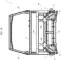
- reference 1 indicates - in its entirety - the frame of an electric vehicle, comprising a main cell module 1A, a front anti-crash module 1B rigidly connected to a front portion of the main cell module 1A, and a rear frame module 1C rigidly connected to a rear portion of the main cell module 1A.
- Each of the modules 1A, 1B, 1C consists of a reticular structure formed by high-strength steel arms 2, welded together, each arm having a hollow structure with a quadrangular cross-section.
- the main cell module 1A includes two lower side longitudinal members 2A connected to each other by cross-members 2B. The lower ends of two front side uprights 2C and two central side uprights 2D are welded to the longitudinal members 2A.
- the frame 1 also includes a superstructure wherein the arms 2 define two side beams 2E connected to each other by cross-members 2F.
- additional side uprights 2G, 2H are provided, connected below to the rear frame module 1C and above to the side beams 2E.
- the front frame module 1B has an upper part including four longitudinal beams 2L projecting forwards, the front ends of which are connected by a front cross-member 2M.
- the lower part of the module 1B includes two additional longitudinal beams 2L, also protruding forwards and ending with flanges for coupling with a crossbar (not visible in the drawing), forming part of the structure of a front bumper 3.
- the longitudinal beams 2L are configured in such a way as to be able to absorb impact energy, through their controlled deformation, as will be described in more detail below.
- References 3 and 4 indicate the structure of the vehicle's front and rear bumpers intended to be connected to the front 1B and rear 1C frame modules.
- the front bumper if produced in composite material according to a previous proposal by the same Applicant, has characteristics of particular stiffness and non-linear elasticity such as to improve performance in the event of a frontal and off-axis crash.
- a floor structure F Connected to the two lower side longitudinal members 2A is a floor structure F, which will be described in more detail below, which performs both a structural function and container function for the battery pack of the vehicle.
- the vehicle comprises a front axle unit 4 and a rear axle unit 4, substantially identical to each other, each having a sub-frame 4T (see Figure 2 ) rigidly connected, respectively, to the front frame module 1B and to the rear frame module 1C.
- the axle unit The axle unit
- the axle unit 4 comprises, for each wheel, a wheel support 5, better visible in Figures 18 and 19 , which is rotatably supported around a steering axis 6 by an upper pivoting arm 7 and by a lower pivoting arm 8, having a triangular configuration, better visible in Figures 3A, 3B .
- a spring-shock absorber assembly 9 is interposed between the lower triangle 8 and the frame 4T.
- Mounted on the frame 4T is a respective electric motor unit M connected by means of a gearbox unit R connected by means of homokinetic joints 11 to two shafts 10 which are - in turn - connected by means of homokinetic joints 12 to the wheel hubs H rotatably supported by the wheel supports 5.
- the frame 4T also carries a steering actuation device 13 connected by means of articulated tie rods 14 to the two wheel supports 5.
- the two axles are substantially identical, but they may differ in the ratio of the gearbox unit, for example, in one axle the reduction ratio may be 1:9 while in the other axle 1:6.5.
- the two axle units may operate completely independently or be controlled by a centralized controller that manages the torque delivery in the two axles in order to improve the stability of the vehicle in the presence of rain or in dangerous curves.
- the pivoting arms 7 and 8 of the suspension of each wheel each have a main body 15 made up of high resistance steel tubes cut with laser technique and joined by electrowelding, with an upper main wall 16 and a lower main wall 17, triangular in shape, parallel to each other and spaced apart.
- Two horizontal bushings, 18 coaxial with each other, are welded on the inner side of the triangular body 15, for articulated connection of the pivoting triangle to the frame 4T of the axle unit.
- a bushing 19 with a vertical axis is welded to the outer tip of the triangular body 15, for articulated connection of the wheel support around the steering axis.
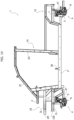
- Figure 18 of the attached drawings shows the detail of the connection of the wheel support 5 to the pivoting triangles 7, 8.
- the hinging device which allows the wheel support 5 to rotate around the steering axis 6 is arranged inside each bushing 19.
- a bracket 20 is also welded on the main body 15 of the lower triangle 8 for attaching the lower end of the spring-shock absorber assembly 9.
- the structure of the pivoting triangles 7, 8 allows a considerable simplification of the manufacturing operations and also a drastic reduction of the costs of the production equipment, given that it is not necessary to prepare elements obtained from molding or casting processes, since it is possible to make each component by simply bending and welding metal sheet elements.
- each wheel support 5 has a main body 5A consisting of tubular members in high-resistance steel cut with laser cutting and joined by electrowelding.
- a cylindrical ring 5B for the rotating support of the wheel hub H is welded to the main body 5A.
- An upper attachment 5C and a lower attachment 5D are also welded to the main body 5A, which are also made up of electro-welded tubular steel members, designed to carry the articulation pins, which are received in the hinge devices carried by the upper triangle 7 and the lower triangle 8.
- the vehicle configuration illustrated in Figure 1 is equipped with two front side doors and two rear side doors.
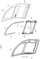
- Figure 4 shows an exploded view of the structure of a front side door, comprising a door frame 21 comprised between an inner door structure 22 and an outer door structure 23.
- the door frame 21 presents a reticular structure similar to that of the frame modules of the vehicle, formed by high-strength steel arms, welded together, each arm having a hollow structure with quadrangular cross-section.
- the arms constituting the door frame 21 include one front upright 21A, and one rear upright 21B, which are connected to each other by an upper cross-member 21C, by a lower cross-member 21D and by a diagonal arm 21E.
- the door also includes a window frame defined by guiding elements 24, 25, 26 defining an arched configuration having the opposite ends welded to the upper cross-member 21C of the door frame 21.
- the inner door structure 22 and the outer door structure 23 are in the form of metal sheet panels, which are coupled together keeping the door frame 21 interposed between them.
- Each panel 22, 23 includes a lower portion 22A, 23A, and an upper window frame 22B, 23B.
- the two frames 22B, 23B are coupled to each other and clamp the guide elements 24-26 together.
- the structure of the rear door is substantially similar to that of the front door shown in Figure 4 .
- Figure 5 shows the skeleton-frames 21 of the front door and the rear door.
- the frame-skeleton 21 of the rear door also includes uprights 21A, 21B connected together by an upper cross-member 21C and a lower cross-member 21D, which has an angled configuration as a consequence of the need to leave a free space occupied by the rear wheel fender.
- the frame-skeleton 21 of the rear door also has a diagonal arm 21E, and has an additional intermediate horizontal cross-member 21F, which connects the uprights 21A, 21B to each other in an intermediate position between the upper and lower cross-members 21C, 21D.
- the front upright 21A of each door frame-skeleton 21 carries brackets 21G for mounting the door hinging devices to the respective upright 2C or 2D of the vehicle frame.
- the doors also have a structure configured to allow - on the one hand - a drastic simplification of the manufacturing operations and a reduction in the cost of the production equipment and, however, to achieve - on the other hand - a high degree of safety and protection of passengers against the consequences of side impacts.
- FIG. 6 illustrates a configuration of the electric vehicle according to the invention in the form of a pick-up.
- the vehicle indicated - in its entirety - by the reference number 24, comprises a cabin 25 and a rear body 26 delimited by two side walls 27 and a rear wall 28.
- the aforesaid walls have panels of photovoltaic cells PV, the structure of which will be described below.
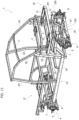
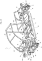
- the frame 1 of the pick-up vehicle 24 is visible in Figures 12-17 .
- a main cell module 1A is provided to which a front anti-crash frame module 1B and a rear frame module 1C are rigidly connected.
- the main cell module includes two lower side longitudinal members 2A to which the lower ends of two front uprights 2C and two central side uprights 2D are connected.
- the longitudinal members 2A are connected to each other by cross-members 2B.
- FIG. 12-17 shows the parts common to those of Figures 1 .
- Figure 17 also shows the floor F, which also acts as a container for the battery pack, which is associated with the frame 1 of the vehicle.
- this Figure illustrates a pick-up vehicle configuration wherein a superstructure consisting of a single roll-bar 29 is arranged behind the cabin 25.
- Figure 7 illustrates a variant wherein the superstructure arranged above the body 26 of the pick-up vehicle includes a front roll-bar 29 placed immediately behind the cab 25 and a rear roll-bar 30 arranged above the rear wall 28 of the body 26.
- Each of the two roll-bars 29, 30 consists of two uprights connected at the top by a cross-member. The upper ends of the uprights of the two roll-bars 29, 30 are also connected to each other by two longitudinal beams 31.
- photovoltaic cell panels PV are arranged not only on the outer walls 27, 28 of the body 26, but also on the roof of the cabin 25.
- Figure 8 shows an additional variant wherein the space defined by the superstructure of the body 26 is delimited by an upper panel 32 of photovoltaic cells PV, by two side panels 33 and by a rear panel 34.
- the two side panels 33 and the rear panel 34 are movable between the lowered position illustrated in Figure 8 , wherein they define a closed space above the body 26, and the raised position illustrated in Figure 9 , wherein they are rotated upwards around their upper horizontal edges.
- Figures 10 , 11 illustrate a variant of Figures 8 , 9 wherein the side panels 33, when they are in their raised position illustrated in Figure 9 , are also able to slide underneath the upper panel 32 defining the roof of the space above the body.
- the rear panel 34 may have side wings 34A that can be folded under the main part of the panel, to allow the rear panel 34 to slide under the upper panel 32 as well.
- each of the side panels 33 and the rear panel 34 have an ordered distribution in rows and columns of photovoltaic cells PV separated by cell-free strips.
- Passive display elements 40 for example, colored or reflective, or active, such as LED light sources, can be arranged at the intersections between the cell-free strips, which can be used to display writings or logos on the panels 33, 34.
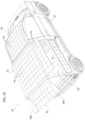
- Figures 20 , 21 show the preferred structure for the floor F, which also acts as a container for the battery pack.
- the floor-container F has a structure including a lower container body FA and an upper container body FB.
- Each of the bodies FA, FB is formed by two steel sheet panels 41, 42 parallel to each other and spaced apart, shaped by cutting and bending of the sheet, so as to present a main bottom wall surrounded by two side walls and two end walls. All the panels making up the body of the container are welded together along the peripheral edge.
- Each of the two panels constituting each container body FA, FB has an ordered distribution of impressions 43, which act both as spacer elements between the two panels and as structural elements, also suitable for reducing vibrations.
- the chamber comprised between each pair of panels 41, 42 is preferably filled with thermally insulating material.
- the front frame module 1B includes longitudinal beams 2L for absorbing impact energy, each consisting of an arm of the aforesaid reticular structure, projecting forwards, and having a hollow body with a quadrangular cross-section, in such a way as to have four longitudinal edges Z.
- Each of said longitudinal beams 2L has a series of openings H1-H5 for controlling the impact deformation, formed on each of said longitudinal edges Z in spaced apart positions, said openings H1-H5 presenting a decreasing amplitude from the front end of the longitudinal beam 2L towards the rear end, so as to induce a progressive deformation of the beam following a front impact, starting from the front end towards the rear end.
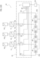
- Figures 22A-22D illustrate four different operating conditions of an embodiment of a connection circuit between the photovoltaic cells with which the vehicle is provided, and the battery pack and which allows use of the energy generated by the photovoltaic cells for recharging the battery pack.
- the battery pack for powering the electric drive motors of the vehicle comprises a plurality of battery modules Bi, four modules B1, B2, B3, B4 are shown in the example illustrated for the sake of simplicity.
- the four battery modules B1-B4 are connected in series with each other, so that the voltage across the battery pack, for example, 48V, 120V, 240V, 360V, 420V is the sum of the voltages at the heads of the individual battery modules, for example 24V, 36V, 48V, 60V.
- Each group or panel of photovoltaic cells PV1, PV2, ..., PVi is connected to the switching circuit 45 by means of a DC/DC converter C1, C2, ..., Ci, which carries the current from the supply voltage of the respective photovoltaic panel, for example, 9V or 24V, to the supply voltage of the single battery module, for example, 24V, 36V, 48V, 60V.
- a DC/DC converter C1, C2, ..., Ci which carries the current from the supply voltage of the respective photovoltaic panel, for example, 9V or 24V, to the supply voltage of the single battery module, for example, 24V, 36V, 48V, 60V.
- a Battery Management System 46 is also associated with the vehicle battery pack, designed to check the state of charge of the individual battery modules B1, B2, B3, B4, and an electronic control and processing unit E configured and programmed to control the switching circuit 45 according to the state of charge of the individual battery modules, in such a way as to dynamically vary the battery module that is being recharged in order to actively balance the state of charge of the various battery modules.
- each DC/DC converter C1, C2,..., Ci has a first pole PA and a second pole PB at its output.
- the switching circuit 45 comprises a plurality of switches S1, S2, ..., Si, each designed to connect one of the two poles of a respective battery module with all the first output poles PA of the DC/DC converters or with all the second output poles PB of the DC/DC converters.
- the battery pack has an end pole 47A, which can be connected or disconnected to all the first output poles PA of the DC/DC converters by means of a switch SA, and a second end pole 47B, which can be connected or disconnected to all the second output poles PB of the DC/DC converters via a switch SB.
- FIG. 22A illustrates a combination of the operating states of the different switches, so that only the battery module B1 is powered, with current generated by the photovoltaic panel PV1.
- Figure 22B shows the condition wherein only the battery module B2 is recharged, with current coming from the photovoltaic panel PV2.
- Figure 22C shows the operating condition wherein only the battery module B3 is recharged, with current generated from the photovoltaic panel PVi.
- Figure 22D shows the operating condition wherein the fourth battery module B4 is the only one to be recharged, by means of current generated from the photovoltaic panel PVi.
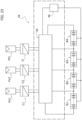
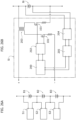
- FIG 23 is a generalization of the diagram of Figures 22A-22D where the switching circuit 45 is schematized as a block. In the case of the diagram of Figure 23 , it is the Battery Management System 46 that directly controls the switching circuit 45 as a function of the state of charge of the different battery modules.
- the recharging of the battery pack may be carried out more efficiently and by making use of simpler and less expensive components, since each DC/DC converter must supply current at a voltage that is the voltage across a single battery module.
- the system according to the invention allows the recharging of the battery pack to be managed dynamically, keeping the state of charge of the various battery modules actively balanced as much as possible.
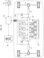
- Figure 24 is an additional diagram of the connection circuit between the battery modules of the battery pack, the photovoltaic panels with which the vehicle is equipped, the front and rear drive electric motors of the vehicle, and the connector for charging the battery pack by means of an external power supply network.
- the reference BP indicates the entire battery pack comprising the battery modules B1, B2, B3, B4, connected to each other in series, which can be recharged by the photovoltaic cell panels PV1, PV2, ..., PVi by means of the DC/DC C1, C2,..., Ci and the switching circuit 45 whose operating condition is controlled by the Battery Management System 46.
- an inverter 51 is associated with each drive electric motor M.
- the Battery Management System is configured and programmed to inhibit the operation of the regenerative braking energy system when a state of charge of the battery modules of the battery pack is detected beyond a predefined limit.
- the generation of generative energy is switched off during deceleration, during a descent or when braking the vehicle.
- braking is achieved in a conventional way, by actuating disc brakes associated with the wheels of the vehicle.
- Figure 25 represents an additional and preferred embodiment, which is capable of optimizing the active balancing of the battery pack avoiding short-circuit situations.
- the battery modules with the lowest state of charge reach full capacitance before the more charged battery modules.
- the power of the photovoltaic panels may be transferred to the battery modules with a charge transfer efficiency greater than 90%.
- each circuit communicates the state of charge of the respective battery module, so that no battery module becomes overcharged compared to the others.
- active balancing consists of injecting charge (current) into the battery module (for example, a single battery cell or a group of battery cells) with the lowest state of charge. This allows obtaining a similar state of charge in all battery modules and, therefore, pursuing an energy balance in all the elements. In doing this, the galvanic isolation in each series guarantees full safety on the side of the panel PV in all operating conditions.
- Figures 27-29 illustrate three different operating conditions of an electric vehicle which is not part of the invention, comprising a self-adaptive circuit for selecting the voltage value at which the battery pack operates for simplicity represented by the battery modules B1, B2, B3, B4.
- the circuit comprises a plurality of connection switches S1, S2, S3, S4, S5, S6, which can each be switched between a first position and a second position by means of a respective solenoid controlled by the electronic control and processing unit E.
- Reference 54 indicates any source of energy for recharging the battery module, which can be constituted by the panels of photovoltaic cells, or by an external power supply network, or by the regenerative system that recovers the braking energy.
- the connection circuit also comprises a main switch 55 and an additional relay-switch 56 for connection to the inverter associated with the electric drive motor.
- the electronic unit E checks the status of the different switches S1-S6 to produce different connection conditions of the battery modules in the different operating steps of the vehicle.
- Figure 27 shows a first operating condition wherein the battery modules are connected in series with each other. This configuration is optimal when charging the battery modules as it allows the power supply current to be kept low.
- the battery modules are connected in series with each other during the recharging phase, in order to increase the recharge voltage (for example, 200V or 300V or 400V and more) and, therefore, keep the power supply current low in order to be able to increase the charging speed by reducing the stress of the battery cells.
- the system of the switches prepares the entire pack to operate in the manner wherein the modules are connected in series.
- FIG 28 shows the operating condition wherein the battery modules are connected in parallel with each other.
- This condition is an optimal condition in the step of use with the vehicle in motion wherein the battery modules power the electric drive motors of the vehicle (the relay switch 56, which was open in the condition of Figure 27 , is instead closed in the condition of Figure 28 , while the main switch 55, which was closed in the condition of Figure 27 is open in the condition of Figure 28 ; the additional switch 57, which was closed in the condition of Figure 27 remains closed in the condition of Figure 28 ).
- Management of the switches enables hybrid solutions wherein modules are connected in series in pairs, and the two resulting pairs are connected in parallel.
- Figure 29 shows a third switching configuration, wherein the battery modules are isolated from each other. This condition is achieved when the electric vehicle is stationary with the electric motors inactive. In this condition, all three switches 56, 55 and 57 are open.
- Figure 30 shows the stratified structure of any panel with which the vehicle according to the invention is equipped, carrying an array of photovoltaic cells.
- the cells are incorporated in a layered laminar structure, including an outermost layer 100 facing the sun comprising one or more layers of PET with a UV or ECTFE coating, two layers of a thermoplastic polyolefin material 101, above and below the cells PV, to encapsulate the cells, and a rear rigid layer of structural glass fiber, which replaces the UV-coated PET panel, in place of which flexible panels are usually built.
- the composite panel thus composed is built in a vacuum chamber at a controlled temperature suitable for melting the intermediate layers of polyolefin material 101, avoiding the formation of air bubbles between the layers.
- the laminar sandwich composite is formed by keeping the transparent surface in contact with a smooth surface, while on the side consisting of the glass fiber it presses a membrane with such pressure as to ensure adhesion of the layers.
- the vehicle according to the invention has a series of innovative contents aimed - on the one hand - at drastically reducing the complexity of the vehicle structure and the costs of production equipment, at improving the degree of safety of the vehicle and the protection of the driver and passengers against the consequences of collisions, as well as - at the same time - identifying new vehicle configurations, such as the configuration of pick-up vehicles and vans, wherein arrangements of photovoltaic cell panels are made in combination with configurations that increase the functionality and ease of use of the vehicle.
- improved forms of circuits have been developed for active recharging of the battery modules by means of photovoltaic panels.
- Other circuit forms allow a dynamic reconfiguration of the battery pack voltage and which - at the same time - increase both the efficiency of the recharging process and the safety level when the vehicle is stationary.
Landscapes
- Engineering & Computer Science (AREA)
- Mechanical Engineering (AREA)
- Transportation (AREA)
- Chemical & Material Sciences (AREA)
- Combustion & Propulsion (AREA)
- Power Engineering (AREA)
- Sustainable Energy (AREA)
- Sustainable Development (AREA)
- Life Sciences & Earth Sciences (AREA)
- Chemical Kinetics & Catalysis (AREA)
- Electrochemistry (AREA)
- General Chemical & Material Sciences (AREA)
- Architecture (AREA)
- Structural Engineering (AREA)
- Aviation & Aerospace Engineering (AREA)
- Microelectronics & Electronic Packaging (AREA)
- Manufacturing & Machinery (AREA)
- Body Structure For Vehicles (AREA)
- Vehicle Interior And Exterior Ornaments, Soundproofing, And Insulation (AREA)
Description
- The present invention relates to electric vehicles.
- A preferred application of the invention relates to electric vehicles for transporting people of the van or pick-up type. However, the disclosures at the basis of the present invention are of general application.
- The invention relates, in particular, to an electric vehicle of the type comprising:
- a frame, including a main cell module, a front anti-crash module rigidly connected to a front portion of the main cell module, and a rear frame module rigidly connected to a rear portion of the main cell module,
- wherein each of said frame modules consists of a reticular structure formed by high-strength steel arms, welded together, each arm having a hollow structure with a quadrangular cross-section,
- a front axle unit and a rear axle unit, each comprising:
- an axle frame rigidly connected to a respective front or rear frame module,
- an upper pivoting arm and a lower pivoting arm for each wheel of the axle unit, mounted hinged to the frame of the axle unit and carrying a respective wheel support in a rotatable way around a steering axis,
- a wheel hub rotatably supported by each wheel support,
- an electric motor unit carried by the axle frame and connected by means of transmission members to the wheel hubs of the two wheel supports, and
- a device for activating the steering of the wheels, carried by the frame of the axle unit,
- The Applicant is the owner of various patents and patent applications (see, for example,
WO2015/155697 A1 ,WO2015/145285 ,WO2016/055873 A1 ,WO2016/055874 A1 ,WO2018/065946 A1 ) relating to an electric vehicle of the type indicated above. The Applicant's continuous research and experience in relation to the development of this vehicle have led to a breakthrough in the field of small electric vehicles, usable as city cars, or as small commercial vehicles, minivans or mini pickups. - A first objective that the Applicant intends to achieve is that of a drastic reduction of the investment costs necessary to implement a series production of vehicles of this type. The conventional technique used in the construction of motor-vehicle bodies and their sub-assemblies is very complex and requires the provision of expensive production equipment. It follows that for each new model to be introduced into production it is necessary to envisage a significant economic investment, which often constitutes a limit for vehicle manufacturers to the possibility of reacting promptly to market demands.
- The structure of the frame of the electric vehicle, which was developed by the Applicant, and which was the subject of the patent documents identified above, allows drastic reduction of the costs of the production equipment of the motor-vehicle. This was achieved in the first place by replacing the traditional body, consisting of pressed metal sheet elements welded together, with a reticular frame having the configuration described above. Production in series of a frame of this type does not require the preparation of complex, bulky and expensive production structures.
- Furthermore, configuration of the vehicle frame developed by the Applicant also has the advantage of being able to be configured not only in such a way as to easily pass all the crash tests required by regulations, but also to give the entire structure a degree of safety and of very high impact energy absorption capacity.
- In continuing his research and development activity, the Applicant has again identified the possibility of further improvements in terms of simplifying the construction of the vehicle and in terms of the resistance characteristics and the capacity of absorbing impact energy of the vehicle structure.
- More generally, an additional objective that the Applicant intends to achieve is that of further simplifying the construction of the vehicle, maintaining and preferably improving the level of safety that the vehicle achieves in terms of protection of the driver and passengers in the event of a crash.
- An additional objective of the Applicant is that of producing a new electric vehicle configuration, usable particularly as a minivan or mini pick-up. In particular, the Applicant intends to provide a new vehicle configuration of this type, which can exploit in a particularly efficient way an arrangement of photovoltaic cells arranged on the outer surfaces of the vehicle, and usable for recharging the battery pack of the electric vehicle.
- Yet another problem that the Applicant intends to solve is that of drastically improving the efficiency of the recharging process of the battery pack of the electric vehicle, both in the recharging phase by an outer power supply network, and in the recharging step while the vehicle is running, by means of a braking energy recovery system, and in a recharging step by photovoltaic cells with which the electric vehicle is equipped.
- In view of the above, a first object of the invention is to further improve the vehicle previously proposed by the same Applicant, making its construction even simpler and cheaper.
- An additional object of the invention is to produce a vehicle with a high capacity for absorbing impact energy and with a high degree of protection for the driver and passengers in the event of collisions.
- An additional specific object of the present invention is to drastically simplify not only the construction of the vehicle frame, but also that of additional components, such as the suspension elements and the doors, consequently reducing the investment costs necessary to prepare the corresponding production.
- An additional object of the invention is to propose a new electric vehicle configuration of the type indicated above, usable in particular for vehicles of the van or pick-up class, wherein it is possible to provide an extensive and - at the same time - efficient use of arrays of photovoltaic cells that can be used to recharge the vehicle battery pack.
- An additional object of the invention is to propose a battery pack recharging system with the aid of photovoltaic panels that allows active balancing of the battery pack.
- Finally, yet another object, no less important than the previous ones, that the present invention aims to achieve is to drastically improve the efficiency and duration of the battery pack by means of its dynamic reconfiguration during vehicle use.
- In view of achieving one or more of the aforesaid objects, the present invention relates to an electric vehicle having all the characteristics disclosed at the beginning of this description and also characterized in that:
- said upper pivoting arm and said lower pivoting arm associated with each wheel each have a main body consisting of elements obtained from high-resistance steel tubes cut by laser cutting and welded together, with an upper main wall and a lower main wall, both triangular in shape, parallel and spaced apart, defining a base side of the triangular configuration at the ends of which two horizontal bushings are welded coaxial with each other, for the articulated connection to the frame of the respective axle unit, and with an outer tip of the triangle configuration to which a vertical axis bushing is welded for the articulated connection of the wheel support around the steering axis,
also the wheel support, connected to said upper pivoting arm and to said lower pivoting arm, has a main body consisting of tubular members in high resistance steel welded together, - a cylindrical ring for the rotatable support of the wheel hub is welded to said main body of the wheel support, and
- an upper attachment and a lower attachment are welded to said main body of the wheel support, also made of high-strength steel tubes and welded together, intended to receive articulated supports for the rotatable connection to the upper and lower pivoting arms around said steering axis.
- Thanks to the aforesaid characteristics, the structure of the suspension elements, consisting of the upper arm and the lower arm carrying each wheel support, and the wheel support, is also drastically simplified.
- Another characteristic of the invention lies in the fact that the aforesaid floor also acting as a container for the battery pack (BP) has a structure including a lower container body and an upper container body having peripheral edges rigidly connected to each other,
- wherein each of said lower and upper container bodies is formed by two metal sheet panels parallel to each other and spaced apart, shaped by cutting and bending, so as to present a main bottom wall surrounded by two side walls and two end walls,
- wherein one or both of the two metal sheet panels of each container body has an ordered distribution of imprints, which act both as spacer elements between the two panels, and as stiffening elements, and
- wherein the space between the two panels of each of said lower and upper container bodies acts as an insulating chamber, and may be filled with insulating material also having the function of reducing vibrations.
- The structure of the floor of the vehicle according to the invention is, therefore, such as not to require any molding operation and consequently does not require the preparation of corresponding equipment. Each of the sheet metal panels is obtained starting from a semi-finished product obtained by a cutting operation and then brought into the final configuration by folding operations. The impressions acting as spacer elements are preliminarily made in the corresponding panel with equipment that can be greatly simplified.
- Still according to an additional characteristic of the invention, the aforesaid front frame module includes longitudinal beams for absorbing impact energy, each consisting of an arm of the reticular structure, projecting forwards, having a hollow body with a quadrangular cross-section, in such a way as to have four longitudinal edges, and in that each of said longitudinal beams has a series of openings for controlling the impact deformation, formed on some or all of the aforesaid longitudinal edges in spaced apart positions, said openings presenting a decreasing amplitude from the front end of the beam towards the rear end, so as to induce a progressive deformation of the beam following a front impact, starting from the front end towards the rear end.
- According to an additional characteristic, the vehicle comprises at least two front doors, articulated to the cell module of the vehicle frame, each comprising a door frame having opposite faces covered by an inner door structure and an outer door structure, wherein the door frame includes a reticular structure similar to that of the aforesaid frame modules, formed by high-strength steel arms, welded together, each arm having a hollow structure with a quadrangular cross-section, wherein said arms constituting the door frame include at least one front upright, and one rear upright, which are rigidly connected to each other by an upper cross-member, a lower cross-member and a diagonal arm, wherein each door includes a window frame defined by auxiliary elements substantially forming an arch, having the ends rigidly connected to said upper cross-member of the door frame, and wherein the inner door structure and the outer door structure are constituted by steel sheet panels rigidly connected on opposite sides to said door frame, and including respective window frames in a single piece, which clamp together the aforesaid arch connected to the upper cross-member of the door frame .
- Thanks to the characteristics indicated above, the construction of the vehicle doors is radically simplified, while - at the same time - the diagonal arm forming part of the door frame constitutes an important protection for the safety of the driver and passengers in the event of side impacts.
- According to an additional aspect, the invention relates to an electric vehicle of the type described above, characterized in that:
- the vehicle frame has a configuration for a pick-up or van including a superstructure formed by a front roll-bar, a rear roll-bar and two upper side longitudinal members and in that:
- said superstructure supports:
- an upper panel of photovoltaic cells serving as a roof,
- two side panels of photovoltaic cells covering the two sides of said superstructure, and
- a rear panel of photovoltaic cells covering the rear frame of said superstructure, and
- said superstructure supports:
- In one embodiment, in their raised position the side panels and the rear panel are arranged to slide under the roof panel.
- Furthermore, in one example, the vehicle carries auxiliary panels of photovoltaic cells, which are arranged stationary on the sides and rear of the vehicle, below the aforesaid superstructure.
- According to another characteristic, in each panel of photovoltaic cells, the cells are incorporated in a layered laminar structure, including an outermost layer comprising one or more layers of PET with a UV or ECTFE coating, two layers of a thermoplastic polyolefin material, above and below the cells, to encapsulate the cells, with a rear layer of structural glass fiber, which replaces the solutions based on a rear layer of PET with UV coating.
- According to another preferred characteristic, each panel of photovoltaic cells has an ordered distribution in rows and columns of photovoltaic cells, separated by cell-free strips or zones, and in that in at least some of the intersections between the said cell-free strips or zones reflecting devices or LED light sources are arranged, configured to display - as an assembly - passive colored or reflective or active writings and/or logos through the LED sources.
- According to another aspect, the invention comprises one or more outer surfaces covered by one or more panels of photovoltaic cells connected to a recharging circuit of the battery pack, which powers the electric drive motors of the vehicle, wherein:
- said battery pack comprises a plurality of battery modules or partitions connected in series with each other, so that the voltage across the battery pack (for example 48V or 120V or 360V, or 420V) is the sum of the voltages across the individual battery modules or partitions (for example, 24V or 30V or 60V, or more specifically at a voltage submultiple of the voltage of the entire battery pack),
- said recharging circuit comprises a switching circuit configured to connect one or more groups or panels of said photovoltaic cells, selectively to any of said battery modules or partitions in such a way that each battery partition module is supplied with current at the supply voltage of the single battery module-partition, (for example 24V, or more specifically, at a voltage submultiple of the voltage of the entire battery pack),
- each photovoltaic cell or each group or panel of photovoltaic cells is connected to said switching circuit by means of a DC/DC converter, which carries the current from the supply voltage of the cell (for example, between 3 V and 30 V) to the supply voltage of the single battery module (e.g. 24 V or more specifically at a voltage submultiple of the voltage of the entire battery pack), which is a submultiple of the voltage of the entire battery pack.
- Thanks to this characteristic, the circuit components are simplified and cheaper, the efficiency of the charging process is improved, and the invention also allows application of active balancing of the pack partitions using photovoltaic cells.
- In the preferred embodiment, a Battery Management System is associated with said battery pack, designed to control the state of charge of the individual battery modules, and an electronic control and processing unit, which is configured and programmed to control the aforesaid switching circuit depending on the state of charge of the individual battery modules, in such a way as to actively balance the battery module that is being recharged, in order to maintain a substantially uniform state of charge of the various battery modules.
- Thanks to the aforesaid characteristic, the invention therefore allows an "active" balancing of the battery pack charge through photovoltaic cells.
- In one example, each DC/DC converter has a first pole and a second pole at its output, and said switching circuit comprises a plurality of switches each designed to connect one of the two poles of a respective battery module with all the first output poles of the DC/DC converters or with all the second output poles of the DC/DC converters.
- In a variant, which eliminates the risk that the aforesaid switches may be in a combination of operating states that gives rise to a short circuit, each DC/DC converter has a first pole and a second pole at its output, the switching circuit comprises a plurality of galvanic isolation circuits, each having two input heads and two output heads, the two output heads of each galvanic isolation circuit are connected to the two poles of a respective battery module, and the two input heads of each galvanic isolation circuit are connected one to all the first output poles of said DC/ DC converters and the other to all the second output poles of said DC/DC converters.
- Also in the case of this second example, the battery pack is associated with a Battery Management System designed to control the state of charge of the individual battery modules, and an electronic control and processing unit, which is configured and programmed to control the aforesaid galvanic isolation circuits according to the state of charge of the individual battery modules, in such a way as to dynamically vary the battery modules that are being recharged, in order to balance the state of charge of the different battery modules.
- According to another aspect, a Battery Management System is associated with the battery pack, configured to control the state of charge of the battery pack, and communicates with the inverter in such a way as to regulate the level of regenerative braking and, therefore, the flow of energy towards the battery, and possibly disable the regenerative braking when a battery charge state above a predefined level is detected.
- According to another aspect which is not part of the invention, the electric vehicle comprises a circuit for recharging the vehicle battery pack by an external power supply network or, while the vehicle is running, by a braking energy recovery system. To improve the efficiency of the charging process, the vehicle is characterized in that:
- said battery pack comprises a plurality of battery modules,
- the vehicle comprises a connection circuit of said battery modules including a plurality of connection switches, each switchable between a first position and a second position, and
- during a battery module recharge phase, said connection switches are in a first switching configuration, wherein the battery modules are connected in series with each other,
- when the electric vehicle is in motion, said connection switches are in a second switching configuration, wherein the battery modules are connected in parallel with each other or partially in series and partially in parallel, and
- when the electric vehicle is stationary with the electric motors inactive, said connection switches are in a third switching configuration, wherein the battery modules are isolated from each other.
- Thanks to the aforesaid characteristics, the battery modules are connected in series with each other during the recharging phase, in order to increase the recharge voltage (for example, 200V or 300V or 400V and more) and, therefore, to keep the power supply current low in order to be able to increase the charging speed by reducing the stress of the battery cells. In the previous instant wherein recharging begins, the system of the switches prepares the entire pack to operate in the manner wherein the modules are connected in series.
- In the configuration wherein the modules are disconnected from each other, the maximum voltage of the entire circuit is that of the single module, this configuration is, therefore, characterized by the safety wherein an operator can intervene on the pack avoiding the risks due to high voltage. Similarly, when the vehicle is stationary and not charging, the circuit of the switches autonomously disconnects the modules from each other. While running, the system of the switches can reconnect all the modules in series or reconfigure them in such a way as to supply a multiple voltage of the submodules, for example, in a configuration whereby the two-by-two modules operate in parallel and the two pairs in series.
- Further characteristics and advantages of the invention will become apparent from the description that follows with reference to the attached drawings, provided purely by way of non-limiting example, wherein:
-
Figure 1 is an exploded perspective view of the main components of the structure of the vehicle according to the invention, in an embodiment example, -
Figure 2 is a perspective view of an axle unit of the vehicle ofFigure 1 , -
Figures 3A, 3B are perspective views of an upper pivoting arm and a lower pivoting arm of the suspension of a wheel of the vehicle ofFigure 1 , -
Figure 4 is an exploded perspective view of the structure of a door of the vehicle ofFigure 1 , -
Figure 5 illustrates a perspective view of the frame of a front door and a rear door of the vehicle ofFigure 1 , -
Figure 6 is another embodiment example of the vehicle according to the invention, in a pick-up configuration, -
Figure 7 is a perspective view of a vehicle of the type ofFigure 6 with a superstructure including two roll-bars, -
Figure 8 is a perspective view of another configuration of the pick-up vehicle ofFigures 6 ,7 , -
Figure 9 illustrates the vehicle ofFigure 8 with a plurality of panels carrying photovoltaic cells shown in their raised position, -
Figure 10 is a perspective view of an additional variant of the pick-up vehicle, -
Figure 11 is an additional perspective view of the variant ofFigure 10 , -
Figures 12-17 are perspective views and orthogonal views illustrating the frame of the vehicle in the pick-up and van configurations, -
Figure 18 is a perspective view of the detail of the elements of the suspension system of each wheel, -
Figure 19 is a perspective view on an enlarged scale of a wheel support, -
Figure 20 is a cross-sectioned perspective view of the floor of the vehicle according to the invention, -
Figure 21 is an exploded perspective view of the floor ofFigure 20 , -
Figures 22A-22D indicate four different operating conditions of a circuit for connecting the photovoltaic cells of which the vehicle is equipped with the various modules of a vehicle battery pack, -
Figure 23 is a variant ofFigures 22A-22D , -
Figure 24 illustrates the overall scheme of energy management from the battery pack to the powertrain, to the on-board photovoltaic panels and to the network, -
Figure 25 illustrates a variant of the connection circuit between the photovoltaic cells and the battery modules suitable for the active balancing of the pack, -
Figures 26A, 26B illustrate additional diagrams of the variant ofFigure 25 , -
Figures 27-29 illustrate three different operating conditions of a connection circuit of the different battery modules suitable for dynamic configuration of the battery pack, with the vehicle being recharged from the mains, the vehicle stationary and the vehicle in motion, -
Figure 30 illustrates the stratified structure of each panel bearing the photovoltaic cells with which the vehicle according to the invention is provided, wherein the substrate is constituted by a thin structural element in glass fiber. - In
Figure 1 ,reference 1 indicates - in its entirety - the frame of an electric vehicle, comprising amain cell module 1A, a frontanti-crash module 1B rigidly connected to a front portion of themain cell module 1A, and arear frame module 1C rigidly connected to a rear portion of themain cell module 1A. - Each of the
modules strength steel arms 2, welded together, each arm having a hollow structure with a quadrangular cross-section. With reference to the specific example illustrated, themain cell module 1A includes two lower sidelongitudinal members 2A connected to each other by cross-members 2B. The lower ends of twofront side uprights 2C and twocentral side uprights 2D are welded to thelongitudinal members 2A. In the example ofFigure 1 , theframe 1 also includes a superstructure wherein thearms 2 define twoside beams 2E connected to each other by cross-members 2F. At the rear, in the illustrated example,additional side uprights rear frame module 1C and above to the side beams 2E. - The
front frame module 1B has an upper part including fourlongitudinal beams 2L projecting forwards, the front ends of which are connected by afront cross-member 2M. The lower part of themodule 1B includes two additionallongitudinal beams 2L, also protruding forwards and ending with flanges for coupling with a crossbar (not visible in the drawing), forming part of the structure of afront bumper 3. Thelongitudinal beams 2L are configured in such a way as to be able to absorb impact energy, through their controlled deformation, as will be described in more detail below. -
References - Connected to the two lower side
longitudinal members 2A is a floor structure F, which will be described in more detail below, which performs both a structural function and container function for the battery pack of the vehicle. - Still with reference to
Figure 1 , the vehicle comprises afront axle unit 4 and arear axle unit 4, substantially identical to each other, each having asub-frame 4T (seeFigure 2 ) rigidly connected, respectively, to thefront frame module 1B and to therear frame module 1C. - With reference to
Figure 2 , theaxle unit 4 comprises, for each wheel, awheel support 5, better visible inFigures 18 and19 , which is rotatably supported around asteering axis 6 by anupper pivoting arm 7 and by alower pivoting arm 8, having a triangular configuration, better visible inFigures 3A, 3B . A spring-shock absorber assembly 9 is interposed between thelower triangle 8 and theframe 4T. Mounted on theframe 4T is a respective electric motor unit M connected by means of a gearbox unit R connected by means ofhomokinetic joints 11 to twoshafts 10 which are - in turn - connected by means ofhomokinetic joints 12 to the wheel hubs H rotatably supported by the wheel supports 5. Theframe 4T also carries asteering actuation device 13 connected by means of articulatedtie rods 14 to the two wheel supports 5. In the preferred fourwheel drive configuration, the two axles are substantially identical, but they may differ in the ratio of the gearbox unit, for example, in one axle the reduction ratio may be 1:9 while in the other axle 1:6.5. The two axle units may operate completely independently or be controlled by a centralized controller that manages the torque delivery in the two axles in order to improve the stability of the vehicle in the presence of rain or in dangerous curves. - With reference to
Figures 3A, 3B , the pivotingarms main body 15 made up of high resistance steel tubes cut with laser technique and joined by electrowelding, with an uppermain wall 16 and a lowermain wall 17, triangular in shape, parallel to each other and spaced apart. Two horizontal bushings, 18 coaxial with each other, are welded on the inner side of thetriangular body 15, for articulated connection of the pivoting triangle to theframe 4T of the axle unit. On the other hand, abushing 19 with a vertical axis is welded to the outer tip of thetriangular body 15, for articulated connection of the wheel support around the steering axis. -
Figure 18 of the attached drawings shows the detail of the connection of thewheel support 5 to the pivotingtriangles wheel support 5 to rotate around the steeringaxis 6 is arranged inside eachbushing 19. - Again with reference to
Figure 3B , abracket 20 is also welded on themain body 15 of thelower triangle 8 for attaching the lower end of the spring-shock absorber assembly 9. - As is evident from the above description, the structure of the pivoting
triangles - With reference to
Figure 19 , the same concept has also been applied to the preferred embodiment for the wheel supports 5. Indeed, eachwheel support 5 has amain body 5A consisting of tubular members in high-resistance steel cut with laser cutting and joined by electrowelding. Acylindrical ring 5B for the rotating support of the wheel hub H is welded to themain body 5A. Anupper attachment 5C and alower attachment 5D are also welded to themain body 5A, which are also made up of electro-welded tubular steel members, designed to carry the articulation pins, which are received in the hinge devices carried by theupper triangle 7 and thelower triangle 8. - Again with reference to
Figures 1 and4 ,5 , the vehicle configuration illustrated inFigure 1 is equipped with two front side doors and two rear side doors. -
Figure 4 shows an exploded view of the structure of a front side door, comprising adoor frame 21 comprised between aninner door structure 22 and anouter door structure 23. Thedoor frame 21 presents a reticular structure similar to that of the frame modules of the vehicle, formed by high-strength steel arms, welded together, each arm having a hollow structure with quadrangular cross-section. In particular, the arms constituting thedoor frame 21 include onefront upright 21A, and onerear upright 21B, which are connected to each other by anupper cross-member 21C, by alower cross-member 21D and by adiagonal arm 21E. - Still with reference to
Figure 4 , the door also includes a window frame defined by guidingelements upper cross-member 21C of thedoor frame 21. Theinner door structure 22 and theouter door structure 23 are in the form of metal sheet panels, which are coupled together keeping thedoor frame 21 interposed between them. Eachpanel lower portion - The structure of the rear door is substantially similar to that of the front door shown in
Figure 4 .Figure 5 shows the skeleton-frames 21 of the front door and the rear door. The frame-skeleton 21 of the rear door also includesuprights upper cross-member 21C and alower cross-member 21D, which has an angled configuration as a consequence of the need to leave a free space occupied by the rear wheel fender. The frame-skeleton 21 of the rear door also has adiagonal arm 21E, and has an additional intermediatehorizontal cross-member 21F, which connects theuprights front upright 21A of each door frame-skeleton 21 carriesbrackets 21G for mounting the door hinging devices to therespective upright - As is evident from the above description, in the vehicle according to the invention the doors also have a structure configured to allow - on the one hand - a drastic simplification of the manufacturing operations and a reduction in the cost of the production equipment and, however, to achieve - on the other hand - a high degree of safety and protection of passengers against the consequences of side impacts.
-
Figure 6 illustrates a configuration of the electric vehicle according to the invention in the form of a pick-up. The vehicle, indicated - in its entirety - by thereference number 24, comprises acabin 25 and arear body 26 delimited by twoside walls 27 and arear wall 28. In the preferred embodiment illustrated here, the aforesaid walls have panels of photovoltaic cells PV, the structure of which will be described below. - The
frame 1 of the pick-upvehicle 24 is visible inFigures 12-17 . In this case as well, as in the case of the configuration illustrated inFigure 1 , amain cell module 1A is provided to which a frontanti-crash frame module 1B and arear frame module 1C are rigidly connected. In this case as well, the main cell module includes two lower sidelongitudinal members 2A to which the lower ends of twofront uprights 2C and twocentral side uprights 2D are connected. Thelongitudinal members 2A are connected to each other by cross-members 2B. - The structure of the front and
rear frame modules Figure 1 . Therefore, inFigures 12-17 , the parts common to those ofFigures 1 are indicated by the same reference numbers.Figure 17 also shows the floor F, which also acts as a container for the battery pack, which is associated with theframe 1 of the vehicle. - With reference again to
Figure 6 , this Figure illustrates a pick-up vehicle configuration wherein a superstructure consisting of a single roll-bar 29 is arranged behind thecabin 25. -
Figure 7 illustrates a variant wherein the superstructure arranged above thebody 26 of the pick-up vehicle includes a front roll-bar 29 placed immediately behind thecab 25 and a rear roll-bar 30 arranged above therear wall 28 of thebody 26. Each of the two roll-bars bars longitudinal beams 31. Both in the configuration ofFigure 6 and in the configuration ofFigure 7 , photovoltaic cell panels PV are arranged not only on theouter walls body 26, but also on the roof of thecabin 25. -
Figure 8 shows an additional variant wherein the space defined by the superstructure of thebody 26 is delimited by anupper panel 32 of photovoltaic cells PV, by twoside panels 33 and by arear panel 34. The twoside panels 33 and therear panel 34 are movable between the lowered position illustrated inFigure 8 , wherein they define a closed space above thebody 26, and the raised position illustrated inFigure 9 , wherein they are rotated upwards around their upper horizontal edges. -
Figures 10 ,11 illustrate a variant ofFigures 8 ,9 wherein theside panels 33, when they are in their raised position illustrated inFigure 9 , are also able to slide underneath theupper panel 32 defining the roof of the space above the body. In the case of the variant ofFigures 10 ,11 , therear panel 34 may haveside wings 34A that can be folded under the main part of the panel, to allow therear panel 34 to slide under theupper panel 32 as well. - Again with reference to
Figure 8 , each of theside panels 33 and therear panel 34 have an ordered distribution in rows and columns of photovoltaic cells PV separated by cell-free strips. Passive display elements 40, for example, colored or reflective, or active, such as LED light sources, can be arranged at the intersections between the cell-free strips, which can be used to display writings or logos on thepanels -
Figures 20 ,21 show the preferred structure for the floor F, which also acts as a container for the battery pack. According to this solution, the floor-container F has a structure including a lower container body FA and an upper container body FB. Each of the bodies FA, FB is formed by twosteel sheet panels impressions 43, which act both as spacer elements between the two panels and as structural elements, also suitable for reducing vibrations. The chamber comprised between each pair ofpanels - Still with reference to
Figures 18 ,12 ,13 ,14 ,15 ,17 , thefront frame module 1B includeslongitudinal beams 2L for absorbing impact energy, each consisting of an arm of the aforesaid reticular structure, projecting forwards, and having a hollow body with a quadrangular cross-section, in such a way as to have four longitudinal edges Z. Each of saidlongitudinal beams 2L has a series of openings H1-H5 for controlling the impact deformation, formed on each of said longitudinal edges Z in spaced apart positions, said openings H1-H5 presenting a decreasing amplitude from the front end of thelongitudinal beam 2L towards the rear end, so as to induce a progressive deformation of the beam following a front impact, starting from the front end towards the rear end. -
Figures 22A-22D illustrate four different operating conditions of an embodiment of a connection circuit between the photovoltaic cells with which the vehicle is provided, and the battery pack and which allows use of the energy generated by the photovoltaic cells for recharging the battery pack. - In the vehicle according to the invention, the battery pack for powering the electric drive motors of the vehicle comprises a plurality of battery modules Bi, four modules B1, B2, B3, B4 are shown in the example illustrated for the sake of simplicity.
- In the embodiment illustrated here, the four battery modules B1-B4 are connected in series with each other, so that the voltage across the battery pack, for example, 48V, 120V, 240V, 360V, 420V is the sum of the voltages at the heads of the individual battery modules, for example 24V, 36V, 48V, 60V.
- The recharging circuit of the battery modules B1-B4, indicated - in its entirety - with the reference 44, comprises a switching
circuit 45 configured to connect one or more groups (panels) of photovoltaic cells PV1, PV2, ..., PVi selectively to any one of the battery modules B1, B2, B3, B4, in such a way that each battery module is supplied with current at the supply voltage of the single battery module, i.e. for example with 24V, 36V, 48V, 60V current. Each group or panel of photovoltaic cells PV1, PV2, ..., PVi is connected to the switchingcircuit 45 by means of a DC/DC converter C1, C2, ..., Ci, which carries the current from the supply voltage of the respective photovoltaic panel, for example, 9V or 24V, to the supply voltage of the single battery module, for example, 24V, 36V, 48V, 60V. ABattery Management System 46 is also associated with the vehicle battery pack, designed to check the state of charge of the individual battery modules B1, B2, B3, B4, and an electronic control and processing unit E configured and programmed to control the switchingcircuit 45 according to the state of charge of the individual battery modules, in such a way as to dynamically vary the battery module that is being recharged in order to actively balance the state of charge of the various battery modules. - In the embodiment example of
Figures 22A-22D , each DC/DC converter C1, C2,..., Ci has a first pole PA and a second pole PB at its output. The switchingcircuit 45 comprises a plurality of switches S1, S2, ..., Si, each designed to connect one of the two poles of a respective battery module with all the first output poles PA of the DC/DC converters or with all the second output poles PB of the DC/DC converters. Furthermore, the battery pack has anend pole 47A, which can be connected or disconnected to all the first output poles PA of the DC/DC converters by means of a switch SA, and a second end pole 47B, which can be connected or disconnected to all the second output poles PB of the DC/DC converters via a switch SB. The status of the switches S1, S2, ..., Si and SA, SB is controlled by CAN BUS lines 48, or more generally by signal communication lines from the electronic control and processing unit E on the basis of the signals received from theBattery System Management 46 according to the state of charge of the various battery modules B1, B2, B3, B4.Figure 22A illustrates a combination of the operating states of the different switches, so that only the battery module B1 is powered, with current generated by the photovoltaic panel PV1.Figure 22B shows the condition wherein only the battery module B2 is recharged, with current coming from the photovoltaic panel PV2.Figure 22C shows the operating condition wherein only the battery module B3 is recharged, with current generated from the photovoltaic panel PVi.Figure 22D shows the operating condition wherein the fourth battery module B4 is the only one to be recharged, by means of current generated from the photovoltaic panel PVi. -
Figure 23 is a generalization of the diagram ofFigures 22A-22D where the switchingcircuit 45 is schematized as a block. In the case of the diagram ofFigure 23 , it is theBattery Management System 46 that directly controls the switchingcircuit 45 as a function of the state of charge of the different battery modules. - As is evident from the above description, on the one hand, the recharging of the battery pack may be carried out more efficiently and by making use of simpler and less expensive components, since each DC/DC converter must supply current at a voltage that is the voltage across a single battery module. At the same time, the system according to the invention allows the recharging of the battery pack to be managed dynamically, keeping the state of charge of the various battery modules actively balanced as much as possible.
-
Figure 24 is an additional diagram of the connection circuit between the battery modules of the battery pack, the photovoltaic panels with which the vehicle is equipped, the front and rear drive electric motors of the vehicle, and the connector for charging the battery pack by means of an external power supply network. InFigure 24 , the parts common to those ofFigures 22 ,23 are indicated by the same references. The reference BP indicates the entire battery pack comprising the battery modules B1, B2, B3, B4, connected to each other in series, which can be recharged by the photovoltaic cell panels PV1, PV2, ..., PVi by means of the DC/DC C1, C2,..., Ci and the switchingcircuit 45 whose operating condition is controlled by theBattery Management System 46. Thecircuit 45 is also connected to theconnector 49A for coupling with an externalpower supply network 48 by means of a bidirectional charging device 49. The device 49 allows both recharging of the battery pack by the externalpower supply network 48 and, in the reverse direction, the use of electrical energy stored in the battery pack BP for feeding into thenetwork 48 or supplying the electrical circuit of ahouse 50. - Again with reference to the diagram of
Figure 24 , aninverter 51 is associated with each drive electric motor M. - In the preferred embodiment, the Battery Management System is configured and programmed to inhibit the operation of the regenerative braking energy system when a state of charge of the battery modules of the battery pack is detected beyond a predefined limit. In this case, since there is no need to recharge the battery modules, the generation of generative energy is switched off during deceleration, during a descent or when braking the vehicle. In the latter case, braking is achieved in a conventional way, by actuating disc brakes associated with the wheels of the vehicle.
-
Figure 25 represents an additional and preferred embodiment, which is capable of optimizing the active balancing of the battery pack avoiding short-circuit situations. - In this case, the switching
circuit 45 comprises a plurality of galvanic isolation circuits S1, S2, S3, S4 each having two input heads I1, I2 and two output heads U1, U2, The two input heads I1, I2 are connected one to all the output poles PA of the DC/DC converters, and the other to all the output poles PB of the DC/DC converters. The two output heads U1, U2 of each galvanic isolation circuit are connected to the poles of a respective battery module B1, B2, B3, B4, As in the case of the embodiment described above, the electronic unit E controls the DC/DC converters and the S1-S4 circuits as a function of the signals received by theBattery Management System 46 relating to the state of charge of the different battery modules, in order to activate the galvanic isolation circuits. The switchingsystem 45 is able to selectively connect one or more of the photovoltaic cell panels with one or more of the battery modules so that the electronic unit E is able to dynamically manage the recharging of the different battery modules according to their state of charge, in order to keep the charge level of the different battery modules actively balanced. The diagram ofFigure 25 also illustrates theconnector 49A for recharging - by means of an external power supply network - a DC/DC converter 53 for recharging thebattery 54 at 12 V of the on-board electrical circuit of the vehicle and a DC/AC inverter 55 for the power supply of the electric drive motors M through the battery pack. -
Figure 26A schematically shows three galvanically isolated charging circuits S1, S2 and S3 connected to three battery modules B1, B2 and B3, andFigure 26B shows a configuration example of a single circuit Si including a galvanically isolated circuit. - In known systems wherein the battery pack is recharged without balancing, the battery modules with the lowest state of charge reach full capacitance before the more charged battery modules.
- With the active balancing achievable with the present invention, during the charge cycle, the battery can reach its full capacitance without unnecessary energy losses.
- With reference to
Figure 26B , the circuit Si comprises a galvanic isolation transformer 203 and anelectronic controller 200 configured and programmed to control two power transistors (FET) 201 through a driver 202, which may include an optical type isolator. Thecontroller 200 receives the signals from a voltage monitoring circuit 204 of the battery module Bi by means of a galvanic isolation circuit 205. - Each battery module Bi is charged by the circuit on the basis of the control carried out by the electronic control and processing unit E (
Figure 25 ) by means of thecontrollers 200 of each circuit. It is thus possible to monitor the voltage of the individual battery modules and to implement a charging strategy that maintains a perfect balance of the modules. - In this way, the power of the photovoltaic panels (PV) may be transferred to the battery modules with a charge transfer efficiency greater than 90%.
- During the entire charge cycle, each circuit communicates the state of charge of the respective battery module, so that no battery module becomes overcharged compared to the others.
- In particular, it is not necessary to discharge an overcharged battery module, which avoids wasting energy.
- Substantially, active balancing consists of injecting charge (current) into the battery module (for example, a single battery cell or a group of battery cells) with the lowest state of charge. This allows obtaining a similar state of charge in all battery modules and, therefore, pursuing an energy balance in all the elements. In doing this, the galvanic isolation in each series guarantees full safety on the side of the panel PV in all operating conditions.
-
Figures 27-29 illustrate three different operating conditions of an electric vehicle which is not part of the invention, comprising a self-adaptive circuit for selecting the voltage value at which the battery pack operates for simplicity represented by the battery modules B1, B2, B3, B4. In this embodiment, the circuit comprises a plurality of connection switches S1, S2, S3, S4, S5, S6, which can each be switched between a first position and a second position by means of a respective solenoid controlled by the electronic control and processingunit E. Reference 54 indicates any source of energy for recharging the battery module, which can be constituted by the panels of photovoltaic cells, or by an external power supply network, or by the regenerative system that recovers the braking energy. The connection circuit also comprises amain switch 55 and an additional relay-switch 56 for connection to the inverter associated with the electric drive motor. - The electronic unit E checks the status of the different switches S1-S6 to produce different connection conditions of the battery modules in the different operating steps of the vehicle.
Figure 27 shows a first operating condition wherein the battery modules are connected in series with each other. This configuration is optimal when charging the battery modules as it allows the power supply current to be kept low. - Thanks to the aforesaid characteristics, the battery modules are connected in series with each other during the recharging phase, in order to increase the recharge voltage (for example, 200V or 300V or 400V and more) and, therefore, keep the power supply current low in order to be able to increase the charging speed by reducing the stress of the battery cells. In the previous instant wherein recharging begins, the system of the switches prepares the entire pack to operate in the manner wherein the modules are connected in series.
-
Figure 28 shows the operating condition wherein the battery modules are connected in parallel with each other. This condition is an optimal condition in the step of use with the vehicle in motion wherein the battery modules power the electric drive motors of the vehicle (therelay switch 56, which was open in the condition ofFigure 27 , is instead closed in the condition ofFigure 28 , while themain switch 55, which was closed in the condition ofFigure 27 is open in the condition ofFigure 28 ; theadditional switch 57, which was closed in the condition ofFigure 27 remains closed in the condition ofFigure 28 ). Management of the switches enables hybrid solutions wherein modules are connected in series in pairs, and the two resulting pairs are connected in parallel. -
Figure 29 shows a third switching configuration, wherein the battery modules are isolated from each other. This condition is achieved when the electric vehicle is stationary with the electric motors inactive. In this condition, all threeswitches -
Figure 30 shows the stratified structure of any panel with which the vehicle according to the invention is equipped, carrying an array of photovoltaic cells. According to this solution, in each panel, the cells are incorporated in a layered laminar structure, including anoutermost layer 100 facing the sun comprising one or more layers of PET with a UV or ECTFE coating, two layers of athermoplastic polyolefin material 101, above and below the cells PV, to encapsulate the cells, and a rear rigid layer of structural glass fiber, which replaces the UV-coated PET panel, in place of which flexible panels are usually built. The composite panel thus composed is built in a vacuum chamber at a controlled temperature suitable for melting the intermediate layers ofpolyolefin material 101, avoiding the formation of air bubbles between the layers. The laminar sandwich composite is formed by keeping the transparent surface in contact with a smooth surface, while on the side consisting of the glass fiber it presses a membrane with such pressure as to ensure adhesion of the layers. - As is evident from the above description, the vehicle according to the invention has a series of innovative contents aimed - on the one hand - at drastically reducing the complexity of the vehicle structure and the costs of production equipment, at improving the degree of safety of the vehicle and the protection of the driver and passengers against the consequences of collisions, as well as - at the same time - identifying new vehicle configurations, such as the configuration of pick-up vehicles and vans, wherein arrangements of photovoltaic cell panels are made in combination with configurations that increase the functionality and ease of use of the vehicle. Furthermore, according to an additional aspect of the invention, improved forms of circuits have been developed for active recharging of the battery modules by means of photovoltaic panels. Other circuit forms allow a dynamic reconfiguration of the battery pack voltage and which - at the same time - increase both the efficiency of the recharging process and the safety level when the vehicle is stationary.
- Of course, without prejudice to the principle of the invention, the embodiments and construction details may widely vary with respect to those described and illustrated purely by way of example, without thereby departing from the scope of the invention, as defined in the attached claims.
Claims (15)
- An electric vehicle, in particular, an electric vehicle for transporting people, or a van or pick-up, comprising:- a frame (1), including a main cell module (1A), a front anti-crash module (1B) rigidly connected to a front portion of the main cell module (1A) and a rear frame module (1C) rigidly connected to a rear portion of the main cell module (1A),- wherein each of said frame modules (1A, 1B, 1C) consists of a reticular structure formed by high-strength steel arms (2), welded together, each arm (2) having a hollow structure with a quadrangular cross-section,- a front axle unit (4) and a rear axle unit (4), each comprising:- a frame (4T) rigidly connected to a respective front or rear frame module (1B, 1C),- an upper pivoting arm (7) and a lower pivoting arm (8) for each wheel of the axle unit (4), mounted hinged to the frame (4T) of the axle unit and carrying a respective wheel support (5) in a rotatable way around a steering axis (6),- a wheel hub (H) rotatably supported by each wheel support (5),- an electric motor unit (M) carried by the frame (4T) of the axle unit and connected by means of transmission members (R, 10, 11, 12) to the wheel hubs (H) of said wheel supports (5), and- a device (13) for activating the steering of the wheels, carried by the frame (4T) of the axle unit,said vehicle further comprising a floor (F) rigidly connected to two lower side longitudinal members (2A) of said main cell module (1A) and configured to act as a structural element of the vehicle frame and also as a container for the battery pack (BP), for the electrical power supply of said electric motor assemblies (M) associated with the two axle units,said vehicle being characterized in that:- said upper pivoting arm (7) and said lower pivoting arm (8) associated with each wheel each have a main body (15) consisting of elements obtained from high-resistance steel tubes cut by laser cutting and welded together, with an upper main wall (16) and a lower main wall (17), both triangular in shape, parallel to each other and spaced apart, defining a base side of the triangular configuration at the ends of which two horizontal bushings are welded (18), coaxial with each other, for the articulated connection to the frame (4T) of the respective axle unit, and with an outer tip of the triangle configuration to which a vertical axis bushing (19) is welded for the articulated connection of the wheel support (5) around the steering axis (6), and- also the wheel support (5), which is connected to said upper pivoting arm (7) and to said lower pivoting arm (8), has a main body (5A) consisting of tubular members of high-resistance steel welded together,- a cylindrical ring (5B) for the rotatable support of the wheel hub is welded to said main body (5A) of the wheel support (5), and- an upper attachment (5C) and a lower attachment (5D) are welded to said main body (5A) of the wheel support (5), said attachments being also made of high-strength steel tubes welded together, and being provided for receiving articulated supports for pivotal connection to the upper and lower pivoting arms (7, 8) around said steering axis (6).
- An electric vehicle according to claim 1, characterized in that the two axle units have independent motor units and including respective electric motors (M) identical to each other, but associated with gearbox assemblies (R) configured to achieve different transmission ratios, for example 1: 9 and 1: 6.5, respectively.
- An electric vehicle according to claim 1, characterized in that the aforesaid floor (F) also acting as a container for the battery pack (BP) has a structure including a lower container body (FA) and an upper container body (FB) having peripheral edges rigidly connected to each other,wherein each of said lower and upper container bodies (FA, FB) is formed by two metal sheet panels (41, 42) parallel to each other and spaced apart, shaped by cutting and bending, so as to present a main bottom wall surrounded by two side walls and two end walls,wherein one or both of the two metal sheet panels (41) of each container body (FA, FB) has an ordered distribution of imprints (43) which act as spacer elements between the two panels (41, 42), andwherein the space between the two panels (41, 42) of each of said lower and upper container bodies (FA, FB) is filled with insulating material.
- An electric vehicle according to any one of the preceding claims, characterized in that said front frame module (1B) includes longitudinal beams (2L) for absorbing impact energy, each consisting of an arm of the aforesaid reticular structure protruding forwards and having a hollow body with a quadrangular cross-section, so as to have four longitudinal edges (Z), and
in that each of said longitudinal beams (2L) has a series of openings (H1-H5) for controlling the impact deformation, formed on each of said longitudinal edges (Z) in spaced apart positions, said openings (H1-H5) presenting a decreasing amplitude from the front end of the longitudinal beam (2L) towards the rear end, so as to induce a progressive deformation of the beam following a front impact, starting from the front end towards the rear end. - An electric vehicle according to claim 1, characterized in that it comprises at least two front doors, articulated to the cell module (1A), each comprising a door frame-skeleton (21) having opposite faces covered by an inner door structure (22) and by an outer door structure (23),- wherein the door frame-skeleton (21) includes a reticular structure similar to that of the aforesaid frame modules (1A, 1B, 1C), formed by high-strength steel arms, welded together, each arm having a hollow structure with quadrangular cross-section,- wherein said arms constituting the door frame (21) include at least one front upright (21A), and one rear upright (21B), which are rigidly connected to each other by an upper cross-member (21C), by a lower cross member (21D) and a diagonal arm (21E),- wherein each door includes a window frame including guide elements (24, 25, 26) substantially forming an arch, which has its opposite ends rigidly connected to said upper cross member (21C) of the door frame (21), and- wherein the inner door structure (22) and the outer door structure (23) are constituted by steel sheet panels rigidly connected on opposite sides to said door frame (21) and including - in one piece - respective window frames (22B, 23B), which clamp together the aforesaid window frame (24-26) connected to the upper cross-member of the door frame (21).
- An electric vehicle according to claim 1, characterized in that:- said vehicle frame has a configuration for a pick-up vehicle or van including a superstructure comprising a front roll-bar (29), a rear roll-bar (30) and two upper side longitudinal members (31) and in that:wherein said side panels (33) and said rear panel (34) are movable between a lowered configuration, wherein said panels cover the respective sides of said superstructure, so as to define a closed space, and a raised configuration, wherein the panels are rotated upward around their upper horizontal edge.- said structure supports:- an upper panel of photovoltaic cells (32) serving as a roof,- two side panels (33) of photovoltaic (PV) cells covering the two sides of said superstructure, and- a rear panel (34) of photovoltaic (PV) cells covering the rear side of said superstructure, and
- An electric vehicle according to claim 6, characterized in that - in their raised position - the side panels (33) and/or the rear panel (34) are arranged to slide under the upper panel (32) acting as a roof.
- An electric vehicle according to claim 6, characterized in that the vehicle body is provided with auxiliary panels of photovoltaic cells arranged on the sides (27) and on the rear wall (28) of the vehicle, below the aforesaid superstructure.
- An electric vehicle according to claim 6, characterized in that in each panel of photovoltaic cells, the cells are incorporated in a layered laminar structure, including an outermost layer (100) comprising one or more layers of PET with a UV or ECTFE coating, two layers of a thermoplastic polyolefin material (101), above and below the cells, to encapsulate the cells (PV), and a thin rear layer (102) of structural glass fiber.
- An electric vehicle according to claim 6, characterized in that each panel of photovoltaic cells has an ordered distribution in rows and columns of photovoltaic (PV) cells separated by cell-free strips, and in that in at least some of the intersections between the aforesaid cell-free strips are arranged reflecting devices or LED light sources (40) configured to display as an assembly passive colored or reflective or active writings and logos through the LED sources.
- An electric vehicle according to claim 1, characterized in that it comprises one or more outer surfaces covered by one or more panels of photovoltaic cells connected to a recharging circuit of the battery pack (BP), which powers the electric drive motors (M) of the vehicle,in that said battery pack comprises a plurality of battery modules (B1, B2, B3, B4) connected in series with each other, so that the voltage across the battery pack is the sum of the voltage across the individual battery modules,in that said recharging circuit comprises a switching circuit (45) configured to connect one or more groups or panels of said photovoltaic (PV) cells, selectively to any of said battery modules (B1, B2, B3, B4), in such a way that each battery module is supplied with current at the supply voltage of the single battery module, andin that each group or panel of photovoltaic cells (PV) is connected to said switching circuit (45) by means of a DC/DC converter, which carries the current from the supply voltage of the photovoltaic cell (PV) to the supply voltage of the single module battery,so that said DC-DC converter is simplified, efficient and economical, because it operates at a low level of multiplication between its input voltage and its output voltage.
- A vehicle according to claim 11, characterized in that said battery pack (BP) is associated with a Battery Management System, designed to control the state of charge of the individual battery modules, and an electronic control and processing unit (E) configured and programmed to control said switching circuit (45) according to the state of charge of the individual battery modules (B1, B2, B3, B4), so that the battery pack is actively charged and balanced by the photovoltaic panels.
- An electric vehicle according to claim 11, characterized in that each DC/DC converter (C1, C2, ..., Ci) has a first pole (PA) and a second pole (PB) at its output and in that said switching circuit (45) comprises a plurality of switches (S1, S2, ..., Si), each designed to connect one of the two poles of a respective battery module with all the first output poles (PA) of the DC/DC converters (C1, C2, ..., Ci) or with all the second output poles (PB) of the DC/DC converters.
- An electric vehicle according to claim 11, characterized in that:- each DC/DC converter has a first pole (PA) and a second pole (PB) at its output,- said switching circuit (45) comprises a plurality of galvanic isolation circuits (S1, S2, S3, S4) each having two input heads (I1, I2) and two output heads (U1, U2),- the two output heads (U1, U2) of each galvanic isolation circuit are connected to the two poles of a respective battery module (B1, B2, B3, B4),- the two input heads (I1, I2) of each galvanic isolation circuit (S1, S2, S3, S4) are connected one to all the first output poles (PA) of said DC/DC converters, and the other to all the second output poles (PB) of said DC/DC converters.
- An electric vehicle according to claim 11, characterized in that said battery pack is associated with a Battery Management System (46), designed to control the state of charge of the individual battery modules (B1-B4) and an electronic control and processing unit (E) configured and programmed to control the aforesaid galvanic isolation circuits (S1-S4) according to the state of charge of the individual battery modules (B1-B4), so that the individual battery modules have a dynamically and actively equalized state of charge.
Applications Claiming Priority (2)
| Application Number | Priority Date | Filing Date | Title |
|---|---|---|---|
| IT102021000010361A IT202100010361A1 (en) | 2021-04-23 | 2021-04-23 | ELECTRIC VEHICLE, WITH IMPROVED STRUCTURE |
| PCT/IB2022/053767 WO2022224210A1 (en) | 2021-04-23 | 2022-04-22 | An electric vehicle with improved structure |
Publications (2)
| Publication Number | Publication Date |
|---|---|
| EP4326568A1 EP4326568A1 (en) | 2024-02-28 |
| EP4326568B1 true EP4326568B1 (en) | 2025-05-28 |
Family
ID=76921157
Family Applications (1)
| Application Number | Title | Priority Date | Filing Date |
|---|---|---|---|
| EP22723772.4A Active EP4326568B1 (en) | 2021-04-23 | 2022-04-22 | Suspension for electric vehicle |
Country Status (4)
| Country | Link |
|---|---|
| US (1) | US20240181861A1 (en) |
| EP (1) | EP4326568B1 (en) |
| IT (1) | IT202100010361A1 (en) |
| WO (1) | WO2022224210A1 (en) |
Families Citing this family (6)
| Publication number | Priority date | Publication date | Assignee | Title |
|---|---|---|---|---|
| US12291128B1 (en) * | 2021-07-01 | 2025-05-06 | William S. Lerner | Truck with moveably mounted solar panels |
| US12330710B2 (en) * | 2022-04-11 | 2025-06-17 | Polaris Industries Inc. | Frame assembly for a utility vehicle |
| US20240124064A1 (en) * | 2022-10-16 | 2024-04-18 | Henrik Bonutti | Unitary Truck Body and Associated Manufacturing Methods |
| FR3144585A1 (en) * | 2023-01-04 | 2024-07-05 | Psa Automobiles Sa | ELECTRIC VEHICLE COMPRISING A PROTECTIVE ARC AND PROVIDED WITH A FIREFIGHTER DEVICE |
| DE102023211216A1 (en) | 2023-11-13 | 2025-05-15 | Magna Exteriors Gmbh | Vehicle exterior structure with solar cells and lighting elements |
| DE102024125129A1 (en) | 2024-09-03 | 2026-03-05 | Audi Aktiengesellschaft | Motor vehicle with a solar cell arrangement, method for operating such a motor vehicle, and computer program product |
Family Cites Families (26)
| Publication number | Priority date | Publication date | Assignee | Title |
|---|---|---|---|---|
| US5511817A (en) * | 1992-06-16 | 1996-04-30 | Nissan Motor Co., Ltd. | Vehicle axle suspension system |
| JP3165944B2 (en) * | 1994-07-21 | 2001-05-14 | ダイハツ工業株式会社 | Independent suspension |
| JP3189709B2 (en) * | 1996-10-28 | 2001-07-16 | 三菱自動車工業株式会社 | Knuckle structure |
| US20040021286A1 (en) * | 2002-05-02 | 2004-02-05 | Nicolas Bombardier | Suspension arm arrangement for straddle-type all-terrain vehicle |
| US6783137B2 (en) * | 2002-11-14 | 2004-08-31 | Tuthill Corporation | Steering knuckle carrier-to-suspension arm pivotal connection and method of assembling and preloading the pivotal connection |
| US7793954B2 (en) * | 2007-06-22 | 2010-09-14 | Radar Industries, Inc. | Suspension system for a vehicle |
| KR20100019207A (en) * | 2008-08-08 | 2010-02-18 | 현대자동차주식회사 | Lower arm assembly for suspension system |
| US8424960B2 (en) * | 2011-01-07 | 2013-04-23 | Tesla Motors, Inc. | Front rail configuration for the front structure of a vehicle |
| NL2006484C2 (en) * | 2011-03-29 | 2012-10-02 | Transp Industry Dev Ct Bv | TRAILER FOR A TRUCK COMBINATION, AND WHEEL SUSPENSION FOR SUCH TRAILER. |
| EP2917052B1 (en) * | 2012-11-07 | 2018-08-01 | Volvo Truck Corporation | Independent rear suspension with lifting device |
| US9649923B2 (en) * | 2014-01-21 | 2017-05-16 | Interactive Fully Electrical Vehicles, S.R.L. | Electric-propulsion vehicle |
| EP3122600A1 (en) | 2014-03-27 | 2017-02-01 | Interactive Fully Electrical Vehicles S.r.l. | Seat assembly with air bag |
| US9919619B2 (en) | 2014-04-11 | 2018-03-20 | Poli-Model S.R.L. | Motor-vehicle frame |
| HUE049696T2 (en) * | 2014-10-08 | 2020-10-28 | Interactive Fully Electrical Vehicles S R L | Electric motor vehicle for transport of goods made of a rotomoulded body supported by a modular tubular frame |
| ES2803077T3 (en) | 2014-10-08 | 2021-01-22 | Interactive Fully Electrical Vehicles S R L | Electric car with pre-assembled modular structure |
| US10603997B2 (en) * | 2015-01-21 | 2020-03-31 | Polaris Industries Inc. | Electric vehicle |
| US10266025B2 (en) * | 2016-05-06 | 2019-04-23 | Arvinmeritor Technology, Llc | Suspension module having an air spring pedestal |
| IT201600101007A1 (en) | 2016-10-07 | 2018-04-07 | P Gevs S R L | ELECTRIC TRACTION MOTOR VEHICLE, AND ITS APPLICATION METHOD |
| US11014419B2 (en) * | 2017-03-21 | 2021-05-25 | Arctic Cat Inc. | Off-road utility vehicle |
| US10518811B2 (en) * | 2018-01-18 | 2019-12-31 | Honda Motor Co., Ltd. | Front side frame member for a vehicle front frame assembly |
| US10926596B2 (en) * | 2019-02-28 | 2021-02-23 | Arvinmeritor Technology, Llc | Suspension system |
| IT201900018116A1 (en) * | 2019-10-07 | 2021-04-07 | Interactive Fully Electrical Vehicles S R L | BATTERY PACK FOR THE PROPULSION OF AN ELECTRIC VEHICLE |
| US12485981B2 (en) * | 2021-03-24 | 2025-12-02 | Polaris Industries Inc. | Electric recreational vehicle |
| US12350994B2 (en) * | 2022-12-28 | 2025-07-08 | Kawasaki Motors, Ltd. | Suspension and off-road vehicle |
| US11999266B1 (en) * | 2023-04-07 | 2024-06-04 | Nicholas J. Singer | Solar platform |
| US12466485B1 (en) * | 2025-02-27 | 2025-11-11 | Workhorse Group Inc. | Land vehicles incorporating front and rear powertrain units, powertrain units, and components therefor |
-
2021
- 2021-04-23 IT IT102021000010361A patent/IT202100010361A1/en unknown
-
2022
- 2022-04-22 US US18/556,586 patent/US20240181861A1/en active Pending
- 2022-04-22 WO PCT/IB2022/053767 patent/WO2022224210A1/en not_active Ceased
- 2022-04-22 EP EP22723772.4A patent/EP4326568B1/en active Active
Also Published As
| Publication number | Publication date |
|---|---|
| WO2022224210A1 (en) | 2022-10-27 |
| IT202100010361A1 (en) | 2022-10-23 |
| EP4326568A1 (en) | 2024-02-28 |
| US20240181861A1 (en) | 2024-06-06 |
Similar Documents
| Publication | Publication Date | Title |
|---|---|---|
| EP4326568B1 (en) | Suspension for electric vehicle | |
| US11801741B2 (en) | Vehicle frame including internal battery compartments | |
| US9649923B2 (en) | Electric-propulsion vehicle | |
| US20220134857A1 (en) | Frame-mounted battery enclosure | |
| CN107074286B (en) | Electric motor vehicles for transporting goods | |
| US20240262422A1 (en) | Skateboard chassis assembly for an electric vehicle | |
| WO2017003503A1 (en) | Underbody for a motor vehicle | |
| CN102059959B (en) | New-energy or hybrid-power micro electric automobile | |
| CN105501299A (en) | Wheel beam type axle-free frame manufactured by 3D printing | |
| US11952039B2 (en) | Vehicle frame for electric vehicle | |
| IT202100010367A1 (en) | ELECTRIC VEHICLE, OF THE VAN OR PICK-UP TYPE, WITH MOBILE PANELS OF PHOTOVOLTAIC CELLS | |
| CN115320728B (en) | Scooter platform of vehicle and vehicle | |
| CN210338115U (en) | Body structure of AGV dolly | |
| JP7740057B2 (en) | Front body structure | |
| IT202100010370A1 (en) | ELECTRIC VEHICLE, WITH BALANCED RECHARGING BATTERY PACK | |
| CN211336176U (en) | High strength frame and electric truck with integration design | |
| CN118343204A (en) | Frame joint, frame and vehicle | |
| WO1997008041A1 (en) | Motor vehicle | |
| CN213472911U (en) | A multifunctional logistics support vehicle | |
| JP2022187738A (en) | electric vehicle | |
| CN212243561U (en) | Electronic commodity circulation frame and electric motor car | |
| CN110588783A (en) | High strength frame and electric truck with integration design | |
| NO20230524A1 (en) | Electric X-Backbone Car Concept | |
| CN219096471U (en) | Electric heavy truck chassis | |
| CN212373493U (en) | Indoor carrying movable chassis with replaceable wheel system |
Legal Events
| Date | Code | Title | Description |
|---|---|---|---|
| STAA | Information on the status of an ep patent application or granted ep patent |
Free format text: STATUS: UNKNOWN |
|
| STAA | Information on the status of an ep patent application or granted ep patent |
Free format text: STATUS: THE INTERNATIONAL PUBLICATION HAS BEEN MADE |
|
| PUAI | Public reference made under article 153(3) epc to a published international application that has entered the european phase |
Free format text: ORIGINAL CODE: 0009012 |
|
| STAA | Information on the status of an ep patent application or granted ep patent |
Free format text: STATUS: REQUEST FOR EXAMINATION WAS MADE |
|
| 17P | Request for examination filed |
Effective date: 20230929 |
|
| AK | Designated contracting states |
Kind code of ref document: A1 Designated state(s): AL AT BE BG CH CY CZ DE DK EE ES FI FR GB GR HR HU IE IS IT LI LT LU LV MC MK MT NL NO PL PT RO RS SE SI SK SM TR |
|
| DAV | Request for validation of the european patent (deleted) | ||
| DAX | Request for extension of the european patent (deleted) | ||
| REG | Reference to a national code |
Free format text: PREVIOUS MAIN CLASS: B60J0005040000 Ipc: B60K0017354000 Ref country code: DE Ref legal event code: R079 Ref document number: 602022015221 Country of ref document: DE |
|
| REG | Reference to a national code |
Ref country code: DE Ref legal event code: R079 Free format text: PREVIOUS MAIN CLASS: B60K0017354000 Ipc: B60G0007000000 Ref country code: DE Ref legal event code: R079 Ref document number: 602022015221 Country of ref document: DE Free format text: PREVIOUS MAIN CLASS: B60K0017354000 Ipc: B60G0007000000 |
|
| RIC1 | Information provided on ipc code assigned before grant |
Ipc: H02S 10/40 20140101ALI20241106BHEP Ipc: B60J 5/04 20060101ALI20241106BHEP Ipc: B60G 3/20 20060101ALI20241106BHEP Ipc: B62D 33/027 20060101ALI20241106BHEP Ipc: B62D 29/04 20060101ALI20241106BHEP Ipc: B62D 25/06 20060101ALI20241106BHEP Ipc: B62D 23/00 20060101ALI20241106BHEP Ipc: B60L 8/00 20060101ALI20241106BHEP Ipc: B62D 21/15 20060101ALI20241106BHEP Ipc: H02S 50/00 20140101ALI20241106BHEP Ipc: H02S 30/20 20140101ALI20241106BHEP Ipc: H02S 20/30 20140101ALI20241106BHEP Ipc: H01L 31/049 20140101ALI20241106BHEP Ipc: H01L 31/048 20140101ALI20241106BHEP Ipc: B60L 58/21 20190101ALI20241106BHEP Ipc: B60L 53/22 20190101ALI20241106BHEP Ipc: B60L 3/00 20190101ALI20241106BHEP Ipc: B60K 16/00 20200101ALI20241106BHEP Ipc: B60K 17/354 20060101AFI20241106BHEP |
|
| GRAP | Despatch of communication of intention to grant a patent |
Free format text: ORIGINAL CODE: EPIDOSNIGR1 |
|
| STAA | Information on the status of an ep patent application or granted ep patent |
Free format text: STATUS: GRANT OF PATENT IS INTENDED |
|
| RIC1 | Information provided on ipc code assigned before grant |
Ipc: H02S 50/00 20140101ALI20241129BHEP Ipc: H02S 20/30 20140101ALI20241129BHEP Ipc: H02S 10/40 20140101ALI20241129BHEP Ipc: H01L 31/048 20140101ALI20241129BHEP Ipc: B60L 58/21 20190101ALI20241129BHEP Ipc: B60L 53/22 20190101ALI20241129BHEP Ipc: B60L 3/00 20190101ALI20241129BHEP Ipc: B60K 16/00 20200101ALI20241129BHEP Ipc: B60K 1/00 20060101ALI20241129BHEP Ipc: B60K 17/354 20060101ALI20241129BHEP Ipc: B60J 5/04 20060101ALI20241129BHEP Ipc: B60G 3/20 20060101ALI20241129BHEP Ipc: B62D 33/027 20060101ALI20241129BHEP Ipc: B62D 29/04 20060101ALI20241129BHEP Ipc: B62D 25/06 20060101ALI20241129BHEP Ipc: B62D 23/00 20060101ALI20241129BHEP Ipc: B60L 8/00 20060101ALI20241129BHEP Ipc: B62D 21/15 20060101ALI20241129BHEP Ipc: B60G 7/00 20060101AFI20241129BHEP |
|
| INTG | Intention to grant announced |
Effective date: 20241219 |
|
| GRAS | Grant fee paid |
Free format text: ORIGINAL CODE: EPIDOSNIGR3 |
|
| GRAA | (expected) grant |
Free format text: ORIGINAL CODE: 0009210 |
|
| STAA | Information on the status of an ep patent application or granted ep patent |
Free format text: STATUS: THE PATENT HAS BEEN GRANTED |
|
| AK | Designated contracting states |
Kind code of ref document: B1 Designated state(s): AL AT BE BG CH CY CZ DE DK EE ES FI FR GB GR HR HU IE IS IT LI LT LU LV MC MK MT NL NO PL PT RO RS SE SI SK SM TR |
|
| REG | Reference to a national code |
Ref country code: GB Ref legal event code: FG4D |
|
| REG | Reference to a national code |
Ref country code: CH Ref legal event code: EP |
|
| REG | Reference to a national code |
Ref country code: IE Ref legal event code: FG4D Ref country code: DE Ref legal event code: R096 Ref document number: 602022015221 Country of ref document: DE |
|
| REG | Reference to a national code |
Ref country code: NL Ref legal event code: MP Effective date: 20250528 |
|
| PG25 | Lapsed in a contracting state [announced via postgrant information from national office to epo] |
Ref country code: FI Free format text: LAPSE BECAUSE OF FAILURE TO SUBMIT A TRANSLATION OF THE DESCRIPTION OR TO PAY THE FEE WITHIN THE PRESCRIBED TIME-LIMIT Effective date: 20250528 Ref country code: ES Free format text: LAPSE BECAUSE OF FAILURE TO SUBMIT A TRANSLATION OF THE DESCRIPTION OR TO PAY THE FEE WITHIN THE PRESCRIBED TIME-LIMIT Effective date: 20250528 |
|
| REG | Reference to a national code |
Ref country code: LT Ref legal event code: MG9D |
|
| PG25 | Lapsed in a contracting state [announced via postgrant information from national office to epo] |
Ref country code: GR Free format text: LAPSE BECAUSE OF FAILURE TO SUBMIT A TRANSLATION OF THE DESCRIPTION OR TO PAY THE FEE WITHIN THE PRESCRIBED TIME-LIMIT Effective date: 20250829 Ref country code: NO Free format text: LAPSE BECAUSE OF FAILURE TO SUBMIT A TRANSLATION OF THE DESCRIPTION OR TO PAY THE FEE WITHIN THE PRESCRIBED TIME-LIMIT Effective date: 20250828 |
|
| PG25 | Lapsed in a contracting state [announced via postgrant information from national office to epo] |
Ref country code: PL Free format text: LAPSE BECAUSE OF FAILURE TO SUBMIT A TRANSLATION OF THE DESCRIPTION OR TO PAY THE FEE WITHIN THE PRESCRIBED TIME-LIMIT Effective date: 20250528 Ref country code: NL Free format text: LAPSE BECAUSE OF FAILURE TO SUBMIT A TRANSLATION OF THE DESCRIPTION OR TO PAY THE FEE WITHIN THE PRESCRIBED TIME-LIMIT Effective date: 20250528 |
|
| PG25 | Lapsed in a contracting state [announced via postgrant information from national office to epo] |
Ref country code: BG Free format text: LAPSE BECAUSE OF FAILURE TO SUBMIT A TRANSLATION OF THE DESCRIPTION OR TO PAY THE FEE WITHIN THE PRESCRIBED TIME-LIMIT Effective date: 20250528 |
|
| PG25 | Lapsed in a contracting state [announced via postgrant information from national office to epo] |
Ref country code: HR Free format text: LAPSE BECAUSE OF FAILURE TO SUBMIT A TRANSLATION OF THE DESCRIPTION OR TO PAY THE FEE WITHIN THE PRESCRIBED TIME-LIMIT Effective date: 20250528 |
|
| PG25 | Lapsed in a contracting state [announced via postgrant information from national office to epo] |
Ref country code: RS Free format text: LAPSE BECAUSE OF FAILURE TO SUBMIT A TRANSLATION OF THE DESCRIPTION OR TO PAY THE FEE WITHIN THE PRESCRIBED TIME-LIMIT Effective date: 20250828 |
|
| PG25 | Lapsed in a contracting state [announced via postgrant information from national office to epo] |
Ref country code: IS Free format text: LAPSE BECAUSE OF FAILURE TO SUBMIT A TRANSLATION OF THE DESCRIPTION OR TO PAY THE FEE WITHIN THE PRESCRIBED TIME-LIMIT Effective date: 20250928 |
|
| PG25 | Lapsed in a contracting state [announced via postgrant information from national office to epo] |
Ref country code: LV Free format text: LAPSE BECAUSE OF FAILURE TO SUBMIT A TRANSLATION OF THE DESCRIPTION OR TO PAY THE FEE WITHIN THE PRESCRIBED TIME-LIMIT Effective date: 20250528 |
|
| REG | Reference to a national code |
Ref country code: AT Ref legal event code: MK05 Ref document number: 1798453 Country of ref document: AT Kind code of ref document: T Effective date: 20250528 |
|
| PG25 | Lapsed in a contracting state [announced via postgrant information from national office to epo] |
Ref country code: AT Free format text: LAPSE BECAUSE OF FAILURE TO SUBMIT A TRANSLATION OF THE DESCRIPTION OR TO PAY THE FEE WITHIN THE PRESCRIBED TIME-LIMIT Effective date: 20250528 Ref country code: SM Free format text: LAPSE BECAUSE OF FAILURE TO SUBMIT A TRANSLATION OF THE DESCRIPTION OR TO PAY THE FEE WITHIN THE PRESCRIBED TIME-LIMIT Effective date: 20250528 Ref country code: DK Free format text: LAPSE BECAUSE OF FAILURE TO SUBMIT A TRANSLATION OF THE DESCRIPTION OR TO PAY THE FEE WITHIN THE PRESCRIBED TIME-LIMIT Effective date: 20250528 |
|
| PG25 | Lapsed in a contracting state [announced via postgrant information from national office to epo] |
Ref country code: CZ Free format text: LAPSE BECAUSE OF FAILURE TO SUBMIT A TRANSLATION OF THE DESCRIPTION OR TO PAY THE FEE WITHIN THE PRESCRIBED TIME-LIMIT Effective date: 20250528 |
|
| PG25 | Lapsed in a contracting state [announced via postgrant information from national office to epo] |
Ref country code: EE Free format text: LAPSE BECAUSE OF FAILURE TO SUBMIT A TRANSLATION OF THE DESCRIPTION OR TO PAY THE FEE WITHIN THE PRESCRIBED TIME-LIMIT Effective date: 20250528 |
|
| PG25 | Lapsed in a contracting state [announced via postgrant information from national office to epo] |
Ref country code: SK Free format text: LAPSE BECAUSE OF FAILURE TO SUBMIT A TRANSLATION OF THE DESCRIPTION OR TO PAY THE FEE WITHIN THE PRESCRIBED TIME-LIMIT Effective date: 20250528 |
|
| PG25 | Lapsed in a contracting state [announced via postgrant information from national office to epo] |
Ref country code: IT Free format text: LAPSE BECAUSE OF FAILURE TO SUBMIT A TRANSLATION OF THE DESCRIPTION OR TO PAY THE FEE WITHIN THE PRESCRIBED TIME-LIMIT Effective date: 20250528 |
|
| REG | Reference to a national code |
Ref country code: DE Ref legal event code: R097 Ref document number: 602022015221 Country of ref document: DE |
|
| PLBE | No opposition filed within time limit |
Free format text: ORIGINAL CODE: 0009261 |
|
| STAA | Information on the status of an ep patent application or granted ep patent |
Free format text: STATUS: NO OPPOSITION FILED WITHIN TIME LIMIT |
|
| REG | Reference to a national code |
Ref country code: CH Ref legal event code: L10 Free format text: ST27 STATUS EVENT CODE: U-0-0-L10-L00 (AS PROVIDED BY THE NATIONAL OFFICE) Effective date: 20260409 |