EP4325629B1 - Prüfwerkzeug mit profilierungsverbinder und batterieprüfverfahren - Google Patents
Prüfwerkzeug mit profilierungsverbinder und batterieprüfverfahren Download PDFInfo
- Publication number
- EP4325629B1 EP4325629B1 EP22880299.7A EP22880299A EP4325629B1 EP 4325629 B1 EP4325629 B1 EP 4325629B1 EP 22880299 A EP22880299 A EP 22880299A EP 4325629 B1 EP4325629 B1 EP 4325629B1
- Authority
- EP
- European Patent Office
- Prior art keywords
- operating body
- connector
- profiling
- profiling connector
- fastener
- Prior art date
- Legal status (The legal status is an assumption and is not a legal conclusion. Google has not performed a legal analysis and makes no representation as to the accuracy of the status listed.)
- Active
Links
Images


Classifications
-
- G—PHYSICS
- G01—MEASURING; TESTING
- G01R—MEASURING ELECTRIC VARIABLES; MEASURING MAGNETIC VARIABLES
- G01R1/00—Details of instruments or arrangements of the types included in groups G01R5/00 - G01R13/00 and G01R31/00
- G01R1/02—General constructional details
- G01R1/06—Measuring leads; Measuring probes
- G01R1/067—Measuring probes
- G01R1/06711—Probe needles; Cantilever beams; "Bump" contacts; Replaceable probe pins
- G01R1/06716—Elastic
- G01R1/06722—Spring-loaded
-
- G—PHYSICS
- G01—MEASURING; TESTING
- G01R—MEASURING ELECTRIC VARIABLES; MEASURING MAGNETIC VARIABLES
- G01R1/00—Details of instruments or arrangements of the types included in groups G01R5/00 - G01R13/00 and G01R31/00
- G01R1/02—General constructional details
- G01R1/04—Housings; Supporting members; Arrangements of terminals
- G01R1/0408—Test fixtures or contact fields; Connectors or connecting adaptors; Test clips; Test sockets
-
- G—PHYSICS
- G01—MEASURING; TESTING
- G01R—MEASURING ELECTRIC VARIABLES; MEASURING MAGNETIC VARIABLES
- G01R1/00—Details of instruments or arrangements of the types included in groups G01R5/00 - G01R13/00 and G01R31/00
- G01R1/02—General constructional details
- G01R1/06—Measuring leads; Measuring probes
- G01R1/067—Measuring probes
- G01R1/06788—Hand-held or hand-manipulated probes, e.g. for oscilloscopes or for portable test instruments
-
- G—PHYSICS
- G01—MEASURING; TESTING
- G01R—MEASURING ELECTRIC VARIABLES; MEASURING MAGNETIC VARIABLES
- G01R31/00—Arrangements for testing electric properties; Arrangements for locating electric faults; Arrangements for electrical testing characterised by what is being tested not provided for elsewhere
- G01R31/36—Arrangements for testing, measuring or monitoring the electrical condition of accumulators or electric batteries, e.g. capacity or state of charge [SoC]
- G01R31/385—Arrangements for measuring battery or accumulator variables
- G01R31/3865—Arrangements for measuring battery or accumulator variables related to manufacture, e.g. testing after manufacture
-
- H—ELECTRICITY
- H01—ELECTRIC ELEMENTS
- H01M—PROCESSES OR MEANS, e.g. BATTERIES, FOR THE DIRECT CONVERSION OF CHEMICAL ENERGY INTO ELECTRICAL ENERGY
- H01M10/00—Secondary cells; Manufacture thereof
- H01M10/42—Methods or arrangements for servicing or maintenance of secondary cells or secondary half-cells
- H01M10/4285—Testing apparatus
-
- H—ELECTRICITY
- H01—ELECTRIC ELEMENTS
- H01M—PROCESSES OR MEANS, e.g. BATTERIES, FOR THE DIRECT CONVERSION OF CHEMICAL ENERGY INTO ELECTRICAL ENERGY
- H01M10/00—Secondary cells; Manufacture thereof
- H01M10/42—Methods or arrangements for servicing or maintenance of secondary cells or secondary half-cells
- H01M10/48—Accumulators combined with arrangements for measuring, testing or indicating the condition of cells, e.g. the level or density of the electrolyte
-
- G—PHYSICS
- G01—MEASURING; TESTING
- G01R—MEASURING ELECTRIC VARIABLES; MEASURING MAGNETIC VARIABLES
- G01R1/00—Details of instruments or arrangements of the types included in groups G01R5/00 - G01R13/00 and G01R31/00
- G01R1/02—General constructional details
- G01R1/04—Housings; Supporting members; Arrangements of terminals
-
- Y—GENERAL TAGGING OF NEW TECHNOLOGICAL DEVELOPMENTS; GENERAL TAGGING OF CROSS-SECTIONAL TECHNOLOGIES SPANNING OVER SEVERAL SECTIONS OF THE IPC; TECHNICAL SUBJECTS COVERED BY FORMER USPC CROSS-REFERENCE ART COLLECTIONS [XRACs] AND DIGESTS
- Y02—TECHNOLOGIES OR APPLICATIONS FOR MITIGATION OR ADAPTATION AGAINST CLIMATE CHANGE
- Y02E—REDUCTION OF GREENHOUSE GAS [GHG] EMISSIONS, RELATED TO ENERGY GENERATION, TRANSMISSION OR DISTRIBUTION
- Y02E60/00—Enabling technologies; Technologies with a potential or indirect contribution to GHG emissions mitigation
- Y02E60/10—Energy storage using batteries
Definitions
- the present application relates to the technical field of battery testing, and in particular to a test tool with a profiling connector and a battery testing method.
- the battery pack of the power battery is provided with several battery modules.
- it is necessary to collect and monitor the voltage and temperature of the battery modules during use of the power battery. Therefore, when producing power batteries, it is necessary to test the working voltage and temperature of the battery module.
- the standard connectors used in the test are not suitable for frequent plugging and unplugging, and can easily be damaged. In addition, these connectors are difficult to plug and unplug during manual operation, and long-term operation will cause serious wear on the operator's fingers.
- the invention provides a test tool with a profiling connector as defined by claim 1 and a battery testing method as defined by claim 12, which can solve the problems of easily damaged connectors and manual operational difficulties during testing of the working voltage and temperature of battery modules using standard connectors.
- the present invention is: a test tool with a profiling connector, including:
- the operating portion is adapted to be used for hand-holding, and a profiling connector is provided at the second end of the operating portion, and the profiling connector can be inserted into the socket to be detected and plugged by holding the operating portion with hand, which is convenient for the staff to operate; meanwhile, an elastic probe is provided in the jack of the profiling connector, and once the profiling connector is inserted into the socket to be detected and plugged, the elastic probe elastically abuts against the probe of the socket, thus changing the original sliding friction between the probe of the connector and the probe of the socket into elastic abutment, which effectively avoids damage to the profiling connector caused by repeated plugging and unplugging and improves the service life.
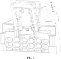
- the guide pillars when the test tool is operated to plug the profiling connector in the socket, the guide pillars are plugged in the guide jacks on the module frame of the battery module first, so as to enable guidance for inserting the profiling connector into the socket, thus providing the effect of facilitating plugging.
- the hook at the second end of the second operating body is clamped with the module frame of the battery module, and under the effect of the elastic member, elastic force acts on the first operating body and the second operating body respectively, so that the profiling connector at the second end of the first operating body is inserted into the socket, and the hook of the second operating body is clamped with the module frame, so that the first operating body and the second operating body are in a state of gripping the module frame, and then the test tool with the profiling connector and the battery module are in a state of relatively stable connection, thereby ensuring stable connection between the profiling connector and the socket.
- a hinge block is connected with a first side face of the first operating body, the first end of the hinge block is aligned with the second end of the first operating body and is provided with a first hinge ring, and the second operating body is provided with a second hinge ring, the first hinge ring and the second hinge ring being hinged via a rotating shaft.
- two hinge blocks are provided and are arranged at an interval;
- the second operating body includes two connecting legs, the two connecting legs are each provided with a second hinge ring, and the hook is arranged at a first end of the connecting leg;
- the two second hinge rings are respectively hinged with the first hinge rings of the two hinge blocks.
- the second operating body with the connecting legs facilitates the arrangement of the hook and clamping of the hook to the module frame, and the second operating body in the form of connecting legs can reduce weight and facilitate operation.
- the second operating body further includes a crossbar, and two ends of the crossbar are respectively connected with the second ends of the two connecting legs to form a structure for hand-holding.
- the frame-shaped second operating body formed of the crossbar and the two connecting legs is easy to hold with hand.
- the test tool with a profiling connector further includes: two abutting blocks, where the first ends of the two abutting blocks are respectively connected with the second end of the first operating body, and the second ends thereof extend in a direction toward the connecting legs and abut against the connecting legs; in which the two guide pillars are respectively connected with the two abutting blocks.
- the two abutting blocks can protect the guide pillars to prevent the connecting legs of the second operating body from abutting against the guide pillars when the tooling is not operating, i.e., in the initial state, which causes deformation of the guide pillars and affects the guiding accuracy.
- the elastic member is an elastic plunger, a spring or a leaf spring.
- the test tool with a profiling connector further includes: a first fastener that is connected with the first operating body, has an accommodating space in the middle, and has a plurality of jacks communicating with the accommodating space at its first end;
- the profiling connector is connected with the first end of the first fastener, and the elastic probe extends into the accommodating space through the jack.
- the profiling connector With the arrangement of the first fastener, it is easy to connect the profiling connector with the first operating body, meanwhile, an accommodating space is provided in the first fastener, which can facilitate connection of the elastic probe of the profiling connector to the wire of the testing equipment.
- the first fastener is connected with a side face of the first operating body facing the second operating body, the first end of the first fastener is aligned with the second end of the first operating body, and a lead wire channel communicating with the accommodating space is provided at the second end of the first fastener opposite to the first end.
- the test tool with a profiling connector further includes:
- the second fastener is provided to fasten the profiling connector to the first fastener by clamping, which facilitates subsequent disassembly and maintenance.
- steps are provided on opposite sides of the first end of the first fastener, a groove is provided at the tail end of the profiling connector, and the groove is mated with the steps; and a stepped block protruding from one side of the tail end of the profiling connector forms a first clamping portion, and the second clamping portion is a clamping slot on the second fastener.
- connection between the profiling connector and the first fastener is simple and convenient, and the clamping between the profiling connector and the second fastener is convenient and fast and the clamping structure is simple and easy to form, enabling desirable stability after connection.
- the invention of the present application further concerns : a battery testing method using the test tool with a profiling connector described above; the battery testing method specifically includes:
- the first end of the operating portion can be used for hand-holding, and a profiling connector is provided at the second end of the operating portion, so as to avoid directly operating the connector with a small structure by hand.
- the profiling connector can be inserted into the socket to be detected and plugged by holding the operating portion with hand, so that the staff can conveniently apply force to plug the profiling connector in the socket, and the force application at this time is done by the whole hand instead of fingers acting on the connector, which solves the problem of injury to fingers of the staff effectively.
- an elastic probe is provided in the jack of the profiling connector, and after the profiling connector is inserted into the socket to be detected and plugged, the elastic probe elastically abuts against the probe of the socket, thus changing the original sliding friction between the probe of the connector and the probe of the socket into elastic abutment, effectively avoiding damage to the profiling connector caused by repeated plugging and unplugging, improving the service life and reducing the usage cost.
- an embodiment means that a particular feature, structure, or characteristic described in connection with the embodiment can be included in at least one embodiment of the present application.
- the appearance of this phrase in various places in the specification does not necessarily refer to the same embodiment, nor does it refer to a separate or alternative embodiment that is mutually exclusive with other embodiments. It is explicitly and implicitly understood by those skilled in the art that the embodiments described herein may be combined with other embodiments.
- the term "and/or" is only an associative relationship for describing associated objects, indicating that there may be three relationships.
- a and/or B may represent three cases: A alone, both A and B, and B alone.
- the character "/" herein generally means that the associated objects before and after it are in an "or" relationship.
- a plurality of refers to two or more (including two), and similarly, “multiple groups” refers to two or more (including two) groups, and “multiple sheets” refers to two or more (including two) sheets.
- the technical terms “mount”, “join”, “connect”, “fix”, etc. should be understood in a broad sense, such as, a fixed connection, a detachable connection, or an integral connection; a mechanical connection, or an electrical connection; a direct connection, an indirect connection through an intermediate medium, an internal communication between two elements, or interaction between two elements.
- the specific meanings of the above terms in the embodiments of the present application can be understood according to specific situations.
- the power batteries are used in energy storage power source systems such as hydraulic, thermal, wind and solar power stations as well as in electric vehicles such as electric bicycles, electric motorcycles and electric cars, and military equipment and aerospace fields. With the continuous expansion of the application field of the power batteries, the market demand is also constantly expanding.
- the power batteries should not only have good power storage and discharge functions, but also ensure safe operation during work, that is, it is necessary to ensure that the voltage and temperature of the battery module in the power batteries are within a safe range during operation. Therefore, a standard socket capable of collecting voltage and temperature is provided on the battery module, and the voltage and temperature of the battery module can be detected in real time by connection with the socket. To ensure the safety of the battery module during operation, it is necessary to detect the voltage and temperature of the battery module when it is working, that is, when charging and discharging, and to detect the effect of connection of the socket with the battery module before the power battery leaves the factory.
- the detection of the voltage and temperature of the battery module before leaving the factory includes plugging a standard connector that matches the socket in the socket, then obtaining the voltage and temperature of the battery module during operation through the detection settings, and determining whether the socket is effectively connected with the battery module.
- an easy-to-operate tooling can be designed to carry out the operation of plugging the above-mentioned connector in the socket, so as to solve the problem that existing connector plugging causes injury to the fingers of the staff; meanwhile, a profiling connector of a long service life can be provided in the tool.
- the shell is made of wear-resistant materials, and an elastic probe is provided in the profiling connector to convert the sliding friction contact between the probe of the connector and the probe of the socket into elastic abutment contact, thereby solving the problem of increased usage costs due to insufficient service life of the connector.
- the test tool with a profiling connector disclosed in the embodiment of the present application is used in enterprises for mass-production of batteries as well as in enterprises for non-mass production of batteries, and also in enterprises that produce other electronic products, as long as it is used in a working environment involving repeated plugging and unplugging of a connector in and out of a socket for testing.
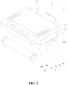
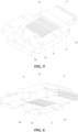
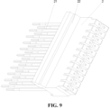
- an embodiment of the present application provides a test tool with a profiling connector, including: an operating portion 1, a first end of the operating portion 1 being used for hand-holding; a profiling connector 2 adapted to a socket 7 to be detected and plugged, where an elastic probe 21 is provided in the jack of the profiling connector 2, and the profiling connector 2 is arranged at a second end of the operating portion 1 opposite to the first end.
- the profiling connector 2 can be inserted into the socket 7 by holding the operating portion 1 with hand, with the elastic probe 21 abutting against and electrically connected with a probe of the socket 7.
- the operating portion 1 is the portion for the staff to operate of the test tool with a profiling connector in the embodiment of the present application.
- the operating portion 1 may be made of metal materials, such as stainless steel, aluminum alloy, magnesium alloy, etc., and may also be made of plastic materials meeting the use strength requirement.
- the holding structure at the first end of the operating portion 1 may be provided with a ring-shaped handle, a rod-shaped handle, or the like, and the connection between the second end of the operating portion 1 and the profiling connector 2 may be made through bolt connection or through clamping with a clamping structure.
- the profiling connector 2 is so called because the shape and structure of the profiling connector 2 can be adapted according to the structure of the socket 7 to be detected and plugged, so as to meet the requirements of plugging and matching of sockets 7 with various structures.
- the profiling connector 2 may be made of friction-resistant materials, such as polyetheretherketone.
- an elastic probe 21 that is commercially available is used as the probe in the jack of the profiling connector 2.
- the elastic probe 21 can be elastically deformed upon contact with the probe of the socket 7 and then maintain the state of elastic abutment, thereby converting the original sliding plugging between the probes into elastic abutment connection.
- the elastic probe 21 of the profiling connector 2 can be electrically connected with the detection equipment through connection wires, so as to send the voltage and temperature signals obtained through detection to the detection equipment.
- the first end of the operating portion 1 can be used for hand-holding, and a profiling connector 2 is provided at the second end of the operating portion 1, so as to avoid directly operating the connector with a small structure by hand.
- the profiling connector 2 can be inserted into the socket 7 to be detected and plugged by holding the operating portion 1 with hand, so that the staff can conveniently apply force to plug the profiling connector 2 in the socket 7, and the force application at this time is done by the whole hand instead of fingers acting on the connector, which solves the problem of injury to fingers of the staff effectively.
- an elastic probe 21 is provided in the jack of the profiling connector 2, and after the profiling connector 2 is inserted into the socket 7 to be detected and tested, the elastic probe 21 elastically abuts against the probe of the socket 7, thus changing the original sliding friction between the probe of the connector and the probe of the socket 7 into elastic abutment, effectively avoiding damage to the profiling connector 2 caused by repeated plugging and unplugging, improving the service life and reducing the usage cost.
- the test tool with a profiling connector further includes two guide pillars 3 connected with the second end of the operating portion 1 respectively, and the two guide pillars 3 are respectively arranged on two sides of the profiling connector 2.
- the guide pillar 3 may be a cylinder, and the distance by which the guide pillar 3 protrudes from the end portion of the second end of the operating portion 1 is greater than the distance by which the profiling connector 2 protrudes from the end portion of the second end of the operating portion 1, so that when the staff plugs the profiling connector 2 in the socket 7 by holding the operating portion 1, as shown in Fig. 4 , the two guide pillars 3 are first plugged in the guide holes on the module frame 8 of the battery module (which may be the original process holes on the module frame 8), and then provide guidance for inserting the profiling connector 2 into the socket 7. It should be noted that there are preferably two guide pillars 3 that are distributed on two sides of the profiling connector 2 in order to achieve a good guiding effect.
- the guide pillars 3 when the tooling is operated to plug the profiling connector 2 in the socket 7, the guide pillars 3 are plugged in the guide jacks on the module frame 8 of the battery module first, so as to achieve guidance for inserting the profiling connector 2 into the socket 7, providing the effect of facilitating plugging.
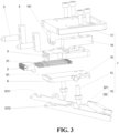
- the operating portion 1 includes: a first operating body 11, a second operating body 12 and an elastic member 13; the first end of the first operating body 11 is used for hand-holding, and the second end is provided with the profiling connector 2; the first end of the second operating body 12 is used for hand-holding, and the second end is provided with a hook 1211, and the position of the second operating body 12 near the second end is hinged with the second end of the first operating body 11, and the hook 1211 is used to be clamped with the battery module when the profiling connector 2 is inserted into the socket 7; the elastic member 13 is arranged between the first operating body 11 and the second operating body 12 so that a preset included angle is formed between the first operating body 11 and the second operating body 12, and is used to provide resilience.
- the combination of the first operating body 11, the second operating body 12 and the elastic member 13 forms a gripping body structure capable of elastic resilience.
- the first end of the first operating body 11 may be provided as a ring-shaped structure, or a rod-shaped structure that is convenient to hand-hold, or a structure similar to other existing handle structures that are convenient to hand-hold.
- the connection between the second end and the profiling connector 2 may be connection through bolts or may be clamping connection.
- the clamping connection may include clamping the profiling connector 2 with a clamping ring provided at the second end of the first operating body 11, or by clamping of a clamping block provided on the profiling connector 2 to a clamping slot provided at the second end of the first operating body 11.
- the first end of the second operating body 12 may be provided to have the same structure as the first end of the first operating body 11, as long as it is convenient to hand-hold, and details thereof will not be repeated here.
- the hook 1211 at the second end of the second operating body 12 may be a hook 1211 in the form of a groove matching the hole in the module frame 8 of the battery module.
- the elastic member 13 may be any form of component that generates an elastic abutting force, such as an elastic plunger, a spring, a leaf spring, or the like, and the elastic member 13 can be arranged between the first operating body 11 and the second operating body 12 by conventional means.
- an elastic plunger such as an elastic plunger, a spring, a leaf spring, or the like
- the elastic member 13 can be arranged between the first operating body 11 and the second operating body 12 by conventional means.
- the operator when inserting the profiling connector 2 into the socket 7 in the embodiment of the present application, the operator can apply a gripping force to the first operating body 11 and the second operating body 12, so that the first operating body 11 and the second operating body 12 rotate and approach relative to each other. At this time, the hook 1211 at the second end of the second operating body 12 is relatively far away from the profiling connector 2.
- the staff plugs the profiling connector 2 in the socket 7 by holding the first operating portion 1, the staff can release the gripping force applied to the first operating body 11 and the second operating body 12, and the hook 1211 at the second end of the second operating body 12 is clamped with the module frame 8 of the battery module.
- the elastic force acts on the first operating body 11 and the second operating body 12 respectively, so that the profiling connector 2 at the second end of the first operating body 11 is inserted into the socket 7, with the hook 1211 of the second operating body 12 being clamped with the module frame 8, so that the first operating body 11 and the second operating body 12 are in a state of gripping the module frame 8, and then the test tool with the profiling connector and the battery module are in a state of relatively stable connection, thereby ensuring stable connection between the profiling connector 2 and the socket 7.
- a hinge block 14 is connected with a first side face of the first operating body 11, the first end of the hinge block 14 is aligned with the second end of the first operating body 11 and is provided with a first hinge ring 141, and the second operating body 12 is provided with a second hinge ring 1212, the first hinge ring 141 and the second hinge ring 1212 being hinged via a rotating shaft 15.
- the arrangement of the hinge block 14 can simplify the structure of the first operating body 11.
- the first operating body 11 can be provided in a plate shape as a whole, and then the hinge block 14 is connected with the first side face of the operating body 11 through bolt connection.
- the second hinge ring 1212 is provided on the second operating body 12, hinging of the first operating body 11 with the second operating body 12 can be realized conveniently and quickly.
- the second operating body 12 includes two connecting legs 121, the second hinge rings 1212 are respectively arranged on the two connecting legs 121, and the hooks 1211 are arranged at the first ends of the connecting legs 121.
- the two second hinge rings 1212 are respectively hinged with the first hinge rings 141 of the two hinge blocks 14.
- the second operating body 12 further includes a crossbar 122, and two ends of the crossbar are respectively connected with the second ends of the two connecting legs to form a structure for hand-holding.
- the second operating body 12 is provided in a frame shape formed of a crossbar 122 and two connecting legs 121, so that the crossbar 122 is convenient for the staff to hand-hold, and the first ends of the two connecting legs 121 are convenient for providing the hook 1211, while the two separate connecting legs 121 facilitate the clamping connection between the hook 1211 and the module frame 8.
- the second operating body 12 in the form of connecting legs 121 can reduce weight and facilitate operation.
- a suitable distance is kept between the two connecting legs 121, so that the two connecting legs 121 can be arranged directly facing the two guide pillars 3.
- the profiling connector 2 is inserted into the socket 7, and the hook 1211 of the connecting leg 121 is clamped with the module frame 8, under the action of the elastic member 13, the first operating body 11 and the second operating body 12 are in a state of gripping the module frame 8, and then the test tool with the profiling connector and the battery module are in a state of relatively stable connection, thereby ensuring stable connection between the profiling connector 2 and the socket 7.
- the test tool with a profiling connector further includes:
- the first ends of the two abutting blocks 4 are respectively connected with the second end of the first operating body 11, and the second ends thereof extend in a direction toward the connecting legs 121 and abut against the connecting legs 121.
- the two guide pillars 3 are respectively connected with the two abutting blocks 4.
- the two abutting blocks 4 can be connected with the second end of the first operating body 11 by bolts, and the two guide pillars 3 can be arranged in the preset connection holes or slots of the two abutting blocks 4 by way of interference fit.
- the two abutting blocks 4 can protect the guide pillars 3 to prevent the connecting legs 121 of the second operating body 12 from abutting against the guide pillars 3 when the tooling is not operating, i.e., in the initial state, which causes deformation of the guide pillars 3 and affects the guiding accuracy.
- the test tool with a profiling connector further includes: a first fastener 5 that is connected with the first operating body 11, has an accommodating space 51 in the middle, and has a plurality of jacks 52 communicating with the accommodating space 51 at its first end.
- the profiling connector 2 is connected with the first end of the first fastener 5, and the elastic probe 21 extends into the accommodating space 51 through the jack 52.
- the first operating body 11 may be in the shape of a plate as a whole, and the first fastener 5 may also be in the shape of a plate as a whole, so as to facilitating connection of the two.
- the connection between the two may be connection through bolts.
- the accommodating space 51 provided on the first fastener 5 may be a groove provided on a side face of the first fastening body of the plate body structure, or a hollow that runs through both side faces.
- the distribution pattern of the plurality of jacks 52 provided at the first end of the first fastener 5 needs to match with the distribution pattern of the jacks of the profiling connector 2.
- the arrangement of the first fastener 5 facilitates connection of the profiling connector 2 with the first operating body 11, while the accommodating space 51 is provided in the first fastener 5, which can facilitate connection of the elastic probe 21 of the profiling connector 2 with the wire of the testing equipment.
- the test tool with a profiling connector further includes: a second fastener 6 connected with the first fastener 5.
- the first end of the first fastener 5 is inserted to and mated with the tail end of the profiling connector 2
- a first clamping portion 22 is provided on one side of the profiling connector 2
- a second clamping portion 61 is provided on the second fastener 6, and the first clamping portion 22 is clamped with the second clamping portion 61.
- the second fastener 6 can be adapted to the first fastener 5, that is, when the first fastener 5 is in the shape of a plate as a whole, the second fastener 6 may also be provided in a plate shape and then be connected with the first fastener 5 by bolt fixing.
- the second fastener 6 is provided to fasten the profiling connector 2 to the first fastener 5 by clamping, which is convenient for subsequent disassembly and maintenance.
- steps 54 are provided on opposite sides of the first end of the first fastener 5, and a groove 23 is provided at the tail end of the profiling connector 2, and the groove 23 is mated with the steps 54.
- a stepped block protruding from one side of the tail end of the profiling connector 2 forms a first clamping portion 22, and the second clamping portion 61 is a clamping slot on the second fastener 6.
- connection between the profiling connector 2 and the first fastener 5 is simple and convenient, and the clamping between the profiling connector 2 and the second fastener 6 is convenient and fast, and the clamping structure is simple and easy to form, enabling desirable stability after connection.
- the embodiment of the present application provides a battery testing method using the above-mentioned test tool with a profiling connector.
- the battery testing method specifically includes:
- the first end of the operating portion 1 can be used for hand-holding, and a profiling connector 2 is provided at the second end of the operating portion 1, so as to avoid directly operating the connector with a small structure by hand.
- the profiling connector 2 can be inserted into the socket 7 to be detected and plugged by holding the operating portion 1 with hand, so that the staff can conveniently apply force to plug the profiling connector 2 in the socket 7, and the force application at this time is done by the whole hand instead of fingers acting on the connector, which solves the problem of injury to fingers of the staff effectively.
- an elastic probe 21 is provided in the jack of the profiling connector 2, and after the profiling connector 2 is inserted into the socket 7 to be detected and plugged, the elastic probe 21 elastically abuts against the probe of the socket 7, thus changing the original sliding friction between the probe of the connector and the probe of the socket 7 into elastic abutment, effectively avoiding damage to the profiling connector 2 caused by repeated plugging and unplugging, improving the service life and reducing the usage cost.
Landscapes
- Physics & Mathematics (AREA)
- General Physics & Mathematics (AREA)
- Engineering & Computer Science (AREA)
- Manufacturing & Machinery (AREA)
- Chemical & Material Sciences (AREA)
- Chemical Kinetics & Catalysis (AREA)
- Electrochemistry (AREA)
- General Chemical & Material Sciences (AREA)
- Measuring Leads Or Probes (AREA)
- Details Of Connecting Devices For Male And Female Coupling (AREA)
Claims (12)
- Prüfwerkzeug mit profiliertem Verbinder (2), aufweisend:einen Betätigungsabschnitt (1), wobei ein erstes Ende des Betätigungsabschnitts (1) zum Halten in einer Hand verwendet wird; undeinen profilierten Verbinder (2), der zum Einstecken in eine zu messende Buchse (7) angepasst ist, gekennzeichnet dadurch, dass eine elastische Sonde (21) in einer Steckbuchse (52) des profilierten Verbinders (2) angeordnet ist und der profilierte Verbinder (2) an einem zweiten Ende des Betätigungsabschnitts (1) gegenüber dem ersten Ende angeordnet ist;wobei der profilierte Verbinder (2) durch Halten des Betätigungsabschnitts (1) mit der Hand in die Buchse (7) einführbar ist und die elastische Sonde (21) an einer Sonde der Buchse (7) anliegt und elektrisch mit ihr verbunden ist; wobeider Betätigungsabschnitt (1) aufweist:einen ersten Betätigungskörper (11), einen zweiten Betätigungskörper (12) und ein elastisches Element;wobei ein erstes Ende des ersten Betätigungskörpers (11) zum Halten in der Hand verwendet wird und ein zweites Ende davon mit dem profilierten Verbinder (2) versehen ist;ein erstes Ende des zweiten Betätigungskörpers (12) zum Halten in der Hand verwendet wird und ein zweites Ende davon mit einem Haken (1211) versehen ist, wobei die Position des zweiten Betätigungskörpers (12) nahe dem zweiten Ende mit dem zweiten Ende des ersten Betätigungskörpers (11) scharniert ist und der Haken (1211) zum Klemmen an ein Batteriemodul verwendet wird, wenn der profilierte Verbinder (2) in die Buchse (7) eingeführt wird; unddas elastische Element (13) zwischen dem ersten Betätigungskörper (11) und dem zweiten Betätigungskörper (12) angeordnet ist, sodass ein voreingestellter eingeschlossener Winkel zwischen dem ersten Betätigungskörper (11) und dem zweiten Betätigungskörper (12) gebildet wird, und dazu verwendet wird, um Elastizität bereitzustellen.
- Prüfwerkzeug mit profiliertem Verbinder (2) nach Anspruch 1, ferner aufweisend:
zwei Führungssäulen (3), die jeweils mit dem zweiten Ende des Betätigungsabschnitts (1) verbunden sind und die beiderseits des profilierten Verbinders (2) angeordnet sind. - Prüfwerkzeug mit profiliertem Verbinder (2) nach Anspruch 1, wobei
ein Scharnierblock (14) mit einer ersten Seitenfläche des ersten Betätigungskörpers (11) verbunden ist, das erste Ende des Scharnierblocks (14) mit dem zweiten Ende des ersten Betätigungskörpers (11) ausgerichtet und mit einem ersten Scharnierring (141) versehen ist, der zweite Betätigungskörper (12) mit einem zweiten Scharnierring (1212) versehen ist und der erste Scharnierring (141) und der zweite Scharnierring (1212) über eine Drehachse (15) scharniert sind. - Prüfwerkzeug mit profiliertem Verbinder (2) nach Anspruch 3, wobeizwei Scharnierblöcke (14) bereitgestellt und zueinander beabstandet angeordnet sind;wobei der zweite Betätigungskörper (12) zwei Verbindungsbeine (121) aufweist, die zwei Verbindungsbeine (121) jeweils mit dem zweiten Scharnierring (1212) versehen sind und der Haken (1211) an einem ersten Ende des Verbindungsbeins (121) angeordnet ist;wobei die zwei zweiten Scharnierringe (1212) jeweils mit dem ersten Scharnierring (141) der zwei Scharnierblöcke (14) scharniert sind.
- Prüfwerkzeug mit profiliertem Verbinder (2) nach Anspruch 4, wobei
der zweite Betätigungskörper (12) ferner eine Querstange (122) aufweist und zwei Enden der Querstange (122) mit dem zweiten Ende der zwei Verbindungsbeine (121) verbunden sind, um eine Struktur zum Halten in der Hand zu bilden. - Prüfwerkzeug mit profiliertem Verbinder (2) nach Anspruch 4 oder 5, ferner aufweisend:zwei Anliegeblöcke (4), wobei erste Enden der zwei Anliegeblöcke (4) jeweils mit dem zweiten Ende des ersten Betätigungskörpers (11) verbunden sind und ihre zweiten Enden sich in Richtung der Verbindungsbeine (121) erstrecken und an den Verbindungsbeinen (121) anliegen;wobei die zwei Führungssäulen (3) mit den zwei Anliegeblöcken (4) verbunden sind.
- Prüfwerkzeug mit profiliertem Verbinder (2) nach einem der Ansprüche 1-4, wobei
das elastische Element (13) ein elastischer Kolben, eine Feder oder eine Blattfeder ist. - Prüfwerkzeug mit profiliertem Verbinder (2) nach Anspruch 1, ferner aufweisend:ein erstes Befestigungselement (5), das mit dem ersten Betätigungskörper (11) verbunden ist, in der Mitte einen Aufnahmeraum (51) aufweist und an seinem ersten Ende mehrere Steckbuchsen (52) aufweist, die kommunizierend mit dem Aufnahmeraum (51) verbunden sind;wobei der profilierte Verbinder (2) mit dem ersten Ende des ersten Befestigungselements (5) verbunden ist und die elastische Sonde (21) sich durch die Steckbuchse (52) in den Aufnahmeraum (51) erstreckt.
- Prüfwerkzeug mit profiliertem Verbinder (2) nach Anspruch 8, wobei
das erste Befestigungselement (5) mit einer Seitenfläche des ersten Betätigungskörpers (11) verbunden ist, die dem zweiten Betätigungskörper (12) zugewandt ist, das erste Ende des ersten Befestigungselements (5) mit dem zweiten Ende des ersten Betätigungskörpers (11) ausgerichtet ist und ein Leitungskanal (53), der kommunizierend mit dem Aufnahmeraum (51) verbunden ist, an einem zweiten Ende des ersten Befestigungselements (5) gegenüber dem ersten Ende bereitgestellt ist. - Prüfwerkzeug mit profiliertem Verbinder (2) nach Anspruch 8 oder 9, ferner aufweisend:ein zweites Befestigungselement (6), das mit dem ersten Befestigungselement (5) verbunden ist;wobei das erste Ende des ersten Befestigungselements (5) in das hintere Ende des profilierten Verbinders (2) eingeführt und damit gepaart ist, ein erster Klemmabschnitt (22) auf einer Seite des profilierten Verbinders (2) bereitgestellt ist und ein zweiter Klemmabschnitt (61) auf dem zweiten Befestigungselement (6) bereitgestellt ist, wobei der erste Klemmabschnitt (22) an den zweiten Klemmabschnitt (61) geklemmt ist.
- Prüfwerkzeug mit profiliertem Verbinder (2) nach Anspruch 10, wobeiStufen (54) auf gegenüberliegenden Seiten des ersten Endes des ersten Befestigungselements (5) bereitgestellt sind, eine Nut (23) an dem hinteren Ende des profilierten Verbinders (2) bereitgestellt ist und die Nut (23) mit den Stufen (54) gepaart ist;ein Stufenblock, der von einer Seite des hinteren Endes des profilierten Verbinders (2) hervorsteht, den ersten Klemmabschnitt (22) bildet und der zweite Klemmabschnitt (61) ein Klemmschlitz an dem zweiten Befestigungselement (6) ist.
- Batterieprüfverfahren, in welchem das Prüfwerkzeug mit profiliertem Verbinder (2) nach einem der Ansprüche 1-11 verwendet wird; wobei das Batterieprüfverfahren insbesondere umfasst:Bereitstellen einer Batterie mit einer Buchse (7); undEinführen des profilierten Verbinders (2) in die Buchse (7) durch Halten des Betätigungsabschnitts (1) mit der Hand, wobei die elastische Sonde (21) an einer Sonde der Buchse (7) anliegt und elektrisch mit ihr verbunden ist.
Applications Claiming Priority (2)
| Application Number | Priority Date | Filing Date | Title |
|---|---|---|---|
| CN202122495588.0U CN216213672U (zh) | 2021-10-15 | 2021-10-15 | 具有仿形连接器的测试工装 |
| PCT/CN2022/124618 WO2023061362A1 (zh) | 2021-10-15 | 2022-10-11 | 具有仿形连接器的测试工装及电池测试方法 |
Publications (4)
| Publication Number | Publication Date |
|---|---|
| EP4325629A1 EP4325629A1 (de) | 2024-02-21 |
| EP4325629A4 EP4325629A4 (de) | 2024-09-18 |
| EP4325629B1 true EP4325629B1 (de) | 2025-06-04 |
| EP4325629C0 EP4325629C0 (de) | 2025-06-04 |
Family
ID=80883074
Family Applications (1)
| Application Number | Title | Priority Date | Filing Date |
|---|---|---|---|
| EP22880299.7A Active EP4325629B1 (de) | 2021-10-15 | 2022-10-11 | Prüfwerkzeug mit profilierungsverbinder und batterieprüfverfahren |
Country Status (4)
| Country | Link |
|---|---|
| US (1) | US12517150B2 (de) |
| EP (1) | EP4325629B1 (de) |
| CN (1) | CN216213672U (de) |
| WO (1) | WO2023061362A1 (de) |
Families Citing this family (3)
| Publication number | Priority date | Publication date | Assignee | Title |
|---|---|---|---|---|
| CN216213672U (zh) * | 2021-10-15 | 2022-04-05 | 宁德时代新能源科技股份有限公司 | 具有仿形连接器的测试工装 |
| CN116718957B (zh) * | 2023-08-07 | 2023-10-20 | 深圳市西点精工技术有限公司 | 一种高速连接器用自动化测试设备 |
| CN118011282B (zh) * | 2024-03-25 | 2024-06-11 | 泰兴市航顺电子有限公司 | 一种矩形连接器连接测试装置 |
Family Cites Families (14)
| Publication number | Priority date | Publication date | Assignee | Title |
|---|---|---|---|---|
| US4360780A (en) * | 1981-10-30 | 1982-11-23 | Skutch Jr William G | Dual voltage battery tester |
| DE59101876D1 (de) * | 1991-04-10 | 1994-07-14 | Callahan George Edgar | Verfahren und Vorrichtung zum Prüfen des Ladezustands von Starterbatterien. |
| US6254438B1 (en) * | 1999-10-21 | 2001-07-03 | Snap-On Tools Company | Battery side-terminal adapter and Kelvin connector |
| DE10024875B4 (de) * | 2000-05-16 | 2004-07-01 | Infineon Technologies Ag | Bauteilhaltersystem zur Verwendung mit Testvorrichtungen zum Testen elektronischer Bauteile |
| US6828796B2 (en) * | 2003-02-27 | 2004-12-07 | Lue Vang | Electrical continuity tester |
| US10222397B2 (en) * | 2014-09-26 | 2019-03-05 | Midtronics, Inc. | Cable connector for electronic battery tester |
| TWI599779B (zh) * | 2016-07-11 | 2017-09-21 | 致茂電子股份有限公司 | 夾式探針裝置 |
| CN206163779U (zh) * | 2016-11-18 | 2017-05-10 | 深圳市得润电子股份有限公司 | 插头连接器和插座连接器 |
| US11460504B2 (en) * | 2018-08-27 | 2022-10-04 | Chaojiong Zhang | Multi-chamber, explosion-proof, battery-testing apparatus |
| CN209387805U (zh) * | 2018-12-27 | 2019-09-13 | 上海纪岩电力科技有限公司 | 一种高压电缆接头耐压检测设备 |
| CN112710960B (zh) * | 2019-10-25 | 2024-04-26 | 上海沃尔沃汽车研发有限公司 | 用于动力电池测试的集成式msd连接器测试盒 |
| CN212160026U (zh) * | 2020-01-19 | 2020-12-15 | 赣州亿鹏能源科技有限公司 | 简易电池模组检测卡 |
| CN213364819U (zh) * | 2020-08-08 | 2021-06-04 | 武汉特尔斯特汽车技术科技有限公司 | 一种新能源电池测试线束 |
| CN216213672U (zh) * | 2021-10-15 | 2022-04-05 | 宁德时代新能源科技股份有限公司 | 具有仿形连接器的测试工装 |
-
2021
- 2021-10-15 CN CN202122495588.0U patent/CN216213672U/zh active Active
-
2022
- 2022-10-11 WO PCT/CN2022/124618 patent/WO2023061362A1/zh not_active Ceased
- 2022-10-11 EP EP22880299.7A patent/EP4325629B1/de active Active
-
2023
- 2023-12-07 US US18/532,886 patent/US12517150B2/en active Active
Also Published As
| Publication number | Publication date |
|---|---|
| EP4325629A4 (de) | 2024-09-18 |
| US20240103039A1 (en) | 2024-03-28 |
| US12517150B2 (en) | 2026-01-06 |
| WO2023061362A1 (zh) | 2023-04-20 |
| CN216213672U (zh) | 2022-04-05 |
| EP4325629C0 (de) | 2025-06-04 |
| EP4325629A1 (de) | 2024-02-21 |
Similar Documents
| Publication | Publication Date | Title |
|---|---|---|
| EP4325629B1 (de) | Prüfwerkzeug mit profilierungsverbinder und batterieprüfverfahren | |
| CN212483790U (zh) | 适用于不同尺寸规格的电池充放电测量装置 | |
| CN209233050U (zh) | 一种用于大电流电池包的连接器 | |
| CN218867535U (zh) | 一种便于插拔的连接器 | |
| CN108054609A (zh) | 试验端子短接装置 | |
| CN108557093B (zh) | 一种多旋翼无人机巡检系统快速换装装置 | |
| CN212783914U (zh) | 连接器、新能源汽车和充换电站 | |
| CN219759883U (zh) | 电池模块、电池及用电设备 | |
| CN220752170U (zh) | 一种电芯夹具 | |
| CN110911595A (zh) | 一种电池模组数据采集结构及具有该结构的电池模组 | |
| CN117458176B (zh) | 一种电力设备线夹 | |
| CN219086177U (zh) | 一种锂电池极柱连接结构、电池模组及电池包 | |
| EP4279927B1 (de) | Testklammer und testvorrichtung | |
| CN218724911U (zh) | 一种电芯极耳折弯、滚平过程极耳受力测试工装 | |
| CN212063579U (zh) | 一种均衡锂电池组中各单体之间电压的设备 | |
| CN113782283A (zh) | 钢帽装卸装置及其辅助组件 | |
| CN202720246U (zh) | 一种测试用电连接器 | |
| CN219758316U (zh) | 测试工装夹具组件及测试设备 | |
| CN212848962U (zh) | 一种电连接件 | |
| CN223967440U (zh) | 一种便于连接的插拔式连接线 | |
| CN219874182U (zh) | 一种输出端口及组装电池 | |
| CN217639179U (zh) | 一种电缆试验快速连接装置 | |
| CN221379606U (zh) | 一种快换电和机械固定通用锂电池 | |
| CN219978379U (zh) | 一种带隔离的电能计量装置表架 | |
| CN220773188U (zh) | 一种配电安全检测装置 |
Legal Events
| Date | Code | Title | Description |
|---|---|---|---|
| STAA | Information on the status of an ep patent application or granted ep patent |
Free format text: STATUS: THE INTERNATIONAL PUBLICATION HAS BEEN MADE |
|
| PUAI | Public reference made under article 153(3) epc to a published international application that has entered the european phase |
Free format text: ORIGINAL CODE: 0009012 |
|
| STAA | Information on the status of an ep patent application or granted ep patent |
Free format text: STATUS: REQUEST FOR EXAMINATION WAS MADE |
|
| 17P | Request for examination filed |
Effective date: 20231115 |
|
| AK | Designated contracting states |
Kind code of ref document: A1 Designated state(s): AL AT BE BG CH CY CZ DE DK EE ES FI FR GB GR HR HU IE IS IT LI LT LU LV MC ME MK MT NL NO PL PT RO RS SE SI SK SM TR |
|
| A4 | Supplementary search report drawn up and despatched |
Effective date: 20240820 |
|
| RIC1 | Information provided on ipc code assigned before grant |
Ipc: G01R 31/385 20190101ALI20240813BHEP Ipc: G01R 1/067 20060101ALI20240813BHEP Ipc: G01R 1/04 20060101ALI20240813BHEP Ipc: H01M 10/48 20060101AFI20240813BHEP |
|
| RAP1 | Party data changed (applicant data changed or rights of an application transferred) |
Owner name: CONTEMPORARY AMPEREX TECHNOLOGY(HONG KONG) LIMITED |
|
| DAV | Request for validation of the european patent (deleted) | ||
| DAX | Request for extension of the european patent (deleted) | ||
| GRAP | Despatch of communication of intention to grant a patent |
Free format text: ORIGINAL CODE: EPIDOSNIGR1 |
|
| STAA | Information on the status of an ep patent application or granted ep patent |
Free format text: STATUS: GRANT OF PATENT IS INTENDED |
|
| RIC1 | Information provided on ipc code assigned before grant |
Ipc: G01R 31/385 20190101ALI20250214BHEP Ipc: G01R 1/067 20060101ALI20250214BHEP Ipc: G01R 1/04 20060101ALI20250214BHEP Ipc: H01M 10/48 20060101AFI20250214BHEP |
|
| INTG | Intention to grant announced |
Effective date: 20250227 |
|
| GRAS | Grant fee paid |
Free format text: ORIGINAL CODE: EPIDOSNIGR3 |
|
| GRAA | (expected) grant |
Free format text: ORIGINAL CODE: 0009210 |
|
| STAA | Information on the status of an ep patent application or granted ep patent |
Free format text: STATUS: THE PATENT HAS BEEN GRANTED |
|
| AK | Designated contracting states |
Kind code of ref document: B1 Designated state(s): AL AT BE BG CH CY CZ DE DK EE ES FI FR GB GR HR HU IE IS IT LI LT LU LV MC ME MK MT NL NO PL PT RO RS SE SI SK SM TR |
|
| REG | Reference to a national code |
Ref country code: GB Ref legal event code: FG4D |
|
| REG | Reference to a national code |
Ref country code: CH Ref legal event code: EP |
|
| REG | Reference to a national code |
Ref country code: DE Ref legal event code: R096 Ref document number: 602022015668 Country of ref document: DE |
|
| REG | Reference to a national code |
Ref country code: IE Ref legal event code: FG4D |
|
| U01 | Request for unitary effect filed |
Effective date: 20250626 |
|
| U07 | Unitary effect registered |
Designated state(s): AT BE BG DE DK EE FI FR IT LT LU LV MT NL PT RO SE SI Effective date: 20250703 |
|
| PG25 | Lapsed in a contracting state [announced via postgrant information from national office to epo] |
Ref country code: ES Free format text: LAPSE BECAUSE OF FAILURE TO SUBMIT A TRANSLATION OF THE DESCRIPTION OR TO PAY THE FEE WITHIN THE PRESCRIBED TIME-LIMIT Effective date: 20250604 |
|
| PG25 | Lapsed in a contracting state [announced via postgrant information from national office to epo] |
Ref country code: GR Free format text: LAPSE BECAUSE OF FAILURE TO SUBMIT A TRANSLATION OF THE DESCRIPTION OR TO PAY THE FEE WITHIN THE PRESCRIBED TIME-LIMIT Effective date: 20250905 Ref country code: NO Free format text: LAPSE BECAUSE OF FAILURE TO SUBMIT A TRANSLATION OF THE DESCRIPTION OR TO PAY THE FEE WITHIN THE PRESCRIBED TIME-LIMIT Effective date: 20250904 |
|
| PG25 | Lapsed in a contracting state [announced via postgrant information from national office to epo] |
Ref country code: PL Free format text: LAPSE BECAUSE OF FAILURE TO SUBMIT A TRANSLATION OF THE DESCRIPTION OR TO PAY THE FEE WITHIN THE PRESCRIBED TIME-LIMIT Effective date: 20250604 |
|
| PG25 | Lapsed in a contracting state [announced via postgrant information from national office to epo] |
Ref country code: HR Free format text: LAPSE BECAUSE OF FAILURE TO SUBMIT A TRANSLATION OF THE DESCRIPTION OR TO PAY THE FEE WITHIN THE PRESCRIBED TIME-LIMIT Effective date: 20250604 |
|
| PG25 | Lapsed in a contracting state [announced via postgrant information from national office to epo] |
Ref country code: RS Free format text: LAPSE BECAUSE OF FAILURE TO SUBMIT A TRANSLATION OF THE DESCRIPTION OR TO PAY THE FEE WITHIN THE PRESCRIBED TIME-LIMIT Effective date: 20250904 |
|
| U20 | Renewal fee for the european patent with unitary effect paid |
Year of fee payment: 4 Effective date: 20251021 |
|
| PG25 | Lapsed in a contracting state [announced via postgrant information from national office to epo] |
Ref country code: IS Free format text: LAPSE BECAUSE OF FAILURE TO SUBMIT A TRANSLATION OF THE DESCRIPTION OR TO PAY THE FEE WITHIN THE PRESCRIBED TIME-LIMIT Effective date: 20251004 |
|
| PG25 | Lapsed in a contracting state [announced via postgrant information from national office to epo] |
Ref country code: SM Free format text: LAPSE BECAUSE OF FAILURE TO SUBMIT A TRANSLATION OF THE DESCRIPTION OR TO PAY THE FEE WITHIN THE PRESCRIBED TIME-LIMIT Effective date: 20250604 |
|
| PG25 | Lapsed in a contracting state [announced via postgrant information from national office to epo] |
Ref country code: CZ Free format text: LAPSE BECAUSE OF FAILURE TO SUBMIT A TRANSLATION OF THE DESCRIPTION OR TO PAY THE FEE WITHIN THE PRESCRIBED TIME-LIMIT Effective date: 20250604 |
|
| PG25 | Lapsed in a contracting state [announced via postgrant information from national office to epo] |
Ref country code: SK Free format text: LAPSE BECAUSE OF FAILURE TO SUBMIT A TRANSLATION OF THE DESCRIPTION OR TO PAY THE FEE WITHIN THE PRESCRIBED TIME-LIMIT Effective date: 20250604 |
|
| PLBE | No opposition filed within time limit |
Free format text: ORIGINAL CODE: 0009261 |
|
| STAA | Information on the status of an ep patent application or granted ep patent |
Free format text: STATUS: NO OPPOSITION FILED WITHIN TIME LIMIT |
|
| REG | Reference to a national code |
Ref country code: CH Ref legal event code: L10 Free format text: ST27 STATUS EVENT CODE: U-0-0-L10-L00 (AS PROVIDED BY THE NATIONAL OFFICE) Effective date: 20260416 |