EP4325629B1 - Test tool having profiling connector and battery test method - Google Patents
Test tool having profiling connector and battery test method Download PDFInfo
- Publication number
- EP4325629B1 EP4325629B1 EP22880299.7A EP22880299A EP4325629B1 EP 4325629 B1 EP4325629 B1 EP 4325629B1 EP 22880299 A EP22880299 A EP 22880299A EP 4325629 B1 EP4325629 B1 EP 4325629B1
- Authority
- EP
- European Patent Office
- Prior art keywords
- operating body
- connector
- profiling
- profiling connector
- fastener
- Prior art date
- Legal status (The legal status is an assumption and is not a legal conclusion. Google has not performed a legal analysis and makes no representation as to the accuracy of the status listed.)
- Active
Links
Images


Classifications
-
- G—PHYSICS
- G01—MEASURING; TESTING
- G01R—MEASURING ELECTRIC VARIABLES; MEASURING MAGNETIC VARIABLES
- G01R1/00—Details of instruments or arrangements of the types included in groups G01R5/00 - G01R13/00 and G01R31/00
- G01R1/02—General constructional details
- G01R1/06—Measuring leads; Measuring probes
- G01R1/067—Measuring probes
- G01R1/06711—Probe needles; Cantilever beams; "Bump" contacts; Replaceable probe pins
- G01R1/06716—Elastic
- G01R1/06722—Spring-loaded
-
- G—PHYSICS
- G01—MEASURING; TESTING
- G01R—MEASURING ELECTRIC VARIABLES; MEASURING MAGNETIC VARIABLES
- G01R1/00—Details of instruments or arrangements of the types included in groups G01R5/00 - G01R13/00 and G01R31/00
- G01R1/02—General constructional details
- G01R1/04—Housings; Supporting members; Arrangements of terminals
- G01R1/0408—Test fixtures or contact fields; Connectors or connecting adaptors; Test clips; Test sockets
-
- G—PHYSICS
- G01—MEASURING; TESTING
- G01R—MEASURING ELECTRIC VARIABLES; MEASURING MAGNETIC VARIABLES
- G01R1/00—Details of instruments or arrangements of the types included in groups G01R5/00 - G01R13/00 and G01R31/00
- G01R1/02—General constructional details
- G01R1/06—Measuring leads; Measuring probes
- G01R1/067—Measuring probes
- G01R1/06788—Hand-held or hand-manipulated probes, e.g. for oscilloscopes or for portable test instruments
-
- G—PHYSICS
- G01—MEASURING; TESTING
- G01R—MEASURING ELECTRIC VARIABLES; MEASURING MAGNETIC VARIABLES
- G01R31/00—Arrangements for testing electric properties; Arrangements for locating electric faults; Arrangements for electrical testing characterised by what is being tested not provided for elsewhere
- G01R31/36—Arrangements for testing, measuring or monitoring the electrical condition of accumulators or electric batteries, e.g. capacity or state of charge [SoC]
- G01R31/385—Arrangements for measuring battery or accumulator variables
- G01R31/3865—Arrangements for measuring battery or accumulator variables related to manufacture, e.g. testing after manufacture
-
- H—ELECTRICITY
- H01—ELECTRIC ELEMENTS
- H01M—PROCESSES OR MEANS, e.g. BATTERIES, FOR THE DIRECT CONVERSION OF CHEMICAL ENERGY INTO ELECTRICAL ENERGY
- H01M10/00—Secondary cells; Manufacture thereof
- H01M10/42—Methods or arrangements for servicing or maintenance of secondary cells or secondary half-cells
- H01M10/4285—Testing apparatus
-
- H—ELECTRICITY
- H01—ELECTRIC ELEMENTS
- H01M—PROCESSES OR MEANS, e.g. BATTERIES, FOR THE DIRECT CONVERSION OF CHEMICAL ENERGY INTO ELECTRICAL ENERGY
- H01M10/00—Secondary cells; Manufacture thereof
- H01M10/42—Methods or arrangements for servicing or maintenance of secondary cells or secondary half-cells
- H01M10/48—Accumulators combined with arrangements for measuring, testing or indicating the condition of cells, e.g. the level or density of the electrolyte
-
- G—PHYSICS
- G01—MEASURING; TESTING
- G01R—MEASURING ELECTRIC VARIABLES; MEASURING MAGNETIC VARIABLES
- G01R1/00—Details of instruments or arrangements of the types included in groups G01R5/00 - G01R13/00 and G01R31/00
- G01R1/02—General constructional details
- G01R1/04—Housings; Supporting members; Arrangements of terminals
-
- Y—GENERAL TAGGING OF NEW TECHNOLOGICAL DEVELOPMENTS; GENERAL TAGGING OF CROSS-SECTIONAL TECHNOLOGIES SPANNING OVER SEVERAL SECTIONS OF THE IPC; TECHNICAL SUBJECTS COVERED BY FORMER USPC CROSS-REFERENCE ART COLLECTIONS [XRACs] AND DIGESTS
- Y02—TECHNOLOGIES OR APPLICATIONS FOR MITIGATION OR ADAPTATION AGAINST CLIMATE CHANGE
- Y02E—REDUCTION OF GREENHOUSE GAS [GHG] EMISSIONS, RELATED TO ENERGY GENERATION, TRANSMISSION OR DISTRIBUTION
- Y02E60/00—Enabling technologies; Technologies with a potential or indirect contribution to GHG emissions mitigation
- Y02E60/10—Energy storage using batteries
Definitions
- the present application relates to the technical field of battery testing, and in particular to a test tool with a profiling connector and a battery testing method.
- the battery pack of the power battery is provided with several battery modules.
- it is necessary to collect and monitor the voltage and temperature of the battery modules during use of the power battery. Therefore, when producing power batteries, it is necessary to test the working voltage and temperature of the battery module.
- the standard connectors used in the test are not suitable for frequent plugging and unplugging, and can easily be damaged. In addition, these connectors are difficult to plug and unplug during manual operation, and long-term operation will cause serious wear on the operator's fingers.
- the invention provides a test tool with a profiling connector as defined by claim 1 and a battery testing method as defined by claim 12, which can solve the problems of easily damaged connectors and manual operational difficulties during testing of the working voltage and temperature of battery modules using standard connectors.
- the present invention is: a test tool with a profiling connector, including:
- the operating portion is adapted to be used for hand-holding, and a profiling connector is provided at the second end of the operating portion, and the profiling connector can be inserted into the socket to be detected and plugged by holding the operating portion with hand, which is convenient for the staff to operate; meanwhile, an elastic probe is provided in the jack of the profiling connector, and once the profiling connector is inserted into the socket to be detected and plugged, the elastic probe elastically abuts against the probe of the socket, thus changing the original sliding friction between the probe of the connector and the probe of the socket into elastic abutment, which effectively avoids damage to the profiling connector caused by repeated plugging and unplugging and improves the service life.
- the guide pillars when the test tool is operated to plug the profiling connector in the socket, the guide pillars are plugged in the guide jacks on the module frame of the battery module first, so as to enable guidance for inserting the profiling connector into the socket, thus providing the effect of facilitating plugging.
- the hook at the second end of the second operating body is clamped with the module frame of the battery module, and under the effect of the elastic member, elastic force acts on the first operating body and the second operating body respectively, so that the profiling connector at the second end of the first operating body is inserted into the socket, and the hook of the second operating body is clamped with the module frame, so that the first operating body and the second operating body are in a state of gripping the module frame, and then the test tool with the profiling connector and the battery module are in a state of relatively stable connection, thereby ensuring stable connection between the profiling connector and the socket.
- a hinge block is connected with a first side face of the first operating body, the first end of the hinge block is aligned with the second end of the first operating body and is provided with a first hinge ring, and the second operating body is provided with a second hinge ring, the first hinge ring and the second hinge ring being hinged via a rotating shaft.
- two hinge blocks are provided and are arranged at an interval;
- the second operating body includes two connecting legs, the two connecting legs are each provided with a second hinge ring, and the hook is arranged at a first end of the connecting leg;
- the two second hinge rings are respectively hinged with the first hinge rings of the two hinge blocks.
- the second operating body with the connecting legs facilitates the arrangement of the hook and clamping of the hook to the module frame, and the second operating body in the form of connecting legs can reduce weight and facilitate operation.
- the second operating body further includes a crossbar, and two ends of the crossbar are respectively connected with the second ends of the two connecting legs to form a structure for hand-holding.
- the frame-shaped second operating body formed of the crossbar and the two connecting legs is easy to hold with hand.
- the test tool with a profiling connector further includes: two abutting blocks, where the first ends of the two abutting blocks are respectively connected with the second end of the first operating body, and the second ends thereof extend in a direction toward the connecting legs and abut against the connecting legs; in which the two guide pillars are respectively connected with the two abutting blocks.
- the two abutting blocks can protect the guide pillars to prevent the connecting legs of the second operating body from abutting against the guide pillars when the tooling is not operating, i.e., in the initial state, which causes deformation of the guide pillars and affects the guiding accuracy.
- the elastic member is an elastic plunger, a spring or a leaf spring.
- the test tool with a profiling connector further includes: a first fastener that is connected with the first operating body, has an accommodating space in the middle, and has a plurality of jacks communicating with the accommodating space at its first end;
- the profiling connector is connected with the first end of the first fastener, and the elastic probe extends into the accommodating space through the jack.
- the profiling connector With the arrangement of the first fastener, it is easy to connect the profiling connector with the first operating body, meanwhile, an accommodating space is provided in the first fastener, which can facilitate connection of the elastic probe of the profiling connector to the wire of the testing equipment.
- the first fastener is connected with a side face of the first operating body facing the second operating body, the first end of the first fastener is aligned with the second end of the first operating body, and a lead wire channel communicating with the accommodating space is provided at the second end of the first fastener opposite to the first end.
- the test tool with a profiling connector further includes:
- the second fastener is provided to fasten the profiling connector to the first fastener by clamping, which facilitates subsequent disassembly and maintenance.
- steps are provided on opposite sides of the first end of the first fastener, a groove is provided at the tail end of the profiling connector, and the groove is mated with the steps; and a stepped block protruding from one side of the tail end of the profiling connector forms a first clamping portion, and the second clamping portion is a clamping slot on the second fastener.
- connection between the profiling connector and the first fastener is simple and convenient, and the clamping between the profiling connector and the second fastener is convenient and fast and the clamping structure is simple and easy to form, enabling desirable stability after connection.
- the invention of the present application further concerns : a battery testing method using the test tool with a profiling connector described above; the battery testing method specifically includes:
- the first end of the operating portion can be used for hand-holding, and a profiling connector is provided at the second end of the operating portion, so as to avoid directly operating the connector with a small structure by hand.
- the profiling connector can be inserted into the socket to be detected and plugged by holding the operating portion with hand, so that the staff can conveniently apply force to plug the profiling connector in the socket, and the force application at this time is done by the whole hand instead of fingers acting on the connector, which solves the problem of injury to fingers of the staff effectively.
- an elastic probe is provided in the jack of the profiling connector, and after the profiling connector is inserted into the socket to be detected and plugged, the elastic probe elastically abuts against the probe of the socket, thus changing the original sliding friction between the probe of the connector and the probe of the socket into elastic abutment, effectively avoiding damage to the profiling connector caused by repeated plugging and unplugging, improving the service life and reducing the usage cost.
- an embodiment means that a particular feature, structure, or characteristic described in connection with the embodiment can be included in at least one embodiment of the present application.
- the appearance of this phrase in various places in the specification does not necessarily refer to the same embodiment, nor does it refer to a separate or alternative embodiment that is mutually exclusive with other embodiments. It is explicitly and implicitly understood by those skilled in the art that the embodiments described herein may be combined with other embodiments.
- the term "and/or" is only an associative relationship for describing associated objects, indicating that there may be three relationships.
- a and/or B may represent three cases: A alone, both A and B, and B alone.
- the character "/" herein generally means that the associated objects before and after it are in an "or" relationship.
- a plurality of refers to two or more (including two), and similarly, “multiple groups” refers to two or more (including two) groups, and “multiple sheets” refers to two or more (including two) sheets.
- the technical terms “mount”, “join”, “connect”, “fix”, etc. should be understood in a broad sense, such as, a fixed connection, a detachable connection, or an integral connection; a mechanical connection, or an electrical connection; a direct connection, an indirect connection through an intermediate medium, an internal communication between two elements, or interaction between two elements.
- the specific meanings of the above terms in the embodiments of the present application can be understood according to specific situations.
- the power batteries are used in energy storage power source systems such as hydraulic, thermal, wind and solar power stations as well as in electric vehicles such as electric bicycles, electric motorcycles and electric cars, and military equipment and aerospace fields. With the continuous expansion of the application field of the power batteries, the market demand is also constantly expanding.
- the power batteries should not only have good power storage and discharge functions, but also ensure safe operation during work, that is, it is necessary to ensure that the voltage and temperature of the battery module in the power batteries are within a safe range during operation. Therefore, a standard socket capable of collecting voltage and temperature is provided on the battery module, and the voltage and temperature of the battery module can be detected in real time by connection with the socket. To ensure the safety of the battery module during operation, it is necessary to detect the voltage and temperature of the battery module when it is working, that is, when charging and discharging, and to detect the effect of connection of the socket with the battery module before the power battery leaves the factory.
- the detection of the voltage and temperature of the battery module before leaving the factory includes plugging a standard connector that matches the socket in the socket, then obtaining the voltage and temperature of the battery module during operation through the detection settings, and determining whether the socket is effectively connected with the battery module.
- an easy-to-operate tooling can be designed to carry out the operation of plugging the above-mentioned connector in the socket, so as to solve the problem that existing connector plugging causes injury to the fingers of the staff; meanwhile, a profiling connector of a long service life can be provided in the tool.
- the shell is made of wear-resistant materials, and an elastic probe is provided in the profiling connector to convert the sliding friction contact between the probe of the connector and the probe of the socket into elastic abutment contact, thereby solving the problem of increased usage costs due to insufficient service life of the connector.
- the test tool with a profiling connector disclosed in the embodiment of the present application is used in enterprises for mass-production of batteries as well as in enterprises for non-mass production of batteries, and also in enterprises that produce other electronic products, as long as it is used in a working environment involving repeated plugging and unplugging of a connector in and out of a socket for testing.
- an embodiment of the present application provides a test tool with a profiling connector, including: an operating portion 1, a first end of the operating portion 1 being used for hand-holding; a profiling connector 2 adapted to a socket 7 to be detected and plugged, where an elastic probe 21 is provided in the jack of the profiling connector 2, and the profiling connector 2 is arranged at a second end of the operating portion 1 opposite to the first end.
- the profiling connector 2 can be inserted into the socket 7 by holding the operating portion 1 with hand, with the elastic probe 21 abutting against and electrically connected with a probe of the socket 7.
- the operating portion 1 is the portion for the staff to operate of the test tool with a profiling connector in the embodiment of the present application.
- the operating portion 1 may be made of metal materials, such as stainless steel, aluminum alloy, magnesium alloy, etc., and may also be made of plastic materials meeting the use strength requirement.
- the holding structure at the first end of the operating portion 1 may be provided with a ring-shaped handle, a rod-shaped handle, or the like, and the connection between the second end of the operating portion 1 and the profiling connector 2 may be made through bolt connection or through clamping with a clamping structure.
- the profiling connector 2 is so called because the shape and structure of the profiling connector 2 can be adapted according to the structure of the socket 7 to be detected and plugged, so as to meet the requirements of plugging and matching of sockets 7 with various structures.
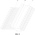
- the profiling connector 2 may be made of friction-resistant materials, such as polyetheretherketone.
- an elastic probe 21 that is commercially available is used as the probe in the jack of the profiling connector 2.
- the elastic probe 21 can be elastically deformed upon contact with the probe of the socket 7 and then maintain the state of elastic abutment, thereby converting the original sliding plugging between the probes into elastic abutment connection.
- the elastic probe 21 of the profiling connector 2 can be electrically connected with the detection equipment through connection wires, so as to send the voltage and temperature signals obtained through detection to the detection equipment.
- the first end of the operating portion 1 can be used for hand-holding, and a profiling connector 2 is provided at the second end of the operating portion 1, so as to avoid directly operating the connector with a small structure by hand.
- the profiling connector 2 can be inserted into the socket 7 to be detected and plugged by holding the operating portion 1 with hand, so that the staff can conveniently apply force to plug the profiling connector 2 in the socket 7, and the force application at this time is done by the whole hand instead of fingers acting on the connector, which solves the problem of injury to fingers of the staff effectively.
- an elastic probe 21 is provided in the jack of the profiling connector 2, and after the profiling connector 2 is inserted into the socket 7 to be detected and tested, the elastic probe 21 elastically abuts against the probe of the socket 7, thus changing the original sliding friction between the probe of the connector and the probe of the socket 7 into elastic abutment, effectively avoiding damage to the profiling connector 2 caused by repeated plugging and unplugging, improving the service life and reducing the usage cost.
- the test tool with a profiling connector further includes two guide pillars 3 connected with the second end of the operating portion 1 respectively, and the two guide pillars 3 are respectively arranged on two sides of the profiling connector 2.
- the guide pillar 3 may be a cylinder, and the distance by which the guide pillar 3 protrudes from the end portion of the second end of the operating portion 1 is greater than the distance by which the profiling connector 2 protrudes from the end portion of the second end of the operating portion 1, so that when the staff plugs the profiling connector 2 in the socket 7 by holding the operating portion 1, as shown in Fig. 4 , the two guide pillars 3 are first plugged in the guide holes on the module frame 8 of the battery module (which may be the original process holes on the module frame 8), and then provide guidance for inserting the profiling connector 2 into the socket 7. It should be noted that there are preferably two guide pillars 3 that are distributed on two sides of the profiling connector 2 in order to achieve a good guiding effect.
- the guide pillars 3 when the tooling is operated to plug the profiling connector 2 in the socket 7, the guide pillars 3 are plugged in the guide jacks on the module frame 8 of the battery module first, so as to achieve guidance for inserting the profiling connector 2 into the socket 7, providing the effect of facilitating plugging.
- the operating portion 1 includes: a first operating body 11, a second operating body 12 and an elastic member 13; the first end of the first operating body 11 is used for hand-holding, and the second end is provided with the profiling connector 2; the first end of the second operating body 12 is used for hand-holding, and the second end is provided with a hook 1211, and the position of the second operating body 12 near the second end is hinged with the second end of the first operating body 11, and the hook 1211 is used to be clamped with the battery module when the profiling connector 2 is inserted into the socket 7; the elastic member 13 is arranged between the first operating body 11 and the second operating body 12 so that a preset included angle is formed between the first operating body 11 and the second operating body 12, and is used to provide resilience.
- the combination of the first operating body 11, the second operating body 12 and the elastic member 13 forms a gripping body structure capable of elastic resilience.
- the first end of the first operating body 11 may be provided as a ring-shaped structure, or a rod-shaped structure that is convenient to hand-hold, or a structure similar to other existing handle structures that are convenient to hand-hold.
- the connection between the second end and the profiling connector 2 may be connection through bolts or may be clamping connection.
- the clamping connection may include clamping the profiling connector 2 with a clamping ring provided at the second end of the first operating body 11, or by clamping of a clamping block provided on the profiling connector 2 to a clamping slot provided at the second end of the first operating body 11.
- the first end of the second operating body 12 may be provided to have the same structure as the first end of the first operating body 11, as long as it is convenient to hand-hold, and details thereof will not be repeated here.
- the hook 1211 at the second end of the second operating body 12 may be a hook 1211 in the form of a groove matching the hole in the module frame 8 of the battery module.
- the elastic member 13 may be any form of component that generates an elastic abutting force, such as an elastic plunger, a spring, a leaf spring, or the like, and the elastic member 13 can be arranged between the first operating body 11 and the second operating body 12 by conventional means.
- an elastic plunger such as an elastic plunger, a spring, a leaf spring, or the like
- the elastic member 13 can be arranged between the first operating body 11 and the second operating body 12 by conventional means.
- the operator when inserting the profiling connector 2 into the socket 7 in the embodiment of the present application, the operator can apply a gripping force to the first operating body 11 and the second operating body 12, so that the first operating body 11 and the second operating body 12 rotate and approach relative to each other. At this time, the hook 1211 at the second end of the second operating body 12 is relatively far away from the profiling connector 2.
- the staff plugs the profiling connector 2 in the socket 7 by holding the first operating portion 1, the staff can release the gripping force applied to the first operating body 11 and the second operating body 12, and the hook 1211 at the second end of the second operating body 12 is clamped with the module frame 8 of the battery module.
- the elastic force acts on the first operating body 11 and the second operating body 12 respectively, so that the profiling connector 2 at the second end of the first operating body 11 is inserted into the socket 7, with the hook 1211 of the second operating body 12 being clamped with the module frame 8, so that the first operating body 11 and the second operating body 12 are in a state of gripping the module frame 8, and then the test tool with the profiling connector and the battery module are in a state of relatively stable connection, thereby ensuring stable connection between the profiling connector 2 and the socket 7.
- a hinge block 14 is connected with a first side face of the first operating body 11, the first end of the hinge block 14 is aligned with the second end of the first operating body 11 and is provided with a first hinge ring 141, and the second operating body 12 is provided with a second hinge ring 1212, the first hinge ring 141 and the second hinge ring 1212 being hinged via a rotating shaft 15.
- the arrangement of the hinge block 14 can simplify the structure of the first operating body 11.
- the first operating body 11 can be provided in a plate shape as a whole, and then the hinge block 14 is connected with the first side face of the operating body 11 through bolt connection.
- the second hinge ring 1212 is provided on the second operating body 12, hinging of the first operating body 11 with the second operating body 12 can be realized conveniently and quickly.
- the second operating body 12 includes two connecting legs 121, the second hinge rings 1212 are respectively arranged on the two connecting legs 121, and the hooks 1211 are arranged at the first ends of the connecting legs 121.
- the two second hinge rings 1212 are respectively hinged with the first hinge rings 141 of the two hinge blocks 14.
- the second operating body 12 further includes a crossbar 122, and two ends of the crossbar are respectively connected with the second ends of the two connecting legs to form a structure for hand-holding.
- the second operating body 12 is provided in a frame shape formed of a crossbar 122 and two connecting legs 121, so that the crossbar 122 is convenient for the staff to hand-hold, and the first ends of the two connecting legs 121 are convenient for providing the hook 1211, while the two separate connecting legs 121 facilitate the clamping connection between the hook 1211 and the module frame 8.
- the second operating body 12 in the form of connecting legs 121 can reduce weight and facilitate operation.
- a suitable distance is kept between the two connecting legs 121, so that the two connecting legs 121 can be arranged directly facing the two guide pillars 3.
- the profiling connector 2 is inserted into the socket 7, and the hook 1211 of the connecting leg 121 is clamped with the module frame 8, under the action of the elastic member 13, the first operating body 11 and the second operating body 12 are in a state of gripping the module frame 8, and then the test tool with the profiling connector and the battery module are in a state of relatively stable connection, thereby ensuring stable connection between the profiling connector 2 and the socket 7.
- the test tool with a profiling connector further includes:
- the first ends of the two abutting blocks 4 are respectively connected with the second end of the first operating body 11, and the second ends thereof extend in a direction toward the connecting legs 121 and abut against the connecting legs 121.
- the two guide pillars 3 are respectively connected with the two abutting blocks 4.
- the two abutting blocks 4 can be connected with the second end of the first operating body 11 by bolts, and the two guide pillars 3 can be arranged in the preset connection holes or slots of the two abutting blocks 4 by way of interference fit.
- the two abutting blocks 4 can protect the guide pillars 3 to prevent the connecting legs 121 of the second operating body 12 from abutting against the guide pillars 3 when the tooling is not operating, i.e., in the initial state, which causes deformation of the guide pillars 3 and affects the guiding accuracy.
- the test tool with a profiling connector further includes: a first fastener 5 that is connected with the first operating body 11, has an accommodating space 51 in the middle, and has a plurality of jacks 52 communicating with the accommodating space 51 at its first end.
- the profiling connector 2 is connected with the first end of the first fastener 5, and the elastic probe 21 extends into the accommodating space 51 through the jack 52.
- the first operating body 11 may be in the shape of a plate as a whole, and the first fastener 5 may also be in the shape of a plate as a whole, so as to facilitating connection of the two.
- the connection between the two may be connection through bolts.
- the accommodating space 51 provided on the first fastener 5 may be a groove provided on a side face of the first fastening body of the plate body structure, or a hollow that runs through both side faces.
- the distribution pattern of the plurality of jacks 52 provided at the first end of the first fastener 5 needs to match with the distribution pattern of the jacks of the profiling connector 2.
- the arrangement of the first fastener 5 facilitates connection of the profiling connector 2 with the first operating body 11, while the accommodating space 51 is provided in the first fastener 5, which can facilitate connection of the elastic probe 21 of the profiling connector 2 with the wire of the testing equipment.
- the test tool with a profiling connector further includes: a second fastener 6 connected with the first fastener 5.
- the first end of the first fastener 5 is inserted to and mated with the tail end of the profiling connector 2
- a first clamping portion 22 is provided on one side of the profiling connector 2
- a second clamping portion 61 is provided on the second fastener 6, and the first clamping portion 22 is clamped with the second clamping portion 61.
- the second fastener 6 can be adapted to the first fastener 5, that is, when the first fastener 5 is in the shape of a plate as a whole, the second fastener 6 may also be provided in a plate shape and then be connected with the first fastener 5 by bolt fixing.
- the second fastener 6 is provided to fasten the profiling connector 2 to the first fastener 5 by clamping, which is convenient for subsequent disassembly and maintenance.
- steps 54 are provided on opposite sides of the first end of the first fastener 5, and a groove 23 is provided at the tail end of the profiling connector 2, and the groove 23 is mated with the steps 54.
- a stepped block protruding from one side of the tail end of the profiling connector 2 forms a first clamping portion 22, and the second clamping portion 61 is a clamping slot on the second fastener 6.
- connection between the profiling connector 2 and the first fastener 5 is simple and convenient, and the clamping between the profiling connector 2 and the second fastener 6 is convenient and fast, and the clamping structure is simple and easy to form, enabling desirable stability after connection.
- the embodiment of the present application provides a battery testing method using the above-mentioned test tool with a profiling connector.
- the battery testing method specifically includes:
- the first end of the operating portion 1 can be used for hand-holding, and a profiling connector 2 is provided at the second end of the operating portion 1, so as to avoid directly operating the connector with a small structure by hand.
- the profiling connector 2 can be inserted into the socket 7 to be detected and plugged by holding the operating portion 1 with hand, so that the staff can conveniently apply force to plug the profiling connector 2 in the socket 7, and the force application at this time is done by the whole hand instead of fingers acting on the connector, which solves the problem of injury to fingers of the staff effectively.
- an elastic probe 21 is provided in the jack of the profiling connector 2, and after the profiling connector 2 is inserted into the socket 7 to be detected and plugged, the elastic probe 21 elastically abuts against the probe of the socket 7, thus changing the original sliding friction between the probe of the connector and the probe of the socket 7 into elastic abutment, effectively avoiding damage to the profiling connector 2 caused by repeated plugging and unplugging, improving the service life and reducing the usage cost.
Landscapes
- Physics & Mathematics (AREA)
- General Physics & Mathematics (AREA)
- Engineering & Computer Science (AREA)
- Manufacturing & Machinery (AREA)
- Chemical & Material Sciences (AREA)
- Chemical Kinetics & Catalysis (AREA)
- Electrochemistry (AREA)
- General Chemical & Material Sciences (AREA)
- Measuring Leads Or Probes (AREA)
- Details Of Connecting Devices For Male And Female Coupling (AREA)
Description
- The present application refers to
Chinese patent application No. 202122495588.0 filed on October 15, 2021 - The present application relates to the technical field of battery testing, and in particular to a test tool with a profiling connector and a battery testing method.
- With the rapid development of electric vehicles, power batteries for powering electric vehicles have also been rapidly developed.
- In some cases, the battery pack of the power battery is provided with several battery modules. In order to ensure the safety of use, it is necessary to collect and monitor the voltage and temperature of the battery modules during use of the power battery. Therefore, when producing power batteries, it is necessary to test the working voltage and temperature of the battery module. However, the standard connectors used in the test are not suitable for frequent plugging and unplugging, and can easily be damaged. In addition, these connectors are difficult to plug and unplug during manual operation, and long-term operation will cause serious wear on the operator's fingers.
- Therefore, further solutions are needed for the above-mentioned technical problems.
- In view of the above problems, the invention provides a test tool with a profiling connector as defined by
claim 1 and a battery testing method as defined byclaim 12, which can solve the problems of easily damaged connectors and manual operational difficulties during testing of the working voltage and temperature of battery modules using standard connectors. - The present invention is: a test tool with a profiling connector, including:
- an operating portion, a first end of the operating portion being used for hand-holding; and
- a profiling connector adapted to a socket to be detected and plugged, where an elastic probe is provided in a jack of the profiling connector, and the profiling connector is arranged at the second end of the operating portion opposite to the first end;
- in which the profiling connector is adapted to be inserted into the socket by holding the operating portion with hand, with the elastic probe abutting against and electrically connected with a probe of the socket.
- The operating portion is adapted to be used for hand-holding, and a profiling connector is provided at the second end of the operating portion, and the profiling connector can be inserted into the socket to be detected and plugged by holding the operating portion with hand, which is convenient for the staff to operate; meanwhile, an elastic probe is provided in the jack of the profiling connector, and once the profiling connector is inserted into the socket to be detected and plugged, the elastic probe elastically abuts against the probe of the socket, thus changing the original sliding friction between the probe of the connector and the probe of the socket into elastic abutment, which effectively avoids damage to the profiling connector caused by repeated plugging and unplugging and improves the service life.
- In some embodiments, the test tool with a profiling connector further comprises:
two guide pillars respectively connected with the second end of the operating portion and respectively arranged on two sides of the profiling connector. - In the embodiment of the present application, by adding the guide pillars, when the test tool is operated to plug the profiling connector in the socket, the guide pillars are plugged in the guide jacks on the module frame of the battery module first, so as to enable guidance for inserting the profiling connector into the socket, thus providing the effect of facilitating plugging.
- The operating portion of the invention further comprises:
- a first operating body, a second operating body and an elastic member;
- where a first end of the first operating body is used for hand-holding, and a second end thereof is provided with the profiling connector;
- a first end of the second operating body is used for hand-holding, and a second end thereof is provided with a hook, where the position of the second operating body near the second end is hinged with the second end of the first operating body, the hook is used to be clamped with the battery module when the profiling connector is inserted into the socket; and
- the elastic member is arranged between the first operating body and the second operating body so that a preset included angle is formed between the first operating body and the second operating body and is used to provide resilience.
- For the operating portion of the embodiment of the present application, after the profiling connector is plugged in, the hook at the second end of the second operating body is clamped with the module frame of the battery module, and under the effect of the elastic member, elastic force acts on the first operating body and the second operating body respectively, so that the profiling connector at the second end of the first operating body is inserted into the socket, and the hook of the second operating body is clamped with the module frame, so that the first operating body and the second operating body are in a state of gripping the module frame, and then the test tool with the profiling connector and the battery module are in a state of relatively stable connection, thereby ensuring stable connection between the profiling connector and the socket.
- In some embodiments, a hinge block is connected with a first side face of the first operating body, the first end of the hinge block is aligned with the second end of the first operating body and is provided with a first hinge ring, and the second operating body is provided with a second hinge ring, the first hinge ring and the second hinge ring being hinged via a rotating shaft. In this way, through the arrangement of the hinge block, hinging of the first operating body and the second operating body can be facilitated.
- In some embodiments, two hinge blocks are provided and are arranged at an interval;
the second operating body includes two connecting legs, the two connecting legs are each provided with a second hinge ring, and the hook is arranged at a first end of the connecting leg;
In which the two second hinge rings are respectively hinged with the first hinge rings of the two hinge blocks. - The second operating body with the connecting legs facilitates the arrangement of the hook and clamping of the hook to the module frame, and the second operating body in the form of connecting legs can reduce weight and facilitate operation.
- In some embodiments, the second operating body further includes a crossbar, and two ends of the crossbar are respectively connected with the second ends of the two connecting legs to form a structure for hand-holding. The frame-shaped second operating body formed of the crossbar and the two connecting legs is easy to hold with hand.
- In some embodiments, the test tool with a profiling connector further includes:
two abutting blocks, where the first ends of the two abutting blocks are respectively connected with the second end of the first operating body, and the second ends thereof extend in a direction toward the connecting legs and abut against the connecting legs; in which the two guide pillars are respectively connected with the two abutting blocks. In such a design, the two abutting blocks can protect the guide pillars to prevent the connecting legs of the second operating body from abutting against the guide pillars when the tooling is not operating, i.e., in the initial state, which causes deformation of the guide pillars and affects the guiding accuracy. - In some embodiments, the elastic member is an elastic plunger, a spring or a leaf spring.
- In some embodiments, the test tool with a profiling connector further includes:
a first fastener that is connected with the first operating body, has an accommodating space in the middle, and has a plurality of jacks communicating with the accommodating space at its first end; - In which the profiling connector is connected with the first end of the first fastener, and the elastic probe extends into the accommodating space through the jack.
- Through the arrangement of the first fastener, it is easy to connect the profiling connector with the first operating body, meanwhile, an accommodating space is provided in the first fastener, which can facilitate connection of the elastic probe of the profiling connector to the wire of the testing equipment.
- In some embodiments, the first fastener is connected with a side face of the first operating body facing the second operating body, the first end of the first fastener is aligned with the second end of the first operating body, and a lead wire channel communicating with the accommodating space is provided at the second end of the first fastener opposite to the first end. By providing the lead wire channel at the second end of the first fastener, it is convenient to lead out the wire connected with the elastic probe.
- In some embodiments, the test tool with a profiling connector further includes:
- a second fastener connected with the first fastener;
- in which the first end of the first fastener is inserted to and mated with the tail end of the profiling connector, a first clamping portion is provided on one side of the profiling connector, a second clamping portion is provided on the second fastener, and the first clamping portion is clamped with the second clamping portion.
- The second fastener is provided to fasten the profiling connector to the first fastener by clamping, which facilitates subsequent disassembly and maintenance.
- In some embodiments, steps are provided on opposite sides of the first end of the first fastener, a groove is provided at the tail end of the profiling connector, and the groove is mated with the steps; and
a stepped block protruding from one side of the tail end of the profiling connector forms a first clamping portion, and the second clamping portion is a clamping slot on the second fastener. - In such a design, the connection between the profiling connector and the first fastener is simple and convenient, and the clamping between the profiling connector and the second fastener is convenient and fast and the clamping structure is simple and easy to form, enabling desirable stability after connection.
- The invention of the present application further concerns : a battery testing method using the test tool with a profiling connector described above; the battery testing method specifically includes:
- providing a battery having a socket; and
- inserting the profiling connector into the socket by holding the operating portion with hand, with the elastic probe abutting against and electrically connected with a probe of the socket.
- In the technical solution of the embodiment of the present application, the first end of the operating portion can be used for hand-holding, and a profiling connector is provided at the second end of the operating portion, so as to avoid directly operating the connector with a small structure by hand. The profiling connector can be inserted into the socket to be detected and plugged by holding the operating portion with hand, so that the staff can conveniently apply force to plug the profiling connector in the socket, and the force application at this time is done by the whole hand instead of fingers acting on the connector, which solves the problem of injury to fingers of the staff effectively. Meanwhile, an elastic probe is provided in the jack of the profiling connector, and after the profiling connector is inserted into the socket to be detected and plugged, the elastic probe elastically abuts against the probe of the socket, thus changing the original sliding friction between the probe of the connector and the probe of the socket into elastic abutment, effectively avoiding damage to the profiling connector caused by repeated plugging and unplugging, improving the service life and reducing the usage cost.
- The description above is merely an overview of the technical solutions of embodiments the present application. In order to make the technical means of the embodiments of the present application more clearly understandable so that the technical means can be implemented according to the content of the specification and to make the above and other objectives, features and advantages of the embodiments of the present application more comprehensible, specific implementations of the present application are exemplified below.
- In order to illustrate the technical solutions of the embodiments of the present application more clearly, the drawings required in the embodiments of the present application shall be described briefly below. Obviously, the drawings described below are only some embodiments of the present application.
- Various other advantages and benefits will become apparent to those of ordinary skill in the art upon reading the following detailed description of the preferred implementations. The drawings are intended for the purpose of illustrating the preferred implementations only and shall not be considered as limitation to the present application. Also, the same components are denoted by the same reference numerals throughout the drawings. In the drawings:
-
Fig. 1 is a schematic structural view of a test tool with a profiling connector according to some embodiments of the present application viewed from a first perspective; -
Fig. 2 is a schematic structural view of a test tool with a profiling connector according to some embodiments of the present application viewed from a second perspective; -
Fig. 3 is a schematic exploded structural view of a test tool with a profiling connector according to some embodiments of the present application; -
Fig. 4 is a schematic structural view of the connection between the test tool with a profiling connector and the socket and the module frame according to some embodiments of the present application; -
Fig. 5 is a schematic structural view of the connection between the profiling connector and the first fastener and the second fastener according to some embodiments of the present application viewed from a first perspective; -
Fig. 6 is a schematic structural view of the connection between the profiling connector and the first fastener and the second fastener according to some embodiments of the present application viewed from a second perspective; -
Fig. 7 is a schematic structural view of a first fastener according to some embodiments of the present application viewed from a first perspective; -
Fig. 8 is a schematic structural view of a first fastener according to some embodiments of the present application viewed from a second perspective; -
Fig. 9 is a schematic structural view of a profiling connector according to some embodiments of the present application viewed from a first perspective; and -
Fig. 10 is a schematic structural view of a profiling connector according to some embodiments of the present application viewed from a second perspective. -
- operating
portion 1,first operating body 11,second operating body 12, connectingleg 121,hook 1211,second hinge ring 1212,crossbar 122,elastic member 13,hinge block 14,first hinge ring 141, rotatingshaft 15; -
profiling connector 2,elastic probe 21, first clampingportion 22,groove 23; - guide
pillar 3, abuttingblock 4; -
first fastener 5, accommodatingspace 51,jack 52,lead wire channel 53,step 54. -
second fastener 6,second clamping portion 61; -
socket 7;module frame 8. - Embodiments of the technical solutions of the present application will be described in detail below in conjunction with the drawings. The following embodiments are merely intended to illustrate the technical solutions of the present application more clearly, and therefore are only used as examples and shall not be used to limit the scope of protection of the present application.
- Unless otherwise defined, all technical and scientific terms used herein have the same meaning as commonly understood by those skilled in the art belonging to the technical field of the present application; the terms used herein are intended only for the purpose of describing specific embodiments and are not intended to limit the present application; the terms "including" and "having" and any variations thereof in the specification and the claims of the present application and in the brief description of the drawings above are intended to cover nonexclusive inclusion.
- In the description of the embodiments of the present application, the technical terms "first", "second", and the like are used only to distinguish between different objects, and shall not be understood as indicating or implying relative importance or implicitly specifying the number, particular order, or primary and secondary relation of the technical features indicated. In the description of the embodiments of the present application, unless otherwise explicitly and specifically defined, the phrase "a plurality of" means two or more.
- Reference herein to "an embodiment" means that a particular feature, structure, or characteristic described in connection with the embodiment can be included in at least one embodiment of the present application. The appearance of this phrase in various places in the specification does not necessarily refer to the same embodiment, nor does it refer to a separate or alternative embodiment that is mutually exclusive with other embodiments. It is explicitly and implicitly understood by those skilled in the art that the embodiments described herein may be combined with other embodiments.
- In the description of the embodiments of the present application, the term "and/or" is only an associative relationship for describing associated objects, indicating that there may be three relationships. For example, A and/or B may represent three cases: A alone, both A and B, and B alone. In addition, the character "/" herein generally means that the associated objects before and after it are in an "or" relationship.
- In the description of the embodiments of the present application, the term "a plurality of" refers to two or more (including two), and similarly, "multiple groups" refers to two or more (including two) groups, and "multiple sheets" refers to two or more (including two) sheets.
- In the description of the embodiments of the present application, the orientation or position relationship indicated by the technical terms "central", "longitudinal", "transverse", "length", "width", "thickness", "upper", "lower", "front", "back", "left", "right", "vertical", "horizontal", "top", "bottom", "inner", "outer", "clockwise", "counterclockwise", "axial", "radial", "circumferential", etc. are based on the orientation or position relationship shown in the drawings and are intended to facilitate the description of the embodiments of the present application and simplify the description only, rather than indicating or implying that the device or element referred to must have a particular orientation or be constructed and operated in a particular orientation, and therefore are not to be interpreted as limitations on the embodiments of the present application.
- In the description of the embodiments of the present application, unless otherwise expressly specified and defined, the technical terms "mount", "join", "connect", "fix", etc. should be understood in a broad sense, such as, a fixed connection, a detachable connection, or an integral connection; a mechanical connection, or an electrical connection; a direct connection, an indirect connection through an intermediate medium, an internal communication between two elements, or interaction between two elements. For those of ordinary skill in the art, the specific meanings of the above terms in the embodiments of the present application can be understood according to specific situations.
- At present, with the development of international and domestic markets, power batteries are increasingly used. The power batteries are used in energy storage power source systems such as hydraulic, thermal, wind and solar power stations as well as in electric vehicles such as electric bicycles, electric motorcycles and electric cars, and military equipment and aerospace fields. With the continuous expansion of the application field of the power batteries, the market demand is also constantly expanding.
- The inventor has noted that the power batteries should not only have good power storage and discharge functions, but also ensure safe operation during work, that is, it is necessary to ensure that the voltage and temperature of the battery module in the power batteries are within a safe range during operation. Therefore, a standard socket capable of collecting voltage and temperature is provided on the battery module, and the voltage and temperature of the battery module can be detected in real time by connection with the socket. To ensure the safety of the battery module during operation, it is necessary to detect the voltage and temperature of the battery module when it is working, that is, when charging and discharging, and to detect the effect of connection of the socket with the battery module before the power battery leaves the factory. In some cases, the detection of the voltage and temperature of the battery module before leaving the factory includes plugging a standard connector that matches the socket in the socket, then obtaining the voltage and temperature of the battery module during operation through the detection settings, and determining whether the socket is effectively connected with the battery module.
- As the plugging of the standard connector in the socket is very tight, usually with a fit tolerance of <±0.2mm, it is very difficult to plug and unplug manually, especially when testing mass-produced battery modules. Repeated plugging and unplugging will cause injury to the fingers of the operator; in addition, the probes in the standard connector and the socket are fitted to each other by sliding, and the service life of the connector generally includes 30 times of plugging, which is not suitable for testing of mass-produced battery modules, and will lead to frequent replacement of connectors, resulting in increased usage costs.
- In order to solve the above-mentioned problems, the inventor found through research that an easy-to-operate tooling can be designed to carry out the operation of plugging the above-mentioned connector in the socket, so as to solve the problem that existing connector plugging causes injury to the fingers of the staff; meanwhile, a profiling connector of a long service life can be provided in the tool. For example, the shell is made of wear-resistant materials, and an elastic probe is provided in the profiling connector to convert the sliding friction contact between the probe of the connector and the probe of the socket into elastic abutment contact, thereby solving the problem of increased usage costs due to insufficient service life of the connector.
- The test tool with a profiling connector disclosed in the embodiment of the present application is used in enterprises for mass-production of batteries as well as in enterprises for non-mass production of batteries, and also in enterprises that produce other electronic products, as long as it is used in a working environment involving repeated plugging and unplugging of a connector in and out of a socket for testing.
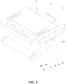
- As shown in
Figs. 1 to 3 , according to some embodiments of the present application, an embodiment of the present application provides a test tool with a profiling connector, including:
an operatingportion 1, a first end of the operatingportion 1 being used for hand-holding; aprofiling connector 2 adapted to asocket 7 to be detected and plugged, where anelastic probe 21 is provided in the jack of theprofiling connector 2, and theprofiling connector 2 is arranged at a second end of the operatingportion 1 opposite to the first end. Theprofiling connector 2 can be inserted into thesocket 7 by holding the operatingportion 1 with hand, with theelastic probe 21 abutting against and electrically connected with a probe of thesocket 7. - The operating
portion 1 is the portion for the staff to operate of the test tool with a profiling connector in the embodiment of the present application. The operatingportion 1 may be made of metal materials, such as stainless steel, aluminum alloy, magnesium alloy, etc., and may also be made of plastic materials meeting the use strength requirement. The holding structure at the first end of the operatingportion 1 may be provided with a ring-shaped handle, a rod-shaped handle, or the like, and the connection between the second end of the operatingportion 1 and theprofiling connector 2 may be made through bolt connection or through clamping with a clamping structure. - The
profiling connector 2 is so called because the shape and structure of theprofiling connector 2 can be adapted according to the structure of thesocket 7 to be detected and plugged, so as to meet the requirements of plugging and matching ofsockets 7 with various structures. Theprofiling connector 2 may be made of friction-resistant materials, such as polyetheretherketone. However, it should be noted that anelastic probe 21 that is commercially available is used as the probe in the jack of theprofiling connector 2. Theelastic probe 21 can be elastically deformed upon contact with the probe of thesocket 7 and then maintain the state of elastic abutment, thereby converting the original sliding plugging between the probes into elastic abutment connection. Theelastic probe 21 of theprofiling connector 2 can be electrically connected with the detection equipment through connection wires, so as to send the voltage and temperature signals obtained through detection to the detection equipment. - In the technical solution of the embodiment of the present application, the first end of the operating
portion 1 can be used for hand-holding, and aprofiling connector 2 is provided at the second end of the operatingportion 1, so as to avoid directly operating the connector with a small structure by hand. Theprofiling connector 2 can be inserted into thesocket 7 to be detected and plugged by holding the operatingportion 1 with hand, so that the staff can conveniently apply force to plug theprofiling connector 2 in thesocket 7, and the force application at this time is done by the whole hand instead of fingers acting on the connector, which solves the problem of injury to fingers of the staff effectively. Meanwhile, anelastic probe 21 is provided in the jack of theprofiling connector 2, and after theprofiling connector 2 is inserted into thesocket 7 to be detected and tested, theelastic probe 21 elastically abuts against the probe of thesocket 7, thus changing the original sliding friction between the probe of the connector and the probe of thesocket 7 into elastic abutment, effectively avoiding damage to theprofiling connector 2 caused by repeated plugging and unplugging, improving the service life and reducing the usage cost. - As shown in
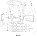
Figs. 1 to 3 , according to some embodiments of the present application, optionally, the test tool with a profiling connector further includes twoguide pillars 3 connected with the second end of the operatingportion 1 respectively, and the twoguide pillars 3 are respectively arranged on two sides of theprofiling connector 2. - Specifically, the
guide pillar 3 may be a cylinder, and the distance by which theguide pillar 3 protrudes from the end portion of the second end of the operatingportion 1 is greater than the distance by which theprofiling connector 2 protrudes from the end portion of the second end of the operatingportion 1, so that when the staff plugs theprofiling connector 2 in thesocket 7 by holding the operatingportion 1, as shown inFig. 4 , the twoguide pillars 3 are first plugged in the guide holes on themodule frame 8 of the battery module (which may be the original process holes on the module frame 8), and then provide guidance for inserting theprofiling connector 2 into thesocket 7. It should be noted that there are preferably twoguide pillars 3 that are distributed on two sides of theprofiling connector 2 in order to achieve a good guiding effect. - In this embodiment, by adding the
guide pillars 3, when the tooling is operated to plug theprofiling connector 2 in thesocket 7, theguide pillars 3 are plugged in the guide jacks on themodule frame 8 of the battery module first, so as to achieve guidance for inserting theprofiling connector 2 into thesocket 7, providing the effect of facilitating plugging. - As shown in
Figs. 1 to 3 , according to some embodiments of the present application, optionally, the operatingportion 1 includes: afirst operating body 11, asecond operating body 12 and anelastic member 13; the first end of thefirst operating body 11 is used for hand-holding, and the second end is provided with theprofiling connector 2; the first end of thesecond operating body 12 is used for hand-holding, and the second end is provided with ahook 1211, and the position of thesecond operating body 12 near the second end is hinged with the second end of thefirst operating body 11, and thehook 1211 is used to be clamped with the battery module when theprofiling connector 2 is inserted into thesocket 7; theelastic member 13 is arranged between thefirst operating body 11 and thesecond operating body 12 so that a preset included angle is formed between thefirst operating body 11 and thesecond operating body 12, and is used to provide resilience. - Specifically, the combination of the
first operating body 11, thesecond operating body 12 and theelastic member 13 forms a gripping body structure capable of elastic resilience. The first end of thefirst operating body 11 may be provided as a ring-shaped structure, or a rod-shaped structure that is convenient to hand-hold, or a structure similar to other existing handle structures that are convenient to hand-hold. The connection between the second end and theprofiling connector 2 may be connection through bolts or may be clamping connection. For example, the clamping connection may include clamping theprofiling connector 2 with a clamping ring provided at the second end of thefirst operating body 11, or by clamping of a clamping block provided on theprofiling connector 2 to a clamping slot provided at the second end of thefirst operating body 11. - The first end of the
second operating body 12 may be provided to have the same structure as the first end of thefirst operating body 11, as long as it is convenient to hand-hold, and details thereof will not be repeated here. Thehook 1211 at the second end of thesecond operating body 12 may be ahook 1211 in the form of a groove matching the hole in themodule frame 8 of the battery module. By hinging the position of thesecond operating body 12 near the second end with the second end of thefirst operating body 11, it is ensured that the two can rotate relative to each other, while as shown inFig. 4 , thehook 1211 at the second end of thesecond operating body 12 is clamped with the hole in themodule frame 8. - The
elastic member 13 may be any form of component that generates an elastic abutting force, such as an elastic plunger, a spring, a leaf spring, or the like, and theelastic member 13 can be arranged between thefirst operating body 11 and thesecond operating body 12 by conventional means. For these conventional means, reference may be made to existing techniques, so description thereof will not be repeated here. - As shown in
Fig. 4 , when inserting theprofiling connector 2 into thesocket 7 in the embodiment of the present application, the operator can apply a gripping force to thefirst operating body 11 and thesecond operating body 12, so that thefirst operating body 11 and thesecond operating body 12 rotate and approach relative to each other. At this time, thehook 1211 at the second end of thesecond operating body 12 is relatively far away from theprofiling connector 2. After the staff plugs theprofiling connector 2 in thesocket 7 by holding thefirst operating portion 1, the staff can release the gripping force applied to thefirst operating body 11 and thesecond operating body 12, and thehook 1211 at the second end of thesecond operating body 12 is clamped with themodule frame 8 of the battery module. Under the action of theelastic member 13, the elastic force acts on thefirst operating body 11 and thesecond operating body 12 respectively, so that theprofiling connector 2 at the second end of thefirst operating body 11 is inserted into thesocket 7, with thehook 1211 of thesecond operating body 12 being clamped with themodule frame 8, so that thefirst operating body 11 and thesecond operating body 12 are in a state of gripping themodule frame 8, and then the test tool with the profiling connector and the battery module are in a state of relatively stable connection, thereby ensuring stable connection between theprofiling connector 2 and thesocket 7. - As shown in
Figs. 1 to 3 , according to some embodiments of the present application, optionally, ahinge block 14 is connected with a first side face of thefirst operating body 11, the first end of thehinge block 14 is aligned with the second end of thefirst operating body 11 and is provided with afirst hinge ring 141, and thesecond operating body 12 is provided with asecond hinge ring 1212, thefirst hinge ring 141 and thesecond hinge ring 1212 being hinged via a rotatingshaft 15. - Specifically, the arrangement of the
hinge block 14 can simplify the structure of thefirst operating body 11. At this time, thefirst operating body 11 can be provided in a plate shape as a whole, and then thehinge block 14 is connected with the first side face of the operatingbody 11 through bolt connection. Meanwhile, after thesecond hinge ring 1212 is provided on thesecond operating body 12, hinging of thefirst operating body 11 with thesecond operating body 12 can be realized conveniently and quickly. - As shown in
Figs. 1 to 3 , according to some embodiments of the present application, optionally, there are two hinge blocks 14 arranged at an interval. Thesecond operating body 12 includes two connectinglegs 121, the second hinge rings 1212 are respectively arranged on the two connectinglegs 121, and thehooks 1211 are arranged at the first ends of the connectinglegs 121. The two second hinge rings 1212 are respectively hinged with the first hinge rings 141 of the two hinge blocks 14. Thesecond operating body 12 further includes acrossbar 122, and two ends of the crossbar are respectively connected with the second ends of the two connecting legs to form a structure for hand-holding. - Specifically, the
second operating body 12 is provided in a frame shape formed of acrossbar 122 and two connectinglegs 121, so that thecrossbar 122 is convenient for the staff to hand-hold, and the first ends of the two connectinglegs 121 are convenient for providing thehook 1211, while the two separate connectinglegs 121 facilitate the clamping connection between thehook 1211 and themodule frame 8. Thesecond operating body 12 in the form of connectinglegs 121 can reduce weight and facilitate operation. - It should be noted that, preferably, a suitable distance is kept between the two connecting
legs 121, so that the two connectinglegs 121 can be arranged directly facing the twoguide pillars 3. In this way, after theguide pillar 3 is inserted in the guide hole of themodule frame 8, theprofiling connector 2 is inserted into thesocket 7, and thehook 1211 of the connectingleg 121 is clamped with themodule frame 8, under the action of theelastic member 13, thefirst operating body 11 and thesecond operating body 12 are in a state of gripping themodule frame 8, and then the test tool with the profiling connector and the battery module are in a state of relatively stable connection, thereby ensuring stable connection between theprofiling connector 2 and thesocket 7. - As shown in
Figs. 1 to 3 , according to some embodiments of the present application, optionally, the test tool with a profiling connector further includes: - two abutting
blocks 4. The first ends of the two abuttingblocks 4 are respectively connected with the second end of thefirst operating body 11, and the second ends thereof extend in a direction toward the connectinglegs 121 and abut against the connectinglegs 121. The twoguide pillars 3 are respectively connected with the two abuttingblocks 4. The two abuttingblocks 4 can be connected with the second end of thefirst operating body 11 by bolts, and the twoguide pillars 3 can be arranged in the preset connection holes or slots of the two abuttingblocks 4 by way of interference fit. - In such a design, the two abutting
blocks 4 can protect theguide pillars 3 to prevent the connectinglegs 121 of thesecond operating body 12 from abutting against theguide pillars 3 when the tooling is not operating, i.e., in the initial state, which causes deformation of theguide pillars 3 and affects the guiding accuracy. - As shown in
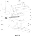
Figs. 3 and5 to 8 , according to some embodiments of the present application, optionally, the test tool with a profiling connector further includes:
afirst fastener 5 that is connected with thefirst operating body 11, has anaccommodating space 51 in the middle, and has a plurality ofjacks 52 communicating with theaccommodating space 51 at its first end. Theprofiling connector 2 is connected with the first end of thefirst fastener 5, and theelastic probe 21 extends into theaccommodating space 51 through thejack 52. - Specifically, the
first operating body 11 may be in the shape of a plate as a whole, and thefirst fastener 5 may also be in the shape of a plate as a whole, so as to facilitating connection of the two. The connection between the two may be connection through bolts. Theaccommodating space 51 provided on thefirst fastener 5 may be a groove provided on a side face of the first fastening body of the plate body structure, or a hollow that runs through both side faces. The distribution pattern of the plurality ofjacks 52 provided at the first end of thefirst fastener 5 needs to match with the distribution pattern of the jacks of theprofiling connector 2. - The arrangement of the
first fastener 5 facilitates connection of theprofiling connector 2 with thefirst operating body 11, while theaccommodating space 51 is provided in thefirst fastener 5, which can facilitate connection of theelastic probe 21 of theprofiling connector 2 with the wire of the testing equipment. - Further, the
first fastener 5 is connected with a side face of thefirst operating body 11 facing thesecond operating body 12, the first end of thefirst fastener 5 is aligned with the second end of thefirst operating body 11, and alead wire channel 53 communicating with theaccommodating space 51 is provided at the second end of thefirst fastener 5 opposite to the first end. - By arranging the
lead wire channel 53 at the second end of thefirst fastener 5, it is convenient to lead out the wire connected with theelastic probe 21. - As shown in
Figs. 3 ,5 ,6 ,9 and10 , according to some embodiments of the present application, optionally, the test tool with a profiling connector further includes:
asecond fastener 6 connected with thefirst fastener 5. The first end of thefirst fastener 5 is inserted to and mated with the tail end of theprofiling connector 2, afirst clamping portion 22 is provided on one side of theprofiling connector 2, asecond clamping portion 61 is provided on thesecond fastener 6, and thefirst clamping portion 22 is clamped with thesecond clamping portion 61. - Specifically, the
second fastener 6 can be adapted to thefirst fastener 5, that is, when thefirst fastener 5 is in the shape of a plate as a whole, thesecond fastener 6 may also be provided in a plate shape and then be connected with thefirst fastener 5 by bolt fixing. Thesecond fastener 6 is provided to fasten theprofiling connector 2 to thefirst fastener 5 by clamping, which is convenient for subsequent disassembly and maintenance. - Further, steps 54 are provided on opposite sides of the first end of the
first fastener 5, and agroove 23 is provided at the tail end of theprofiling connector 2, and thegroove 23 is mated with thesteps 54. A stepped block protruding from one side of the tail end of theprofiling connector 2 forms afirst clamping portion 22, and thesecond clamping portion 61 is a clamping slot on thesecond fastener 6. - In such a design, the connection between the
profiling connector 2 and thefirst fastener 5 is simple and convenient, and the clamping between theprofiling connector 2 and thesecond fastener 6 is convenient and fast, and the clamping structure is simple and easy to form, enabling desirable stability after connection. - According to some embodiments of the present application, the embodiment of the present application provides a battery testing method using the above-mentioned test tool with a profiling connector. The battery testing method specifically includes:
- providing a battery having a
socket 7; and - inserting the
profiling connector 2 into thesocket 7 by holding the operatingportion 1 with hand, with theelastic probe 21 abutting against and electrically connected with a probe of thesocket 7. - In the technical solution of the embodiment of the present application, the first end of the operating
portion 1 can be used for hand-holding, and aprofiling connector 2 is provided at the second end of the operatingportion 1, so as to avoid directly operating the connector with a small structure by hand. Theprofiling connector 2 can be inserted into thesocket 7 to be detected and plugged by holding the operatingportion 1 with hand, so that the staff can conveniently apply force to plug theprofiling connector 2 in thesocket 7, and the force application at this time is done by the whole hand instead of fingers acting on the connector, which solves the problem of injury to fingers of the staff effectively. Meanwhile, anelastic probe 21 is provided in the jack of theprofiling connector 2, and after theprofiling connector 2 is inserted into thesocket 7 to be detected and plugged, theelastic probe 21 elastically abuts against the probe of thesocket 7, thus changing the original sliding friction between the probe of the connector and the probe of thesocket 7 into elastic abutment, effectively avoiding damage to theprofiling connector 2 caused by repeated plugging and unplugging, improving the service life and reducing the usage cost. - Finally, it should be noted that the above embodiments are merely used for illustrating rather than limiting the technical solutions of the present application. The present application is not limited to the specific embodiments disclosed herein, but rather includes all technical solutions falling within the scope of the claims.
Claims (12)
- A test tool with a profiling connector (2), comprising:an operating portion (1), a first end of the operating portion (1) being used for hand-holding; anda profiling connector (2) adapted to a socket (7) to be detected and plugged, characterized in that an elastic probe (21) is arranged in a jack (52) of the profiling connector (2), and the profiling connector (2) is arranged at a second end of the operating portion (1) opposite to the first end;wherein the profiling connector (2) can be inserted into the socket (7) by holding the operating portion (1) with hand, and the elastic probe (21) abuts against and is electrically connected with a probe of the socket (7); whereinthe operating portion (1) comprises:a first operating body (11), a second operating body (12) and an elastic member;where a first end of the first operating body (11) is used for hand-holding, and a second end thereof is provided with the profiling connector (2);a first end of the second operating body (12) is used for hand-holding, and a second end thereof is provided with a hook (1211), where the position of the second operating body (12) near the second end is hinged with the second end of the first operating body (11), and the hook (1211) is used to be clamped with a battery module when the profiling connector (2) is inserted into the socket (7); andthe elastic member (13) is arranged between the first operating body (11) and the second operating body (12) so that a preset included angle is formed between the first operating body (11) and the second operating body (12), and is used to provide resilience.
- The test tool with a profiling connector (2) of claim 1, further comprising:
two guide pillars (3) respectively connected with the second end of the operating portion (1) and respectively arranged on two sides of the profiling connector (2). - The test tool with a profiling connector (2) of claim 1, wherein
a hinge block (14) is connected with a first side face of the first operating body (11), the first end of the hinge block (14) is aligned with the second end of the first operating body (11) and is provided with a first hinge ring (141), and the second operating body (12) is provided with a second hinge ring (1212), the first hinge ring (141) and the second hinge ring (1212) being hinged via a rotating shaft (15). - The test tool with a profiling connector (2) according to claim 3, whereintwo hinge blocks (14) are provided and are arranged at an interval;where the second operating body (12) comprises two connecting legs (121), the two connecting legs (121) are each provided with the second hinge ring (1212), and the hook (1211) is arranged at a first end of the connecting leg (121);wherein the two second hinge rings (1212) are respectively hinged with the first hinge rings (141) of the two hinge blocks (14).
- The test tool with a profiling connector (2) of claim 4, wherein
the second operating body (12) further comprises a crossbar (122), and two ends of the crossbar (122) are respectively connected with the second ends of the two connecting legs (121) to form a structure for hand-holding. - The test tool with a profiling connector (2) of claim 4 or 5, further comprising:two abutting blocks (4), where first ends of the two abutting blocks (4) are respectively connected with the second end of the first operating body (11), and second ends thereof extend toward the connecting legs (121) and abut against the connecting legs (121);wherein the two guide pillars (3) are respectively connected with the two abutting blocks (4).
- The test tool with a profiling connector (2) of any one of claims 1-4, wherein
the elastic member (13) is an elastic plunger, a spring or a leaf spring. - The test tool with a profiling connector (2) of claim 1, further comprising:a first fastener (5) that is connected with the first operating body (11), has an accommodating space (51) in the middle, and has a plurality of jacks (52) communicating with the accommodating space (51) at its first end;wherein the profiling connector (2) is connected with the first end of the first fastener (5), and the elastic probe (21) extends into the accommodating space (51) through the jack (52).
- The test tool with a profiling connector (2) of claim 8, wherein
the first fastener (5) is connected with a side face of the first operating body (11) facing the second operating body (12), the first end of the first fastener (5) is aligned with the second end of the first operating body (11), and a lead wire channel (53) communicating with the accommodating space (51) is provided at a second end of the first fastener (5) opposite to the first end. - The test tool with a profiling connector (2) of claim 8 or 9, further comprising:a second fastener (6) connected with the first fastener (5);where the first end of the first fastener (5) is inserted to and mated with a tail end of the profiling connector (2), a first clamping portion (22) is provided on one side of the profiling connector (2), and a second clamping portion (61) is provided on the second fastener (6), the first clamping portion (22) being clamped with the second clamping portion (61).
- The test tool with a profiling connector (2) of claim 10, whereinsteps (54) are provided on opposite sides of the first end of the first fastener (5), a groove (23) is provided at the tail end of the profiling connector (2), and the groove (23) is mated with the steps (54);a stepped block protruding from one side of the tail end of the profiling connector (2) forms the first clamping portion (22), and the second clamping portion (61) is a clamping slot on the second fastener (6).
- A battery testing method, wherein the test tool with a profiling connector (2) of any one of claims 1-11 is used; and the battery testing method specifically comprises:providing a battery having a socket (7); andinserting the profiling connector (2) into the socket (7) by holding the operating portion (1) with hand, and the elastic probe (21) abuts against and is electrically connected with a probe of the socket (7).
Applications Claiming Priority (2)
| Application Number | Priority Date | Filing Date | Title |
|---|---|---|---|
| CN202122495588.0U CN216213672U (en) | 2021-10-15 | 2021-10-15 | Test fixture with conformal connector |
| PCT/CN2022/124618 WO2023061362A1 (en) | 2021-10-15 | 2022-10-11 | Test tool having profiling connector and battery test method |
Publications (4)
| Publication Number | Publication Date |
|---|---|
| EP4325629A1 EP4325629A1 (en) | 2024-02-21 |
| EP4325629A4 EP4325629A4 (en) | 2024-09-18 |
| EP4325629B1 true EP4325629B1 (en) | 2025-06-04 |
| EP4325629C0 EP4325629C0 (en) | 2025-06-04 |
Family
ID=80883074
Family Applications (1)
| Application Number | Title | Priority Date | Filing Date |
|---|---|---|---|
| EP22880299.7A Active EP4325629B1 (en) | 2021-10-15 | 2022-10-11 | Test tool having profiling connector and battery test method |
Country Status (4)
| Country | Link |
|---|---|
| US (1) | US12517150B2 (en) |
| EP (1) | EP4325629B1 (en) |
| CN (1) | CN216213672U (en) |
| WO (1) | WO2023061362A1 (en) |
Families Citing this family (3)
| Publication number | Priority date | Publication date | Assignee | Title |
|---|---|---|---|---|
| CN216213672U (en) | 2021-10-15 | 2022-04-05 | 宁德时代新能源科技股份有限公司 | Test fixture with conformal connector |
| CN116718957B (en) * | 2023-08-07 | 2023-10-20 | 深圳市西点精工技术有限公司 | Automatic test equipment for high-speed connector |
| CN118011282B (en) * | 2024-03-25 | 2024-06-11 | 泰兴市航顺电子有限公司 | Rectangular connector connection testing device |
Family Cites Families (14)
| Publication number | Priority date | Publication date | Assignee | Title |
|---|---|---|---|---|
| US4360780A (en) * | 1981-10-30 | 1982-11-23 | Skutch Jr William G | Dual voltage battery tester |
| EP0508030B1 (en) * | 1991-04-10 | 1994-06-08 | George Edgar Callahan | Method and device for testing the charge-condition of car-batteries |
| US6254438B1 (en) * | 1999-10-21 | 2001-07-03 | Snap-On Tools Company | Battery side-terminal adapter and Kelvin connector |
| DE10024875B4 (en) * | 2000-05-16 | 2004-07-01 | Infineon Technologies Ag | Component holder system for use with test devices for testing electronic components |
| US6828796B2 (en) * | 2003-02-27 | 2004-12-07 | Lue Vang | Electrical continuity tester |
| US10222397B2 (en) * | 2014-09-26 | 2019-03-05 | Midtronics, Inc. | Cable connector for electronic battery tester |
| TWI599779B (en) * | 2016-07-11 | 2017-09-21 | 致茂電子股份有限公司 | Clipped probing device |
| CN206163779U (en) * | 2016-11-18 | 2017-05-10 | 深圳市得润电子股份有限公司 | Plug connector and socket connector |
| US11460504B2 (en) * | 2018-08-27 | 2022-10-04 | Chaojiong Zhang | Multi-chamber, explosion-proof, battery-testing apparatus |
| CN209387805U (en) * | 2018-12-27 | 2019-09-13 | 上海纪岩电力科技有限公司 | A kind of high-voltage cable joint resistance test equipment |
| CN112710960B (en) * | 2019-10-25 | 2024-04-26 | 上海沃尔沃汽车研发有限公司 | Integrated MSD connector test box for power battery test |
| CN212160026U (en) * | 2020-01-19 | 2020-12-15 | 赣州亿鹏能源科技有限公司 | Simple battery module detection card |
| CN213364819U (en) * | 2020-08-08 | 2021-06-04 | 武汉特尔斯特汽车技术科技有限公司 | New energy battery test pencil |
| CN216213672U (en) * | 2021-10-15 | 2022-04-05 | 宁德时代新能源科技股份有限公司 | Test fixture with conformal connector |
-
2021
- 2021-10-15 CN CN202122495588.0U patent/CN216213672U/en active Active
-
2022
- 2022-10-11 EP EP22880299.7A patent/EP4325629B1/en active Active
- 2022-10-11 WO PCT/CN2022/124618 patent/WO2023061362A1/en not_active Ceased
-
2023
- 2023-12-07 US US18/532,886 patent/US12517150B2/en active Active
Also Published As
| Publication number | Publication date |
|---|---|
| CN216213672U (en) | 2022-04-05 |
| EP4325629A4 (en) | 2024-09-18 |
| WO2023061362A1 (en) | 2023-04-20 |
| US20240103039A1 (en) | 2024-03-28 |
| US12517150B2 (en) | 2026-01-06 |
| EP4325629A1 (en) | 2024-02-21 |
| EP4325629C0 (en) | 2025-06-04 |
Similar Documents
| Publication | Publication Date | Title |
|---|---|---|
| EP4325629B1 (en) | Test tool having profiling connector and battery test method | |
| CN108054609A (en) | Testing terminal short-circuit device | |
| CN108557093B (en) | Quick reloading device of multi-rotor unmanned aerial vehicle inspection system | |
| CN219759883U (en) | Battery module, battery and electric equipment | |
| CN207541235U (en) | A kind of single battery and module-testing device | |
| CN220752170U (en) | Battery cell clamp | |
| CN110911595A (en) | Battery module data acquisition structure and battery module with same | |
| CN117458176B (en) | Power equipment wire clamp | |
| CN219086177U (en) | Lithium battery pole connection structure, battery module and battery pack | |
| EP4279927B1 (en) | Test clip and testing assembly | |
| CN218724911U (en) | Utmost point ear atress test fixture of electricity core utmost point ear bending, roll flat process | |
| CN113782283B (en) | Steel cap assembling and disassembling device and auxiliary assembly thereof | |
| CN201877624U (en) | Socket | |
| CN212063579U (en) | Equipment for balancing voltage between monomers in lithium battery pack | |
| CN202720246U (en) | Electric connector for testing | |
| CN219758316U (en) | Test fixture assembly and test equipment | |
| CN212848962U (en) | Electric connector | |
| CN223967440U (en) | Plug-in connecting wire convenient to connect | |
| CN219874182U (en) | Output port and assembled battery | |
| CN217639179U (en) | Quick connecting device for cable test | |
| CN221379606U (en) | Quick-change and mechanically-fixed general lithium battery | |
| CN219978379U (en) | An isolated electrical energy metering device meter frame | |
| CN220773188U (en) | A power distribution safety detection device | |
| CN214923936U (en) | Connector disassembling tool | |
| CN221631152U (en) | Bending test tooling, bending test equipment and battery production system |
Legal Events
| Date | Code | Title | Description |
|---|---|---|---|
| STAA | Information on the status of an ep patent application or granted ep patent |
Free format text: STATUS: THE INTERNATIONAL PUBLICATION HAS BEEN MADE |
|
| PUAI | Public reference made under article 153(3) epc to a published international application that has entered the european phase |
Free format text: ORIGINAL CODE: 0009012 |
|
| STAA | Information on the status of an ep patent application or granted ep patent |
Free format text: STATUS: REQUEST FOR EXAMINATION WAS MADE |
|
| 17P | Request for examination filed |
Effective date: 20231115 |
|
| AK | Designated contracting states |
Kind code of ref document: A1 Designated state(s): AL AT BE BG CH CY CZ DE DK EE ES FI FR GB GR HR HU IE IS IT LI LT LU LV MC ME MK MT NL NO PL PT RO RS SE SI SK SM TR |
|
| A4 | Supplementary search report drawn up and despatched |
Effective date: 20240820 |
|
| RIC1 | Information provided on ipc code assigned before grant |
Ipc: G01R 31/385 20190101ALI20240813BHEP Ipc: G01R 1/067 20060101ALI20240813BHEP Ipc: G01R 1/04 20060101ALI20240813BHEP Ipc: H01M 10/48 20060101AFI20240813BHEP |
|
| RAP1 | Party data changed (applicant data changed or rights of an application transferred) |
Owner name: CONTEMPORARY AMPEREX TECHNOLOGY(HONG KONG) LIMITED |
|
| DAV | Request for validation of the european patent (deleted) | ||
| DAX | Request for extension of the european patent (deleted) | ||
| GRAP | Despatch of communication of intention to grant a patent |
Free format text: ORIGINAL CODE: EPIDOSNIGR1 |
|
| STAA | Information on the status of an ep patent application or granted ep patent |
Free format text: STATUS: GRANT OF PATENT IS INTENDED |
|
| RIC1 | Information provided on ipc code assigned before grant |
Ipc: G01R 31/385 20190101ALI20250214BHEP Ipc: G01R 1/067 20060101ALI20250214BHEP Ipc: G01R 1/04 20060101ALI20250214BHEP Ipc: H01M 10/48 20060101AFI20250214BHEP |
|
| INTG | Intention to grant announced |
Effective date: 20250227 |
|
| GRAS | Grant fee paid |
Free format text: ORIGINAL CODE: EPIDOSNIGR3 |
|
| GRAA | (expected) grant |
Free format text: ORIGINAL CODE: 0009210 |
|
| STAA | Information on the status of an ep patent application or granted ep patent |
Free format text: STATUS: THE PATENT HAS BEEN GRANTED |
|
| AK | Designated contracting states |
Kind code of ref document: B1 Designated state(s): AL AT BE BG CH CY CZ DE DK EE ES FI FR GB GR HR HU IE IS IT LI LT LU LV MC ME MK MT NL NO PL PT RO RS SE SI SK SM TR |
|
| REG | Reference to a national code |
Ref country code: GB Ref legal event code: FG4D |
|
| REG | Reference to a national code |
Ref country code: CH Ref legal event code: EP |
|
| REG | Reference to a national code |
Ref country code: DE Ref legal event code: R096 Ref document number: 602022015668 Country of ref document: DE |
|
| REG | Reference to a national code |
Ref country code: IE Ref legal event code: FG4D |
|
| U01 | Request for unitary effect filed |
Effective date: 20250626 |
|
| U07 | Unitary effect registered |
Designated state(s): AT BE BG DE DK EE FI FR IT LT LU LV MT NL PT RO SE SI Effective date: 20250703 |
|
| PG25 | Lapsed in a contracting state [announced via postgrant information from national office to epo] |
Ref country code: ES Free format text: LAPSE BECAUSE OF FAILURE TO SUBMIT A TRANSLATION OF THE DESCRIPTION OR TO PAY THE FEE WITHIN THE PRESCRIBED TIME-LIMIT Effective date: 20250604 |
|
| PG25 | Lapsed in a contracting state [announced via postgrant information from national office to epo] |
Ref country code: GR Free format text: LAPSE BECAUSE OF FAILURE TO SUBMIT A TRANSLATION OF THE DESCRIPTION OR TO PAY THE FEE WITHIN THE PRESCRIBED TIME-LIMIT Effective date: 20250905 Ref country code: NO Free format text: LAPSE BECAUSE OF FAILURE TO SUBMIT A TRANSLATION OF THE DESCRIPTION OR TO PAY THE FEE WITHIN THE PRESCRIBED TIME-LIMIT Effective date: 20250904 |
|
| PG25 | Lapsed in a contracting state [announced via postgrant information from national office to epo] |
Ref country code: PL Free format text: LAPSE BECAUSE OF FAILURE TO SUBMIT A TRANSLATION OF THE DESCRIPTION OR TO PAY THE FEE WITHIN THE PRESCRIBED TIME-LIMIT Effective date: 20250604 |
|
| PG25 | Lapsed in a contracting state [announced via postgrant information from national office to epo] |
Ref country code: HR Free format text: LAPSE BECAUSE OF FAILURE TO SUBMIT A TRANSLATION OF THE DESCRIPTION OR TO PAY THE FEE WITHIN THE PRESCRIBED TIME-LIMIT Effective date: 20250604 |
|
| PG25 | Lapsed in a contracting state [announced via postgrant information from national office to epo] |
Ref country code: RS Free format text: LAPSE BECAUSE OF FAILURE TO SUBMIT A TRANSLATION OF THE DESCRIPTION OR TO PAY THE FEE WITHIN THE PRESCRIBED TIME-LIMIT Effective date: 20250904 |
|
| U20 | Renewal fee for the european patent with unitary effect paid |
Year of fee payment: 4 Effective date: 20251021 |
|
| PG25 | Lapsed in a contracting state [announced via postgrant information from national office to epo] |
Ref country code: IS Free format text: LAPSE BECAUSE OF FAILURE TO SUBMIT A TRANSLATION OF THE DESCRIPTION OR TO PAY THE FEE WITHIN THE PRESCRIBED TIME-LIMIT Effective date: 20251004 |
|
| PG25 | Lapsed in a contracting state [announced via postgrant information from national office to epo] |
Ref country code: SM Free format text: LAPSE BECAUSE OF FAILURE TO SUBMIT A TRANSLATION OF THE DESCRIPTION OR TO PAY THE FEE WITHIN THE PRESCRIBED TIME-LIMIT Effective date: 20250604 |
|
| PG25 | Lapsed in a contracting state [announced via postgrant information from national office to epo] |
Ref country code: CZ Free format text: LAPSE BECAUSE OF FAILURE TO SUBMIT A TRANSLATION OF THE DESCRIPTION OR TO PAY THE FEE WITHIN THE PRESCRIBED TIME-LIMIT Effective date: 20250604 |
|
| PG25 | Lapsed in a contracting state [announced via postgrant information from national office to epo] |
Ref country code: SK Free format text: LAPSE BECAUSE OF FAILURE TO SUBMIT A TRANSLATION OF THE DESCRIPTION OR TO PAY THE FEE WITHIN THE PRESCRIBED TIME-LIMIT Effective date: 20250604 |
|
| PLBE | No opposition filed within time limit |
Free format text: ORIGINAL CODE: 0009261 |
|
| STAA | Information on the status of an ep patent application or granted ep patent |
Free format text: STATUS: NO OPPOSITION FILED WITHIN TIME LIMIT |
|
| REG | Reference to a national code |
Ref country code: CH Ref legal event code: L10 Free format text: ST27 STATUS EVENT CODE: U-0-0-L10-L00 (AS PROVIDED BY THE NATIONAL OFFICE) Effective date: 20260416 |