EP4325459A1 - Light emitter driver circuit for smoke detector - Google Patents
Light emitter driver circuit for smoke detector Download PDFInfo
- Publication number
- EP4325459A1 EP4325459A1 EP23191786.5A EP23191786A EP4325459A1 EP 4325459 A1 EP4325459 A1 EP 4325459A1 EP 23191786 A EP23191786 A EP 23191786A EP 4325459 A1 EP4325459 A1 EP 4325459A1
- Authority
- EP
- European Patent Office
- Prior art keywords
- voltage
- resistor
- base
- transistor
- light emitter
- Prior art date
- Legal status (The legal status is an assumption and is not a legal conclusion. Google has not performed a legal analysis and makes no representation as to the accuracy of the status listed.)
- Granted
Links
Images


Classifications
-
- G—PHYSICS
- G08—SIGNALLING
- G08B—SIGNALLING SYSTEMS, e.g. PERSONAL CALLING SYSTEMS; ORDER TELEGRAPHS; ALARM SYSTEMS
- G08B17/00—Fire alarms; Alarms responsive to explosion
- G08B17/10—Actuation by presence of smoke or gases, e.g. automatic alarm devices for analysing flowing fluid materials by the use of optical means
- G08B17/103—Actuation by presence of smoke or gases, e.g. automatic alarm devices for analysing flowing fluid materials by the use of optical means using a light emitting and receiving device
- G08B17/107—Actuation by presence of smoke or gases, e.g. automatic alarm devices for analysing flowing fluid materials by the use of optical means using a light emitting and receiving device for detecting light-scattering due to smoke
-
- G—PHYSICS
- G08—SIGNALLING
- G08B—SIGNALLING SYSTEMS, e.g. PERSONAL CALLING SYSTEMS; ORDER TELEGRAPHS; ALARM SYSTEMS
- G08B17/00—Fire alarms; Alarms responsive to explosion
- G08B17/10—Actuation by presence of smoke or gases, e.g. automatic alarm devices for analysing flowing fluid materials by the use of optical means
- G08B17/103—Actuation by presence of smoke or gases, e.g. automatic alarm devices for analysing flowing fluid materials by the use of optical means using a light emitting and receiving device
-
- G—PHYSICS
- G08—SIGNALLING
- G08B—SIGNALLING SYSTEMS, e.g. PERSONAL CALLING SYSTEMS; ORDER TELEGRAPHS; ALARM SYSTEMS
- G08B29/00—Checking or monitoring of signalling or alarm systems; Prevention or correction of operating errors, e.g. preventing unauthorised operation
- G08B29/18—Prevention or correction of operating errors
- G08B29/20—Calibration, including self-calibrating arrangements
- G08B29/24—Self-calibration, e.g. compensating for environmental drift or ageing of components
-
- H—ELECTRICITY
- H05—ELECTRIC TECHNIQUES NOT OTHERWISE PROVIDED FOR
- H05B—ELECTRIC HEATING; ELECTRIC LIGHT SOURCES NOT OTHERWISE PROVIDED FOR; CIRCUIT ARRANGEMENTS FOR ELECTRIC LIGHT SOURCES, IN GENERAL
- H05B47/00—Circuit arrangements for operating light sources in general, i.e. where the type of light source is not relevant
- H05B47/10—Controlling the light source
- H05B47/105—Controlling the light source in response to determined parameters
- H05B47/14—Controlling the light source in response to determined parameters by determining electrical parameters of the light source
Definitions
- This invention relates to the field of smoke detectors, and more particularly, to a driver circuit for smoke detectors.
- Smoke detectors are generally subjected to wide temperature swings and are required to perform consistently and accurately without having any false alarms or going into a non-operative/trouble state.
- Photoelectric smoke detectors are widely used smoke detectors that typically include a driver circuit that is required to supply constant current to the light emitter of the smoke detector, regardless of the temperature around the smoke detector, such that the photon count or smoke count detected by the light receiver of the smoke detector does not vary with varying temperature.
- the driver circuits involve semiconductor devices that may generally be affected by varying temperatures. As a result, the driver circuits may fail to provide a constant current to the light emitter.
- the driver circuit may supply a higher current to the light emitter which may increase the photon count, leading to false alarm generation by the smoke detector.
- the driver circuit may supply less current to the light emitter which may decrease the photon count, thereby causing the smoke detector to go into a non-operative or troubled state.
- a driver circuit for a light emitter of a smoke detector comprises a transistor.
- the transistor comprises a base terminal, a collector terminal, and an emitter terminal.
- the collector terminal of the transistor is adapted to be operatively connected to the light emitter of the smoke detector.
- the driver further comprises a resistor of a predefined resistance configured to be connected to the emitter terminal of the transistor; and a controller operatively configured at the base terminal.
- the controller is configured to determine, at a manufacturing stage of the driver circuit, a first base voltage to be supplied to the base terminal of the transistor to enable the transistor to supply a predefined current to the light emitter, and further determine, at the manufacturing stage, a first resistor voltage across the resistor when the first base voltage is supplied to the base terminal.
- the controller is configured to set, before each smoke detection process, a value of the base voltage supplied to the base terminal to the first base voltage, determine a second resistor voltage across the resistor, compare the first resistor voltage with the second resistor voltage, determine a difference between the first resistor voltage and the second resistor voltage based on the comparison, and adjust the value of the base voltage supplied to the base terminal based on the determined difference to enable the transistor to supply the predefined current to the light emitter.
- the predefined current may correspond to a constant current to be supplied to the light emitter at a predefined temperature.
- the predefined temperature may be room temperature.
- the transistor may be a Darlington pair transistor or single transistor.
- the controller may be configured to determine a temperature at an area of interest (AOI) where the driver circuit or the smoke detector is installed based on one or more of the second resistor voltage across the resistor, the adjusted base voltage to be supplied to the base terminal to supply the predefined current to the light emitter, and the predefined resistance of the resistor.
- AOI area of interest
- the controller of the driver circuit may be a computing unit of the smoke detector, wherein the smoke detector comprises the light emitter and a light receiver.
- the controller of the driver circuit may be different from a computing unit of the smoke detector, and wherein the controller of the driver circuit is in communication with a computing unit of the smoke detector.
- the controller may comprise an analog to digital converter (ADC) to monitor voltage across the resistor; and a digital to analog converter (DAC) to supply an analog voltage to the base terminal of the transistor.
- ADC analog to digital converter
- DAC digital to analog converter
- the controller may comprise a processor, and a memory coupled to the processor and configured to store the values of the first voltage and the second voltage.
- a smoke detection and alarm device comprises a light emitter and a light receiver.
- the device further comprises a driver circuit comprising a transistor having a base terminal, a collector terminal, and an emitter terminal wherein the collector terminal of the transistor is operatively connected to the light emitter; a resistor of a predefined resistance configured to be connected to the emitter terminal of the transistor; and a controller operatively configured at the base terminal.
- the controller is configured to set, before an individual smoke detection process, a base voltage supplied to the base terminal to a predetermined base voltage value; determine a resistor voltage across the resistor; compare the determined resistor voltage to a predetermined resistor voltage value; and adjust the base voltage supplied to the base terminal based on the comparison.
- the predetermined base voltage value may be configured to enable the transistor to supply a constant current to the light emitter at room temperature, and the predetermined resistor voltage is the voltage across the resistor when the predetermined base voltage value is supplied to the base terminal.
- the light emitter and the light receiver may be enclosed within a hollow enclosure having a smoke chamber that is adapted to receive smoke therewithin.
- the controller may be configured to enable the transistor to supply the predefined current to the light emitter to enable the light emitter to emit photons within the smoke chamber to detect smoke within the smoke chamber based on a count of photons received by the light receiver upon getting reflected from particles of the smoke within the smoke chamber.
- the controller may be configured to generate alarm signals when the count of reflected photons within the smoke chamber exceeds a predefined value.
- the device may be adapted to be installed in one or more areas of interest (AOI) comprising one or more of an HVAC duct, room, hall, staircase, vehicle interior, and storage space.
- AOI areas of interest
- a method for supplying a constant current to a light emitter of a smoke detector includes the steps of connecting a collector terminal of a transistor to the light emitter of the smoke detector, a resistor of a predefined resistance to the emitter terminal of the transistor, and a controller at the base terminal. Further, at the manufacturing stage, the method includes a step determining, a first base voltage to be supplied to the base terminal of the transistor to enable the transistor to supply a predefined current to the light emitter, followed by another step of determining a first resistor voltage across the resistor when the first base voltage is supplied to the base terminal.
- the method includes the step of setting a value of the base voltage supplied to the base terminal to the first voltage, followed by the steps of determining a second resistor voltage across the resistor, comparing the first resistor voltage with the second voltage, and a difference between the first resistor voltage and the second resistor voltage based on the comparison. Accordingly, based on the determined difference, the method includes the step of adjusting the base voltage supplied to the base terminal to enable the transistor to supply the predefined current to the light emitter.
- the method may comprise the step of determining a temperature at an area of interest (AOI) where the driver circuit or the smoke detector is installed, based on one or more of the second resistor voltage across the resistor, the adjusted base voltage to be supplied to the base terminal to supply the predefined current to the light emitter, and the predefined resistance of the resistor.
- AOI area of interest
- the method may comprise the step of supplying the first base voltage to the base terminal of the transistor.
- the method may comprise the steps of computing, by the controller, a first compensation value that corresponds to the difference between the first resistor voltage and the second resistor voltage, divided by a first correction factor ranging from 0.1 to 16; adjusting, by the controller, the base voltage to be supplied to the base terminal to a value equal to a sum of the first base voltage and the first compensation value; and supplying, by the controller, the adjusted base voltage to the base terminal.
- the method may comprise the steps of computing, by the controller, a second compensation value that corresponds to the difference between the second resistor voltage and the first resistor voltage, divided by a second correction factor ranging from 0.1 to 16, adjusting the base voltage to be supplied to the base terminal to a value equal to a difference between the first base voltage and the second compensation value, and supplying, by the controller, the adjusted base voltage to the base terminal.
- the driver circuit 100 described herein may compensate for the effect of temperature on the driver circuit 100 and supplies a constant current to a light emitter 202 of the smoke detector 200, independent of the temperature around the smoke detector 200.
- the driver circuit 100 includes a transistor 102 having a base terminal (B), a collector terminal (C), and an emitter terminal (E).
- the transistor 102 acts like a switch for the light emitter 202, which can be a normal transistor or a Darlington pair transistor.
- the collector terminal of transistor 102 is adapted to be operatively connected to the light emitter 202 of the smoke detector.
- a resistor 106 of a predefined resistance (R) is connected to the emitter terminal of transistor 102.
- the resistor 106 limits the amount of current flowing through the light emitter 202.
- the driver circuit 100 includes a controller 104 operatively configured at the base terminal of the transistor 102.
- the light emitter current (I) depends on voltage drop (Vr) across the resistor 106, where the voltage drop (Vr) across the resistor 106 is equal to a difference in the base voltage (Vdac) supplied to the base terminal and the voltage drop (base-emitter voltage Vbe) across the transistor 102.
- Voltage drop across resistor 106 , Vr Vdac ⁇ Vbe
- Light emitter current , I Vr / R
- the light emitter current can be controlled to maintain a constant current value.
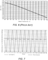
- a transistor involving semiconductors has a unique characteristic that its Vbe is highly dependent on temperature as shown in FIG. 6 .
- the Vbe decreases and vice versa.
- the existing smoke detectors upon variation of temperature, the light emitter current also varies, which leads to variation in photon counts in the existing smoke detectors. For instance, as already explained in the Background, at higher temperatures, the existing driver circuit may normally supply a higher current to the light emitter which may increase the photon count, thereby causing the smoke detector to mistakenly generate a false alarm.
- the existing driver circuit may normally supply a low current to the light emitter which may decrease the photon count, thereby causing the smoke detector to go into a non-operative or trouble state.
- This fluctuation in light emitter current is highly undesirable in smoke detectors.
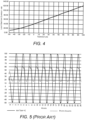
- the effect of temperature on the light emitter current in existing smoke detectors in 24 hours is shown in FIG. 4 , which also suggests that the current supplied to the light emitter varies with varying temperatures.
- the effect of temperature on light photon count in existing smoke detectors is shown in FIG. 5 , which suggests that the photon count emitted by the light emitter also varies with varying temperatures.
- this invention involves a temperature compensation technique without the requirement of any temperature sensors.
- This invention compensates for the effect of temperature on the smoke detector by configuring/programming the driver circuit 100 in such a way that the driver circuit 100 supplies a constant current to the light emitter 202 of the smoke detector 200, regardless of the temperature around the smoke detector 200 or driver circuit 100.
- controller 104 of the driver circuit monitors and stores the values of voltage (say a first base voltage) to be supplied to the base terminal of the transistor 102 to supply a constant current to the light emitter 202, and also monitors the voltage (say a first resistor voltage) across the resistor 106 when the first base voltage is supplied to the base terminal. Further, before each smoke detection process, controller 104 uses the data stored during the manufacturing stage and accordingly adjusts the base voltage to be supplied to the base terminal to enable transistor 102 to supply the constant current to the light emitter 202, regardless of the temperature around the smoke detector 200.
- the device 200 or smoke detector 200 includes the light emitter 202 and a light receiver 204 enclosed within a hollow enclosure/housing 206 having a smoke chamber 208 therewithin that is adapted to receive smoke from the area where the device 200 is installed.
- the light emitter 202 includes one or more of a LED, a laser light source, or an infra light source, and other known light emitting sources that are generally used as a light emitter in existing smoke detectors.
- the light receiver 204 is a photodiode or other light sensor that is generally used as light receiver 204s in existing smoke detectors.
- Device 200 further includes the driver circuit 100 of FIG. 1 , which includes the transistor 102 having a base terminal (B), a collector terminal (C), and an emitter terminal (E), where the collector terminal of the transistor 102 is operatively connected to the light emitter 202 of the device 200 and the resistor 106 of a predefined resistance is connected to the emitter terminal of the transistor 102.
- device 200 also includes the controller 104 operatively configured at the base terminal of the transistor 102, which includes an in-built or external ADC 114 to monitor the voltage across the resistor 106, and an in-built or external DAC 112 to supply an analog voltage to the base terminal of the transistor 102.
- controller 104 operatively configured at the base terminal of the transistor 102, which includes an in-built or external ADC 114 to monitor the voltage across the resistor 106, and an in-built or external DAC 112 to supply an analog voltage to the base terminal of the transistor 102.
- the device 200 is adapted to be installed in one or more areas of interest (AOIs) comprising one or more of an HVAC duct, room, hall, staircase, vehicle interior, and storage space, but not limited to the like.
- AOIs areas of interest
- the smoke detector/device 200 enables the transistor 102 to supply the predefined current to the light emitter 202 continuously, which enables the light emitter 202 to continuously emit a constant count of photons within the smoke chamber 208.
- AOIs areas of interest
- the light receiver 204 receives the reflected photon and enables the controller 104 to determine the count of light reflected by the particles of the smoke and correspondingly determine the amount of smoke in the AOI.
- device 200 includes one or more audio, and visual alarms such as LEDs, speakers, buzzers, and the like (collectively designated as 210, herein).
- the controller 104 is configured to generate alarm signals when the count of reflected photons or amount of smoke within the smoke chamber 208 exceeds a predefined value, which notifies or alerts occupants in the AOI about the smoke.
- the controller 104 being used in the driver circuit 100 of FIG. 1 as well as in device 200 of FIGs. 2A and B include a processor 108, and a memory 110 operatively coupled to the processor 108 storing instructions executable by the processor 108 to enable the controller 104 to do one or more operations such as smoke detection, temperature compensation, monitoring of voltages, current, and photon count, voltage supply, and alarm generation. Further, the values of the first base voltage and first resistor voltage collected during the manufacturing stage are also stored in the memory 110, which can be later used by controller 104 to compensate for the effect of temperature on the light emitter current. In some embodiments, the computing unit or controller 104 of the smoke detector/device 200 can be used as the controller 104 for the driver circuit 100.
- the common controller 104 can control the operation of the driver circuit 100 as well as the smoke detector/device 200. Further, in other embodiments, the controller 104 of the driver circuit 100 can be different from the computing unit of the smoke detector/device 200, however, the controller 104 of the driver circuit 100 remains operatively connected or in communication with the computing unit or controller 104 of the smoke detector/device 200 via known wired or wireless media.
- the controller 104 may include an in-built analog to digital converter (ADC) 114 to monitor the voltage across the resistor 106 and a digital to analog converter (DAC) 112 to supply an analog voltage to the base terminal of the transistor 102.
- ADC analog to digital converter
- DAC digital to analog converter
- the ADC 114 of the controller 104 remains operatively connected across the resistor 106.
- the DAC 112 of controller 104 remains operatively connected to the base terminal of transistor 102.
- the ADC 114 and DAC 112 can be external components that can be connected to a processor 108 associated with the controller 104, and all such embodiments are well within the scope of this invention.
- the ADC 114 may be replaced by a voltage sensor that can monitor the voltage across the resistor 106 and provide the monitored voltage data to the processor 108 of the controller 104.
- the DAC 112 may be replaced by a variable controlled voltage source that can supply analog voltage to the base terminal of the transistor 102, upon getting a command from the processor 108 of the controller 104, and all such embodiments are well within the scope of this invention.
- controller 104 may compensate for the effect of temperature on the smoke detector and maintain the supply of a constant predefined current to the light emitter 202 for a predefined temperature such as but not limited to room temperature, so that, regardless of temperature variation around the smoke detector varies, the same constant predefined current can be supplied to the light emitter 202.
- controller 104 monitors the voltage (first base voltage) to be supplied to the base terminal of transistor 102 to enable transistor 102 to supply the predefined current to the light emitter 202. Further, controller 104 determines a voltage (first resistor voltage) across the resistor 106 when the first base voltage is supplied to the base terminal. The determined values of the first base voltage and the first resistor voltage are permanently stored in the memory 110 associated with the controller 104. The above steps are automatically performed by the controller 104 just one time during the manufacturing stage.
- controller 104 sets a value of the base voltage to be supplied to the base terminal as the first base voltage and correspondingly determines a voltage (second resistor voltage) across the resistor 106. Further, controller 104 compares the first resistor voltage with the second resistor voltage and correspondingly determines a difference between the first resistor voltage and the second resistor voltage. Finally, controller 104 adjusts the voltage supplied to the base terminal based on the determined difference to enable transistor 102 to supply the predefined current to the light emitter 202.
- this invention is capable of compensating for the effect of temperature on the driver circuit 100 or smoke detector or device 200 and enables the supply of constant current (current required at room temperature) to the light emitter 202 of the smoke detector or device 200, regardless of the temperature around the smoke detector.
- controller 104 adjusts the DAC 112 to supply a base voltage (Vdac) equal to the same first base voltage to the base terminal of transistor 102.
- controller 104 computes a first compensation value ( ⁇ ) that corresponds to the difference between the first resistor voltage and the second resistor voltage, divided by a first correction factor (A) ranging from 0.1 to 16.
- ⁇ first resistor voltage ⁇ second resistor voltage / A
- controller 104 enables DAC 112 to adjust the base voltage to be supplied to the base terminal to a value equal to the sum of the first base voltage and the first compensation value ( ⁇ ).
- Adjusted base voltage Vdac First base voltage + ⁇ This adjusted base voltage (Vdac) is then supplied by the DAC 112 to the base terminal of transistor 102 to enable transistor 102 to supply the same constant predefined current to the light emitter 202, thereby maintaining a constant count of photons supplied by the light emitter 202 in the smoke detector, regardless of the lowering of temperature around the smoke detector than the predefined (room) temperature.
- controller 104 enables DAC 112 to adjust the base voltage to be supplied to the base terminal, to a value equal to a difference between the first base voltage and the second compensation value ( ⁇ ).
- Adjusted base voltage Vdac First voltage ⁇ ⁇
- This adjusted base voltage (Vdac) is then supplied by the DAC 112 of controller 104 to the base terminal of transistor 102 to enable transistor 102 to supply the same constant predefined current to the light emitter 202, thereby maintaining a constant count of photons supplied by the light emitter 202 in the smoke detector, regardless of the increase in temperature around the smoke detector than the room temperature.
- the effect of temperature on light photon count in the smoke detector or device 200 is illustrated.
- the light emitter 202 provides a constant count of the photons in the device 200 throughout 24 hours of the day, regardless of the temperature around the smoke detector or device 200, unlike the existing smoke detector which generates a fluctuating count of photon due to variation of the temperature.
- Method 300 includes step 302 of connecting an emitter terminal of a transistor to the light emitter of the smoke detector, a resistor of a predefined resistance to the collector terminal of the transistor, and a controller at the base terminal. Further, at the manufacturing stage, method 300 includes step 304 of determining a voltage (first base voltage) to be supplied to the base terminal of the transistor to enable the transistor to supply a predefined current to the light emitter, followed by another step 306 of determining a voltage (first resistor voltage) across the resistor when the first base voltage is supplied to the base terminal.
- method 300 includes step 308 of setting a value of the base voltage to be supplied to the base terminal to the first voltage, followed by step 310 of determining a voltage (second resistor voltage) across the resistor. Further, method 300 includes step 312 of comparing the first resistor voltage with the second resistor voltage and determining a difference between the first resistor voltage with the second resistor voltage. Accordingly, based on the determined difference, method 300 includes step 314 of adjusting the value of the base voltage to be supplied to the base terminal based on the determined difference to enable the transistor to supply the predefined current to the light emitter.
- method 300 comprises the step of supplying the first base voltage to the base terminal of the transistor. Further, in another example, when the difference between the first resistor voltage and the second resistor voltage is positive, method 300 includes the step of computing, by the controller, a first compensation value that corresponds to the difference between the first resistor voltage and the second resistor voltage, divided by a first correction factor (A) ranging from 0.1 to 16, followed by another step of adjusting the base voltage to be supplied to the base terminal to a value equal to a sum of the first base voltage and the first compensation value (A), and supplying the adjusted voltage to the base terminal.
- A first correction factor
- method 300 when the difference between the first resistor voltage and the second resistor voltage is negative, includes the step of computing, by the controller, a second compensation value that corresponds to the difference between the second resistor voltage and the first resistor voltage, divided by a second correction factor (B) ranging from 0.1 to 16, followed by another step of adjusting the base voltage to be supplied to the base terminal to a value equal to a difference between the first base voltage and the second compensation value (B), and supplying the adjusted voltage to the base terminal.
- B second correction factor
- this invention overcomes the drawback, shortcomings, and limitations associated with existing smoke detectors by compensating for the effect of temperature on the driver circuit and enabling the driver circuit to supply constant current to the light emitter or constant count of the photons in the smoke detector, regardless of the temperature around the smoke detector.
Landscapes
- Physics & Mathematics (AREA)
- General Physics & Mathematics (AREA)
- Chemical & Material Sciences (AREA)
- Analytical Chemistry (AREA)
- Business, Economics & Management (AREA)
- Emergency Management (AREA)
- Engineering & Computer Science (AREA)
- Computer Security & Cryptography (AREA)
- Fire-Detection Mechanisms (AREA)
Abstract
Description
- This patent application claims the benefit of priority of
US Provisional Patent Application No. 63/371,659, filed on Aug 17, 2022 - This invention relates to the field of smoke detectors, and more particularly, to a driver circuit for smoke detectors.
- Smoke detectors are generally subjected to wide temperature swings and are required to perform consistently and accurately without having any false alarms or going into a non-operative/trouble state. Photoelectric smoke detectors are widely used smoke detectors that typically include a driver circuit that is required to supply constant current to the light emitter of the smoke detector, regardless of the temperature around the smoke detector, such that the photon count or smoke count detected by the light receiver of the smoke detector does not vary with varying temperature. However, the driver circuits involve semiconductor devices that may generally be affected by varying temperatures. As a result, the driver circuits may fail to provide a constant current to the light emitter. For instance, at higher temperatures, the driver circuit may supply a higher current to the light emitter which may increase the photon count, leading to false alarm generation by the smoke detector. Similarly, at lower temperatures, the driver circuit may supply less current to the light emitter which may decrease the photon count, thereby causing the smoke detector to go into a non-operative or troubled state.
- There is, therefore, a need to compensate for the effect of temperature on the driver circuit and enable the driver circuit to supply constant current to the light emitter of the smoke detector, independent of the temperature around the smoke detector.
- According to a first aspect of the invention, a driver circuit for a light emitter of a smoke detector is provided. The driver circuit comprises a transistor. The transistor comprises a base terminal, a collector terminal, and an emitter terminal. The collector terminal of the transistor is adapted to be operatively connected to the light emitter of the smoke detector. The driver further comprises a resistor of a predefined resistance configured to be connected to the emitter terminal of the transistor; and a controller operatively configured at the base terminal. The controller is configured to determine, at a manufacturing stage of the driver circuit, a first base voltage to be supplied to the base terminal of the transistor to enable the transistor to supply a predefined current to the light emitter, and further determine, at the manufacturing stage, a first resistor voltage across the resistor when the first base voltage is supplied to the base terminal. The controller is configured to set, before each smoke detection process, a value of the base voltage supplied to the base terminal to the first base voltage, determine a second resistor voltage across the resistor, compare the first resistor voltage with the second resistor voltage, determine a difference between the first resistor voltage and the second resistor voltage based on the comparison, and adjust the value of the base voltage supplied to the base terminal based on the determined difference to enable the transistor to supply the predefined current to the light emitter.
- The predefined current may correspond to a constant current to be supplied to the light emitter at a predefined temperature.
- The predefined temperature may be room temperature.
- The transistor may be a Darlington pair transistor or single transistor.
- The controller may be configured to determine a temperature at an area of interest (AOI) where the driver circuit or the smoke detector is installed based on one or more of the second resistor voltage across the resistor, the adjusted base voltage to be supplied to the base terminal to supply the predefined current to the light emitter, and the predefined resistance of the resistor.
- The controller of the driver circuit may be a computing unit of the smoke detector, wherein the smoke detector comprises the light emitter and a light receiver.
- The controller of the driver circuit may be different from a computing unit of the smoke detector, and wherein the controller of the driver circuit is in communication with a computing unit of the smoke detector.
- The controller may comprise an analog to digital converter (ADC) to monitor voltage across the resistor; and a digital to analog converter (DAC) to supply an analog voltage to the base terminal of the transistor.
- The controller may comprise a processor, and a memory coupled to the processor and configured to store the values of the first voltage and the second voltage.
- According to a second aspect of the invention, a smoke detection and alarm device is provided. The device comprises a light emitter and a light receiver. The device further comprises a driver circuit comprising a transistor having a base terminal, a collector terminal, and an emitter terminal wherein the collector terminal of the transistor is operatively connected to the light emitter; a resistor of a predefined resistance configured to be connected to the emitter terminal of the transistor; and a controller operatively configured at the base terminal. The controller is configured to set, before an individual smoke detection process, a base voltage supplied to the base terminal to a predetermined base voltage value; determine a resistor voltage across the resistor; compare the determined resistor voltage to a predetermined resistor voltage value; and adjust the base voltage supplied to the base terminal based on the comparison.
- The predetermined base voltage value may be configured to enable the transistor to supply a constant current to the light emitter at room temperature, and the predetermined resistor voltage is the voltage across the resistor when the predetermined base voltage value is supplied to the base terminal.
- The light emitter and the light receiver may be enclosed within a hollow enclosure having a smoke chamber that is adapted to receive smoke therewithin.
- The controller may be configured to enable the transistor to supply the predefined current to the light emitter to enable the light emitter to emit photons within the smoke chamber to detect smoke within the smoke chamber based on a count of photons received by the light receiver upon getting reflected from particles of the smoke within the smoke chamber.
- The controller may be configured to generate alarm signals when the count of reflected photons within the smoke chamber exceeds a predefined value.
- The device may be adapted to be installed in one or more areas of interest (AOI) comprising one or more of an HVAC duct, room, hall, staircase, vehicle interior, and storage space.
- According to a third aspect of the invention, a method for supplying a constant current to a light emitter of a smoke detector is provided. The method includes the steps of connecting a collector terminal of a transistor to the light emitter of the smoke detector, a resistor of a predefined resistance to the emitter terminal of the transistor, and a controller at the base terminal. Further, at the manufacturing stage, the method includes a step determining, a first base voltage to be supplied to the base terminal of the transistor to enable the transistor to supply a predefined current to the light emitter, followed by another step of determining a first resistor voltage across the resistor when the first base voltage is supplied to the base terminal. Further, before each smoke detection process, the method includes the step of setting a value of the base voltage supplied to the base terminal to the first voltage, followed by the steps of determining a second resistor voltage across the resistor, comparing the first resistor voltage with the second voltage, and a difference between the first resistor voltage and the second resistor voltage based on the comparison. Accordingly, based on the determined difference, the method includes the step of adjusting the base voltage supplied to the base terminal to enable the transistor to supply the predefined current to the light emitter.
- The method may comprise the step of determining a temperature at an area of interest (AOI) where the driver circuit or the smoke detector is installed, based on one or more of the second resistor voltage across the resistor, the adjusted base voltage to be supplied to the base terminal to supply the predefined current to the light emitter, and the predefined resistance of the resistor.
- Where the difference between the first resistor voltage and the second resistor voltage is zero, the method may comprise the step of supplying the first base voltage to the base terminal of the transistor.
- Where the difference between the first resistor voltage and the second resistor voltage is positive, the method may comprise the steps of computing, by the controller, a first compensation value that corresponds to the difference between the first resistor voltage and the second resistor voltage, divided by a first correction factor ranging from 0.1 to 16; adjusting, by the controller, the base voltage to be supplied to the base terminal to a value equal to a sum of the first base voltage and the first compensation value; and supplying, by the controller, the adjusted base voltage to the base terminal.
- Where the difference between the first resistor voltage and the second resistor voltage is negative, the method may comprise the steps of computing, by the controller, a second compensation value that corresponds to the difference between the second resistor voltage and the first resistor voltage, divided by a second correction factor ranging from 0.1 to 16, adjusting the base voltage to be supplied to the base terminal to a value equal to a difference between the first base voltage and the second compensation value, and supplying, by the controller, the adjusted base voltage to the base terminal.
- The foregoing summary is illustrative only and is not intended to be in any way limiting. In addition to the illustrative aspects, embodiments, and features described above, further aspects, embodiments, features, and techniques of the invention will become more apparent from the following description taken in conjunction with the drawings.
- The accompanying drawings are included to provide a further understanding of this invention and are incorporated in and constitute a part of this specification. The drawings illustrate exemplary embodiments of the invention and, together with the description, serve to explain the principles of the invention.
- In the drawings, similar components and/or features may have the same reference label. Further, various components of the same type may be distinguished by following the reference label with a second label that distinguishes among the similar components. If only the first reference label is used in the specification, the description is applicable to any one of the similar components having the same first reference label irrespective of the second reference label.
-
FIG. 1 is a schematic diagram illustrating an exemplary the driver circuit. -
FIG. 2A is a schematic diagram illustrating an exemplary smoke detection and alarm device. -
FIG. 2B is a block diagram illustrating an exemplary the smoke detection and alarm device. -
FIG. 3 is a flow diagram illustrating an exemplary method for supplying a constant current to the light emitter of a smoke detector. -
FIG. 4 is a schematic diagram illustrating the effect of temperature on the light emitter current. -
FIG. 5 is a schematic diagram illustrating the effect of temperature on the light emitter current in existing smoke detectors in 24 hours. -
FIG. 6 is a schematic diagram illustrating the effect of temperature on the base-emitter voltage (Vbe) of transistor. -
FIG. 7 is a schematic diagram illustrating the effect of temperature on light photon count in the smoke detector or device of this invention. - The following is a detailed description of embodiments of the invention depicted in the accompanying drawings. The embodiments are in such detail as to clearly communicate the invention. However, the amount of detail offered is not intended to limit the anticipated variations of embodiments; on the contrary, the intention is to cover all modifications, equivalents, and alternatives falling within the scope of the appended claims.
- Various terms are used herein. To the extent a term used in a claim is not defined below, it should be given the broadest definition persons in the pertinent art have given that term as reflected in printed publications and issued patents at the time of filing.
- Referring to
FIG. 1 , an exemplary view of adriver circuit 100 for alight emitter 202 of asmoke detector 200 according to one or more embodiments. Thedriver circuit 100 described herein may compensate for the effect of temperature on thedriver circuit 100 and supplies a constant current to alight emitter 202 of thesmoke detector 200, independent of the temperature around thesmoke detector 200. Thedriver circuit 100 includes atransistor 102 having a base terminal (B), a collector terminal (C), and an emitter terminal (E). Thetransistor 102 acts like a switch for thelight emitter 202, which can be a normal transistor or a Darlington pair transistor. The collector terminal oftransistor 102 is adapted to be operatively connected to thelight emitter 202 of the smoke detector. Further, aresistor 106 of a predefined resistance (R) is connected to the emitter terminal oftransistor 102. Theresistor 106 limits the amount of current flowing through thelight emitter 202. Thedriver circuit 100 includes acontroller 104 operatively configured at the base terminal of thetransistor 102. - It should be obvious to a person skilled in the art that the light emitter current (I) depends on voltage drop (Vr) across the
resistor 106, where the voltage drop (Vr) across theresistor 106 is equal to a difference in the base voltage (Vdac) supplied to the base terminal and the voltage drop (base-emitter voltage Vbe) across thetransistor 102.

- Theoretically, by controlling Vdac, the light emitter current can be controlled to maintain a constant current value. However, practically, a transistor involving semiconductors has a unique characteristic that its Vbe is highly dependent on temperature as shown in
FIG. 6 . Thus, as temperature increases, the Vbe decreases and vice versa. As a result, in the existing smoke detectors, upon variation of temperature, the light emitter current also varies, which leads to variation in photon counts in the existing smoke detectors. For instance, as already explained in the Background, at higher temperatures, the existing driver circuit may normally supply a higher current to the light emitter which may increase the photon count, thereby causing the smoke detector to mistakenly generate a false alarm. Further, at lower temperatures, the existing driver circuit may normally supply a low current to the light emitter which may decrease the photon count, thereby causing the smoke detector to go into a non-operative or trouble state. This fluctuation in light emitter current is highly undesirable in smoke detectors. The effect of temperature on the light emitter current in existing smoke detectors in 24 hours is shown inFIG. 4 , which also suggests that the current supplied to the light emitter varies with varying temperatures. Further, the effect of temperature on light photon count in existing smoke detectors is shown inFIG. 5 , which suggests that the photon count emitted by the light emitter also varies with varying temperatures. - To overcome the above light emitter current fluctuation issue or photon count fluctuation issue due to varying temperatures in existing smoke detectors, this invention involves a temperature compensation technique without the requirement of any temperature sensors. This invention compensates for the effect of temperature on the smoke detector by configuring/programming the
driver circuit 100 in such a way that thedriver circuit 100 supplies a constant current to thelight emitter 202 of thesmoke detector 200, regardless of the temperature around thesmoke detector 200 ordriver circuit 100. - During the manufacturing stage,
controller 104 of the driver circuit monitors and stores the values of voltage (say a first base voltage) to be supplied to the base terminal of thetransistor 102 to supply a constant current to thelight emitter 202, and also monitors the voltage (say a first resistor voltage) across theresistor 106 when the first base voltage is supplied to the base terminal. Further, before each smoke detection process,controller 104 uses the data stored during the manufacturing stage and accordingly adjusts the base voltage to be supplied to the base terminal to enabletransistor 102 to supply the constant current to thelight emitter 202, regardless of the temperature around thesmoke detector 200. - Referring to
FIGs. 2A and 2B , exemplary views of representation of smoke detection and alarm device 200 (also referred to assmoke detector 200 ordevice 200, herein) employing thedriver circuit 100 ofFIG. 1 is illustrated. Thedevice 200 orsmoke detector 200 includes thelight emitter 202 and alight receiver 204 enclosed within a hollow enclosure/housing 206 having asmoke chamber 208 therewithin that is adapted to receive smoke from the area where thedevice 200 is installed. Thelight emitter 202 includes one or more of a LED, a laser light source, or an infra light source, and other known light emitting sources that are generally used as a light emitter in existing smoke detectors. Further, thelight receiver 204 is a photodiode or other light sensor that is generally used as light receiver 204s in existing smoke detectors.Device 200 further includes thedriver circuit 100 ofFIG. 1 , which includes thetransistor 102 having a base terminal (B), a collector terminal (C), and an emitter terminal (E), where the collector terminal of thetransistor 102 is operatively connected to thelight emitter 202 of thedevice 200 and theresistor 106 of a predefined resistance is connected to the emitter terminal of thetransistor 102. Further,device 200 also includes thecontroller 104 operatively configured at the base terminal of thetransistor 102, which includes an in-built orexternal ADC 114 to monitor the voltage across theresistor 106, and an in-built orexternal DAC 112 to supply an analog voltage to the base terminal of thetransistor 102. - The
device 200 is adapted to be installed in one or more areas of interest (AOIs) comprising one or more of an HVAC duct, room, hall, staircase, vehicle interior, and storage space, but not limited to the like. The smoke detector/device 200 enables thetransistor 102 to supply the predefined current to thelight emitter 202 continuously, which enables thelight emitter 202 to continuously emit a constant count of photons within thesmoke chamber 208. When smoke is present or generated in the AOI, a portion of the smoke enters thesmoke chamber 208 of thedevice 200. The particles of the smoke in thesmoke chamber 208 generally reflect the photon (emitted by the light emitter 202) towards thelight receiver 204. Further, thelight receiver 204 receives the reflected photon and enables thecontroller 104 to determine the count of light reflected by the particles of the smoke and correspondingly determine the amount of smoke in the AOI. In some embodiments,device 200 includes one or more audio, and visual alarms such as LEDs, speakers, buzzers, and the like (collectively designated as 210, herein). Thecontroller 104 is configured to generate alarm signals when the count of reflected photons or amount of smoke within thesmoke chamber 208 exceeds a predefined value, which notifies or alerts occupants in the AOI about the smoke. - The
controller 104 being used in thedriver circuit 100 ofFIG. 1 as well as indevice 200 ofFIGs. 2A and B include aprocessor 108, and amemory 110 operatively coupled to theprocessor 108 storing instructions executable by theprocessor 108 to enable thecontroller 104 to do one or more operations such as smoke detection, temperature compensation, monitoring of voltages, current, and photon count, voltage supply, and alarm generation. Further, the values of the first base voltage and first resistor voltage collected during the manufacturing stage are also stored in thememory 110, which can be later used bycontroller 104 to compensate for the effect of temperature on the light emitter current. In some embodiments, the computing unit orcontroller 104 of the smoke detector/device 200 can be used as thecontroller 104 for thedriver circuit 100. Thecommon controller 104 can control the operation of thedriver circuit 100 as well as the smoke detector/device 200. Further, in other embodiments, thecontroller 104 of thedriver circuit 100 can be different from the computing unit of the smoke detector/device 200, however, thecontroller 104 of thedriver circuit 100 remains operatively connected or in communication with the computing unit orcontroller 104 of the smoke detector/device 200 via known wired or wireless media. - The
controller 104, in some embodiments, may include an in-built analog to digital converter (ADC) 114 to monitor the voltage across theresistor 106 and a digital to analog converter (DAC) 112 to supply an analog voltage to the base terminal of thetransistor 102. TheADC 114 of thecontroller 104 remains operatively connected across theresistor 106. Further, theDAC 112 ofcontroller 104 remains operatively connected to the base terminal oftransistor 102. However, in some embodiments, theADC 114 andDAC 112 can be external components that can be connected to aprocessor 108 associated with thecontroller 104, and all such embodiments are well within the scope of this invention. In other embodiments, theADC 114 may be replaced by a voltage sensor that can monitor the voltage across theresistor 106 and provide the monitored voltage data to theprocessor 108 of thecontroller 104. Further, theDAC 112 may be replaced by a variable controlled voltage source that can supply analog voltage to the base terminal of thetransistor 102, upon getting a command from theprocessor 108 of thecontroller 104, and all such embodiments are well within the scope of this invention. - In some embodiments,
controller 104 may compensate for the effect of temperature on the smoke detector and maintain the supply of a constant predefined current to thelight emitter 202 for a predefined temperature such as but not limited to room temperature, so that, regardless of temperature variation around the smoke detector varies, the same constant predefined current can be supplied to thelight emitter 202. Initially, during the manufacturing stage,controller 104 monitors the voltage (first base voltage) to be supplied to the base terminal oftransistor 102 to enabletransistor 102 to supply the predefined current to thelight emitter 202. Further,controller 104 determines a voltage (first resistor voltage) across theresistor 106 when the first base voltage is supplied to the base terminal. The determined values of the first base voltage and the first resistor voltage are permanently stored in thememory 110 associated with thecontroller 104. The above steps are automatically performed by thecontroller 104 just one time during the manufacturing stage. - Later on, before each smoke detection process, the below temperature compensation steps are periodically and automatically performed by the
controller 104. Before each smoke detection process,controller 104 sets a value of the base voltage to be supplied to the base terminal as the first base voltage and correspondingly determines a voltage (second resistor voltage) across theresistor 106. Further,controller 104 compares the first resistor voltage with the second resistor voltage and correspondingly determines a difference between the first resistor voltage and the second resistor voltage. Finally,controller 104 adjusts the voltage supplied to the base terminal based on the determined difference to enabletransistor 102 to supply the predefined current to thelight emitter 202. Thus, this invention is capable of compensating for the effect of temperature on thedriver circuit 100 or smoke detector ordevice 200 and enables the supply of constant current (current required at room temperature) to thelight emitter 202 of the smoke detector ordevice 200, regardless of the temperature around the smoke detector. - In one example, when the real-time temperature around the smoke detector or
device 200 is equal to the predefined (room) temperature, the difference between the first resistor voltage and the second resistor voltage remains zero (i.e, the first resistor voltage and second resistor voltage remain equal), as a result, there is no requirement of adjustment of the light emitter current. In this case,controller 104 adjusts theDAC 112 to supply a base voltage (Vdac) equal to the same first base voltage to the base terminal oftransistor 102. - In another example, when the current temperature around the smoke detector or
device 200 is lower than the predefined (room) temperature, the difference between the first resistor voltage and the second resistor voltage becomes positive (i.e, the first resistor voltage is greater than the second resistor voltage). In such a case,controller 104 computes a first compensation value (α) that corresponds to the difference between the first resistor voltage and the second resistor voltage, divided by a first correction factor (A) ranging from 0.1 to 16.
controller 104 enablesDAC 112 to adjust the base voltage to be supplied to the base terminal to a value equal to the sum of the first base voltage and the first compensation value (α).
DAC 112 to the base terminal oftransistor 102 to enabletransistor 102 to supply the same constant predefined current to thelight emitter 202, thereby maintaining a constant count of photons supplied by thelight emitter 202 in the smoke detector, regardless of the lowering of temperature around the smoke detector than the predefined (room) temperature. - In yet another example, when the current temperature around the smoke detector or
device 200 is greater than the predefined (room) temperature, the difference between the first resistor voltage and the second resistor voltage is negative (i.e, the first resistor voltage is less than the second resistor voltage). In such a case,controller 104 computes a second compensation value (β) that corresponds to the difference between the second resistor voltage and the first resistor voltage, divided by a second correction factor (B) ranging from 0.1 to 16. β= (second resistor voltage - first resistor voltage)B - Further,
controller 104 enablesDAC 112 to adjust the base voltage to be supplied to the base terminal, to a value equal to a difference between the first base voltage and the second compensation value (β).
- This adjusted base voltage (Vdac) is then supplied by the
DAC 112 ofcontroller 104 to the base terminal oftransistor 102 to enabletransistor 102 to supply the same constant predefined current to thelight emitter 202, thereby maintaining a constant count of photons supplied by thelight emitter 202 in the smoke detector, regardless of the increase in temperature around the smoke detector than the room temperature. - Referring to
FIG. 7 , the effect of temperature on light photon count in the smoke detector ordevice 200 is illustrated. As can be inferred fromFIG. 6 and FIG. 7 , thelight emitter 202 provides a constant count of the photons in thedevice 200 throughout 24 hours of the day, regardless of the temperature around the smoke detector ordevice 200, unlike the existing smoke detector which generates a fluctuating count of photon due to variation of the temperature. - Referring to
FIG. 3 , exemplary steps involved inmethod 300 for supplying a constant current to the light emitter of a smoke detector/device, regardless of the temperature around the smoke detector are disclosed.Method 300 includesstep 302 of connecting an emitter terminal of a transistor to the light emitter of the smoke detector, a resistor of a predefined resistance to the collector terminal of the transistor, and a controller at the base terminal. Further, at the manufacturing stage,method 300 includesstep 304 of determining a voltage (first base voltage) to be supplied to the base terminal of the transistor to enable the transistor to supply a predefined current to the light emitter, followed by anotherstep 306 of determining a voltage (first resistor voltage) across the resistor when the first base voltage is supplied to the base terminal. Further, before each smoke detection process,method 300 includesstep 308 of setting a value of the base voltage to be supplied to the base terminal to the first voltage, followed bystep 310 of determining a voltage (second resistor voltage) across the resistor. Further,method 300 includesstep 312 of comparing the first resistor voltage with the second resistor voltage and determining a difference between the first resistor voltage with the second resistor voltage. Accordingly, based on the determined difference,method 300 includesstep 314 of adjusting the value of the base voltage to be supplied to the base terminal based on the determined difference to enable the transistor to supply the predefined current to the light emitter. - In one example, when the difference between the first resistor voltage and the second resistor voltage is zero,
method 300 comprises the step of supplying the first base voltage to the base terminal of the transistor. Further, in another example, when the difference between the first resistor voltage and the second resistor voltage is positive,method 300 includes the step of computing, by the controller, a first compensation value that corresponds to the difference between the first resistor voltage and the second resistor voltage, divided by a first correction factor (A) ranging from 0.1 to 16, followed by another step of adjusting the base voltage to be supplied to the base terminal to a value equal to a sum of the first base voltage and the first compensation value (A), and supplying the adjusted voltage to the base terminal. - Furthermore, in yet another example, when the difference between the first resistor voltage and the second resistor voltage is negative,
method 300 includes the step of computing, by the controller, a second compensation value that corresponds to the difference between the second resistor voltage and the first resistor voltage, divided by a second correction factor (B) ranging from 0.1 to 16, followed by another step of adjusting the base voltage to be supplied to the base terminal to a value equal to a difference between the first base voltage and the second compensation value (B), and supplying the adjusted voltage to the base terminal. - Thus, this invention overcomes the drawback, shortcomings, and limitations associated with existing smoke detectors by compensating for the effect of temperature on the driver circuit and enabling the driver circuit to supply constant current to the light emitter or constant count of the photons in the smoke detector, regardless of the temperature around the smoke detector.
- While the invention has been described with reference to exemplary embodiments, it will be understood by those skilled in the art that various changes may be made and equivalents may be substituted for elements thereof without departing from the scope of the invention as defined by the appended claims. Modifications may be made to adopt a particular situation or material to the teachings of the invention without departing from the scope thereof. Therefore, it is intended that the invention not be limited to the particular embodiment disclosed, but that the invention includes all embodiments falling within the scope of the invention as defined by the appended claims.
- In interpreting the specification, all terms should be interpreted in the broadest possible manner consistent with the context. In particular, the terms "comprises" and "comprising" should be interpreted as referring to elements, components, or steps in a non-exclusive manner, indicating that the referenced elements, components, or steps may be present, or utilized, or combined with other elements, components, or steps that are not expressly referenced. Where the specification claims refer to at least one of something selected from the group consisting of A, B, C ....and N, the text should be interpreted as requiring only one element from the group, not A plus N, or B plus N, etc.
Claims (15)
- A driver circuit (100) for a light emitter (202) of a smoke detector (200), the driver circuit comprising:a transistor (102) comprising a base terminal, a collector terminal, and an emitter terminal,wherein the collector terminal of the transistor is adapted to be operatively connected to the light emitter of the smoke detector;a resistor (106) of a predefined resistance configured to be connected to the emitter terminal of the transistor; anda controller (104) operatively configured at the base terminal,wherein the controller is configured to:determine, at a manufacturing stage of the driver circuit, a first base voltage to be supplied to the base terminal of the transistor to enable the transistor to supply a predefined current to the light emitter;determine, at the manufacturing stage, a first resistor voltage across the resistor when the first base voltage is supplied to the base terminal;set, before each smoke detection process, a value of the base voltage supplied to the base terminal to the first base voltage;determine a second resistor voltage across the resistor;compare the first resistor voltage with the second resistor voltage;determine a difference between the first resistor voltage and the second resistor voltage based on the comparison; andadjust the value of the base voltage supplied to the base terminal based on the determined difference to enable the transistor to supply the predefined current to the light emitter.
- The driver circuit of claim 1, wherein the predefined current corresponds to a constant current to be supplied to the light emitter at a predefined temperature; and/or
wherein the predefined temperature is room temperature. - The driver circuit of any preceding claim, wherein the transistor is a Darlington pair transistor or single transistor.
- The driver circuit of any preceding claim, wherein, based on one or more of the second resistor voltage across the resistor, the adjusted base voltage to be supplied to the base terminal to supply the predefined current to the light emitter, and the predefined resistance of the resistor, the controller is configured to determine a temperature at an area of interest (AOI) where the driver circuit or the smoke detector is installed.
- The driver circuit of any of any preceding claim, wherein the controller of the driver circuit is a computing unit of the smoke detector, wherein the smoke detector comprises the light emitter and a light receiver.
- The driver circuit of any of claims 1 to 4, wherein the controller of the driver circuit is different from a computing unit of the smoke detector, wherein the controller of the driver circuit is in communication with a computing unit of the smoke detector.
- The driver circuit of claim any preceding claim, wherein the controller comprises:an analog to digital converter (ADC) (114) to monitor voltage across the resistor;
anda digital to analog converter (DAC) (112) to supply an analog voltage to the base terminal of the transistor; and/orwherein the controller comprises:a processor (108); anda memory (110) coupled to the processor and configured to store the values of the first voltage and the second voltage. - A smoke detection and alarm device comprising:a light emitter;a light receiver;a driver circuit comprising a transistor having a base terminal, a collector terminal, and an emitter terminal,wherein the collector terminal of the transistor is operatively connected to the light emitter of the smoke detector;a resistor of a predefined resistance configured to be connected to the emitter terminal of the transistor; anda controller operatively configured at the base terminal,wherein the controller is configured to:set, before an individual smoke detection process, a base voltage supplied to the base terminal to a predetermined base voltage value;determine a resistor voltage across the resistor;compare the determined resistor voltage to a predetermined resistor voltage value;
andadjust the base voltage supplied to the base terminal based on the comparison. - The device of claim 8, wherein the predetermined base voltage value is configured to enable the transistor to supply a constant current to the light emitter at room temperature, and wherein the predetermined resistor voltage is voltage across the resistor when the predetermined base voltage value is supplied to the base terminal; and/or
wherein the controller comprises:an analog to digital converter (ADC) to monitor voltage across the resistor; anda digital to analog converter (DAC) to supply an analog voltage to the base terminal of the transistor. - The device of any of claims 8 or 9, wherein the light emitter and the light receiver are enclosed within a hollow enclosure having a smoke chamber that is adapted to receive smoke therewithin.
- The device of claim 10, wherein the controller is configured to:enable the transistor to supply the predefined current to the light emitter to enable the light emitter to emit photons within the smoke chamber (208);detect smoke within the smoke chamber based on a count of photons received by the light receiver (204) upon getting reflected from particles of the smoke within the smoke chamber; andoptionally
wherein the controller is configured to generate alarm signals when the count of reflected photons within the smoke chamber exceeds a predefined value. - The device of any of claims 8 to 11, wherein the device is adapted to be installed in one or more areas of interest (AOI) comprising one or more of an HVAC duct, room, hall, staircase, vehicle interior, and storage space.
- A method for supplying a constant current to a light emitter of a smoke detector, the method comprising the steps of:connecting a collector terminal of a transistor to the light emitter of the smoke detector, a resistor of a predefined resistance to an emitter terminal of the transistor, and a controller at the base terminal;determining, at a manufacturing stage, a first base voltage to be supplied to the base terminal of the transistor to enable the transistor to supply a predefined current to the light emitter;determining, at the manufacturing stage, a first resistor voltage across the resistor when the first base voltage is supplied to the base terminal;setting, before each smoke detection process, a value of the base voltage supplied to the base terminal to the first voltage;determining a second resistor voltage across the resistor;comparing the first resistor voltage with the second voltage;determining a difference between the first resistor voltage and the second resistor voltage based on the comparison; andadjusting the value of the base voltage supplied to the base terminal based on the determined difference to enable the transistor to supply the predefined current to the light emitter.
- The method of claim 13, wherein the method comprises the step of determining a temperature at an area of interest (AOI) where the driver circuit or the smoke detector is installed, based on one or more of the second resistor voltage across the resistor, the adjusted base voltage to be supplied to the base terminal to supply the predefined current to the light emitter, and the predefined resistance of the resistor.
- The method of any of claims 13 or 14, wherein:when the difference between the first resistor voltage and the second resistor voltage is zero, the method comprises the step of
supplying the first base voltage to the base terminal of the transistor; and/orwhen the difference between the first resistor voltage and the second resistor voltage is positive, the method comprises the steps of:computing, by the controller, a first compensation value that corresponds to the difference between the first resistor voltage and the second resistor voltage, divided by a first correction factor ranging from 0.1 to 16;adjusting, by the controller, the base voltage to be supplied to the base terminal to a value equal to a sum of the first base voltage and the first compensation value; andsupplying, by the controller, the adjusted base voltage to the base terminal; and/orwhen the difference between the first resistor voltage and the second resistor voltage is negative, the method comprises the steps of:computing, by the controller, a second compensation value that corresponds to the difference between the second resistor voltage and the first resistor voltage, divided by a second correction factor ranging from 0.1 to 16;adjusting the base voltage to be supplied to the base terminal to a value equal to a difference between the first base voltage and the second compensation value; andsupplying, by the controller, the adjusted base voltage to the base terminal.
Applications Claiming Priority (1)
| Application Number | Priority Date | Filing Date | Title |
|---|---|---|---|
| US202263371659P | 2022-08-17 | 2022-08-17 |
Publications (2)
| Publication Number | Publication Date |
|---|---|
| EP4325459A1 true EP4325459A1 (en) | 2024-02-21 |
| EP4325459B1 EP4325459B1 (en) | 2026-05-06 |
Family
ID=87580282
Family Applications (1)
| Application Number | Title | Priority Date | Filing Date |
|---|---|---|---|
| EP23191786.5A Active EP4325459B1 (en) | 2022-08-17 | 2023-08-16 | Light emitter driver circuit for smoke detector |
Country Status (2)
| Country | Link |
|---|---|
| US (1) | US20240078896A1 (en) |
| EP (1) | EP4325459B1 (en) |
Citations (3)
| Publication number | Priority date | Publication date | Assignee | Title |
|---|---|---|---|---|
| JPH09223281A (en) * | 1996-02-15 | 1997-08-26 | Matsushita Electric Works Ltd | Smoke sensor |
| WO2011131937A1 (en) * | 2010-04-21 | 2011-10-27 | Sprue Safety Products Ltd | Alarm |
| EP3819741A1 (en) * | 2018-09-07 | 2021-05-12 | CRM ICBG (Wuxi) Co., Ltd. | Constant current driving circuit and corresponding photoelectric smoke alarm circuit |
Family Cites Families (8)
| Publication number | Priority date | Publication date | Assignee | Title |
|---|---|---|---|---|
| US4300133A (en) * | 1977-03-28 | 1981-11-10 | Solomon Elias E | Smoke detector |
| US4688021A (en) * | 1986-03-11 | 1987-08-18 | Bdc Electronics | Combined smoke and gas detection apparatus |
| EP0571843B1 (en) * | 1992-05-25 | 1999-08-04 | Nohmi Bosai Ltd. | Fire detector |
| US7380697B2 (en) * | 2001-02-14 | 2008-06-03 | Honda Giken Kogyo Kabushiki Kaisha | Welding condition monitoring device |
| US8110945B2 (en) * | 2008-07-29 | 2012-02-07 | Honeywell International Inc. | Power stealing circuitry for a control device |
| JP5425127B2 (en) * | 2011-03-09 | 2014-02-26 | 株式会社東芝 | Solid-state image sensor |
| KR101774299B1 (en) * | 2011-06-08 | 2017-09-06 | 한국전자통신연구원 | apparatus for firing alarm and smoke sensor using the same |
| US12355228B2 (en) * | 2022-07-12 | 2025-07-08 | Tyco Fire & Security Gmbh | Fault protection for security system controllers |
-
2023
- 2023-08-10 US US18/447,594 patent/US20240078896A1/en active Pending
- 2023-08-16 EP EP23191786.5A patent/EP4325459B1/en active Active
Patent Citations (3)
| Publication number | Priority date | Publication date | Assignee | Title |
|---|---|---|---|---|
| JPH09223281A (en) * | 1996-02-15 | 1997-08-26 | Matsushita Electric Works Ltd | Smoke sensor |
| WO2011131937A1 (en) * | 2010-04-21 | 2011-10-27 | Sprue Safety Products Ltd | Alarm |
| EP3819741A1 (en) * | 2018-09-07 | 2021-05-12 | CRM ICBG (Wuxi) Co., Ltd. | Constant current driving circuit and corresponding photoelectric smoke alarm circuit |
Also Published As
| Publication number | Publication date |
|---|---|
| EP4325459B1 (en) | 2026-05-06 |
| US20240078896A1 (en) | 2024-03-07 |
Similar Documents
| Publication | Publication Date | Title |
|---|---|---|
| US6353291B1 (en) | Electroluminescent lamp controller | |
| US4977375A (en) | Fan operating status sensing circuit | |
| US20070139649A1 (en) | Method for evaluation of a scattered light signal and scattered light detector used for carrying out said method | |
| EP0733894B1 (en) | Sensor for detecting fine particles such as smoke | |
| US5394035A (en) | Rate of change comparator | |
| EP2561495B1 (en) | Optical smoke detector | |
| KR900008632B1 (en) | Optical media monitoring device | |
| CN111263958B (en) | Compensator in detector device | |
| EP4325459B1 (en) | Light emitter driver circuit for smoke detector | |
| EP3521724B1 (en) | Controller and room conditioning system | |
| EP0030980A1 (en) | Stabilized dc power source | |
| CA2513984C (en) | Photosensitive control with dynamic calibration | |
| US6094143A (en) | Light obstruction type smoke sensor | |
| US11151851B1 (en) | Trace heating base for heating detectors | |
| US4613873A (en) | Printer with supply voltage control circuit | |
| JP2008092218A (en) | Photoelectric sensor | |
| JPS63288515A (en) | Photodetector | |
| JPH08261931A (en) | Fine grain detecting sensor | |
| JPH0540017A (en) | Original size detecting device | |
| JPS6055415A (en) | Speed offset adjusting device of positioning servo device | |
| JPH0836047A (en) | Optical sensor | |
| JP2003196758A (en) | Fire detector and fire alarm system provided with the same | |
| JP2000315836A (en) | Laser diode deterioration determining device | |
| JP4733944B2 (en) | Optical transmitter | |
| JPS6367235B2 (en) |
Legal Events
| Date | Code | Title | Description |
|---|---|---|---|
| PUAI | Public reference made under article 153(3) epc to a published international application that has entered the european phase |
Free format text: ORIGINAL CODE: 0009012 |
|
| STAA | Information on the status of an ep patent application or granted ep patent |
Free format text: STATUS: THE APPLICATION HAS BEEN PUBLISHED |
|
| AK | Designated contracting states |
Kind code of ref document: A1 Designated state(s): AL AT BE BG CH CY CZ DE DK EE ES FI FR GB GR HR HU IE IS IT LI LT LU LV MC ME MK MT NL NO PL PT RO RS SE SI SK SM TR |
|
| STAA | Information on the status of an ep patent application or granted ep patent |
Free format text: STATUS: REQUEST FOR EXAMINATION WAS MADE |
|
| 17P | Request for examination filed |
Effective date: 20240819 |
|
| RBV | Designated contracting states (corrected) |
Designated state(s): AL AT BE BG CH CY CZ DE DK EE ES FI FR GB GR HR HU IE IS IT LI LT LU LV MC ME MK MT NL NO PL PT RO RS SE SI SK SM TR |
|
| GRAP | Despatch of communication of intention to grant a patent |
Free format text: ORIGINAL CODE: EPIDOSNIGR1 |
|
| STAA | Information on the status of an ep patent application or granted ep patent |
Free format text: STATUS: GRANT OF PATENT IS INTENDED |
|
| INTG | Intention to grant announced |
Effective date: 20251126 |
|
| GRAS | Grant fee paid |
Free format text: ORIGINAL CODE: EPIDOSNIGR3 |
|
| GRAA | (expected) grant |
Free format text: ORIGINAL CODE: 0009210 |
|
| STAA | Information on the status of an ep patent application or granted ep patent |
Free format text: STATUS: THE PATENT HAS BEEN GRANTED |
|
| AK | Designated contracting states |
Kind code of ref document: B1 Designated state(s): AL AT BE BG CH CY CZ DE DK EE ES FI FR GB GR HR HU IE IS IT LI LT LU LV MC ME MK MT NL NO PL PT RO RS SE SI SK SM TR |
|
| REG | Reference to a national code |
Ref country code: CH Ref legal event code: F10 Free format text: ST27 STATUS EVENT CODE: U-0-0-F10-F00 (AS PROVIDED BY THE NATIONAL OFFICE) Effective date: 20260506 Ref country code: GB Ref legal event code: FG4D |