EP4325139A1 - Heat exchanger and refrigeration cycle device - Google Patents
Heat exchanger and refrigeration cycle device Download PDFInfo
- Publication number
- EP4325139A1 EP4325139A1 EP21936921.2A EP21936921A EP4325139A1 EP 4325139 A1 EP4325139 A1 EP 4325139A1 EP 21936921 A EP21936921 A EP 21936921A EP 4325139 A1 EP4325139 A1 EP 4325139A1
- Authority
- EP
- European Patent Office
- Prior art keywords
- drain
- fin
- heat exchanger
- slits
- heat
- Prior art date
- Legal status (The legal status is an assumption and is not a legal conclusion. Google has not performed a legal analysis and makes no representation as to the accuracy of the status listed.)
- Granted
Links
Images







Classifications
-
- F—MECHANICAL ENGINEERING; LIGHTING; HEATING; WEAPONS; BLASTING
- F28—HEAT EXCHANGE IN GENERAL
- F28F—DETAILS OF HEAT-EXCHANGE AND HEAT-TRANSFER APPARATUS, OF GENERAL APPLICATION
- F28F1/00—Tubular elements; Assemblies of tubular elements
- F28F1/10—Tubular elements and assemblies thereof with means for increasing heat-transfer area, e.g. with fins, with projections, with recesses
- F28F1/12—Tubular elements and assemblies thereof with means for increasing heat-transfer area, e.g. with fins, with projections, with recesses the means being only outside the tubular element
-
- F—MECHANICAL ENGINEERING; LIGHTING; HEATING; WEAPONS; BLASTING
- F28—HEAT EXCHANGE IN GENERAL
- F28F—DETAILS OF HEAT-EXCHANGE AND HEAT-TRANSFER APPARATUS, OF GENERAL APPLICATION
- F28F1/00—Tubular elements; Assemblies of tubular elements
- F28F1/10—Tubular elements and assemblies thereof with means for increasing heat-transfer area, e.g. with fins, with projections, with recesses
- F28F1/12—Tubular elements and assemblies thereof with means for increasing heat-transfer area, e.g. with fins, with projections, with recesses the means being only outside the tubular element
- F28F1/126—Tubular elements and assemblies thereof with means for increasing heat-transfer area, e.g. with fins, with projections, with recesses the means being only outside the tubular element consisting of zig-zag shaped fins
- F28F1/128—Fins with openings, e.g. louvered fins
-
- F—MECHANICAL ENGINEERING; LIGHTING; HEATING; WEAPONS; BLASTING
- F25—REFRIGERATION OR COOLING; COMBINED HEATING AND REFRIGERATION SYSTEMS; HEAT PUMP SYSTEMS; MANUFACTURE OR STORAGE OF ICE; LIQUEFACTION SOLIDIFICATION OF GASES
- F25B—REFRIGERATION MACHINES, PLANTS OR SYSTEMS; COMBINED HEATING AND REFRIGERATION SYSTEMS; HEAT PUMP SYSTEMS
- F25B39/00—Evaporators; Condensers
-
- F—MECHANICAL ENGINEERING; LIGHTING; HEATING; WEAPONS; BLASTING
- F28—HEAT EXCHANGE IN GENERAL
- F28F—DETAILS OF HEAT-EXCHANGE AND HEAT-TRANSFER APPARATUS, OF GENERAL APPLICATION
- F28F1/00—Tubular elements; Assemblies of tubular elements
- F28F1/02—Tubular elements of cross-section which is non-circular
- F28F1/04—Tubular elements of cross-section which is non-circular polygonal, e.g. rectangular
-
- F—MECHANICAL ENGINEERING; LIGHTING; HEATING; WEAPONS; BLASTING
- F28—HEAT EXCHANGE IN GENERAL
- F28F—DETAILS OF HEAT-EXCHANGE AND HEAT-TRANSFER APPARATUS, OF GENERAL APPLICATION
- F28F1/00—Tubular elements; Assemblies of tubular elements
- F28F1/10—Tubular elements and assemblies thereof with means for increasing heat-transfer area, e.g. with fins, with projections, with recesses
- F28F1/12—Tubular elements and assemblies thereof with means for increasing heat-transfer area, e.g. with fins, with projections, with recesses the means being only outside the tubular element
- F28F1/24—Tubular elements and assemblies thereof with means for increasing heat-transfer area, e.g. with fins, with projections, with recesses the means being only outside the tubular element and extending transversely
- F28F1/32—Tubular elements and assemblies thereof with means for increasing heat-transfer area, e.g. with fins, with projections, with recesses the means being only outside the tubular element and extending transversely the means having portions engaging further tubular elements
- F28F1/325—Fins with openings
-
- F—MECHANICAL ENGINEERING; LIGHTING; HEATING; WEAPONS; BLASTING
- F28—HEAT EXCHANGE IN GENERAL
- F28F—DETAILS OF HEAT-EXCHANGE AND HEAT-TRANSFER APPARATUS, OF GENERAL APPLICATION
- F28F17/00—Removing ice or water from heat-exchange apparatus
- F28F17/005—Means for draining condensates from heat exchangers, e.g. from evaporators
-
- F—MECHANICAL ENGINEERING; LIGHTING; HEATING; WEAPONS; BLASTING
- F25—REFRIGERATION OR COOLING; COMBINED HEATING AND REFRIGERATION SYSTEMS; HEAT PUMP SYSTEMS; MANUFACTURE OR STORAGE OF ICE; LIQUEFACTION SOLIDIFICATION OF GASES
- F25B—REFRIGERATION MACHINES, PLANTS OR SYSTEMS; COMBINED HEATING AND REFRIGERATION SYSTEMS; HEAT PUMP SYSTEMS
- F25B39/00—Evaporators; Condensers
- F25B39/02—Evaporators
-
- F—MECHANICAL ENGINEERING; LIGHTING; HEATING; WEAPONS; BLASTING
- F25—REFRIGERATION OR COOLING; COMBINED HEATING AND REFRIGERATION SYSTEMS; HEAT PUMP SYSTEMS; MANUFACTURE OR STORAGE OF ICE; LIQUEFACTION SOLIDIFICATION OF GASES
- F25B—REFRIGERATION MACHINES, PLANTS OR SYSTEMS; COMBINED HEATING AND REFRIGERATION SYSTEMS; HEAT PUMP SYSTEMS
- F25B39/00—Evaporators; Condensers
- F25B39/04—Condensers
-
- F—MECHANICAL ENGINEERING; LIGHTING; HEATING; WEAPONS; BLASTING
- F28—HEAT EXCHANGE IN GENERAL
- F28D—HEAT-EXCHANGE APPARATUS, NOT PROVIDED FOR IN ANOTHER SUBCLASS, IN WHICH THE HEAT-EXCHANGE MEDIA DO NOT COME INTO DIRECT CONTACT
- F28D1/00—Heat-exchange apparatus having stationary conduit assemblies for one heat-exchange medium only, the media being in contact with different sides of the conduit wall, in which the other heat-exchange medium is a large body of fluid, e.g. domestic or motor car radiators
- F28D1/02—Heat-exchange apparatus having stationary conduit assemblies for one heat-exchange medium only, the media being in contact with different sides of the conduit wall, in which the other heat-exchange medium is a large body of fluid, e.g. domestic or motor car radiators with heat-exchange conduits immersed in the body of fluid
- F28D1/04—Heat-exchange apparatus having stationary conduit assemblies for one heat-exchange medium only, the media being in contact with different sides of the conduit wall, in which the other heat-exchange medium is a large body of fluid, e.g. domestic or motor car radiators with heat-exchange conduits immersed in the body of fluid with tubular conduits
- F28D1/053—Heat-exchange apparatus having stationary conduit assemblies for one heat-exchange medium only, the media being in contact with different sides of the conduit wall, in which the other heat-exchange medium is a large body of fluid, e.g. domestic or motor car radiators with heat-exchange conduits immersed in the body of fluid with tubular conduits the conduits being straight
- F28D1/0535—Heat-exchange apparatus having stationary conduit assemblies for one heat-exchange medium only, the media being in contact with different sides of the conduit wall, in which the other heat-exchange medium is a large body of fluid, e.g. domestic or motor car radiators with heat-exchange conduits immersed in the body of fluid with tubular conduits the conduits being straight the conduits having a non-circular cross-section
- F28D1/05366—Assemblies of conduits connected to common headers, e.g. core type radiators
- F28D1/05383—Assemblies of conduits connected to common headers, e.g. core type radiators with multiple rows of conduits or with multi-channel conduits
-
- F—MECHANICAL ENGINEERING; LIGHTING; HEATING; WEAPONS; BLASTING
- F28—HEAT EXCHANGE IN GENERAL
- F28F—DETAILS OF HEAT-EXCHANGE AND HEAT-TRANSFER APPARATUS, OF GENERAL APPLICATION
- F28F1/00—Tubular elements; Assemblies of tubular elements
- F28F1/02—Tubular elements of cross-section which is non-circular
- F28F1/022—Tubular elements of cross-section which is non-circular with multiple channels
-
- F—MECHANICAL ENGINEERING; LIGHTING; HEATING; WEAPONS; BLASTING
- F28—HEAT EXCHANGE IN GENERAL
- F28F—DETAILS OF HEAT-EXCHANGE AND HEAT-TRANSFER APPARATUS, OF GENERAL APPLICATION
- F28F2215/00—Fins
- F28F2215/08—Fins with openings, e.g. louvers
-
- F—MECHANICAL ENGINEERING; LIGHTING; HEATING; WEAPONS; BLASTING
- F28—HEAT EXCHANGE IN GENERAL
- F28F—DETAILS OF HEAT-EXCHANGE AND HEAT-TRANSFER APPARATUS, OF GENERAL APPLICATION
- F28F2225/00—Reinforcing means
- F28F2225/06—Reinforcing means for fins
-
- F—MECHANICAL ENGINEERING; LIGHTING; HEATING; WEAPONS; BLASTING
- F28—HEAT EXCHANGE IN GENERAL
- F28F—DETAILS OF HEAT-EXCHANGE AND HEAT-TRANSFER APPARATUS, OF GENERAL APPLICATION
- F28F2265/00—Safety or protection arrangements; Arrangements for preventing malfunction
-
- F—MECHANICAL ENGINEERING; LIGHTING; HEATING; WEAPONS; BLASTING
- F28—HEAT EXCHANGE IN GENERAL
- F28F—DETAILS OF HEAT-EXCHANGE AND HEAT-TRANSFER APPARATUS, OF GENERAL APPLICATION
- F28F2265/00—Safety or protection arrangements; Arrangements for preventing malfunction
- F28F2265/14—Safety or protection arrangements; Arrangements for preventing malfunction for preventing damage by freezing, e.g. for accommodating volume expansion
Definitions
- the present invention relates to a heat exchanger including a corrugated fin and to a refrigeration cycle apparatus.
- corrugated-fin-tube-type heat exchangers formed by alternately stacking flat heat-transfer tubes and corrugated fins are widespread.
- the surface temperature of a corrugated fin becomes lower than or equal to a freezing point, so that condensed water on a fin surface may freeze.
- the freezing of the condensed water on the fin surface mounts resistance to air passing through the heat exchanger, causing a deterioration in heat-transfer performance of the corrugated fin.
- Patent Literature 1 Japanese Unexamined Patent Application Publication JP 2015- 183 908 A
- Patent Literature 1 Although the heat exchanger of Patent Literature 1 has a drain slit through which condensed water on a fin surface is drained, enlarging an opening of the drain slit for improvement in drainage capacity invites a deterioration in heat-transfer performance due to a reduction in heat-transfer area while bringing about improvement in drainage capacity.
- the heat exchanger of Patent Literature 1 had room for improvement in terms of improving drainage capacity while maintaining heat-transfer performance.
- the present invention has as an object to provide a heat exchanger that makes it possible to improve drainage capacity while maintaining heat-transfer performance and a refrigeration cycle apparatus.
- a heat exchanger includes a plurality of flat heat-transfer tubes each formed in a flat shape in cross-section, provided with a plurality of flow passages formed by through holes, and placed side by side and spaced from one another in a direction orthogonal to a direction of flow of air; and a corrugated fin placed between the plurality of flat heat-transfer tubes.
- the corrugated fin is formed such that fin sections that are plate-shaped are joined together one after another in a wave shape in a tube axial direction of the plurality of flat heat-transfer tubes, the fin sections each have a drain slit formed such that the drain slit extends in a tube side-by-side placement direction of the plurality of flat heat-transfer tubes, and a plurality of louvers each having a louver slit extending in the tube side-by-side placement direction and a plate portion inclined to a flat-plate portion that is tabular-shaped in the fin section, the plurality of louvers are divided into a first louver group formed further upstream in the direction of flow of air than the drain slit and a second louver group formed further downstream in the direction of flow of air than the drain slit, the plate portions of the first louver group and the plate portions of the second louver group are inclined to the flat-plate portion and inclined in respective directions that are opposite to each other, and the drain slit includes a plurality of drain slit
- a refrigeration cycle apparatus includes the aforementioned heat exchanger.
- the heat exchanger By having drain slits in a plurality of rows between the first louver group and the second louver group, the heat exchanger according to an embodiment of the present invention makes it possible to improve drainage capacity while maintaining heat-transfer performance.
- the heat exchanger since the length of a heat-transfer region is longer than the length of a drain slit in the direction of flow of air, the heat exchanger according to an embodiment of the present invention makes it possible to improve drainage capacity while maintaining heat-transfer performance.
- FIG. 1 is a diagram illustrating a configuration of a heat exchanger according to Embodiment 1.
- the heat exchanger 10 of Embodiment 1 is a parallel-pipe corrugated-fin-tube-type heat exchanger.
- the heat exchanger 10 includes a plurality of flat heat-transfer tubes 1, a plurality of corrugated fins 2, and a pair of headers 3.
- the pair of headers 3 are each a tube that is connected by pipes to other devices included in a refrigeration cycle apparatus, into and out of which refrigerant flows, and that causes the refrigerant to be divided or merged.
- the refrigerant is a fluid that serves as a heat exchange medium.
- the pair of headers 3 include a header 3A and a header 3B.
- the header 3A and the header 3B are placed one above the other and spaced from one another.
- the heat exchanger 10 is used as an evaporator
- liquid refrigerant passes through the upper header 3B
- gas refrigerant passes through the lower header 3A.
- gas refrigerant passes through the upper header 3B
- liquid refrigerant passes through the lower header 3A.
- the plurality of flat heat-transfer tubes 1 are placed perpendicular to each header 3, and the plurality of flat heat-transfer tubes 1 are placed parallel to one another.
- the plurality of flat heat-transfer tubes 1 are placed side by side and equally spaced from one another in a direction orthogonal to a direction of flow of air.
- the direction (right-left direction in FIG. 1 ) in which the flat heat-transfer tubes 1 are placed side by side is referred to as "tube side-by-side placement direction”
- the axial direction (up-down direction in FIG. 1 ) of the flat heat-transfer tubes 1 is referred to as "tube axial direction”.
- Each of the flat heat-transfer tubes 1 has a flat shape in cross-section.
- Each of the flat heat-transfer tubes 1 is a heat-transfer tube of which an outer surface (hereinafter referred to as "flat surface") of a long side of the flat cross-section has the shape of a planar surface and of which an outer surface of a short side of the flat shape has the shape of a curved surface.
- Each of the flat heat-transfer tubes 1 is a multi-hole heat-transfer tube having a plurality of refrigerant flow passages formed by through holes inside the tube.
- the flat heat-transfer tubes 1 are disposed to stand in the up-down direction, have their through holes extending in the up-down direction, and communicate with the two headers 3.
- Each of the flat heat-transfer tubes 1 is placed so that a long side of the flat cross-section extends along the direction of flow of air.
- Each flat heat-transfer tube 1 is joined to the two headers 3 by having both ends inserted in and brazed to insertion holes (not illustrated) opened separately in each of the two headers 3.
- a usable example of a brazing filler metal is an aluminum-containing brazing filler metal.
- Embodiment 1 is intended to describe drainage of condensed water that is produced on fin surfaces in a case in which the heat exchanger 10 is used as an evaporator. For this reason, the following describes the flow of refrigerant in the heat exchanger 10 in a case in which the heat exchanger 10 is used as an evaporator. As indicated by the arrows in FIG. 1 , the refrigerant flows into the header 3A via a pipe (not illustrated) through which the refrigerant is supplied from an external device (not illustrated) to the heat exchanger 10. The refrigerant having flowed into the header 3A is distributed and passes through each flat heat-transfer tube 1.
- the flat heat-transfer tube 1 exchanges heat between the refrigerant passing through the inside of the tube and outside air that is external atmospheric air passing through outside the tube. At this time, the refrigerant removes heat from the atmospheric air while passing through the flat heat-transfer tube 1.
- the refrigerant subjected to heat exchange through each flat heat-transfer tube 1 flows into the header 3B and merges inside the header 3B.
- the refrigerant having merged inside the header 3B is refluxed to the external device (not illustrated) through a pipe (not illustrated) connected to the header 3B.
- Each of the corrugated fins 2 is placed between one of the flat heat-transfer tubes 1 and another.
- the corrugated fins 2 are disposed to expand the area of heat transfer between the refrigerant and the outside air.
- Each of the corrugated fins 2 is formed in a pleated wave shape by a tabular-shaped fin material being subjected to corrugating and bent into a zigzag pattern with repeated mountain folds and valley folds. Note here that bent portions in undulations formed in a wave shape serve as apices of the wave shape.
- the apices of each of the corrugated fins 2 are arranged in a height direction. Parts (a) to (e) of FIG. 1 will be described later.
- FIG. 2 is a schematic perspective view of part of the heat exchanger according to Embodiment 1.
- the arrow outlined with a blank inside in FIG. 2 indicates the direction of flow of air.
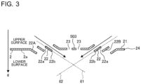
- FIG. 3 is a schematic cross-sectional view of a flat-plate portion of a corrugated fin according to Embodiment 1 as taken along the direction of flow of air.
- the diagonal solid arrows in FIG. 3 indicate the flow of condensed water.
- the corrugated fin 2 is joined to flat surfaces 1a of flat heat-transfer tubes 1 except for an upstream protruding portion 2a protruding further upstream in the direction of flow of air than the flat heat-transfer tubes 1. These junctions are brazed and joined by a brazing filler metal.
- the corrugated fin 2 is formed by a fin material such as an aluminum alloy.
- the fin material by which the corrugated fin 2 is formed has a surface cladded with a brazing filler metal layer.
- the clad brazing filler metal layer is made mainly of, for example, a brazing filler metal containing aluminum-silicon aluminum. Note here that the thickness of the fin material by which the corrugated fin 2 is formed ranges, for example, from approximately 50 ⁇ m to 200 ⁇ m.
- the corrugated fin 2 is formed such that fin sections 24, which are plate-shaped, are joined together one after another in a wave shape in the tube axial direction.
- the corrugated fin 2 is shaped such that the fin sections 24 are joined together one after another in the tube axial direction at alternately reversed inclinations when the corrugated fin 2 is seen from an angle parallel with the direction of flow of air.
- Each of the fin sections 24 includes a flat-plate portion 21, which is tabular-shaped, and apices 20 curved at both respective ends of the flat-plate portion 21 in the tube side-by-side placement direction.
- the corrugated fin 2 has its apices 20 joined to the flat heat-transfer tubes 1 by making surface contact with the flat surfaces 1a of the flat heat-transfer tubes 1.
- Each of the fin sections 24 has a plurality of louvers 22 formed and arranged in the direction of flow of air.
- Each of the louvers 22 includes a louver slit 22a through which air passes and a plate portion 22b that guides air to the louver slit 22a.
- the plate portion 22b is inclined to the flat-plate portion 21.
- the louver slit 22a and the plate portion 22b are each formed in the shape of a rectangle extending in the tube side-by-side placement direction.
- the louver 22 is formed by the plate portion 22b being cut and raised from the flat-plate portion 21.
- the plurality of louvers 22 are divided into a first louver group 22A formed further upstream in the direction of flow of air than the after-mentioned drain slits 23 formed in the fin section 24 and a second louver group 22B formed further downstream in the direction of flow of air than the drain slits 23.
- l1 is an imaginary auxiliary line to the midpoint of the through-thickness direction of a plate portion 22b of the first louver group 22A and l2 is an imaginary auxiliary line to the midpoint of the through-thickness direction of a plate portion 22b of the second louver group 22B.
- the plate portion 22b of the first louver group 22A and the plate portion 22b of the second louver group 22B are inclined in directions set so that the auxiliary line l1 and the auxiliary line l2 to the respective midpoints intersect each other below the lower surface.
- the plate portion 22b of the first louver group 22A and the plate portion 22b of the second louver group 22B are inclined to the flat-plate portion 21 and inclined in respective directions that are opposite to each other. Since the plate portions 22b of the louvers 22 are formed in such directions, condensed water having flowed along the plate portions 22b of the louvers 22 formed in a fin section 24 is guided toward the drain slits 23 in a next fin section 24 below. Therefore, the heat exchanger 10, which has this configuration, can bring about great improvement in drainage capacity.
- Each of the fin sections 24 has drain slits 23 through which condensed water produced on the fin section 24 is drained.
- the drain slits 23 are through holes opened in the corrugated fin 2.
- Each of the drain slits 23 is formed in the shape of a rectangle that extends in the tube side-by-side placement direction.
- the drain slits 23 are formed in a central portion of the fin section 24 in the direction of flow of air excluding the upstream protruding portion 2a.
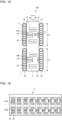
- FIG. 1 shows an example of the formation of drain slits 23 in two rows in the direction of flow of air, the row counts of drain slits 23 may be one or may be larger than or equal to three.
- drain slits 23 in a plurality of rows a region of the fin section 24 situated between each adjacent two of the rows is a heat-transfer region 503.
- the drain slits 23 of the plurality of rows are adjacent to each other in a central portion of the fin section 24 in the direction of flow of air excluding the upstream protruding portion 2a.
- adjacent to each other means that there is no louver 22 between the drain slits 23.
- the temperatures of surfaces of the flat heat-transfer tubes 1 and the corrugated fins 2 are lower than the temperature of air passing through the heat exchanger 10. This causes moisture in the air to condense into condensed water 4 on the surfaces of the flat heat-transfer tubes 1 and the corrugated fins 2.
- Condensed water 4 produced on a surface of the fin section 24 of a corrugated fin 2 flows down onto a next fin section 24 below through the drain slits 23. At this time, in a region of the surface of the fin section 24 where there is a large amount of condensed water 4, the condensed water 4 easily flows on the surface of the fin section 24 and easily flows down through the drain slits 23.
- Embodiment 1 brings about improvement in drainage capacity by locating drain slits 23 in the following positions.
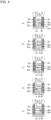
- FIG. 4 is an explanatory diagram of the positions of drain slits in fin sections of a corrugated fin according to Embodiment 1.
- Parts (a) to (e) of FIG. 4 correspond to fin sections 24 located in positions indicated by respective parts (a) to (e) of FIG. 1 . That is, parts (a) to (e) of FIG. 4 show fin sections 24 adjacent to one another in the tube axial direction.
- Parts (a) to (c) of FIG. 4 each show a configuration in which there are a total of four drain slits formed by drain slits 23 being formed in two rows in the direction of flow of air with each row formed by two drain slits 23 in the tube side-by-side placement direction.
- Parts (d) and (e) of FIG. 4 each show a configuration in which there are a total of two drain slits formed by drain slits 23 being formed in two rows each formed by one drain slit 23.
- the drain slits 23 are placed so that drain slits 23 in fin sections 24 adjacent to each other in the tube axial direction are displaced from each other in the tube side-by-side placement direction.
- Such placement of the drain slits 23 causes drained condensed water to flow in the following way through the corrugated fin 2.
- the flow of condensed water is described here with reference to two fin sections 24 adjacent one above the other.
- the aforementioned flow of condensed water is repeated in sequence in the up-down direction between two fin sections 24 adjacent to each other in the tube axial direction, and less condensed water 4 is thus retained on the surface of each fin section 24. This leads to efficient drainage.
- the drain slits 23 are formed to, when the drain slits 23 are seen from an angle parallel with the tube axial direction, overlap the apices 20 at both respective ends of the flat-plate portion 21 in the tube side-by-side placement direction.
- 24 of the drain slits are formed to, when 24 of the drain slits are seen from an angle parallel with the tube axial direction, overlap the apex 20 at one end of the flat-plate portion 21 in the tube side-by-side placement direction.
- drain apex 20a a portion of a fin section 24 in which a drain slit 23 overlaps an apex 20
- non-drain apex 20b a portion of a fin section 24 in which a drain slit 23 does not overlap an apex 20
- the drain slits 23 form two rows each formed by two drain slits 23 overlapping the apices 20 at both respective ends of the fin section 24 in the tube side-by-side placement direction. For this reason, in each of parts (a) to (c) of FIG. 4 , the fin section 24 has four drain apices 20a.
- the drain slits 23 form two rows each formed by one drain slit 23 overlapping the apex 20 at one end (right in FIG. 4 ) of the fin section 24 in the tube side-by-side placement direction. For this reason, the fin section 24 of part (d) of FIG. 4 has two drain apices 20a. In part (d) of FIG. 4 , each row is not formed by any one drain slit 23 overlapping the apex 20 at the other end (left in FIG. 4 ) of the fin section 24 in the tube side-by-side placement direction. For this reason, the fin section 24 of part (d) of FIG. 4 has two non-drain apices 20b.
- the drain slits 23 form two rows each formed by one drain slit 23 overlapping the apex 20 at one end (left in FIG. 4 ) of the fin section 24 in the tube side-by-side placement direction.
- the fin section 24 of part (e) of FIG. 4 has two drain apices 20a.
- each row is not formed by any one drain slit 23 overlapping the apex 20 at the other end (right in FIG. 4 ) of the fin section 24 in the tube side-by-side placement direction.
- the fin section 24 of part (d) of FIG. 4 has two non-drain apices 20b.
- each of the apices 20 is a portion formed by bending a tabular-shaped fin material into the shape of letter V, that apex 20 has a narrow inner space (see FIG. 6 , which will be described later). Therefore, condensed water 4 produced on an inner surface of an apex 20 easily builds up by being retained in the inner space of the apex 20 by the surface tension of the condensed water 4. For this reason, the drain apices 20a of the apices 20 make it possible to prevent condensed water from building up in the inner spaces of the apices 20 and bring about improvement in drainage capacity.
- Such a configuration makes it possible to expect improvement in drainage capacity while reducing deterioration of heat-transfer performance without decreasing the area of contact between the flat heat-transfer tubes 1 and the corrugated fin 2.
- FIG. 4 has shown examples in each of which the drain slits 23 are formed in positions at which, when the drain slits 23 are seen from an angle parallel with the tube axial direction, the drain slits 23 overlap the apices 20 at both respective ends of the flat-plate portion 21 in the tube side-by-side placement direction, the drain slits 23 may be formed in positions indicated by FIG. 5 .
- FIG. 5 is a diagram showing a modification of the heat exchanger according to Embodiment 1. Part (a) of FIG. 5 shows an upper one of fin sections 24 adjacent to each other in the tube axial direction, and part (b) of FIG. 5 shows a lower one of the fin sections 24 adjacent to each other in the tube axial direction.
- FIG. 6 is an explanatory diagram of the flow of condensed water in the configuration of FIG. 5 .
- the drain slits 23 are formed in positions, when the drain slits 23 are seen from an angle parallel with the tube axial direction, at which the drain slits 23 do not overlap the apices 20 at both respective ends of the flat-plate portion 21 in the tube side-by-side placement direction.
- the flow of condensed water in the modification of FIG. 5 is described with reference to FIG. 6 .
- the upper fin section 24A corresponds to the fin section 24 of part (a) of FIG. 5
- the lower fin section 24B corresponds to the fin section 24 of part (b) of FIG. 5 .
- the apex 20 between the fin section 24A and the fin section 24B is a non-drain apex 20b.
- the surface tension of the condensed water 4 causes condensed water to easily build up in the inner space of the non-drain apex 20b.
- apex built-up portion 30 a portion in which condensed water 4 has built up. The following describes drainage of the condensed water 4 having built up in the apex built-up portion 30.
- the drain slit 23 formed in the fin section 24C and the drain slit 23 formed in the fin section 24A are displaced from each other in the tube side-by-side placement direction (right-left direction in FIG. 6 ). For this reason, condensed water 4 having flowed down through an end (here, a left end in FIG.
- FIG. 7 is a diagram showing an example of a result of analysis of drainage characteristics according to the row counts of drain slits.
- the vertical axis represents the amount of water remaining in a heat exchanger, and the horizontal axis represents time. A higher speed of reduction in the amount of remaining water indicates higher drainage capacity.
- Drainage capacity is the amount of water that is drained per unit time. In general, measurements of drainage capacity are made in the following manner.
- FIG. 7 is a tabulation of examples of computational results yielded by simulating the aforementioned test evaluations using a two-phase gas-liquid three-dimensional analysis developed by the inventors.
- drain slits 23 it is found from FIG. 7 that a larger row counts of drain slits 23 further brings about higher drainage capacity.
- a reason for this is that the formation of drain slits 23 in a plurality of rows makes it possible to increase the total opening area of drain slits 23 in one fin section 24.
- an increase in opening area of a drain slit 23 is slightly effective in bringing about improvement in drainage capacity and, on the other hand, causes a great deterioration in performance due to a reduction in heat-transfer area.
- Configuring drain slits 23 in a plurality of rows so that the drain slits 23 have longer inner peripheral lengths is thus effective in bringing about improvement in drainage capacity. This allows the heat exchanger 10 to improve drainage capacity while reducing deterioration of heat-transfer performance.
- the foregoing allows the heat exchanger 10 to, by having drain slits 23 in a plurality of rows between the first louver group 22A and the second louver group 22B, improve drainage capacity while maintaining heat-transfer performance.
- the inventors found out through an experiment and an analysis that there is a relationship between the ratio of an inter-louver air passage cross-sectional area AL to a drain slit opening area As and drainage velocity. This point is explained below.
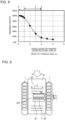
- FIG. 8 is a diagram showing an example of a graph representing a relationship between the ratio of an inter-louver air passage cross-sectional area AL to a drain slit opening area As and drainage capacity.
- Drainage capacity is the amount of water that is drained per unit time, and higher drainage capacity means that a larger amount of water is drained per unit time.
- FIG. 8 shows as an example a graph of a result of analysis showing a relationship in a case in which drainage capacity is defined as 100% in a case in which the ratio of the inter-louver air passage cross-sectional area AL to the drain slit opening area As is 0.25. As in the case of FIG.
- FIG. 9 is a diagram showing the dimensions of each component for use in a description of the relationship of FIG. 8 , and is a schematic plan view of part of a heat exchanger.
- FIG. 10 is an explanatory diagram of the dimensions of each component for use in the description of the relationship of FIG. 8 , and is a schematic cross-sectional view of a fin section as taken along the direction of flow of air.
- Drainage velocity is greatly affected by the ratio of the inter-louver air passage cross-sectional area AL to the drain slit opening area As.
- the drain slit opening area As is defined as Ns ⁇ Sw ⁇ Ss.
- the foregoing makes it possible, with AL/As being greater than or equal to 1 and less than or equal to 4, to effectively improve drainage capacity and ensure heat-transfer performance by providing drain slits 23.
- the graph of the relationship of FIG. 8 also applies to a corrugated fin 2, such as that described in Embodiment 4 below, in which the upstream protruding portion 2a of a fin section 24 is thickened. Further, the graph of the relationship of FIG. 8 also applies to a corrugated fin 2 provided with louvers 22 and drain slits 23 regardless of the number or placement of drain slits 23.
- a heat exchanger having corrugated fins 2 provided with louvers 22 and drain slits 23 and satisfying 1 ⁇ AL/As ⁇ 4 can improve drainage capacity while maintaining heat-transfer capacity.
- hs denotes the length of the heat-transfer region 503 (indicated by half-tone dot meshing in FIG. 9 ) in the direction of flow of air. This length hs is described below.
- a heat-transfer region 503 (see FIGS. 9 and 10 ) is formed between drain slits.
- the heat-transfer region 503 is low in heat-transfer efficiency as a heat transfer surface, as it is a region surrounded by the drain slits 23.
- the heat-transfer region 503 generates a vortex and exerts a heat-transfer enhancement effect downstream of the heat-transfer region 503 through turbulence enhancement.
- improvement in heat-transfer performance can be brought about when the length hs of the heat-transfer region 503 in the direction of flow of air is shorter than the length Ss of a drain slit 23 in the direction of flow of air. Further, according to an analysis by the inventors, improvement in drainage capacity can be brought about as will be described below when the length hs of the heat-transfer region 503 in the direction of flow of air is shorter than the length Ss of a drain slit 23 in the direction of flow of air.
- the distance between drain slits 23 adjacent to each other in the direction of flow of air becomes shortened when the length hs of the heat-transfer region 503 in the direction of flow of air is shorter than the length Ss of a drain slit 23 in the direction of flow of air.
- the distance between drain slits 23 adjacent to each other in the direction of flow of air becomes shortened, drops of water falling from the drain slits 23 merge into a single great drop of water and fall. That is, the two narrow drain slits 23 serve as one wide slit. Therefore, the effect of improvement in drainage capacity is considered to be greater when the length hs of the heat-transfer region 503 in the direction of flow of air is shorter than the length Ss of a drain slit 23 in the direction of flow of air.
- the heat-transfer region 503 and the drain slits 23 are alternately present in the direction of flow of air.
- this configuration is equivalent to a configuration in which a narrow bridge extending in the tube side-by-side placement direction (right-left direction in FIG. 9 ) is built in the middle of one large hole in the direction of flow of air and the large hole is divided into a plurality of holes.
- this bridge is equivalent to the heat-transfer region 503. Setting up a configuration in which the heat-transfer region 503 equivalent to a narrow bridge is provided as a mechanism for improvement in drainage capacity is considered to make it easy for water to be guided along the heat-transfer region 503 toward the center of the space between the two drain slits 23.
- a heat exchanger in which the length hs of the heat-transfer region 503 in the direction of flow of air is shorter than the length Ss of a drain slit 23 in the direction of flow of air can improve drainage capacity while maintaining heat-transfer capacity.
- the heat-transfer region 503 acts as a holder to inhibit warpage deformation of a fin material from occurring during punching of drain slits 23 through the fin material. This point is explained with reference to a corrugated fin of a comparative example including no heat-transfer region 503.
- FIG. 11 is an explanatory diagram of warpage deformation during punching in the corrugated fin of the comparative example.
- FIG. 11 shows a fin material yet to be subjected to corrugating. Dotted lines extending in a longitudinal direction in FIG. 11 indicate border lines between fin sections.
- the fin material 500 of the comparative example does not include a heat-transfer region 503 but has one large opening 500a that is to become a drain slit.
- the opening 500a is disposed in a central part of the fin material 500 in the direction of flow of air excluding the upstream protruding portion 2a. For this reason, the opening 500a deviates to one side of the fin material 500 from a center line 504 in the direction of flow of air.
- moment is produced on the side (upper side in FIG. 11 ) to which the opening 500a deviates, and warpage of the fin material 500 occurs, resulting in deformation.
- a corrugated fin 2 of Embodiment 1 is equivalent to a configuration in which one large opening 500a in the comparative example is divided into a plurality of small openings. In this configuration, a heat-transfer region 503 is formed between small openings. In other words, a fin material portion that is not a hole is formed between small openings. For this reason, this fin material portion acts as a holder to inhibit warpage deformation, and the corrugated fin 2 of Embodiment 1 can improve warpage deformation.
- louver angles greatly affect drainage capacity. This point is explained below.
- FIG. 12 is a diagram showing an example of a result of analysis of drainage characteristics according to louver angles.
- the vertical axis represents the amount of water remaining in a heat exchanger
- the horizontal axis represents time. A higher speed of reduction in the amount of remaining water indicates higher drainage capacity. This analysis is conducted in the following manner.
- a computation model of a heat exchanger having fin sections provided with louvers having a louver angle of 15°, a computation model of a heat exchanger having fin sections provided with louvers having a louver angle of 20°, a computation model of a heat exchanger having fin sections provided with louvers having a louver angle of 30°, and a computation model of a heat exchanger having fin sections provided with louvers having a louver angle of 40° are prepared. Then, the heat exchangers are put into water in a tank and taken out again, and the amount of water remaining in each heat exchanger is measured with passage of time using a two-phase gas-liquid three-dimensional analysis developed by the inventors. The result of analysis of FIG. 12 is a tabulation of these results of measurement.
- louver angle leads to an increase in speed of reduction in the amount of remaining water and higher drainage capacity.
- a possible reason for this is that an increase in louver angle leads to a greater gravitational drainage effect to facilitate the breakage of surface tension of condensed water on the surfaces of the louvers 22.
- the degree of the rise relatively decreases once the louver angle exceeds 30°.
- an increase in louver angle leads to an increase in air passage resistance on the plate portions 22b of the louvers 22, making it hard for air to flow. Therefore, in view of compatibility between improvement in drainage capacity and ease of flow of air, it is preferable that the louver angle range from 15° to 30°.
- a corrugated fin 2 be formed such that there is a well-balanced mixture of drain apices 20a and non-drain apices 20b.
- a fin material yet to be subjected to corrugating needs only be processed so that drain slits 23 are placed in any of the following patterns.
- FIGS. 13 to 16 below show tabular-shaped fin materials yet to be subjected to corrugating.
- dotted lines extending in a longitudinal direction in FIGS. 13 to 16 indicate border lines l3 between fin sections.
- FIG. 13 is an explanatory diagram of a pattern of placement 1 of openings for drain slits in a corrugated fin according to Embodiment 1. It is a diagram showing a fin material of.
- the width L2 of an opening 23a that is to become a drain slit 23 is longer than the length L1 of a fin section 24 in the tube side-by-side placement direction.
- the openings 23a of adjacent fin sections 24 are equally spaced from one another. That is, the length L3 of each space is the same in every place in a direction parallel with the length of the fin material 50.
- the openings 23a are placed across the border lines l3.
- a fin material 50 yet to be subjected to corrugating is processed so that openings 23a that are to become drain slits 23 are sized and placed in the foregoing pattern, and a corrugated fin 2 subjected to corrugating thus can be formed such that there is a well-balanced mixture of drain apices 20a and non-drain apices 20b.
- FIG. 14 is an explanatory diagram of a pattern of placement 2 of openings for drain slits in a corrugated fin according to Embodiment 1.
- the width L2 of an opening 23a that is to become a drain slit 23 is shorter than the length L1 of a fin section 24 in the tube side-by-side placement direction.
- the openings 23a of adjacent fin sections 24 are equally spaced from one another. That is, the length L3 of each space is the same in every place in a direction parallel with the length of the fin material 50. It should be noted that the length L3 is a value other than a value obtained by subtracting L2 from L1.
- a reason for this is that if L3 is a value obtained by subtracting L2 from L1, there is a possibility that all apices 20 are either drain apices 20a or non-drain apices 20b instead of being a mixture of drain apices 20a and non-drain apices 20b.
- a fin material 50 yet to be subjected to corrugating is processed so that openings 23a that are to become drain slits 23 are sized and placed in the foregoing pattern, and a corrugated fin 2 subjected to corrugating thus can be formed such that there is a well-balanced mixture of drain apices 20a and non-drain apices 20b.
- FIG. 15 is an explanatory diagram of a pattern of placement 3 of openings for drain slits in a corrugated fin according to Embodiment 1.
- the width L2 of an opening 23a that is to become a drain slit 23 is shorter than the length L1 of a fin section 24 in the tube side-by-side placement direction.
- the openings 23a of adjacent fin sections 24 are not equally spaced from one another. That is, the length L3 of each space is different in every place in a direction parallel with the length of the fin material 50.
- the pattern 3 is formed such that with one cycle being a pattern of placement having five openings 23a in a direction parallel with the length of the fin material 50, this pattern of placement is periodically repeated in a direction parallel with the length of the fin material 50.
- a fin material 50 yet to be subjected to corrugating is processed so that openings 23a that are to become drain slits 23 are sized and placed in the foregoing pattern, and a corrugated fin 2 subjected to corrugating thus can be formed such that there is a well-balanced mixture of drain apices 20a and non-drain apices 20b.
- a corrugated fin 2 subjected to corrugating thus can be formed such that there is a well-balanced mixture of drain apices 20a and non-drain apices 20b.
- the proportion of drain apices 20a to non-drain apices 20b in one corrugated fin 2 can be adjusted by adjusting L3, a balance between drainage capacity and heat-transfer performance can be achieved on the basis of design.
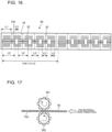
- FIG. 16 is an explanatory diagram of a pattern of placement 4 of openings for drain slits in a corrugated fin according to Embodiment 1.
- the width L2 of an opening 23a that is to become a drain slit 23 is different in every place.
- the openings 23a of adjacent fin sections 24 are equally spaced from one another. That is, the length L3 of each space is the same in every place in a direction parallel with the length of the fin material 50.
- the pattern 4 is formed such that with one cycle being a pattern of placement having five openings 23a in a direction parallel with the length of the fin material 50, this pattern of placement is periodically repeated in a direction parallel with the length of the fin material 50.
- a fin material 50 yet to be subjected to corrugating is processed so that openings 23a that are to become drain slits 23 are sized and placed in the foregoing pattern, and a corrugated fin 2 subjected to corrugating thus can be formed such that there is a well-balanced mixture of drain apices 20a and non-drain apices 20b.
- a balance between drainage capacity and heat-transfer performance can be achieved on the basis of design.
- the fin material 50 is formed such that a particular pattern of placement is periodically repeated in a direction parallel with the length of the fin material 50.
- a corrugated fin 2 fabricated by subjecting the fin material 50 to corrugating is formed such that fin sections 24 are identical in position of the drain slits 23 to each other in the tube side-by-side placement direction and are periodically and repeatedly located every several fin sections in the tube axial direction.
- the heat exchanger 10 can be configured as a result such that there is a well-balanced mixture of drain apices 20a and non-drain apices 20b. This results in making it possible to obtain a heat exchanger 10 with improved drainage capacity while maintaining heat-transfer performance.
- processing of drain slits 23 can be performed with corrugated cutters, corrugated punching rollers, or other devices.
- FIG. 17 shows how punching is performed with corrugated cutters.
- FIG. 17 is an explanatory diagram of punching of drain slits by corrugated cutters.
- Two corrugated cutters 501 and 502 are placed opposite each other, and a fin material 50 is placed between the two corrugated cutters 501 and 502.
- the fin material 50 is fed in the direction of an arrow outlined with a blank inside, and the two corrugated cutters 501 and 502 thus rotate in the directions of solid arrows. While the two corrugated cutters 501 and 502 are rotating, openings 23a that are to become drain slits 23 are punched in the fin material 50.
- the processing speed at which a corrugated fin 2 is manufactured can be increased.
- the present invention is not limited to a configuration in which a pattern of placement is periodically repeated, although manufacturing cannot be performed with corrugated cutters in a case in which a pattern of placement is not configured to be periodically repeated.
- the heat exchanger 10 of Embodiment 1 is a heat exchanger including the plurality of flat heat-transfer tubes 1 each formed in a flat shape in cross-section, provided with a plurality of flow passages formed by through holes, and placed side by side and spaced from one another in a direction orthogonal to a direction of flow of air; and the corrugated fin 2 placed between the plurality of flat heat-transfer tubes 1.
- the corrugated fin 2 is formed such that the fin sections 24, which are plate-shaped, are joined together one after another in a wave shape in a tube axial direction of the plurality of flat heat-transfer tubes 1.
- the fin sections 24 each have a drain slit 23 formed such that the drain slit extends in a tube side-by-side placement direction of the plurality of flat heat-transfer tubes 1 and the plurality of louvers 22 each having a louver slit 22a extending in the tube side-by-side placement direction and a plate portion 22b inclined to a flat-plate portion 21, which is tabular-shaped, in the fin section 24.
- the plurality of louvers 22 are divided into a first louver group 22A formed further upstream in the direction of flow of air than the drain slit 23 and a second louver group 22B formed further downstream in the direction of flow of air than the drain slit 23.
- the plate portions 22b of the first louver group 22A and the plate portions 22b of the second louver group 22B are inclined to the flat-plate portion 21 and inclined in respective directions that are opposite to each other.
- the heat exchanger 10 has a plurality of drain slits 23 in a plurality of respective rows between the first louver group 22A and the second louver group 22B.
- the heat exchanger 10 of Embodiment 1 can improve drainage capacity while maintaining heat-transfer capacity.
- the heat exchanger 10 of Embodiment 1 can improve drainage capacity while maintaining heat-transfer capacity.
- the drain slits 23 of the plurality of rows are formed adjacent to each other in a plurality of rows in the direction of flow of air. Therefore, the length hs in the direction of flow of air of a heat-transfer region 503 that is a region of the fin section 24 interposed in the direction of flow of air by the drain slits 23 provided in a plurality of rows is shorter than the length Ss of each of the drain slits 23 in the direction of flow of air.
- the heat exchanger 10 of Embodiment 1 can improve drainage capacity while maintaining heat-transfer capacity.
- the angle of the plate portion 22b of each of the plurality of louvers 22 inclined to the flat-plate portion 21 ranges from 15° to 30°.
- the heat exchanger 10 of Embodiment 1 can achieve compatibility between improvement in drainage capacity and ease of flow of air.
- the flat-plate portion 21 has two ends in the tube side-by-side placement direction and the fin section 24 has, at each of the two ends of the flat-plate portion 21, an apex 20 joined to the plurality of flat heat-transfer tubes 1.
- Some of the plurality of fin sections 24 have the drain slits 23 formed in positions at which the drain slits 23 overlap the apices 20 at one or both of the two ends when the drain slits 23 are seen from an angle parallel with the tube axial direction. Further, some of the plurality of fin sections 24 have the drain slits 23 formed in positions at which the drain slits 23 do not overlap both of the apices 20 at the two ends when the drain slits 23 are seen from an angle parallel with the tube axial direction.
- the heat exchanger 10 of Embodiment 1 can achieve a balance between drainage capacity and heat-transfer performance on the basis of design.
- drain slits 23 in ones of the fin sections adjacent to each other in the tube axial direction are displaced from each other in the tube side-by-side placement direction.
- the heat exchanger 10 of Embodiment 1 can improve drainage capacity.
- the corrugated fin 2 is formed such that ones of the fin sections 24 identical in position of the drain slits 23 to each other in the direction of flow of air are periodically and repeatedly located in the tube axial direction.
- the foregoing configuration makes it possible to obtain a heat exchanger 10 with improved drainage capacity while maintaining heat-transfer performance.
- Embodiment 2 relates to a configuration including a plurality of the heat exchangers 10 of Embodiment 1 in the direction of flow of air. The following description is focused on points of difference of Embodiment 2 from Embodiment 1, and configurations of Embodiment 2 that are similar to those of Embodiment 1 are not described.
- FIG. 18 is an enlarged schematic plan view of part of a heat exchanger according to Embodiment 2.
- FIG. 19 is a diagram showing a pattern of placement of openings for drain slits in a corrugated fin of the heat exchanger of FIG. 18 .
- the heat exchanger 10A according to Embodiment 2 is formed such that a plurality of flat heat-transfer tubes 1 are placed in two rows that are spaced from one another in the direction of flow of air and a corrugated fin 2 is provided commonly for the two rows.
- flat heat-transfer tubes 1 located windward are defined as flat heat-transfer tubes 1A
- flat heat-transfer tubes 1 located leeward are defined as flat heat-transfer tubes 1B.
- the dimension L4 in a long direction of a flat cross-section of a flat heat-transfer tube 1A and the dimension L5 in a long direction of a flat cross-section of a flat heat-transfer tube 1B may be equal to or different from each other.
- the flat heat-transfer tubes 1 are formed in two rows here, there may be three or more rows.
- the corrugated fin 2 of the heat exchanger 10A according to Embodiment 2 is provided commonly for the flat heat-transfer tubes 1A and the flat heat-transfer tubes 1B, and are joined to the flat heat-transfer tubes 1A and the flat heat-transfer tubes 1B by brazing.
- the corrugated fin 2 includes louvers 22 and drain slits 23 in correspondence with each row.
- Drain slits 23 located windward are first drain slits 23A formed in a range corresponding to the length in a long direction of a flat cross-section of a flat heat-transfer tube 1A.
- a plurality of louvers 22 located windward are divided into a first louver group 22A formed further upstream in the direction of flow of air than the first drain slits 23A and a second louver group 22B formed further downstream in the direction of flow of air than the drain slits 23.
- the plate portions 22b of the first louver group 22A and the plate portions 22b of the second louver group 22B are inclined to the flat-plate portion 21 and inclined in respective directions that are opposite to each other.
- Drain slits 23 located leeward are second drain slits 23B formed in a range corresponding to the length in a long direction of a flat cross-section of a flat heat-transfer tube 1B.
- a plurality of louvers 22 located leeward are divided into a first louver group 22A formed further upstream in the direction of flow of air than the second drain slits 23B and a second louver group 22B formed further downstream in the direction of flow of air than the second drain slits 23B.
- the plate portions 22b of the first louver group 22A and the plate portions 22b of the second louver group 22B are inclined to the flat-plate portion 21 and inclined in respective directions that are opposite to each other.
- first drain slits 23A and two rows of second drain slits 23B are formed in the direction of flow of air and one row is formed by two first drain slits 23A and another row is formed by two second drain slits 23B in the tube side-by-side placement direction, this configuration is not intended to impose any limitation. Further, although, in FIGS.
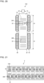
- the first drain slits 23A and the second drain slits 23B are identical in position in the tube side-by-side placement direction to each other in the fin section 24, the first drain slits 23A and the second drain slits 23B may be different in position in the tube side-by-side placement direction from each other in the fin section 24 as shown in FIGS. 20 and 21 .
- FIG. 20 is an enlarged schematic plan view of part of a modification of the heat exchanger according to Embodiment 2.
- FIG. 21 is a diagram showing a pattern of placement of openings for drain slits in a corrugated fin of the heat exchanger of FIG. 19 .
- the first drain slits 23A and the second drain slits 23B are different in position in the tube side-by-side placement direction from each other in the fin section 24.
- drainage capacity and heat-transfer performance can be adjusted separately for the windward side and the leeward side by adjusting the positions of the drain slits 23 or the widths of the drain slits 23.
- drainage capacity can be improved by increasing the number of drain apices 20a by adjusting the positions of the drain slits 23, and heat-transfer performance can be improved by reducing the number of drain apices 20a.
- drainage capacity can be improved by increasing the widths of the drain slits 23, and heat-transfer performance can be improved by reducing the widths of the drain slits 23.
- the positions of the drain slits 23 in the following manner. That is, the number of drain apices 20a located windward in one corrugated fin 2 is defined as N, and the number of drain apices 20a located leeward is defined as M. In this case, the positions of the first drain slits 23A and the second drain slits 23B are adjusted so that N > M is satisfied. This makes it possible to configure a heat exchanger such that drainage is prioritized on the windward side and heat transfer is prioritized on the leeward side.
- a sum of drain slit widths of the plurality of first drain slits 23A located windward in one corrugated fin 2 is defined as Sw F
- a sum of drain slit widths of the plurality of second drain slits 23B located windward is defined as Sw B .
- the heat exchanger 10A can be thus formed such that heat transfer is prioritized on the leeward side, the difference in heat-transfer performance between the windward side and the leeward side can be reduced. Since the difference in heat-transfer performance between the windward side and the leeward side can be reduced, the thickness of frost that forms on surfaces of the fin sections under low-temperature air conditions can be made almost uniform. Since the thickness of frost that forms on the surfaces of the fin sections can be made almost uniform, heat exchange performance under low-temperature air conditions is improved as a result.
- the heat exchanger 10A of Embodiment 2 brings about the following effects in addition to effects that are similar to those of Embodiment 1.
- the heat exchanger 10A of Embodiment 2 is formed such that the plurality of flat heat-transfer tubes 1 arranged in the tube side-by-side placement direction are placed in a plurality of rows and are spaced from one another in the direction of flow of air and the corrugated fin 2 is provided commonly for the plurality of rows.
- This configuration makes it possible to adjust drainage capacity and heat-transfer performance on the windward side and the leeward side by adjusting either or both the positions and drain slit widths of the first drain slits 23A and the second drain slit 23B in each row. This allows the heat exchanger 10A of Embodiment 2 to improve heat exchange performance under low-temperature air conditions.
- Embodiment 3 relates to a configuration in which the heat exchanger 10A of Embodiment 2 further includes an interrow drain slit.
- the following description is focused on points of difference of Embodiment 3 from Embodiment 2, and configurations of Embodiment 3 that are similar to those of Embodiment 2 are not described.
- FIG. 22 is an enlarged schematic plan view of part of a heat exchanger according to Embodiment 3.
- the heat exchanger 10B according to Embodiment 3 is formed such that an interrow drain slit 23C is formed in a non-junction region 21a that is not joined to the flat heat-transfer tubes 1.
- the non-junction region 21a is a portion of the flat-plate portion 21 situated between the flat heat-transfer tubes 1A and the flat heat-transfer tubes 1B.
- the interrow drain slit 23 is a through hole opened in the corrugated fin 2. Providing the interrow drain slit 23C in the non-junction region 21a makes it possible to improve drain capacity in a region where there is a decrease in heat-transfer performance.
- interrow drain slits 23C are formed in two rows in the direction of flow of air, there may be one row formed by an interrow drain slit 23C or three or more rows formed by an interrow drain slit 23C. Further, although, in FIG. 22 , the interrow drain slits 23C of the two rows are aligned in the tube side-by-side placement direction, the interrow drain slits 23C may be displaced as shown in FIG. 23 .
- FIG. 23 is an enlarged schematic plan view of part of a modification of a heat exchanger according to Embodiment 3.
- the interrow drain slits 23C of the two rows are displaced from each other in the tube side-by-side placement direction.
- FIG. 24 is a cross-sectional view taken along line A-A in FIGS. 22 and 23 .
- the dot-and-dash line of FIG. 24 is a center line indicating the middle positions in the direction of flow of air of interrow drain slits 23C formed in two rows.
- the arrows of FIG. 24 indicate the flow of condensed water during drainage.
- the heat exchanger 10B of Embodiment 3 uses the interrow drain slits 23C as main drain slits.
- the interrow drain slits 23C are drain slits that divide the plurality of louvers 22 into the first louver group 22A and the second louver group 22B. That is, the first louver group 22A is a louver group located further upstream in the direction of flow of air than the interrow drain slits 23C, and the second louver group 22B is a louver group located further downstream in the direction of flow of air than the interrow drain slits 23C.
- the plate portions 22b of the first louver group 22A and the plate portions 22b of the second louver group 22B are inclined to the flat-plate portion 21 and inclined in respective directions that are opposite to each other.
- Such a configuration causes condensed water having flowed along the plate portions 22b of the louvers 22 to be guided toward the interrow drain slits 23C of a lower fin section 24, making it possible to improve drainage capacity.
- each of the interrow drain slits 23C is larger than the opening area of each of the first drain slits 23A and the second drain slits 23B. In this configuration, condensed water is guided toward the interrow drain slits 23C. For this reason, since the opening area of each of the interrow drain slits 23C is larger than the opening area of each of the first drain slits 23A and the second drain slits 23B, higher drainage capacity can be achieved than in a case in which the opening areas are equal to each other.
- each of the interrow drain slits 23C be larger than the opening area of each of the first drain slits 23A and the second drain slits 23B, the opening areas may be equal to each other.
- an interrow drain slit 23C may be formed in one row, it is more preferable for a greater effect of improvement in drainage capacity that interrow drain slits 23C be formed in a plurality of rows.
- the first drain slits 23A, the second drain slits 23B, and the interrow drain slits 23C may be aligned to or displaced from each other in the tube side-by-side placement direction.
- the configuration of FIG. 23 is smaller than the configuration of FIG. 22 in terms of the area of a heat-transfer region 503 that is formed between the interrow drain slits 23C of the of the two rows in the direction of flow of air.
- the heat-transfer region 503 is indicated by half-tone dot meshing.
- the heat-transfer region 503 can be said to be a low-strength portion, as it is formed between the interrow drain slits 23C.
- the configuration FIG. 23 makes it possible to make the area of this low-strength portion smaller than the area in the configuration of FIG. 23 , thus making it possible to configure a heat exchanger with higher fin strength than the heat exchanger of the configuration of FIG. 22 .
- the heat exchanger 10B of Embodiment 3 can bring about improvement in drainage capacity in addition to effects that are similar to those of Embodiment 2, as the interrow drain slits 23C are formed in a position corresponding to a space between each adjacent two of the rows of flat heat-transfer tubes 1 in the direction of flow of air.
- the plate portions 22b of the first louver group 22A located further upstream in the direction of flow of air than the interrow drain slits 23C and the plate portions 22b of the second louver group 22B located further downstream in the direction of flow of air than the interrow drain slits 23C are inclined to the flat-plate portion 21 and inclined in respective directions that are opposite to each other.
- each of the interrow drain slits 23C is larger than the opening area of each of the first drain slits 23A and the second drain slits 23B, which are drain slits other than the interrow drain slits, higher drainage capacity can be achieved than in a case in which the opening areas are equal to each other.
- Embodiment 4 is formed such that the upstream protruding portion 2a of a fin section 24 in the heat exchanger 10B of Embodiment 3 is thickened.
- the following description is focused on points of difference of Embodiment 4 from Embodiment 3, and configurations of Embodiment 4 that are similar to those of Embodiment 3 are not described.
- FIG. 25 is an enlarged schematic plan view of part of a heat exchanger according to Embodiment 4.
- FIG. 26 is a cross-sectional view taken along line B-B in FIG. 25 .
- the thickness of the upstream protruding portion 2a of the corrugated fin 2 is greater than the thickness of a portion of the corrugated fin 2 other than the upstream protruding portion 2a.
- the upstream protruding portion 2a is formed to be thick by folding back a portion of the fin section 24 protruding further upstream than the flat heat-transfer tubes 1.
- Embodiment 4 is formed such that the upstream protruding portion 2a of the corrugated fin 2 is thicker than a portion of the corrugated fin 2 that is other than the upstream protruding portion 2a. This makes it possible to ensure the strength of the upstream protruding portion 2a and inhibit deformation of the upstream protruding portion 2a in case of frost formation.
- the heat exchanger 10C of Embodiment 4 brings about the following effects in addition to effects that are similar to those of Embodiment 3, as the upstream protruding portion 2a of the corrugated fin 2 is thicker than a portion of the corrugated fin 2 that is other than the upstream protruding portion 2a. That is, the strength of the upstream protruding portion 2a can be improved, and deformation of the upstream protruding portion 2a in a case in which frost forms on the upstream protruding portion 2a can be inhibited. When the upstream protruding portion 2a deforms, the flow passage of air is prevented, with the result that a deterioration in heat exchange capacity is invited. However, in Embodiment 4, heat exchange capacity can be maintained since deformation of the upstream protruding portion 2a can be inhibited.
- the upstream protruding portion 2a thickened by folding back a portion of the fin protruding further upstream than the flat heat-transfer tubes 1. This makes it possible to easily form a thick upstream protruding portion 2a. From the point of view of ensuring the strength of the upstream protruding portion 2a, it is conceivable that the thickness of the whole corrugated fin may be increased. However, in this case, the thicknesses of the plate portions 22b of the louvers 22 increase too. This causes a decrease in the inter-louver air passage cross-sectional area and causes a deterioration in the capacity of drainage of condensed water through the space between the louvers.
- Embodiment 4 is formed such that the upstream protruding portion 2a of the flat-plate portion 21 is thickened in the heat exchanger of Embodiment 3
- Embodiment 4 may be formed such that the upstream protruding portion 2a of the flat-plate portion 21 is thickened in the heat exchanger of Embodiment 1 or 2.
- Embodiment 5 relates to an air-conditioning apparatus as an example of a refrigeration cycle apparatus including a heat exchanger of any of Embodiments 1 to 4.
- FIG. 27 is a diagram showing a configuration of an air-conditioning apparatus according to Embodiment 5.
- the air-conditioning apparatus uses a heat exchanger of any of Embodiments 1 to 4 as an outdoor heat exchanger 230. Note, however, that this is not intended to impose any limitation.
- a heat exchanger of any of Embodiments 1 to 4 may be used as an indoor heat exchanger 110, or heat exchangers of any of Embodiments 1 to 4 may be used as both the outdoor heat exchanger 230 and the indoor heat exchanger 110.
- the air-conditioning apparatus forms a refrigerant circuit in which an outdoor unit 200 and an indoor unit 100 are connected with a gas refrigerant pipe 300 and a liquid refrigerant pipe 400.
- the outdoor unit 200 includes a compressor 210, a four-way valve 220, the outdoor heat exchanger 230, and an outdoor fan 240.
- the compressor 210 compresses and discharges sucked refrigerant. Although not limited in particular, the compressor 210 can change the capacity of the compressor 210 by arbitrarily varying the operating frequency, for example, through an inverter circuit or other circuits.
- the four-way valve 220 is a valve configured to switch the flows of refrigerant between cooling operation and heating operation.
- the outdoor heat exchanger 230 exchanges heat between refrigerant and outdoor air.
- the outdoor heat exchanger 230 serves as an evaporator to evaporate and gasify the refrigerant.
- the outdoor heat exchanger 230 serves as a condenser to condense and liquefy the refrigerant.
- the outdoor fan 240 sends the outdoor air to the outdoor heat exchanger 230 and facilitates heat exchange at the outdoor heat exchanger 230.
- the indoor unit 100 includes the indoor heat exchanger 110, a decompression device 120, and an indoor fan 130.
- the indoor heat exchanger 110 exchanges heat between air in a room to be air-conditioned and refrigerant.
- the indoor heat exchanger 110 serves as a condenser to condense and liquefy the refrigerant.
- the indoor heat exchanger 110 serves as an evaporator to evaporate and gasify the refrigerant.
- the decompression device 120 decompresses and expands the refrigerant.
- the decompression device 120 is formed, for example, by an electronic expansion valve or other devices. In a case in which the decompression device 120 is formed by an electronic expansion valve, the decompression device 120 adjusts its opening degree in accordance with an instruction from a controller (not illustrated) or other devices.
- the indoor fan 130 passes the air in the room through the indoor heat exchanger 110 and supplies, into the room, the air passed through the indoor heat exchanger 110.
- heating operation is described.
- the four-way valve 220 is switched to a state illustrated by dotted lines of FIG. 27 .
- High-temperature and high-pressure gas refrigerant compressed and discharged by the compressor 210 passes through the four-way valve 220 and flows into the indoor heat exchanger 110.
- the gas refrigerant having flowed into the indoor heat exchanger 110 condenses and liquefies by exchanging heat with air in a space to be air-conditioned.
- the refrigerant having liquefied is decompressed by the decompression device 120 into two-phase gas-liquid refrigerant and then flows into the outdoor heat exchanger 230.
- the refrigerant having flowed into the outdoor heat exchanger 230 evaporates and gasifies by exchanging heat with outdoor air sent from the outdoor fan 240.
- the refrigerant having gasified passes through the four-way valve 220 and is sucked again into the compressor 210.
- Such circulation of the refrigerant causes the air-conditioning apparatus to perform air conditioning related to heating.
- cooling operation is described.
- the four-way valve 220 is switched to a state illustrated by solid lines of FIG. 27 .
- High-temperature and high-pressure gas refrigerant compressed and discharged by the compressor 210 passes through the four-way valve 220 and flows into the outdoor heat exchanger 230.
- the gas refrigerant having flowed into the outdoor heat exchanger 230 condenses and liquefies by exchanging heat with outdoor air supplied by the outdoor fan 240.
- the refrigerant having liquefied is decompressed by the decompression device 120 into two-phase gas-liquid refrigerant and then flows into the indoor heat exchanger 110.
- the refrigerant having flowed into the indoor heat exchanger 110 evaporates and gasifies by exchanging heat with air in the space to be air-conditioned.
- the refrigerant having gasified passes through the four-way valve 220 and is sucked again into the compressor 210.
- Such circulation of the refrigerant causes the air-conditioning apparatus to perform air conditioning related to cooling.
- Embodiment 5 Since the air-conditioning apparatus of Embodiment 5 includes a heat exchanger of any of Embodiments 1 to 4, it is possible to improve drainage capacity while maintaining heat-transfer performance in the heat exchanger.
- the refrigeration cycle apparatus has been described as being an air-conditioning apparatus, this is not intended to impose any limitation.
- the refrigeration cycle apparatus may be a cooling apparatus configured to cool, for example, a refrigerating-freezing warehouse, a hot water supply apparatus, or other apparatuses.
Landscapes
- Engineering & Computer Science (AREA)
- Physics & Mathematics (AREA)
- Thermal Sciences (AREA)
- Mechanical Engineering (AREA)
- General Engineering & Computer Science (AREA)
- Geometry (AREA)
- Heat-Exchange Devices With Radiators And Conduit Assemblies (AREA)
Abstract
Description
- The present invention relates to a heat exchanger including a corrugated fin and to a refrigeration cycle apparatus.
- For example, corrugated-fin-tube-type heat exchangers formed by alternately stacking flat heat-transfer tubes and corrugated fins are widespread. In a case in which such a heat exchanger is used as an evaporator, the surface temperature of a corrugated fin becomes lower than or equal to a freezing point, so that condensed water on a fin surface may freeze. The freezing of the condensed water on the fin surface mounts resistance to air passing through the heat exchanger, causing a deterioration in heat-transfer performance of the corrugated fin. To address this problem, there is a heat exchanger provided with a drain slit formed by a through hole in a corrugated fin so that condensed water on a fin surface is drained through the drain slit (see, for example, Patent Literature 1). It should be noted that the term "condensed water" refers to water having adhered to a surface of the heat exchanger as a result of condensation of moisture in the air.
- Patent Literature 1: Japanese Unexamined Patent Application Publication
JP 2015- 183 908 A - Although the heat exchanger of
Patent Literature 1 has a drain slit through which condensed water on a fin surface is drained, enlarging an opening of the drain slit for improvement in drainage capacity invites a deterioration in heat-transfer performance due to a reduction in heat-transfer area while bringing about improvement in drainage capacity. The heat exchanger ofPatent Literature 1 had room for improvement in terms of improving drainage capacity while maintaining heat-transfer performance. - To solve problems such as those noted above, the present invention has as an object to provide a heat exchanger that makes it possible to improve drainage capacity while maintaining heat-transfer performance and a refrigeration cycle apparatus.
- A heat exchanger according to an embodiment of the present invention includes a plurality of flat heat-transfer tubes each formed in a flat shape in cross-section, provided with a plurality of flow passages formed by through holes, and placed side by side and spaced from one another in a direction orthogonal to a direction of flow of air; and a corrugated fin placed between the plurality of flat heat-transfer tubes. The corrugated fin is formed such that fin sections that are plate-shaped are joined together one after another in a wave shape in a tube axial direction of the plurality of flat heat-transfer tubes, the fin sections each have a drain slit formed such that the drain slit extends in a tube side-by-side placement direction of the plurality of flat heat-transfer tubes, and a plurality of louvers each having a louver slit extending in the tube side-by-side placement direction and a plate portion inclined to a flat-plate portion that is tabular-shaped in the fin section, the plurality of louvers are divided into a first louver group formed further upstream in the direction of flow of air than the drain slit and a second louver group formed further downstream in the direction of flow of air than the drain slit, the plate portions of the first louver group and the plate portions of the second louver group are inclined to the flat-plate portion and inclined in respective directions that are opposite to each other, and the drain slit includes a plurality of drain slits provided in a plurality of respective rows between the first louver group and the second louver group.
- Further, a refrigeration cycle apparatus according to an embodiment of the present invention includes the aforementioned heat exchanger.
- By having drain slits in a plurality of rows between the first louver group and the second louver group, the heat exchanger according to an embodiment of the present invention makes it possible to improve drainage capacity while maintaining heat-transfer performance.
- Further, since the length of a heat-transfer region is longer than the length of a drain slit in the direction of flow of air, the heat exchanger according to an embodiment of the present invention makes it possible to improve drainage capacity while maintaining heat-transfer performance.
-
-
FIG. 1 is a diagram illustrating a configuration of a heat exchanger according toEmbodiment 1. -
FIG. 2 is a schematic perspective view of part of the heat exchanger according toEmbodiment 1. -
FIG. 3 is a schematic cross-sectional view of a flat-plate portion of a corrugated fin according toEmbodiment 1 as taken along a direction of flow of air. -
FIG. 4 is an explanatory diagram of the positions of drain slits in fin sections of a corrugated fin according toEmbodiment 1. -
FIG. 5 is a diagram showing a modification of the heat exchanger according toEmbodiment 1. -
FIG. 6 is an explanatory diagram of the flow of condensed water in the configuration ofFIG. 5 . -
FIG. 7 is a diagram showing an example of a result of analysis of drainage characteristics according to the row counts of drain slits. -
FIG. 8 is a diagram showing an example of a graph representing a relationship between the ratio of an inter-louver air passage cross-sectional area AL to a drain slit opening area As and drainage capacity. -
FIG. 9 is a diagram showing the dimensions of each component for use in a description of the relationship ofFIG. 8 . -
FIG. 10 is an explanatory diagram of the dimensions of each component for use in the description of the relationship ofFIG. 8 . -
FIG. 11 is an explanatory diagram of warpage deformation during punching in a corrugated fin of a comparative example. -
FIG. 12 is a diagram showing an example of a result of analysis of drainage characteristics according to louver angles. -
FIG. 13 is an explanatory diagram of a pattern ofplacement 1 of openings for drain slits in a corrugated fin according toEmbodiment 1. -
FIG. 14 is an explanatory diagram of a pattern ofplacement 2 of openings for drain slits in a corrugated fin according toEmbodiment 1. -
FIG. 15 is an explanatory diagram of a pattern ofplacement 3 of openings for drain slits in a corrugated fin according toEmbodiment 1. -
FIG. 16 is an explanatory diagram of a pattern ofplacement 4 of openings for drain slits in a corrugated fin according toEmbodiment 1. -
FIG. 17 is an explanatory diagram of punching of drain slits by corrugated cutters. -
FIG. 18 is an enlarged schematic plan view of part of a heat exchanger according toEmbodiment 2. -
FIG. 19 is a diagram showing a pattern of placement of openings for drain slits in a corrugated fin of the heat exchanger ofFIG. 18 . -
FIG. 20 is an enlarged schematic plan view of part of a modification of aheat exchanger 10 according toEmbodiment 2. -
FIG. 21 is a diagram showing a pattern of placement of openings for drain slits in a corrugated fin of the heat exchanger ofFIG. 19 . -
FIG. 22 is an enlarged schematic plan view of part of a heat exchanger according toEmbodiment 3. -
FIG. 23 is an enlarged schematic plan view of part of a modification of the heat exchanger according toEmbodiment 3. -
FIG. 24 is a cross-sectional view taken along line A-A inFIGS. 22 and23 . -
FIG. 25 is an enlarged schematic plan view of part of a heat exchanger according toEmbodiment 4. -
FIG. 26 is a cross-sectional view taken along line B-B inFIG. 25 . -
FIG. 27 is a diagram showing a configuration of an air-conditioning apparatus according to Embodiment 5. - In the following, heat exchangers and a refrigeration cycle apparatus according to embodiments are described, for example, with reference to the accompanying drawings. Further, constituent elements given identical reference signs in the following drawings are identical or equivalent to each other, and these reference signs are adhered to throughout the full text of the embodiments described below. Moreover, the forms of constituent elements expressed in the full text of the specification are merely examples and are not limited to forms described herein. In particular, a combination of constituent elements is not limited solely to a combination in one embodiment, but constituent elements described in one embodiment can be applied to another embodiment.
- Further, in the following description, an upper part of a drawing is described as an "upper side", and a lower part of a drawing is described as a "lower side". Furthermore, directive terms (such as "right" and "left") used to promote understanding are intended for descriptive purposes and are not intended to limit the present invention. Further, how high or low temperatures and humidities are is not determined in relation to particularly absolute values but relatively determined according to states, actions, or other conditions in apparatuses or other devices. Moreover, relationships in size between one constituent element and another in the drawings may be different from actual ones.
-
FIG. 1 is a diagram illustrating a configuration of a heat exchanger according toEmbodiment 1. As shown inFIG. 1 , theheat exchanger 10 ofEmbodiment 1 is a parallel-pipe corrugated-fin-tube-type heat exchanger. Theheat exchanger 10 includes a plurality of flat heat-transfer tubes 1, a plurality ofcorrugated fins 2, and a pair ofheaders 3. - The pair of
headers 3 are each a tube that is connected by pipes to other devices included in a refrigeration cycle apparatus, into and out of which refrigerant flows, and that causes the refrigerant to be divided or merged. The refrigerant is a fluid that serves as a heat exchange medium. The pair ofheaders 3 include aheader 3A and aheader 3B. Theheader 3A and theheader 3B are placed one above the other and spaced from one another. In a case in which theheat exchanger 10 is used as an evaporator, liquid refrigerant passes through theupper header 3B, and gas refrigerant passes through thelower header 3A. In a case in which theheat exchanger 10 is used as a condenser, gas refrigerant passes through theupper header 3B, and liquid refrigerant passes through thelower header 3A. - Between the two
headers 3, the plurality of flat heat-transfer tubes 1 are placed perpendicular to eachheader 3, and the plurality of flat heat-transfer tubes 1 are placed parallel to one another. The plurality of flat heat-transfer tubes 1 are placed side by side and equally spaced from one another in a direction orthogonal to a direction of flow of air. In the following, the direction (right-left direction inFIG. 1 ) in which the flat heat-transfer tubes 1 are placed side by side is referred to as "tube side-by-side placement direction", and the axial direction (up-down direction inFIG. 1 ) of the flat heat-transfer tubes 1 is referred to as "tube axial direction". - Each of the flat heat-
transfer tubes 1 has a flat shape in cross-section. Each of the flat heat-transfer tubes 1 is a heat-transfer tube of which an outer surface (hereinafter referred to as "flat surface") of a long side of the flat cross-section has the shape of a planar surface and of which an outer surface of a short side of the flat shape has the shape of a curved surface. Each of the flat heat-transfer tubes 1 is a multi-hole heat-transfer tube having a plurality of refrigerant flow passages formed by through holes inside the tube. The flat heat-transfer tubes 1 are disposed to stand in the up-down direction, have their through holes extending in the up-down direction, and communicate with the twoheaders 3. Each of the flat heat-transfer tubes 1 is placed so that a long side of the flat cross-section extends along the direction of flow of air. Each flat heat-transfer tube 1 is joined to the twoheaders 3 by having both ends inserted in and brazed to insertion holes (not illustrated) opened separately in each of the twoheaders 3. A usable example of a brazing filler metal is an aluminum-containing brazing filler metal. - Note here that in a case in which the
heat exchanger 10 is used as an evaporator, low-temperature and low-pressure refrigerant flows through the refrigerant flow passages inside the flat heat-transfer tubes 1. In a case in which theheat exchanger 10 is used as a condenser, high-temperature and high-pressure refrigerant flows through the refrigerant flow passages inside the flat heat-transfer tubes 1. The arrows inFIG. 1 indicate the flow of refrigerant in a case in which theheat exchanger 10 is used as an evaporator. -
Embodiment 1 is intended to describe drainage of condensed water that is produced on fin surfaces in a case in which theheat exchanger 10 is used as an evaporator. For this reason, the following describes the flow of refrigerant in theheat exchanger 10 in a case in which theheat exchanger 10 is used as an evaporator. As indicated by the arrows inFIG. 1 , the refrigerant flows into theheader 3A via a pipe (not illustrated) through which the refrigerant is supplied from an external device (not illustrated) to theheat exchanger 10. The refrigerant having flowed into theheader 3A is distributed and passes through each flat heat-transfer tube 1. - The flat heat-
transfer tube 1 exchanges heat between the refrigerant passing through the inside of the tube and outside air that is external atmospheric air passing through outside the tube. At this time, the refrigerant removes heat from the atmospheric air while passing through the flat heat-transfer tube 1. The refrigerant subjected to heat exchange through each flat heat-transfer tube 1 flows into theheader 3B and merges inside theheader 3B. The refrigerant having merged inside theheader 3B is refluxed to the external device (not illustrated) through a pipe (not illustrated) connected to theheader 3B. - Each of the
corrugated fins 2 is placed between one of the flat heat-transfer tubes 1 and another. Thecorrugated fins 2 are disposed to expand the area of heat transfer between the refrigerant and the outside air. Each of thecorrugated fins 2 is formed in a pleated wave shape by a tabular-shaped fin material being subjected to corrugating and bent into a zigzag pattern with repeated mountain folds and valley folds. Note here that bent portions in undulations formed in a wave shape serve as apices of the wave shape. InEmbodiment 1, the apices of each of thecorrugated fins 2 are arranged in a height direction. Parts (a) to (e) ofFIG. 1 will be described later. -
FIG. 2 is a schematic perspective view of part of the heat exchanger according toEmbodiment 1. The arrow outlined with a blank inside inFIG. 2 indicates the direction of flow of air.FIG. 3 is a schematic cross-sectional view of a flat-plate portion of a corrugated fin according toEmbodiment 1 as taken along the direction of flow of air. The diagonal solid arrows inFIG. 3 indicate the flow of condensed water. - The
corrugated fin 2 is joined to flat surfaces 1a of flat heat-transfer tubes 1 except for an upstream protrudingportion 2a protruding further upstream in the direction of flow of air than the flat heat-transfer tubes 1. These junctions are brazed and joined by a brazing filler metal. Thecorrugated fin 2 is formed by a fin material such as an aluminum alloy. Moreover, the fin material by which thecorrugated fin 2 is formed has a surface cladded with a brazing filler metal layer. The clad brazing filler metal layer is made mainly of, for example, a brazing filler metal containing aluminum-silicon aluminum. Note here that the thickness of the fin material by which thecorrugated fin 2 is formed ranges, for example, from approximately 50 µm to 200 µm. - The
corrugated fin 2 is formed such thatfin sections 24, which are plate-shaped, are joined together one after another in a wave shape in the tube axial direction. Thecorrugated fin 2 is shaped such that thefin sections 24 are joined together one after another in the tube axial direction at alternately reversed inclinations when thecorrugated fin 2 is seen from an angle parallel with the direction of flow of air. Each of thefin sections 24 includes a flat-plate portion 21, which is tabular-shaped, andapices 20 curved at both respective ends of the flat-plate portion 21 in the tube side-by-side placement direction. Thecorrugated fin 2 has itsapices 20 joined to the flat heat-transfer tubes 1 by making surface contact with the flat surfaces 1a of the flat heat-transfer tubes 1. - Each of the
fin sections 24 has a plurality oflouvers 22 formed and arranged in the direction of flow of air. Each of thelouvers 22 includes alouver slit 22a through which air passes and aplate portion 22b that guides air to thelouver slit 22a. Theplate portion 22b is inclined to the flat-plate portion 21. The louver slit 22a and theplate portion 22b are each formed in the shape of a rectangle extending in the tube side-by-side placement direction. Thelouver 22 is formed by theplate portion 22b being cut and raised from the flat-plate portion 21. - The plurality of
louvers 22 are divided into afirst louver group 22A formed further upstream in the direction of flow of air than the after-mentioned drain slits 23 formed in thefin section 24 and asecond louver group 22B formed further downstream in the direction of flow of air than the drain slits 23. - Note here that, in
FIG. 3 , l1 is an imaginary auxiliary line to the midpoint of the through-thickness direction of aplate portion 22b of thefirst louver group 22A and l2 is an imaginary auxiliary line to the midpoint of the through-thickness direction of aplate portion 22b of thesecond louver group 22B. As shown inFIG. 3 , when the flat-plate portion 21 has its upper and lower surfaces defined with reference to a direction of gravitational force g, theplate portion 22b of thefirst louver group 22A and theplate portion 22b of thesecond louver group 22B are inclined in directions set so that the auxiliary line l1 and the auxiliary line l2 to the respective midpoints intersect each other below the lower surface. - In other words, the
plate portion 22b of thefirst louver group 22A and theplate portion 22b of thesecond louver group 22B are inclined to the flat-plate portion 21 and inclined in respective directions that are opposite to each other. Since theplate portions 22b of thelouvers 22 are formed in such directions, condensed water having flowed along theplate portions 22b of thelouvers 22 formed in afin section 24 is guided toward the drain slits 23 in anext fin section 24 below. Therefore, theheat exchanger 10, which has this configuration, can bring about great improvement in drainage capacity. - Each of the
fin sections 24 has drain slits 23 through which condensed water produced on thefin section 24 is drained. The drain slits 23 are through holes opened in thecorrugated fin 2. Each of the drain slits 23 is formed in the shape of a rectangle that extends in the tube side-by-side placement direction. The drain slits 23 are formed in a central portion of thefin section 24 in the direction of flow of air excluding the upstream protrudingportion 2a. AlthoughFIG. 1 shows an example of the formation of drain slits 23 in two rows in the direction of flow of air, the row counts of drain slits 23 may be one or may be larger than or equal to three. In the case of the formation of drain slits 23 in a plurality of rows, a region of thefin section 24 situated between each adjacent two of the rows is a heat-transfer region 503. In the case of the formation of drain slits 23 in a plurality of rows, the drain slits 23 of the plurality of rows are adjacent to each other in a central portion of thefin section 24 in the direction of flow of air excluding the upstream protrudingportion 2a. The term "adjacent to each other" means that there is nolouver 22 between the drain slits 23. - In a case in which the
heat exchanger 10 is used as an evaporator, the temperatures of surfaces of the flat heat-transfer tubes 1 and thecorrugated fins 2 are lower than the temperature of air passing through theheat exchanger 10. This causes moisture in the air to condense intocondensed water 4 on the surfaces of the flat heat-transfer tubes 1 and thecorrugated fins 2.Condensed water 4 produced on a surface of thefin section 24 of acorrugated fin 2 flows down onto anext fin section 24 below through the drain slits 23. At this time, in a region of the surface of thefin section 24 where there is a large amount ofcondensed water 4, thecondensed water 4 easily flows on the surface of thefin section 24 and easily flows down through the drain slits 23. - Meanwhile, in a region of the surface of the
fin section 24 where there is a small amount ofcondensed water 4, thecondensed water 4 hardly flows on the surface of thefin section 24 and easily builds up by being retained on the surface of thefin section 24. It is known that such building-up occurs, although thefin section 24 is inclined when thefin section 24 is seen from an angle parallel with the direction of flow of air. To address this problem,Embodiment 1 brings about improvement in drainage capacity by locating drain slits 23 in the following positions. -
FIG. 4 is an explanatory diagram of the positions of drain slits in fin sections of a corrugated fin according toEmbodiment 1. Parts (a) to (e) ofFIG. 4 correspond tofin sections 24 located in positions indicated by respective parts (a) to (e) ofFIG. 1 . That is, parts (a) to (e) ofFIG. 4 show fin sections 24 adjacent to one another in the tube axial direction. Parts (a) to (c) ofFIG. 4 each show a configuration in which there are a total of four drain slits formed bydrain slits 23 being formed in two rows in the direction of flow of air with each row formed by twodrain slits 23 in the tube side-by-side placement direction. Parts (d) and (e) ofFIG. 4 each show a configuration in which there are a total of two drain slits formed bydrain slits 23 being formed in two rows each formed by one drain slit 23. - As shown in
FIG. 4 , the drain slits 23 are placed so that drain slits 23 infin sections 24 adjacent to each other in the tube axial direction are displaced from each other in the tube side-by-side placement direction. Such placement of the drain slits 23 causes drained condensed water to flow in the following way through thecorrugated fin 2. The flow of condensed water is described here with reference to twofin sections 24 adjacent one above the other. - Condensed water produced on the surface of the
upper fin section 24 flows down onto thelower fin section 24 through the drain slits 23 in theupper fin section 24. Note here that, as mentioned above, drain slits 23 infin sections 24 adjacent to each other in the tube axial direction are displaced from each other in the tube side-by-side placement direction. For this reason, part of a region directly below the drain slits 23 in theupper fin section 24 is a portion of thelower fin section 24 in which no drain slits 23 are formed and a portion in which condensed water is produced and retained. Therefore,condensed water 4 having fallen onto thelower fin section 24 through the drain slits 23 in theupper fin section 24 merges withcondensed water 4 having become stagnant by being retained on the surface of thelower fin section 24. Thecondensed water 4, which has increased in amount by merging, comes to easily flow down, and is drained through the drain slits 23 in thelower fin section 24. The aforementioned flow of condensed water is repeated in sequence in the up-down direction between twofin sections 24 adjacent to each other in the tube axial direction, and lesscondensed water 4 is thus retained on the surface of eachfin section 24. This leads to efficient drainage. - Incidentally, in each of parts (a) to (c) of
FIG. 4 , the drain slits 23 are formed to, when the drain slits 23 are seen from an angle parallel with the tube axial direction, overlap theapices 20 at both respective ends of the flat-plate portion 21 in the tube side-by-side placement direction. In each of parts (d) and (e) ofFIG. 4 ,24 of the drain slits are formed to, when 24 of the drain slits are seen from an angle parallel with the tube axial direction, overlap the apex 20 at one end of the flat-plate portion 21 in the tube side-by-side placement direction. In the following, a portion of afin section 24 in which a drain slit 23 overlaps an apex 20 is referred to as "drain apex 20a", and a portion of afin section 24 in which a drain slit 23 does not overlap an apex 20 is referred to as "non-drain apex 20b" for explanatory convenience. - In each of parts (a) to (c) of
FIG. 4 , the drain slits 23 form two rows each formed by twodrain slits 23 overlapping theapices 20 at both respective ends of thefin section 24 in the tube side-by-side placement direction. For this reason, in each of parts (a) to (c) ofFIG. 4 , thefin section 24 has fourdrain apices 20a. - In part (d) of
FIG. 4 , the drain slits 23 form two rows each formed by one drain slit 23 overlapping the apex 20 at one end (right inFIG. 4 ) of thefin section 24 in the tube side-by-side placement direction. For this reason, thefin section 24 of part (d) ofFIG. 4 has twodrain apices 20a. In part (d) ofFIG. 4 , each row is not formed by any one drain slit 23 overlapping the apex 20 at the other end (left inFIG. 4 ) of thefin section 24 in the tube side-by-side placement direction. For this reason, thefin section 24 of part (d) ofFIG. 4 has twonon-drain apices 20b. - In part (e) of
FIG. 4 , the drain slits 23 form two rows each formed by one drain slit 23 overlapping the apex 20 at one end (left inFIG. 4 ) of thefin section 24 in the tube side-by-side placement direction. For this reason, thefin section 24 of part (e) ofFIG. 4 has twodrain apices 20a. In part (e) ofFIG. 4 , each row is not formed by any one drain slit 23 overlapping the apex 20 at the other end (right inFIG. 4 ) of thefin section 24 in the tube side-by-side placement direction. For this reason, thefin section 24 of part (d) ofFIG. 4 has twonon-drain apices 20b. - Since each of the
apices 20 is a portion formed by bending a tabular-shaped fin material into the shape of letter V, that apex 20 has a narrow inner space (seeFIG. 6 , which will be described later). Therefore,condensed water 4 produced on an inner surface of an apex 20 easily builds up by being retained in the inner space of the apex 20 by the surface tension of thecondensed water 4. For this reason, thedrain apices 20a of theapices 20 make it possible to prevent condensed water from building up in the inner spaces of theapices 20 and bring about improvement in drainage capacity. It should be noted that although a larger number ofdrain apices 20a further bring about an effect of improvement in drainage capacity, increasing the number ofdrain apices 20a invites a deterioration in heat-transfer capacity, as theapices 20 are portions that are joined to the flat heat-transfer tubes 1 for heat transfer. Therefore, it is only necessary to determine the proportion of the number ofdrain apices 20a to the number ofnon-drain apices 20b in consideration of drainage capacity and heat-transfer capacity. Further, increasing the number ofdrain apices 20a invites a deterioration of strength by reducing the junctions between thefin sections 24 and the flat heat-transfer tubes 1. For this reason, a configuration is desirable in which there is a well-balanced allocation ofdrain apices 20a andnon-drain apices 20b throughout thecorrugated fin 2. - Such a configuration makes it possible to expect improvement in drainage capacity while reducing deterioration of heat-transfer performance without decreasing the area of contact between the flat heat-
transfer tubes 1 and thecorrugated fin 2. - Although
FIG. 4 has shown examples in each of which the drain slits 23 are formed in positions at which, when the drain slits 23 are seen from an angle parallel with the tube axial direction, the drain slits 23 overlap theapices 20 at both respective ends of the flat-plate portion 21 in the tube side-by-side placement direction, the drain slits 23 may be formed in positions indicated byFIG. 5 . -
FIG. 5 is a diagram showing a modification of the heat exchanger according toEmbodiment 1. Part (a) ofFIG. 5 shows an upper one offin sections 24 adjacent to each other in the tube axial direction, and part (b) ofFIG. 5 shows a lower one of thefin sections 24 adjacent to each other in the tube axial direction.FIG. 6 is an explanatory diagram of the flow of condensed water in the configuration ofFIG. 5 . - In
FIG. 5 , the drain slits 23 are formed in positions, when the drain slits 23 are seen from an angle parallel with the tube axial direction, at which the drain slits 23 do not overlap theapices 20 at both respective ends of the flat-plate portion 21 in the tube side-by-side placement direction. - The flow of condensed water in the modification of
FIG. 5 is described with reference toFIG. 6 . Of the twofin sections 24 that forms the apex 20 surrounded by a dotted circle inFIG. 6 , theupper fin section 24A corresponds to thefin section 24 of part (a) ofFIG. 5 , and thelower fin section 24B corresponds to thefin section 24 of part (b) ofFIG. 5 . - Since the
fin section 24A and thefin section 24B are placed such that the drain slits 23 do not overlap theapices 20 when the drain slits 23 are seen from an angle parallel with the tube axial direction, the apex 20 between thefin section 24A and thefin section 24B is a non-drain apex 20b. For this reason, the surface tension of thecondensed water 4 causes condensed water to easily build up in the inner space of thenon-drain apex 20b. In the following, a portion in whichcondensed water 4 has built up is referred to as "apex built-upportion 30". The following describes drainage of thecondensed water 4 having built up in the apex built-upportion 30. - Condensed water produced and accumulated on the surface of a
fin section 24C above thefin section 24A flows down toward thefin section 24A through the drain slit 23 in thefin section 24C. Note here that the drain slit 23 formed in thefin section 24C and the drain slit 23 formed in thefin section 24A are displaced from each other in the tube side-by-side placement direction (right-left direction inFIG. 6 ). For this reason,condensed water 4 having flowed down through an end (here, a left end inFIG. 6 ) of the drain slit 23 in thefin section 24C in the tube side-by-side placement direction passes through the drain slit 23 in thefin section 24A and merges with thecondensed water 4 having built up in the apex built-upportion 30. This merging causes thecondensed water 4 in the apex built-upportion 30 to flow out from the apex built-upportion 30 as a result of the breakage of the surface tension and flow on the surface of thefin section 24B as indicated by a dotted arrow inFIG. 6 . This manner can bring about improvement in drainage capacity offin sections 24 whose drain slits 23 are formed in positions at which the drain slits 23 do not overlapapices 20 when the drain slits 23 are seen from an angle parallel with the tube axial direction. -
FIG. 7 is a diagram showing an example of a result of analysis of drainage characteristics according to the row counts of drain slits. InFIG. 7 , the vertical axis represents the amount of water remaining in a heat exchanger, and the horizontal axis represents time. A higher speed of reduction in the amount of remaining water indicates higher drainage capacity. Drainage capacity is the amount of water that is drained per unit time. In general, measurements of drainage capacity are made in the following manner. An experimental model of a heat exchanger having fin sections each having a drain slit 23 forming one row, an experimental model of a heat exchanger having fin sections each including drain slits 23 each having the same opening area and forming two rows, and an experimental model of a heat exchanger having fin sections each including drain slits 23 each having the same opening area and forming three rows are fabricated. Then, each of the heat exchangers is put into water in a tank and taken out again, and the amount of water remaining in each heat exchanger is measured with passage of time.FIG. 7 is a tabulation of examples of computational results yielded by simulating the aforementioned test evaluations using a two-phase gas-liquid three-dimensional analysis developed by the inventors. - It is found from
FIG. 7 that a larger row counts of drain slits 23 further brings about higher drainage capacity. A reason for this is that the formation of drain slits 23 in a plurality of rows makes it possible to increase the total opening area of drain slits 23 in onefin section 24. - Further, in one example of a result of analysis by the inventors, a comparison of drainage capacity between a case in which two
drain slits 23 were provided and a case in which one drain slit 23 having the total opening area of the twodrain slits 23 was provided showed that higher drainage capacity can be attained in the case in which the twodrain slits 23 were provided. According to an analysis by the inventors, it was found that this improvement in drainage capacity is brought about by the following mechanism. Even with an increase in opening area of a drain slit 23, an area in the vicinity of the center of the drain slit 23 does not contribute to drainage, and in actuality, water flows down along an inner peripheral portion of the drain slit 23. Therefore, an increase in opening area of a drain slit 23 is slightly effective in bringing about improvement in drainage capacity and, on the other hand, causes a great deterioration in performance due to a reduction in heat-transfer area. Configuring drain slits 23 in a plurality of rows so that the drain slits 23 have longer inner peripheral lengths is thus effective in bringing about improvement in drainage capacity. This allows theheat exchanger 10 to improve drainage capacity while reducing deterioration of heat-transfer performance. - The foregoing allows the
heat exchanger 10 to, by having drain slits 23 in a plurality of rows between thefirst louver group 22A and thesecond louver group 22B, improve drainage capacity while maintaining heat-transfer performance. - The inventors found out through an experiment and an analysis that there is a relationship between the ratio of an inter-louver air passage cross-sectional area AL to a drain slit opening area As and drainage velocity. This point is explained below.
-
FIG. 8 is a diagram showing an example of a graph representing a relationship between the ratio of an inter-louver air passage cross-sectional area AL to a drain slit opening area As and drainage capacity. Drainage capacity is the amount of water that is drained per unit time, and higher drainage capacity means that a larger amount of water is drained per unit time.FIG. 8 shows as an example a graph of a result of analysis showing a relationship in a case in which drainage capacity is defined as 100% in a case in which the ratio of the inter-louver air passage cross-sectional area AL to the drain slit opening area As is 0.25. As in the case ofFIG. 7 , this result of analysis is a tabulation of examples of computational results yielded by putting heat exchangers into water in a tank, taking them out again, and calculating, at a given point of time, the amount of water remaining in each heat exchanger.FIG. 9 is a diagram showing the dimensions of each component for use in a description of the relationship ofFIG. 8 , and is a schematic plan view of part of a heat exchanger.FIG. 10 is an explanatory diagram of the dimensions of each component for use in the description of the relationship ofFIG. 8 , and is a schematic cross-sectional view of a fin section as taken along the direction of flow of air. - Drainage velocity is greatly affected by the ratio of the inter-louver air passage cross-sectional area AL to the drain slit opening area As. The inter-louver air passage cross-sectional area AL is defined as NL × Ls × Lw = NL × ((Lp × sinθ) - t) × Lw. The drain slit opening area As is defined as Ns × Sw × Ss.
- In these formulas,
- NL [-] is the number of
louvers 22, - θ [rad] is the angle of a
plate portion 22b inclined to a flat-plate portion 21 (hereinafter referred to as "louver angle"), - Lp [mm] is the pitch between
adjacent louvers 22, - Lw [mm] is the width of a
louver 22 in the tube side-by-side placement direction (hereinafter referred to as "louver width"), - t [mm] is the thickness of a corrugated fin,
- Ns [-] is the row counts of drain slits 23,
- Sw [mm] is the width of a drain slit 23 in the tube side-by-side placement direction (hereinafter referred to as "drain slit width"), and
- Ss [mm] is the length of a drain slit 23 in the direction of flow of air (hereinafter referred to as "drain slit length").
- With AL/As being greater than or equal to 4, a decrease in value of AL/As leads to a rise in drainage velocity and an increase in rate of the rise. Therefore, with the inter-louver air passage cross-sectional area AL being constant, an increase in the drain slit opening area As leads to a greater effect of improvement in drainage velocity. For this reason, increasing the drain slit opening area As by providing
drain slits 23 in a plurality of rows makes it possible to increase drainage velocity. - Note, however, that with AL/As lowered to less than 1, the rate of rise in drainage velocity to an increase in the drain slit opening area As decreases, although drainage velocity can be increased. A reason for this is that with AL/As being less than 1, the drain slit opening area As exceeds the inter-louver air passage cross-sectional area AL, so that the amount of water that is drained through the drain slits 23 is large and limits are put on the characteristics of drainage through the
louvers 22. Further, with AL/As being less than 1, heat-transfer performance decreases as the drain slit opening area As increases, albeit with high drainage velocity and high drainage capacity. For this reason, in view of a balance between drainage capacity and heat-transfer performance, it is preferable that AL/As ≥ 1. - Meanwhile, with AL/As being greater than 4, drainage velocity does not increase greatly although the drain slit opening area As increases. For this reason, making AL/As greater than 4 is not effective in bringing about improvement in drainage capacity. A possible reason why drainage velocity does not increase greatly although the drain slit opening area As increases is that condensed water guided by the
louvers 22 cannot be sufficiently handled by the drain slits 23 because the inter-louver air passage cross-sectional area AL is too great for the drain slit opening area As. - The foregoing makes it possible, with AL/As being greater than or equal to 1 and less than or equal to 4, to effectively improve drainage capacity and ensure heat-transfer performance by providing drain slits 23. The graph of the relationship of
FIG. 8 also applies to acorrugated fin 2, such as that described inEmbodiment 4 below, in which the upstream protrudingportion 2a of afin section 24 is thickened. Further, the graph of the relationship ofFIG. 8 also applies to acorrugated fin 2 provided withlouvers 22 and drain slits 23 regardless of the number or placement of drain slits 23. Therefore, a heat exchanger having corrugatedfins 2 provided withlouvers 22 and drain slits 23 and satisfying 1 ≤ AL/As ≤ 4 can improve drainage capacity while maintaining heat-transfer capacity. InFIGS. 9 and10 , hs denotes the length of the heat-transfer region 503 (indicated by half-tone dot meshing inFIG. 9 ) in the direction of flow of air. This length hs is described below. - In a case in which drain slits 23 are formed in a plurality of rows, a heat-transfer region 503 (see
FIGS. 9 and10 ) is formed between drain slits. The heat-transfer region 503 is low in heat-transfer efficiency as a heat transfer surface, as it is a region surrounded by the drain slits 23. However, the heat-transfer region 503 generates a vortex and exerts a heat-transfer enhancement effect downstream of the heat-transfer region 503 through turbulence enhancement. Because of the characteristics of turbulence enhancement, improvement in heat-transfer performance can be brought about when the length hs of the heat-transfer region 503 in the direction of flow of air is shorter than the length Ss of a drain slit 23 in the direction of flow of air. Further, according to an analysis by the inventors, improvement in drainage capacity can be brought about as will be described below when the length hs of the heat-transfer region 503 in the direction of flow of air is shorter than the length Ss of a drain slit 23 in the direction of flow of air. - The distance between drain slits 23 adjacent to each other in the direction of flow of air becomes shortened when the length hs of the heat-
transfer region 503 in the direction of flow of air is shorter than the length Ss of a drain slit 23 in the direction of flow of air. When the distance between drain slits 23 adjacent to each other in the direction of flow of air becomes shortened, drops of water falling from the drain slits 23 merge into a single great drop of water and fall. That is, the two narrow drain slits 23 serve as one wide slit. Therefore, the effect of improvement in drainage capacity is considered to be greater when the length hs of the heat-transfer region 503 in the direction of flow of air is shorter than the length Ss of a drain slit 23 in the direction of flow of air. - Meanwhile, when the length hs of the heat-
transfer region 503 in the direction of flow of air is longer than the length Ss of a drain slit 23 in the direction of flow of air, condensed water tends to remain on the heat-transfer region 503 and drops of water fall separately from each of the drain slits 23, although there is a benefit from the standpoint of strength increase. For this reason, it is considered that the effect of improvement in drainage capacity is low when the length hs of the heat-transfer region 503 in the direction of flow of air becomes longer than the length Ss of a drain slit 23 in the direction of flow of air. - Further, the heat-
transfer region 503 and the drain slits 23 are alternately present in the direction of flow of air. When this configuration is looked at differently, this configuration is equivalent to a configuration in which a narrow bridge extending in the tube side-by-side placement direction (right-left direction inFIG. 9 ) is built in the middle of one large hole in the direction of flow of air and the large hole is divided into a plurality of holes. Moreover, this bridge is equivalent to the heat-transfer region 503. Setting up a configuration in which the heat-transfer region 503 equivalent to a narrow bridge is provided as a mechanism for improvement in drainage capacity is considered to make it easy for water to be guided along the heat-transfer region 503 toward the center of the space between the two drain slits 23. - According to the foregoing, a heat exchanger in which the length hs of the heat-
transfer region 503 in the direction of flow of air is shorter than the length Ss of a drain slit 23 in the direction of flow of air can improve drainage capacity while maintaining heat-transfer capacity. - Incidentally, the heat-
transfer region 503 acts as a holder to inhibit warpage deformation of a fin material from occurring during punching of drain slits 23 through the fin material. This point is explained with reference to a corrugated fin of a comparative example including no heat-transfer region 503. -
FIG. 11 is an explanatory diagram of warpage deformation during punching in the corrugated fin of the comparative example.FIG. 11 shows a fin material yet to be subjected to corrugating. Dotted lines extending in a longitudinal direction inFIG. 11 indicate border lines between fin sections. - The
fin material 500 of the comparative example does not include a heat-transfer region 503 but has onelarge opening 500a that is to become a drain slit. Theopening 500a is disposed in a central part of thefin material 500 in the direction of flow of air excluding the upstream protrudingportion 2a. For this reason, theopening 500a deviates to one side of thefin material 500 from acenter line 504 in the direction of flow of air. When theopening 500a deviates to one side in this manner, moment is produced on the side (upper side inFIG. 11 ) to which theopening 500a deviates, and warpage of thefin material 500 occurs, resulting in deformation. - On the other hand, a
corrugated fin 2 ofEmbodiment 1 is equivalent to a configuration in which onelarge opening 500a in the comparative example is divided into a plurality of small openings. In this configuration, a heat-transfer region 503 is formed between small openings. In other words, a fin material portion that is not a hole is formed between small openings. For this reason, this fin material portion acts as a holder to inhibit warpage deformation, and thecorrugated fin 2 ofEmbodiment 1 can improve warpage deformation. - According to an experiment and an analysis by the inventors, it was found that louver angles greatly affect drainage capacity. This point is explained below.
-
FIG. 12 is a diagram showing an example of a result of analysis of drainage characteristics according to louver angles. InFIG. 12 , the vertical axis represents the amount of water remaining in a heat exchanger, and the horizontal axis represents time. A higher speed of reduction in the amount of remaining water indicates higher drainage capacity. This analysis is conducted in the following manner. A computation model of a heat exchanger having fin sections provided with louvers having a louver angle of 15°, a computation model of a heat exchanger having fin sections provided with louvers having a louver angle of 20°, a computation model of a heat exchanger having fin sections provided with louvers having a louver angle of 30°, and a computation model of a heat exchanger having fin sections provided with louvers having a louver angle of 40° are prepared. Then, the heat exchangers are put into water in a tank and taken out again, and the amount of water remaining in each heat exchanger is measured with passage of time using a two-phase gas-liquid three-dimensional analysis developed by the inventors. The result of analysis ofFIG. 12 is a tabulation of these results of measurement. - It is found from
FIG. 12 that an increase in louver angle leads to an increase in speed of reduction in the amount of remaining water and higher drainage capacity. A possible reason for this is that an increase in louver angle leads to a greater gravitational drainage effect to facilitate the breakage of surface tension of condensed water on the surfaces of thelouvers 22. Moreover, while an increase in louver angle leads to an increase in speed of reduction in the amount of remaining water, the degree of the rise relatively decreases once the louver angle exceeds 30°. Further, an increase in louver angle leads to an increase in air passage resistance on theplate portions 22b of thelouvers 22, making it hard for air to flow. Therefore, in view of compatibility between improvement in drainage capacity and ease of flow of air, it is preferable that the louver angle range from 15° to 30°. - As mentioned above, it is desirable that a
corrugated fin 2 be formed such that there is a well-balanced mixture ofdrain apices 20a andnon-drain apices 20b. In achieving such a configuration, a fin material yet to be subjected to corrugating needs only be processed so that drain slits 23 are placed in any of the following patterns. Four patterns of placement of drain slits 23 in a fin material are described below with reference toFIGS. 13 to 16 below.FIGS. 13 to 16 below show tabular-shaped fin materials yet to be subjected to corrugating. Further, dotted lines extending in a longitudinal direction inFIGS. 13 to 16 indicate border lines l3 between fin sections. -
FIG. 13 is an explanatory diagram of a pattern ofplacement 1 of openings for drain slits in a corrugated fin according toEmbodiment 1. It is a diagram showing a fin material of. - In the pattern of
placement 1, the width L2 of anopening 23a that is to become a drain slit 23 is longer than the length L1 of afin section 24 in the tube side-by-side placement direction. Theopenings 23a ofadjacent fin sections 24 are equally spaced from one another. That is, the length L3 of each space is the same in every place in a direction parallel with the length of thefin material 50. Theopenings 23a are placed across the border lines l3. Afin material 50 yet to be subjected to corrugating is processed so thatopenings 23a that are to become drain slits 23 are sized and placed in the foregoing pattern, and acorrugated fin 2 subjected to corrugating thus can be formed such that there is a well-balanced mixture ofdrain apices 20a andnon-drain apices 20b. -
FIG. 14 is an explanatory diagram of a pattern ofplacement 2 of openings for drain slits in a corrugated fin according toEmbodiment 1. - In the pattern of
placement 2, the width L2 of anopening 23a that is to become a drain slit 23 is shorter than the length L1 of afin section 24 in the tube side-by-side placement direction. Theopenings 23a ofadjacent fin sections 24 are equally spaced from one another. That is, the length L3 of each space is the same in every place in a direction parallel with the length of thefin material 50. It should be noted that the length L3 is a value other than a value obtained by subtracting L2 from L1. A reason for this is that if L3 is a value obtained by subtracting L2 from L1, there is a possibility that allapices 20 are eitherdrain apices 20a ornon-drain apices 20b instead of being a mixture ofdrain apices 20a andnon-drain apices 20b. Afin material 50 yet to be subjected to corrugating is processed so thatopenings 23a that are to become drain slits 23 are sized and placed in the foregoing pattern, and acorrugated fin 2 subjected to corrugating thus can be formed such that there is a well-balanced mixture ofdrain apices 20a andnon-drain apices 20b. -
FIG. 15 is an explanatory diagram of a pattern ofplacement 3 of openings for drain slits in a corrugated fin according toEmbodiment 1. - In the pattern of
placement 3, the width L2 of anopening 23a that is to become a drain slit 23 is shorter than the length L1 of afin section 24 in the tube side-by-side placement direction. Moreover, theopenings 23a ofadjacent fin sections 24 are not equally spaced from one another. That is, the length L3 of each space is different in every place in a direction parallel with the length of thefin material 50. Thepattern 3 is formed such that with one cycle being a pattern of placement having fiveopenings 23a in a direction parallel with the length of thefin material 50, this pattern of placement is periodically repeated in a direction parallel with the length of thefin material 50. - A
fin material 50 yet to be subjected to corrugating is processed so thatopenings 23a that are to become drain slits 23 are sized and placed in the foregoing pattern, and acorrugated fin 2 subjected to corrugating thus can be formed such that there is a well-balanced mixture ofdrain apices 20a andnon-drain apices 20b. In particular, because the proportion ofdrain apices 20a tonon-drain apices 20b in onecorrugated fin 2 can be adjusted by adjusting L3, a balance between drainage capacity and heat-transfer performance can be achieved on the basis of design. -
FIG. 16 is an explanatory diagram of a pattern ofplacement 4 of openings for drain slits in a corrugated fin according toEmbodiment 1. - In the pattern of
placement 4, the width L2 of anopening 23a that is to become a drain slit 23 is different in every place. Moreover, theopenings 23a ofadjacent fin sections 24 are equally spaced from one another. That is, the length L3 of each space is the same in every place in a direction parallel with the length of thefin material 50. Thepattern 4 is formed such that with one cycle being a pattern of placement having fiveopenings 23a in a direction parallel with the length of thefin material 50, this pattern of placement is periodically repeated in a direction parallel with the length of thefin material 50. - A
fin material 50 yet to be subjected to corrugating is processed so thatopenings 23a that are to become drain slits 23 are sized and placed in the foregoing pattern, and acorrugated fin 2 subjected to corrugating thus can be formed such that there is a well-balanced mixture ofdrain apices 20a andnon-drain apices 20b. In particular, because the proportion ofdrain apices 20a tonon-drain apices 20b in onecorrugated fin 2 can be adjusted by adjusting L2, a balance between drainage capacity and heat-transfer performance can be achieved on the basis of design. - In any of the foregoing patterns of
placement 1 to 4, thefin material 50 is formed such that a particular pattern of placement is periodically repeated in a direction parallel with the length of thefin material 50. For this reason, acorrugated fin 2 fabricated by subjecting thefin material 50 to corrugating is formed such thatfin sections 24 are identical in position of the drain slits 23 to each other in the tube side-by-side placement direction and are periodically and repeatedly located every several fin sections in the tube axial direction. By having this configuration, theheat exchanger 10 can be configured as a result such that there is a well-balanced mixture ofdrain apices 20a andnon-drain apices 20b. This results in making it possible to obtain aheat exchanger 10 with improved drainage capacity while maintaining heat-transfer performance. - In a case, such as the patterns of
placement 1 to 4, in which a particular pattern of placement is periodically repeated in a direction parallel with the length of thefin material 50, processing of drain slits 23 can be performed with corrugated cutters, corrugated punching rollers, or other devices.FIG. 17 shows how punching is performed with corrugated cutters. -
FIG. 17 is an explanatory diagram of punching of drain slits by corrugated cutters. - Two
corrugated cutters fin material 50 is placed between the twocorrugated cutters fin material 50 is fed in the direction of an arrow outlined with a blank inside, and the twocorrugated cutters corrugated cutters openings 23a that are to become drain slits 23 are punched in thefin material 50. - By thus using corrugated cutters or corrugated punching rollers for processing of drain slits 23, the processing speed at which a
corrugated fin 2 is manufactured can be increased. The present invention is not limited to a configuration in which a pattern of placement is periodically repeated, although manufacturing cannot be performed with corrugated cutters in a case in which a pattern of placement is not configured to be periodically repeated. - As described above, the
heat exchanger 10 ofEmbodiment 1 is a heat exchanger including the plurality of flat heat-transfer tubes 1 each formed in a flat shape in cross-section, provided with a plurality of flow passages formed by through holes, and placed side by side and spaced from one another in a direction orthogonal to a direction of flow of air; and thecorrugated fin 2 placed between the plurality of flat heat-transfer tubes 1. Thecorrugated fin 2 is formed such that thefin sections 24, which are plate-shaped, are joined together one after another in a wave shape in a tube axial direction of the plurality of flat heat-transfer tubes 1. Thefin sections 24 each have a drain slit 23 formed such that the drain slit extends in a tube side-by-side placement direction of the plurality of flat heat-transfer tubes 1 and the plurality oflouvers 22 each having alouver slit 22a extending in the tube side-by-side placement direction and aplate portion 22b inclined to a flat-plate portion 21, which is tabular-shaped, in thefin section 24. The plurality oflouvers 22 are divided into afirst louver group 22A formed further upstream in the direction of flow of air than the drain slit 23 and asecond louver group 22B formed further downstream in the direction of flow of air than the drain slit 23. Theplate portions 22b of thefirst louver group 22A and theplate portions 22b of thesecond louver group 22B are inclined to the flat-plate portion 21 and inclined in respective directions that are opposite to each other. Theheat exchanger 10 has a plurality of drain slits 23 in a plurality of respective rows between thefirst louver group 22A and thesecond louver group 22B. - According to the foregoing configuration, the
heat exchanger 10 ofEmbodiment 1 can improve drainage capacity while maintaining heat-transfer capacity. - Further, the
heat exchanger 10 ofEmbodiment 1 is formed such that when the inter-louver air passage cross-sectional area AL is defined as AL = ((Lp × sinθ) - t) × NL × Lw and the drain slit opening area As is defined as As = Ns × Sw × Ss, 1 ≤ AL/As ≤ 4 is satisfied. - According to the foregoing configuration, the
heat exchanger 10 ofEmbodiment 1 can improve drainage capacity while maintaining heat-transfer capacity. - The drain slits 23 of the plurality of rows are formed adjacent to each other in a plurality of rows in the direction of flow of air. Therefore, the length hs in the direction of flow of air of a heat-
transfer region 503 that is a region of thefin section 24 interposed in the direction of flow of air by the drain slits 23 provided in a plurality of rows is shorter than the length Ss of each of the drain slits 23 in the direction of flow of air. - According to the foregoing configuration, the
heat exchanger 10 ofEmbodiment 1 can improve drainage capacity while maintaining heat-transfer capacity. - The angle of the
plate portion 22b of each of the plurality oflouvers 22 inclined to the flat-plate portion 21 ranges from 15° to 30°. - According to the foregoing configuration, the
heat exchanger 10 ofEmbodiment 1 can achieve compatibility between improvement in drainage capacity and ease of flow of air. - The flat-
plate portion 21 has two ends in the tube side-by-side placement direction and thefin section 24 has, at each of the two ends of the flat-plate portion 21, an apex 20 joined to the plurality of flat heat-transfer tubes 1. Some of the plurality offin sections 24 have the drain slits 23 formed in positions at which the drain slits 23 overlap theapices 20 at one or both of the two ends when the drain slits 23 are seen from an angle parallel with the tube axial direction. Further, some of the plurality offin sections 24 have the drain slits 23 formed in positions at which the drain slits 23 do not overlap both of theapices 20 at the two ends when the drain slits 23 are seen from an angle parallel with the tube axial direction. - According to the foregoing configuration, the
heat exchanger 10 ofEmbodiment 1 can achieve a balance between drainage capacity and heat-transfer performance on the basis of design. - The drain slits 23 in ones of the fin sections adjacent to each other in the tube axial direction are displaced from each other in the tube side-by-side placement direction.
- According to the foregoing configuration, the
heat exchanger 10 ofEmbodiment 1 can improve drainage capacity. - The
corrugated fin 2 is formed such that ones of thefin sections 24 identical in position of the drain slits 23 to each other in the direction of flow of air are periodically and repeatedly located in the tube axial direction. - The foregoing configuration makes it possible to obtain a
heat exchanger 10 with improved drainage capacity while maintaining heat-transfer performance. -
Embodiment 2 relates to a configuration including a plurality of theheat exchangers 10 ofEmbodiment 1 in the direction of flow of air. The following description is focused on points of difference ofEmbodiment 2 fromEmbodiment 1, and configurations ofEmbodiment 2 that are similar to those ofEmbodiment 1 are not described. -
FIG. 18 is an enlarged schematic plan view of part of a heat exchanger according toEmbodiment 2.FIG. 19 is a diagram showing a pattern of placement of openings for drain slits in a corrugated fin of the heat exchanger ofFIG. 18 . - The
heat exchanger 10A according toEmbodiment 2 is formed such that a plurality of flat heat-transfer tubes 1 are placed in two rows that are spaced from one another in the direction of flow of air and acorrugated fin 2 is provided commonly for the two rows. Here, flat heat-transfer tubes 1 located windward are defined as flat heat-transfer tubes 1A and flat heat-transfer tubes 1 located leeward are defined as flat heat-transfer tubes 1B. The dimension L4 in a long direction of a flat cross-section of a flat heat-transfer tube 1A and the dimension L5 in a long direction of a flat cross-section of a flat heat-transfer tube 1B may be equal to or different from each other. Although the flat heat-transfer tubes 1 are formed in two rows here, there may be three or more rows. - The
corrugated fin 2 of theheat exchanger 10A according toEmbodiment 2 is provided commonly for the flat heat-transfer tubes 1A and the flat heat-transfer tubes 1B, and are joined to the flat heat-transfer tubes 1A and the flat heat-transfer tubes 1B by brazing. Thecorrugated fin 2 includeslouvers 22 and drain slits 23 in correspondence with each row. - Drain slits 23 located windward are
first drain slits 23A formed in a range corresponding to the length in a long direction of a flat cross-section of a flat heat-transfer tube 1A. A plurality oflouvers 22 located windward are divided into afirst louver group 22A formed further upstream in the direction of flow of air than thefirst drain slits 23A and asecond louver group 22B formed further downstream in the direction of flow of air than the drain slits 23. Although not illustrated, theplate portions 22b of thefirst louver group 22A and theplate portions 22b of thesecond louver group 22B are inclined to the flat-plate portion 21 and inclined in respective directions that are opposite to each other. - Drain slits 23 located leeward are second drain slits 23B formed in a range corresponding to the length in a long direction of a flat cross-section of a flat heat-
transfer tube 1B. A plurality oflouvers 22 located leeward are divided into afirst louver group 22A formed further upstream in the direction of flow of air than the second drain slits 23B and asecond louver group 22B formed further downstream in the direction of flow of air than the second drain slits 23B. Although not illustrated, theplate portions 22b of thefirst louver group 22A and theplate portions 22b of thesecond louver group 22B are inclined to the flat-plate portion 21 and inclined in respective directions that are opposite to each other. - Although, in
FIG. 18 , two rows offirst drain slits 23A and two rows of second drain slits 23B are formed in the direction of flow of air and one row is formed by twofirst drain slits 23A and another row is formed by two second drain slits 23B in the tube side-by-side placement direction, this configuration is not intended to impose any limitation. Further, although, inFIGS. 18 and 19 , thefirst drain slits 23A and the second drain slits 23B are identical in position in the tube side-by-side placement direction to each other in thefin section 24, thefirst drain slits 23A and the second drain slits 23B may be different in position in the tube side-by-side placement direction from each other in thefin section 24 as shown inFIGS. 20 and 21 . -
FIG. 20 is an enlarged schematic plan view of part of a modification of the heat exchanger according toEmbodiment 2.FIG. 21 is a diagram showing a pattern of placement of openings for drain slits in a corrugated fin of the heat exchanger ofFIG. 19 . - In the
heat exchanger 10A of this modification, thefirst drain slits 23A and the second drain slits 23B are different in position in the tube side-by-side placement direction from each other in thefin section 24. - In the
heat exchanger 10A according toEmbodiment 2, drainage capacity and heat-transfer performance can be adjusted separately for the windward side and the leeward side by adjusting the positions of the drain slits 23 or the widths of the drain slits 23. Specifically, drainage capacity can be improved by increasing the number ofdrain apices 20a by adjusting the positions of the drain slits 23, and heat-transfer performance can be improved by reducing the number ofdrain apices 20a. Further, drainage capacity can be improved by increasing the widths of the drain slits 23, and heat-transfer performance can be improved by reducing the widths of the drain slits 23. - Incidentally, in a case in which the
heat exchanger 10A is used as an evaporator, condensed water is easily produced on the windward side, as the windward side is higher in heat-transfer performance than the leeward side. Therefore, drainage capacity is required on the windward side. Meanwhile, heat-transfer performance is more required on the leeward side than drainage capacity, as the leeward side is lower in heat-transfer performance than the windward side and less condensed water is produced on the leeward side. That is, in a case in which theheat exchanger 10A is used as an evaporator, a configuration is required in which drainage is prioritized on the windward side and heat transfer is prioritized on the leeward side. - To achieve this configuration, it is only necessary to adjust the positions of the drain slits 23 in the following manner. That is, the number of
drain apices 20a located windward in onecorrugated fin 2 is defined as N, and the number ofdrain apices 20a located leeward is defined as M. In this case, the positions of thefirst drain slits 23A and the second drain slits 23B are adjusted so that N > M is satisfied. This makes it possible to configure a heat exchanger such that drainage is prioritized on the windward side and heat transfer is prioritized on the leeward side. Further, a sum of drain slit widths of the plurality of first drain slits 23A located windward in onecorrugated fin 2 is defined as SwF, and a sum of drain slit widths of the plurality of second drain slits 23B located windward is defined as SwB. At this time, a configuration is set up in which the relationship SwF > SwB is satisfied. This makes it possible to configure a heat exchanger such that drainage is prioritized on the windward side and heat transfer is prioritized on the leeward side. - Since the
heat exchanger 10A can be thus formed such that heat transfer is prioritized on the leeward side, the difference in heat-transfer performance between the windward side and the leeward side can be reduced. Since the difference in heat-transfer performance between the windward side and the leeward side can be reduced, the thickness of frost that forms on surfaces of the fin sections under low-temperature air conditions can be made almost uniform. Since the thickness of frost that forms on the surfaces of the fin sections can be made almost uniform, heat exchange performance under low-temperature air conditions is improved as a result. - As noted above, the
heat exchanger 10A ofEmbodiment 2 brings about the following effects in addition to effects that are similar to those ofEmbodiment 1. Theheat exchanger 10A ofEmbodiment 2 is formed such that the plurality of flat heat-transfer tubes 1 arranged in the tube side-by-side placement direction are placed in a plurality of rows and are spaced from one another in the direction of flow of air and thecorrugated fin 2 is provided commonly for the plurality of rows. This configuration makes it possible to adjust drainage capacity and heat-transfer performance on the windward side and the leeward side by adjusting either or both the positions and drain slit widths of thefirst drain slits 23A and the second drain slit 23B in each row. This allows theheat exchanger 10A ofEmbodiment 2 to improve heat exchange performance under low-temperature air conditions. -
Embodiment 3 relates to a configuration in which theheat exchanger 10A ofEmbodiment 2 further includes an interrow drain slit. The following description is focused on points of difference ofEmbodiment 3 fromEmbodiment 2, and configurations ofEmbodiment 3 that are similar to those ofEmbodiment 2 are not described. -
FIG. 22 is an enlarged schematic plan view of part of a heat exchanger according toEmbodiment 3. - The
heat exchanger 10B according toEmbodiment 3 is formed such that an interrow drain slit 23C is formed in anon-junction region 21a that is not joined to the flat heat-transfer tubes 1. Thenon-junction region 21a is a portion of the flat-plate portion 21 situated between the flat heat-transfer tubes 1A and the flat heat-transfer tubes 1B. The interrow drain slit 23 is a through hole opened in thecorrugated fin 2. Providing the interrow drain slit 23C in thenon-junction region 21a makes it possible to improve drain capacity in a region where there is a decrease in heat-transfer performance. AlthoughFIG. 22 shows an example in which interrow drain slits 23C are formed in two rows in the direction of flow of air, there may be one row formed by an interrow drain slit 23C or three or more rows formed by an interrow drain slit 23C. Further, although, inFIG. 22 , the interrow drain slits 23C of the two rows are aligned in the tube side-by-side placement direction, the interrow drain slits 23C may be displaced as shown inFIG. 23 . -
FIG. 23 is an enlarged schematic plan view of part of a modification of a heat exchanger according toEmbodiment 3. - In the
heat exchanger 10B of this modification, the interrow drain slits 23C of the two rows are displaced from each other in the tube side-by-side placement direction. -
FIG. 24 is a cross-sectional view taken along line A-A inFIGS. 22 and23 . The dot-and-dash line ofFIG. 24 is a center line indicating the middle positions in the direction of flow of air ofinterrow drain slits 23C formed in two rows. The arrows ofFIG. 24 indicate the flow of condensed water during drainage. - The
heat exchanger 10B ofEmbodiment 3 uses the interrow drain slits 23C as main drain slits. For this reason, the interrow drain slits 23C are drain slits that divide the plurality oflouvers 22 into thefirst louver group 22A and thesecond louver group 22B. That is, thefirst louver group 22A is a louver group located further upstream in the direction of flow of air than the interrow drain slits 23C, and thesecond louver group 22B is a louver group located further downstream in the direction of flow of air than the interrow drain slits 23C. Moreover, as described inEmbodiment 1, theplate portions 22b of thefirst louver group 22A and theplate portions 22b of thesecond louver group 22B are inclined to the flat-plate portion 21 and inclined in respective directions that are opposite to each other. Such a configuration causes condensed water having flowed along theplate portions 22b of thelouvers 22 to be guided toward the interrow drain slits 23C of alower fin section 24, making it possible to improve drainage capacity. - The opening area of each of the
interrow drain slits 23C is larger than the opening area of each of thefirst drain slits 23A and the second drain slits 23B. In this configuration, condensed water is guided toward the interrow drain slits 23C. For this reason, since the opening area of each of theinterrow drain slits 23C is larger than the opening area of each of thefirst drain slits 23A and the second drain slits 23B, higher drainage capacity can be achieved than in a case in which the opening areas are equal to each other. Although it is preferable that from the point of view of improvement in drainage capacity that the opening area of each of the interrow drain slits 23C be larger than the opening area of each of thefirst drain slits 23A and the second drain slits 23B, the opening areas may be equal to each other. Further, although an interrow drain slit 23C may be formed in one row, it is more preferable for a greater effect of improvement in drainage capacity that interrow drain slits 23C be formed in a plurality of rows. The first drain slits 23A, the second drain slits 23B, and the interrow drain slits 23C may be aligned to or displaced from each other in the tube side-by-side placement direction. - Incidentally, a comparison between the configuration of
FIG. 22 and the configuration ofFIG. 23 , the configuration ofFIG. 23 is smaller than the configuration ofFIG. 22 in terms of the area of a heat-transfer region 503 that is formed between the interrow drain slits 23C of the of the two rows in the direction of flow of air. In each ofFIGS. 22 and23 , the heat-transfer region 503 is indicated by half-tone dot meshing. The heat-transfer region 503 can be said to be a low-strength portion, as it is formed between the interrow drain slits 23C. The configurationFIG. 23 makes it possible to make the area of this low-strength portion smaller than the area in the configuration ofFIG. 23 , thus making it possible to configure a heat exchanger with higher fin strength than the heat exchanger of the configuration ofFIG. 22 . - As described above, the
heat exchanger 10B ofEmbodiment 3 can bring about improvement in drainage capacity in addition to effects that are similar to those ofEmbodiment 2, as the interrow drain slits 23C are formed in a position corresponding to a space between each adjacent two of the rows of flat heat-transfer tubes 1 in the direction of flow of air. Theplate portions 22b of thefirst louver group 22A located further upstream in the direction of flow of air than the interrow drain slits 23C and theplate portions 22b of thesecond louver group 22B located further downstream in the direction of flow of air than the interrow drain slits 23C are inclined to the flat-plate portion 21 and inclined in respective directions that are opposite to each other. This causes condensed water to be guided toward the interrow drain slits 23C, making it possible to improve drainage capacity. Further, since the opening area of each of theinterrow drain slits 23C is larger than the opening area of each of thefirst drain slits 23A and the second drain slits 23B, which are drain slits other than the interrow drain slits, higher drainage capacity can be achieved than in a case in which the opening areas are equal to each other. -
Embodiment 4 is formed such that the upstream protrudingportion 2a of afin section 24 in theheat exchanger 10B ofEmbodiment 3 is thickened. The following description is focused on points of difference ofEmbodiment 4 fromEmbodiment 3, and configurations ofEmbodiment 4 that are similar to those ofEmbodiment 3 are not described. -
FIG. 25 is an enlarged schematic plan view of part of a heat exchanger according toEmbodiment 4.FIG. 26 is a cross-sectional view taken along line B-B inFIG. 25 . - In the
heat exchanger 10C ofEmbodiment 4, the thickness of the upstream protrudingportion 2a of thecorrugated fin 2 is greater than the thickness of a portion of thecorrugated fin 2 other than the upstream protrudingportion 2a. As shown inFIG. 26 , the upstream protrudingportion 2a is formed to be thick by folding back a portion of thefin section 24 protruding further upstream than the flat heat-transfer tubes 1. - In a case in which the
heat exchanger 10C is used as an evaporator, condensed water is easily produced on the upstream protrudingportion 2a of thecorrugated fin 2, with which air collides first. For this reason, frost easily forms on the upstream protrudingportion 2a under low-temperature air conditions, and the upstream protrudingportion 2a is required to have the strength to withstand frost formation. - To address this problem,
Embodiment 4 is formed such that the upstream protrudingportion 2a of thecorrugated fin 2 is thicker than a portion of thecorrugated fin 2 that is other than the upstream protrudingportion 2a. This makes it possible to ensure the strength of the upstream protrudingportion 2a and inhibit deformation of the upstream protrudingportion 2a in case of frost formation. - As described above, the
heat exchanger 10C ofEmbodiment 4 brings about the following effects in addition to effects that are similar to those ofEmbodiment 3, as the upstream protrudingportion 2a of thecorrugated fin 2 is thicker than a portion of thecorrugated fin 2 that is other than the upstream protrudingportion 2a. That is, the strength of the upstream protrudingportion 2a can be improved, and deformation of the upstream protrudingportion 2a in a case in which frost forms on the upstream protrudingportion 2a can be inhibited. When the upstream protrudingportion 2a deforms, the flow passage of air is prevented, with the result that a deterioration in heat exchange capacity is invited. However, inEmbodiment 4, heat exchange capacity can be maintained since deformation of the upstream protrudingportion 2a can be inhibited. - The upstream protruding
portion 2a thickened by folding back a portion of the fin protruding further upstream than the flat heat-transfer tubes 1. This makes it possible to easily form a thickupstream protruding portion 2a. From the point of view of ensuring the strength of the upstream protrudingportion 2a, it is conceivable that the thickness of the whole corrugated fin may be increased. However, in this case, the thicknesses of theplate portions 22b of thelouvers 22 increase too. This causes a decrease in the inter-louver air passage cross-sectional area and causes a deterioration in the capacity of drainage of condensed water through the space between the louvers. On the other hand, in theheat exchanger 10C ofEmbodiment 4, only the upstream protrudingportion 2a is thickened. This allows theheat exchanger 10C ofEmbodiment 4 to improve the strength of the upstream protrudingportion 2a without inviting a deterioration in drainage capacity. - Although
Embodiment 4 is formed such that the upstream protrudingportion 2a of the flat-plate portion 21 is thickened in the heat exchanger ofEmbodiment 3,Embodiment 4 may be formed such that the upstream protrudingportion 2a of the flat-plate portion 21 is thickened in the heat exchanger ofEmbodiment - Embodiment 5 relates to an air-conditioning apparatus as an example of a refrigeration cycle apparatus including a heat exchanger of any of
Embodiments 1 to 4. -
FIG. 27 is a diagram showing a configuration of an air-conditioning apparatus according to Embodiment 5. - The air-conditioning apparatus uses a heat exchanger of any of
Embodiments 1 to 4 as anoutdoor heat exchanger 230. Note, however, that this is not intended to impose any limitation. A heat exchanger of any ofEmbodiments 1 to 4 may be used as anindoor heat exchanger 110, or heat exchangers of any ofEmbodiments 1 to 4 may be used as both theoutdoor heat exchanger 230 and theindoor heat exchanger 110. - As shown in
FIG. 27 , the air-conditioning apparatus forms a refrigerant circuit in which anoutdoor unit 200 and anindoor unit 100 are connected with agas refrigerant pipe 300 and a liquidrefrigerant pipe 400. Theoutdoor unit 200 includes acompressor 210, a four-way valve 220, theoutdoor heat exchanger 230, and anoutdoor fan 240. Although a case is described in which oneoutdoor unit 200 and oneindoor unit 100 are connected by pipes in the air-conditioning apparatus of Embodiment 5, the numbers are arbitrary. - The
compressor 210 compresses and discharges sucked refrigerant. Although not limited in particular, thecompressor 210 can change the capacity of thecompressor 210 by arbitrarily varying the operating frequency, for example, through an inverter circuit or other circuits. The four-way valve 220 is a valve configured to switch the flows of refrigerant between cooling operation and heating operation. - The
outdoor heat exchanger 230 exchanges heat between refrigerant and outdoor air. During heating operation, theoutdoor heat exchanger 230 serves as an evaporator to evaporate and gasify the refrigerant. Further, during cooling operation, theoutdoor heat exchanger 230 serves as a condenser to condense and liquefy the refrigerant. Theoutdoor fan 240 sends the outdoor air to theoutdoor heat exchanger 230 and facilitates heat exchange at theoutdoor heat exchanger 230. - Meanwhile, the
indoor unit 100 includes theindoor heat exchanger 110, adecompression device 120, and anindoor fan 130. Theindoor heat exchanger 110 exchanges heat between air in a room to be air-conditioned and refrigerant. During heating operation, theindoor heat exchanger 110 serves as a condenser to condense and liquefy the refrigerant. Further, during cooling operation, theindoor heat exchanger 110 serves as an evaporator to evaporate and gasify the refrigerant. - The
decompression device 120 decompresses and expands the refrigerant. Thedecompression device 120 is formed, for example, by an electronic expansion valve or other devices. In a case in which thedecompression device 120 is formed by an electronic expansion valve, thedecompression device 120 adjusts its opening degree in accordance with an instruction from a controller (not illustrated) or other devices. Theindoor fan 130 passes the air in the room through theindoor heat exchanger 110 and supplies, into the room, the air passed through theindoor heat exchanger 110. - Next, the actions of the pieces of equipment of the air-conditioning apparatus are described with reference to the flow of refrigerant. First, heating operation is described. During heating operation, the four-
way valve 220 is switched to a state illustrated by dotted lines ofFIG. 27 . High-temperature and high-pressure gas refrigerant compressed and discharged by thecompressor 210 passes through the four-way valve 220 and flows into theindoor heat exchanger 110. The gas refrigerant having flowed into theindoor heat exchanger 110 condenses and liquefies by exchanging heat with air in a space to be air-conditioned. The refrigerant having liquefied is decompressed by thedecompression device 120 into two-phase gas-liquid refrigerant and then flows into theoutdoor heat exchanger 230. The refrigerant having flowed into theoutdoor heat exchanger 230 evaporates and gasifies by exchanging heat with outdoor air sent from theoutdoor fan 240. The refrigerant having gasified passes through the four-way valve 220 and is sucked again into thecompressor 210. Such circulation of the refrigerant causes the air-conditioning apparatus to perform air conditioning related to heating. - Next, cooling operation is described. During cooling operation, the four-
way valve 220 is switched to a state illustrated by solid lines ofFIG. 27 . High-temperature and high-pressure gas refrigerant compressed and discharged by thecompressor 210 passes through the four-way valve 220 and flows into theoutdoor heat exchanger 230. The gas refrigerant having flowed into theoutdoor heat exchanger 230 condenses and liquefies by exchanging heat with outdoor air supplied by theoutdoor fan 240. The refrigerant having liquefied is decompressed by thedecompression device 120 into two-phase gas-liquid refrigerant and then flows into theindoor heat exchanger 110. The refrigerant having flowed into theindoor heat exchanger 110 evaporates and gasifies by exchanging heat with air in the space to be air-conditioned. The refrigerant having gasified passes through the four-way valve 220 and is sucked again into thecompressor 210. Such circulation of the refrigerant causes the air-conditioning apparatus to perform air conditioning related to cooling. - Since the air-conditioning apparatus of Embodiment 5 includes a heat exchanger of any of
Embodiments 1 to 4, it is possible to improve drainage capacity while maintaining heat-transfer performance in the heat exchanger. - Although, in Embodiment 5, the refrigeration cycle apparatus has been described as being an air-conditioning apparatus, this is not intended to impose any limitation. The refrigeration cycle apparatus may be a cooling apparatus configured to cool, for example, a refrigerating-freezing warehouse, a hot water supply apparatus, or other apparatuses.
-
- 1: flat heat-transfer tube
- 1A: flat heat-transfer tube
- 1B: flat heat-transfer tube
- 1a: flat surface
- 2: corrugated fin
- 2a: upstream protruding portion
- 3: header
- 3A: header
- 3B: header
- 4: condensed water
- 10: heat exchanger
- 10A: heat exchanger
- 10B: heat exchanger
- 10C: heat exchanger
- 20: apex
- 20a: drain apex
- 20b: non-drain apex
- 21: flat-plate portion
- 21a: non-junction region
- 22: louver
- 22A: first louver group
- 22B: second louver group
- 22a: louver slit
- 22b: plate portion
- 23: drain slit
- 23A: first drain slit
- 23B: second drain slit
- 23C: interrow drain slit
- 23a: opening
- 24: fin section
- 24A: fin section
- 24B: fin section
- 24C: fin section
- 30: apex built-up portion
- 50: fin material
- 100: indoor unit
- 110: indoor heat exchanger
- 120: decompression device
- 130: indoor fan
- 200: outdoor unit
- 210: compressor
- 220: four-way valve
- 230: outdoor heat exchanger
- 240: outdoor fan
- 300: gas refrigerant pipe
- 400: liquid refrigerant pipe
- 500: fin material
- 500a: opening
- 501: corrugated cutter
- 502: corrugated cutter
- 503: heat-transfer region
- 504: center line
Claims (15)
- A heat exchanger comprising:a plurality of flat heat-transfer tubes each formed in a flat shape in cross-section, provided with a plurality of flow passages formed by through holes, and placed side by side and spaced from one another in a direction orthogonal to a direction of flow of air; anda corrugated fin placed between the plurality of flat heat-transfer tubes,the corrugated fin being formed such that fin sections that are plate-shaped are joined together one after another in a wave shape in a tube axial direction of the plurality of flat heat-transfer tubes,the fin sections each havinga drain slit formed such that the drain slit extends in a tube side-by-side placement direction of the plurality of flat heat-transfer tubes, anda plurality of louvers each having a louver slit extending in the tube side-by-side placement direction and a plate portion inclined to a flat-plate portion that is tabular-shaped in the fin section,the plurality of louvers being divided into a first louver group formed further upstream in the direction of flow of air than the drain slit and a second louver group formed further downstream in the direction of flow of air than the drain slit,the plate portions of the first louver group and the plate portions of the second louver group being inclined to the flat-plate portion and inclined in respective directions that are opposite to each other,the drain slit comprising a plurality of drain slits provided in a plurality of respective rows between the first louver group and the second louver group.
- The heat exchanger of claim 1, whereinwhen an inter-louver air passage cross-sectional area AL is defined as AL = ((Lp × sinθ) - t) × NL × Lw and a drain slit opening area As is defined as As = Ns × Sw × Ss, the relation 1 ≤ AL/As ≤ 4 is satisfied, whereNL [-] is the number of the plurality of louvers,θ [rad] is a louver angle of the plate portion of each of the plurality of louvers inclined to the flat-plate portion,Lp [mm] is a pitch between adjacent ones of the plurality of louvers,Lw [mm] is a width of each of the plurality of louvers in the tube side-by-side placement direction,t [mm] is a thickness of the corrugated fin,Ns [-] is row counts of the plurality of drain slits,Sw [mm] is a width of each of the plurality of drain slits in the tube side-by-side placement direction, andSs [mm] is a length of each of the plurality of drain slits in the direction of flow of air.
- The heat exchanger of claim 1 or 2, whereinthe plurality of drain slits of the plurality of respective rows are formed adjacent to each other in the direction of flow of air, anda length in the direction of flow of air of a heat-transfer region that is a region of the fin section interposed in the direction of flow of air by adjacent ones of the plurality of drain slits provided in a plurality of respective rows is shorter than a length of each of a corresponding one of the plurality of drain slits in the direction of flow of air.
- The heat exchanger of any one of claims 1 to 3, wherein an angle of the plate portion of each of the plurality of louvers inclined to the flat-plate portion ranges from 15° to 30°.
- The heat exchanger of any one of claims 1 to 4, whereinthe flat-plate portion has two ends in the tube side-by-side placement direction and the fin section has, at each of the two ends of the flat-plate portion, an apex joined to the plurality of flat heat-transfer tubes, andone of a plurality of the fin sections has one of the plurality of drain slits formed in a position at which the one of the plurality of drain slits overlaps the apex at one or each of the two ends when the one of the plurality of drain slits is seen from an angle parallel with the tube axial direction.
- The heat exchanger of claim 5, wherein one of the plurality of the fin sections has one of the plurality of drain slits formed in a position at which the one of the plurality of drain slits does not overlap the apex at each of the two ends when the one of the plurality of drain slits is seen from an angle parallel with the tube axial direction.
- The heat exchanger of any one of claims 1 to 6, wherein the corrugated fin has an upstream protruding portion protruding further upstream than the plurality of flat heat-transfer tubes and having a thickness that is greater than a thickness of a portion of the corrugated fin that is other than the upstream protruding portion.
- The heat exchanger of claim 7, wherein the upstream protruding portion of the corrugated fin is thickened by folding back a portion of the fin section protruding further upstream than the plurality of flat heat-transfer tubes.
- The heat exchanger of any one of claims 1 to 8, wherein ones of the plurality of drain slits in ones of the fin sections adjacent to each other in the tube axial direction are displaced from each other in the tube side-by-side placement direction.
- The heat exchanger of any one of claims 1 to 9, wherein the corrugated fin is formed such that ones of the fin sections identical in position of ones of the plurality of drain slits to each other in the direction of flow of air are periodically and repeatedly located in the tube axial direction.
- The heat exchanger of any one of claims 1 to 10, whereinthe plurality of flat heat-transfer tubes are placed in a plurality of rows and are spaced from one another in the direction of flow of air,the corrugated fin is provided commonly for the plurality of rows, andthe corrugated fin has the plurality of louvers and the plurality of drain slits formed in correspondence with each of the plurality of rows.
- The heat exchanger of claim 11, further comprising an interrow drain slit formed in a position corresponding to a space between each adjacent two of the plurality of rows in the direction of flow of air.
- The heat exchanger of claim 12, wherein in the corrugated fin common to each of the plurality of rows, the interrow drain slit is one of the plurality of drain slits that divides the plurality of louvers into the first louver group and the second louver group.
- The heat exchanger of claim 12 or 13, wherein an opening area of the interrow drain slit is larger than an opening area of each of the plurality of drain slits other than the interrow drain slit.
- A refrigeration cycle apparatus comprising the heat exchanger of any one of claims 1 to 14.
Applications Claiming Priority (1)
| Application Number | Priority Date | Filing Date | Title |
|---|---|---|---|
| PCT/JP2021/015325 WO2022219719A1 (en) | 2021-04-13 | 2021-04-13 | Heat exchanger and refrigeration cycle device |
Publications (3)
| Publication Number | Publication Date |
|---|---|
| EP4325139A1 true EP4325139A1 (en) | 2024-02-21 |
| EP4325139A4 EP4325139A4 (en) | 2024-06-05 |
| EP4325139B1 EP4325139B1 (en) | 2026-04-22 |
Family
ID=83639599
Family Applications (2)
| Application Number | Title | Priority Date | Filing Date |
|---|---|---|---|
| EP21936921.2A Active EP4325139B1 (en) | 2021-04-13 | 2021-04-13 | Heat exchanger and refrigeration cycle device |
| EP22787847.7A Active EP4325140B1 (en) | 2021-04-13 | 2022-02-17 | Heat exchanger and refrigeration cycle device |
Family Applications After (1)
| Application Number | Title | Priority Date | Filing Date |
|---|---|---|---|
| EP22787847.7A Active EP4325140B1 (en) | 2021-04-13 | 2022-02-17 | Heat exchanger and refrigeration cycle device |
Country Status (4)
| Country | Link |
|---|---|
| US (2) | US20240159481A1 (en) |
| EP (2) | EP4325139B1 (en) |
| JP (2) | JP7660665B2 (en) |
| WO (2) | WO2022219719A1 (en) |
Families Citing this family (4)
| Publication number | Priority date | Publication date | Assignee | Title |
|---|---|---|---|---|
| JP2025040135A (en) * | 2023-09-11 | 2025-03-24 | 株式会社デンソー | Heat exchanger |
| JPWO2025158530A1 (en) * | 2024-01-23 | 2025-07-31 | ||
| WO2025196996A1 (en) * | 2024-03-21 | 2025-09-25 | 三菱電機株式会社 | Heat exchanger and air conditioner |
| JP7756833B1 (en) * | 2024-03-21 | 2025-10-20 | 三菱電機株式会社 | Heat exchanger and air conditioning device |
Family Cites Families (20)
| Publication number | Priority date | Publication date | Assignee | Title |
|---|---|---|---|---|
| JPS5650314Y2 (en) * | 1977-09-22 | 1981-11-25 | ||
| JPS58217195A (en) * | 1982-06-10 | 1983-12-17 | Mitsubishi Electric Corp | Heat exchanger |
| US5992514A (en) * | 1995-11-13 | 1999-11-30 | Denso Corporation | Heat exchanger having several exchanging portions |
| JP4122608B2 (en) * | 1998-12-10 | 2008-07-23 | 株式会社デンソー | Refrigerant evaporator |
| EP1167909A3 (en) * | 2000-02-08 | 2005-10-12 | Calsonic Kansei Corporation | Core structure of integral heat-exchanger |
| JP4456750B2 (en) * | 2000-11-10 | 2010-04-28 | 株式会社ティラド | Corrugated fin heat exchanger and method for manufacturing the same |
| JP4683987B2 (en) * | 2005-04-14 | 2011-05-18 | カルソニックカンセイ株式会社 | Fin structure of integrated heat exchanger |
| JP2007113802A (en) * | 2005-10-18 | 2007-05-10 | Denso Corp | Evaporator |
| JP2010025482A (en) * | 2008-07-22 | 2010-02-04 | Daikin Ind Ltd | Heat exchanger |
| US20110139414A1 (en) * | 2009-12-14 | 2011-06-16 | Delphi Technologies, Inc. | Low Pressure Drop Fin with Selective Micro Surface Enhancement |
| KR102218301B1 (en) * | 2013-07-30 | 2021-02-22 | 삼성전자주식회사 | Heat exchanger and corrugated fin thereof |
| JP6687967B2 (en) * | 2014-03-24 | 2020-04-28 | 株式会社デンソー | Heat exchanger |
| JP6165360B2 (en) * | 2015-03-30 | 2017-07-19 | 三菱電機株式会社 | Heat exchanger and air conditioner |
| CN205352165U (en) * | 2015-12-16 | 2016-06-29 | 杭州三花微通道换热器有限公司 | Heat exchanger core and heat exchanger that has it |
| CN108369072B (en) * | 2015-12-17 | 2020-11-17 | 三菱电机株式会社 | Heat exchanger and refrigeration cycle device |
| US10775081B2 (en) * | 2016-03-17 | 2020-09-15 | Mitsubishi Electric Corporation | Heat exchanger and air conditioner |
| CN110300879B (en) * | 2017-02-21 | 2020-11-03 | 三菱电机株式会社 | Heat exchanger and air conditioner |
| JP2020133991A (en) * | 2019-02-18 | 2020-08-31 | 株式会社デンソー | Combined heat exchanger |
| WO2021095087A1 (en) * | 2019-11-11 | 2021-05-20 | 三菱電機株式会社 | Heat exchanger and refrigeration cycle device |
| EP4155626B1 (en) * | 2020-05-22 | 2025-09-03 | Mitsubishi Electric Corporation | Heat exchanger, outdoor unit equipped with heat exchanger, and air conditioner equipped with outdoor unit |
-
2021
- 2021-04-13 EP EP21936921.2A patent/EP4325139B1/en active Active
- 2021-04-13 WO PCT/JP2021/015325 patent/WO2022219719A1/en not_active Ceased
- 2021-04-13 JP JP2023514224A patent/JP7660665B2/en active Active
- 2021-04-13 US US18/282,224 patent/US20240159481A1/en active Pending
-
2022
- 2022-02-17 WO PCT/JP2022/006367 patent/WO2022219919A1/en not_active Ceased
- 2022-02-17 EP EP22787847.7A patent/EP4325140B1/en active Active
- 2022-02-17 JP JP2023514361A patent/JP7660666B2/en active Active
- 2022-02-17 US US18/281,567 patent/US20240159474A1/en active Pending
Also Published As
| Publication number | Publication date |
|---|---|
| WO2022219719A1 (en) | 2022-10-20 |
| JP7660666B2 (en) | 2025-04-11 |
| EP4325140A4 (en) | 2024-10-23 |
| JPWO2022219919A1 (en) | 2022-10-20 |
| EP4325140B1 (en) | 2026-04-08 |
| WO2022219919A1 (en) | 2022-10-20 |
| US20240159474A1 (en) | 2024-05-16 |
| EP4325139B1 (en) | 2026-04-22 |
| EP4325140A1 (en) | 2024-02-21 |
| US20240159481A1 (en) | 2024-05-16 |
| EP4325139A4 (en) | 2024-06-05 |
| JP7660665B2 (en) | 2025-04-11 |
| JPWO2022219719A1 (en) | 2022-10-20 |
Similar Documents
| Publication | Publication Date | Title |
|---|---|---|
| EP4325139B1 (en) | Heat exchanger and refrigeration cycle device | |
| EP4060276B1 (en) | Heat exchanger and refrigeration cycle device | |
| EP2006629A2 (en) | Fin-tube heat exchanger, fin for heat exchanger, and heat pump device | |
| US20040206484A1 (en) | Heat exchanger and heat transferring member with symmetrical angle portions | |
| EP4155626B1 (en) | Heat exchanger, outdoor unit equipped with heat exchanger, and air conditioner equipped with outdoor unit | |
| EP4155652B1 (en) | Heat exchanger and air conditioner | |
| JP6584636B2 (en) | Heat exchanger and air conditioner | |
| WO2023170834A1 (en) | Heat exchanger and refrigeration cycle device equipped with heat exchanger | |
| EP3822570B1 (en) | Heat exchanger, heat exchanger unit, and refrigeration cycle device | |
| JP7353518B1 (en) | Heat exchangers and air conditioners | |
| EP4509774A1 (en) | Heat exchanger and refrigeration cycle device | |
| JP7668878B2 (en) | HEAT EXCHANGER, REFRIGERATION CYCLE APPARATUS, AND METHOD FOR MANUFACTURING HEAT EXCHANGER | |
| JP7654177B1 (en) | Heat exchanger and air conditioning device | |
| JP7596606B1 (en) | Heat exchanger and air conditioning device | |
| JP7756833B1 (en) | Heat exchanger and air conditioning device | |
| WO2025158530A1 (en) | Heat exchanger and refrigeration cycle device provided with same | |
| JP7150157B2 (en) | Heat exchanger and refrigeration cycle equipment |
Legal Events
| Date | Code | Title | Description |
|---|---|---|---|
| STAA | Information on the status of an ep patent application or granted ep patent |
Free format text: STATUS: THE INTERNATIONAL PUBLICATION HAS BEEN MADE |
|
| PUAI | Public reference made under article 153(3) epc to a published international application that has entered the european phase |
Free format text: ORIGINAL CODE: 0009012 |
|
| STAA | Information on the status of an ep patent application or granted ep patent |
Free format text: STATUS: REQUEST FOR EXAMINATION WAS MADE |
|
| 17P | Request for examination filed |
Effective date: 20230926 |
|
| AK | Designated contracting states |
Kind code of ref document: A1 Designated state(s): AL AT BE BG CH CY CZ DE DK EE ES FI FR GB GR HR HU IE IS IT LI LT LU LV MC MK MT NL NO PL PT RO RS SE SI SK SM TR |
|
| A4 | Supplementary search report drawn up and despatched |
Effective date: 20240506 |
|
| RIC1 | Information provided on ipc code assigned before grant |
Ipc: F28F 1/32 20060101ALI20240429BHEP Ipc: F28F 1/30 20060101ALI20240429BHEP Ipc: F25B 39/00 20060101AFI20240429BHEP |
|
| DAV | Request for validation of the european patent (deleted) | ||
| DAX | Request for extension of the european patent (deleted) | ||
| GRAP | Despatch of communication of intention to grant a patent |
Free format text: ORIGINAL CODE: EPIDOSNIGR1 |
|
| STAA | Information on the status of an ep patent application or granted ep patent |
Free format text: STATUS: GRANT OF PATENT IS INTENDED |
|
| INTG | Intention to grant announced |
Effective date: 20251203 |
|
| GRAS | Grant fee paid |
Free format text: ORIGINAL CODE: EPIDOSNIGR3 |
|
| GRAA | (expected) grant |
Free format text: ORIGINAL CODE: 0009210 |
|
| STAA | Information on the status of an ep patent application or granted ep patent |
Free format text: STATUS: THE PATENT HAS BEEN GRANTED |
|
| AK | Designated contracting states |
Kind code of ref document: B1 Designated state(s): AL AT BE BG CH CY CZ DE DK EE ES FI FR GB GR HR HU IE IS IT LI LT LU LV MC MK MT NL NO PL PT RO RS SE SI SK SM TR |
|
| REG | Reference to a national code |
Ref country code: CH Ref legal event code: F10 Free format text: ST27 STATUS EVENT CODE: U-0-0-F10-F00 (AS PROVIDED BY THE NATIONAL OFFICE) Effective date: 20260422 Ref country code: GB Ref legal event code: FG4D |