EP4325107A1 - Fluid transport device and method for assembling and disassembling a fluid transport device - Google Patents
Fluid transport device and method for assembling and disassembling a fluid transport device Download PDFInfo
- Publication number
- EP4325107A1 EP4325107A1 EP22191249.6A EP22191249A EP4325107A1 EP 4325107 A1 EP4325107 A1 EP 4325107A1 EP 22191249 A EP22191249 A EP 22191249A EP 4325107 A1 EP4325107 A1 EP 4325107A1
- Authority
- EP
- European Patent Office
- Prior art keywords
- component
- line
- line component
- connector
- line connector
- Prior art date
- Legal status (The legal status is an assumption and is not a legal conclusion. Google has not performed a legal analysis and makes no representation as to the accuracy of the status listed.)
- Granted
Links
Images




Classifications
-
- F—MECHANICAL ENGINEERING; LIGHTING; HEATING; WEAPONS; BLASTING
- F16—ENGINEERING ELEMENTS AND UNITS; GENERAL MEASURES FOR PRODUCING AND MAINTAINING EFFECTIVE FUNCTIONING OF MACHINES OR INSTALLATIONS; THERMAL INSULATION IN GENERAL
- F16L—PIPES; JOINTS OR FITTINGS FOR PIPES; SUPPORTS FOR PIPES, CABLES OR PROTECTIVE TUBING; MEANS FOR THERMAL INSULATION IN GENERAL
- F16L39/00—Joints or fittings for double-walled or multi-channel pipes or pipe assemblies
- F16L39/005—Joints or fittings for double-walled or multi-channel pipes or pipe assemblies for concentric pipes
-
- B—PERFORMING OPERATIONS; TRANSPORTING
- B64—AIRCRAFT; AVIATION; COSMONAUTICS
- B64D—EQUIPMENT FOR FITTING IN OR TO AIRCRAFT; FLIGHT SUITS; PARACHUTES; ARRANGEMENT OR MOUNTING OF POWER PLANTS OR PROPULSION TRANSMISSIONS IN AIRCRAFT
- B64D37/00—Arrangements in connection with fuel supply for power plant
- B64D37/005—Accessories not provided for in the groups B64D37/02 - B64D37/28
-
- F—MECHANICAL ENGINEERING; LIGHTING; HEATING; WEAPONS; BLASTING
- F16—ENGINEERING ELEMENTS AND UNITS; GENERAL MEASURES FOR PRODUCING AND MAINTAINING EFFECTIVE FUNCTIONING OF MACHINES OR INSTALLATIONS; THERMAL INSULATION IN GENERAL
- F16L—PIPES; JOINTS OR FITTINGS FOR PIPES; SUPPORTS FOR PIPES, CABLES OR PROTECTIVE TUBING; MEANS FOR THERMAL INSULATION IN GENERAL
- F16L27/00—Adjustable joints; Joints allowing movement
- F16L27/12—Adjustable joints; Joints allowing movement allowing substantial longitudinal adjustment or movement
- F16L27/127—Adjustable joints; Joints allowing movement allowing substantial longitudinal adjustment or movement with means for locking the longitudinal adjustment or movement in the final mounted position
-
- F—MECHANICAL ENGINEERING; LIGHTING; HEATING; WEAPONS; BLASTING
- F16—ENGINEERING ELEMENTS AND UNITS; GENERAL MEASURES FOR PRODUCING AND MAINTAINING EFFECTIVE FUNCTIONING OF MACHINES OR INSTALLATIONS; THERMAL INSULATION IN GENERAL
- F16L—PIPES; JOINTS OR FITTINGS FOR PIPES; SUPPORTS FOR PIPES, CABLES OR PROTECTIVE TUBING; MEANS FOR THERMAL INSULATION IN GENERAL
- F16L39/00—Joints or fittings for double-walled or multi-channel pipes or pipe assemblies
- F16L39/04—Joints or fittings for double-walled or multi-channel pipes or pipe assemblies allowing adjustment or movement
-
- B—PERFORMING OPERATIONS; TRANSPORTING
- B64—AIRCRAFT; AVIATION; COSMONAUTICS
- B64D—EQUIPMENT FOR FITTING IN OR TO AIRCRAFT; FLIGHT SUITS; PARACHUTES; ARRANGEMENT OR MOUNTING OF POWER PLANTS OR PROPULSION TRANSMISSIONS IN AIRCRAFT
- B64D37/00—Arrangements in connection with fuel supply for power plant
- B64D37/30—Fuel systems for specific fuels
Definitions
- the invention relates to double-walled fluid transportation systems.
- the invention relates to fluid transport device and method for assembling and disassembling a fluid transport device.
- Double-walled pipes are usually used on fuel-systems inside a vehicle, for example, inside a fuselage of an aircraft.
- the design of these double-walled pipes is mostly configured such that a connection of an inner pipe and a separated connection of an outer pipe is provided.
- the outer pipe encloses the inner pipe.
- Different techniques have been developed to provide access to the connection areas where the inner pipe is connected to a surrounding line system. An access to the connection areas is important to enable the assembly and disassembly of the pipe connections, in particular the sealings provided at the pipe connections.
- EP 3 957 894 A1 and GB 2 598 113 A describe a fuel pipe assembly including a connector having a socket and a lug arrangement extending from the socket, a pipe having a first end portion adapted to fit within the socket, and a retainer having first and second parts which together form a collar configured to retain a pipe.
- the retainer has an open condition in which a pipe is insertable, and a closed condition.
- the retainer also has a channel arranged, in the closed condition, to capture the lug arrangement.
- a fluid transport device comprising a first line connector, a second line connector and an inner line component having a first coupling end and a second coupling end, wherein the first coupling end of the inner line component is configured to be coupled to the first line connector and the second coupling end of the inner line component is configured to be coupled to the second line connector, thereby fluidly connecting the first line connector to the second line connector via the inner line component.
- the fluid transport device further comprises an outer line component, herein also referred to as shroud or outer sleeve, wherein the outer line component is configured to adopt a mounted state, e.g., an assembled state, in which the outer line component is attached to the first line connector and to the second line connector, such that the outer line component covers, e.g., radially encloses, the first coupling end of the inner line component and the second coupling end of the inner line component.
- the outer line component is configured to adopt a demounted state, e.g., a disassembled state, in which the outer line component is detached from the first line connector and detached from the second line connector. In the demounted state, the outer line component is movable, for example slidable, relative to the inner line component in order to uncover the first coupling end of the inner line component or the second coupling end of the inner line component.
- the fluid transport device may be configured to transport a fluid, i.e., a liquid, a gas or a mixture thereof.
- the fluid transport device may transport a fuel, e.g., hydrogen, from a fuel storage such as a tank or fuel cell to a fuel consumer such as an engine, etc.
- the fluid transport device may be part of a vehicle, for example of an aircraft.
- the fluid transport device may be a part of a fuel supply system of an aircraft in which the fuel from the fuel storage or fuel cell is supplied to the engine(s) of the aircraft.
- the term "line” in the context of the present invention may be understood as a "pipe", a "conduit” or a similar component that is configured to transport the fluid therethrough.
- the inventive fluid transport device may enable a facilitated assembly and/or disassembly of a sealed double-walled line system that is suitable to transport or supply hydrogen.
- the configuration of the inventive fluid transport device provides a double-walled design which may be prescribed for certain fuel transportation systems.
- the inner line component and the outer line component provide separate walls, wherein the outer line component radially covers or radially encloses the inner line component.
- the outer line component radially surrounds the inner line component over the entire length of the inner line component such that the outer line component may be connected to the first line connector and the second line connector, both line connectors being coupled to the respective coupling ends of the inner line component.
- the first and second line connectors may herein also be referred to as first and second fittings.
- An additional seal component may be provided for the connection between the outer line component and the first line connector as well as between the outer line component and the second line connector, such that the inner line component can be sealed with respect to the environment present outside of the outer line component and outside of the first and second line connectors.
- the inner line component is a line or pipe section that is sealed off from the environment. Due to the specific arrangement of the individual components, which will be described in more detail herein, a static seal can be used to seal the inner line component including the couplings to the first and second line connectors. Such a static seal has advantages when compared to a dynamic seal. Although dynamic seals can also be used in the context of the present invention, static seals may be preferred.
- a static seal may have advantages over a dynamic seal. This may be due to a compromise that must be made in the seal design to reduce the friction force and the risks of twisting or local surface deformation when the seal experiences movements. Furthermore, the seal wears and its performance degrades over time due to the regular motions. For fuel and fuel vapor, a dynamic seal might be sufficient, but for hydrogen it may be preferred to use a static seal, especially for the high pressure which may be needed for a direct-burn.
- the inventive fluid transport device allows the introduction of high-performance seals on a double-walled pipe connection used for hydrogen applications.
- a reduced leak rate can be achieved because static seals can be used with this specific configuration.
- performance degradation over time can be minimized.
- a further advantage is that a wider choice of sealing types and materials with better performance is available.
- a secondary sealing component e.g., a gasket, can also be used to further improve the sealing performance and reliability.
- the proposed sealing arrangements may allow simpler installation and lower risks of installation damages.
- the first line connector may provide a coupling component that fluidly couples the inner line component with a surrounding line system, e.g., the above-mentioned fuel supply system. That is, fluid that passes through the inner line component can be transferred through the first line connector and further into the fuel supply system.
- the second line connector may also provide a coupling component that fluidly couples the inner line component with a surrounding line system, e.g., the above-mentioned fuel supply system. That is, fluid that is transferred through the first line connector, for example from a fuel supply line, can be further transferred into the inner line component.
- the first line connector, the second line connector and the inner line component may thus directly transport the fluid. All these three components may have a circular cross-section or a tube-like structure. For example, each of the three components may have the shape of a pipe.
- the inner line component may be a longitudinal pipe or hose that extends from between the first line connector and the second line connector.
- the outer line component may be a longitudinal pipe or tube-like structure enclosing the longitudinal inner line component. In the demounted state, the outer line component may thus be slid along a longitudinal direction of the inner line component to uncover either the first coupling end or the second coupling end of the inner line component.
- the outer line component may not directly transport the fluid, but rather provides an outer wall or sleeve that radially encloses the inner line component, and preferably also a portion of the first line connector and the second line connector. This configuration provides a double-wall design.
- the outer line component covers or houses the complete inner line component in the mounted state, such that an operator acting from the outside of the device has no access to the inner line component and the connections between the inner line component to first and second line connectors.
- such an access by an operator from the outside of the device may be provided, in particular, when the outer line component is moved or slid along the inner line component to expose, i.e., to uncover, either the first coupling end of the inner line component or the second coupling end of the inner line component.
- the outer line component in the demounted state, is movable to a first position in which the first coupling end of the inner line component is uncovered while the second coupling end of the inner line component is still covered by the outer line component.
- the outer line component in the demounted state, is movable to a second position in which the first coupling end of the inner line component is still covered by the outer line component while the second coupling end of the inner line component is uncovered.
- the first coupling end of the inner line component when moving the outer line component in a first direction along and/or parallel to the inner line component, the first coupling end of the inner line component will be uncovered, i.e., exposed to the environment, while the second coupling end of the inner line component will be still covered, i.e., enclosed, by the outer line component.
- the second coupling end of the inner line component when moving the outer line component in a second direction along and/or parallel to the inner line component, the second coupling end of the inner line component will be uncovered, i.e., exposed to the environment, while the first coupling end of the inner line component will still be covered, i.e., enclosed, by the outer line component.
- the first direction may be opposite to the second direction.
- the respective coupling end may be freely accessible from the outside, for example by an operator, for assembling, disassembling or servicing the coupling between the respective coupling end of the inner line component and the associated line connector that is coupled to said respective coupling end.
- At least a first portion of the outer line component has an inner diameter that is greater than an outer diameter of the first line connector, such that, in the demounted state, said first portion of the outer line component is movable outside of and along the first line connector.
- the outer line component For mounting the outer line component to the first line connector, the outer line component may be slid over a small mounting portion of the first line connector. Therefore, the inner diameter of the first portion of the outer line component may be greater than this small mounting portion of the first line connector in order to enable sliding of at least the first portion of the outer line component over the small mounting portion of the first line connector before connecting the outer line component to the first line connector. In this manner, an overlap in the mounted state can be provided between an inner surface of the outer line component and an outer surface of the first line connector, thereby enabling the placement of one or more seal components, as will be described in more detail below.
- the outer line component in the mounted state, encloses the inner line component at least over the entire length of the inner line component.
- the inner line component can be completely enclosed and covered by the outer line component.
- the inner line component By sealingly engaging the outer line component with the first and second line connectors, the inner line component can be hermetically sealed off from the environment.
- the outer line component in the mounted state, is radially spaced apart from the inner line component.
- the inner line component may be a hose that has a certain flexibility and, thus, may slightly move inside the outer line component.
- the outer line component in the mounted state, is attached to the first line connector via a first flange component and attached to the second line connector via a second flange component.
- the attachment between the outer line component and the first flange component may be provided by a bolted or screwed joint.
- the attachment between the first flange component and the first line connector may also be provided by a bolted or screwed joint.
- a primary sealing component may be arranged between the outer line component and the first line connector.
- the attachment between the outer line component and the second flange component may be provided by a bolted or screwed joint.
- the attachment between the second flange component and the second line connector may also be provided by a bolted or screwed joint.
- another primary sealing component may be arranged between the outer line component and the second line connector.
- the first flange component is radially attached to the first line connector and axially attached to the outer line component. Additionally or alternatively, the second flange component is axially attached to the second line connector and axially attached to the outer line component.
- the first flange may be provided in the form of an L-flange, where the first flange leg is radially attached via a bolted or screwed joint to the outer surface of the first line connector and the second flange leg is axially attached via a bolted or screwed joint to a corresponding flange element of the outer line component.
- the second flange may be provided in the form of an H-flange, where the first flange leg is axially attached via a bolted or screwed joint to a corresponding flange element of the second line connector and the second flange leg is axially attached via a bolted or screwed joint a further corresponding flange element of the outer line component.
- the first flange component comprises two flange elements, each of the two flange elements having a half-ring shape, wherein the two flange elements of the first flange component together form a full-ring shape when the first flange component is attached to the first line connector.
- the second flange component comprises two flange elements, each of the two flange elements having a half-ring shape, wherein the two flange elements of the second flange component together form a full-ring shape when the second flange component is attached to the second line connector.
- the two flange elements of the first and second flange components may herein also be referred to as half shells.
- the two flange elements i.e., the half shells, of the first flange component are attached to the first line connector.
- the first flange component shows the full-ring shape, thereby completely encircling the first line connector. It may be possible, that the flange component can be split into the two flange elements, each having a half-ring shape, only when the first flange component is detached from the first line connector.
- Each two flange elements of half-ring shape may have two connecting regions with respective overlapping features.
- An overlapping feature of one flange element may be in the form of a recess that engages a corresponding overlapping feature of the counterpart flange element. This will be described in more detail with regard to the description of the figures below. The above explanations with regard to the first flange component and its connecting features may analogously apply for the second flange component.
- the fluid transport device further comprises a primary seal component arranged between the outer line component and the first line connector when the outer line component is in the mounted state.
- the primary seal component may comprise a seal that is located within a closed groove underneath the outer line component, i.e., underneath the sliding sleeve.
- a seal that is located within a closed groove underneath the outer line component, i.e., underneath the sliding sleeve.
- the primary seal component is arranged between the outer line component and the first line connector, thereby sealing off the inner line component as well as the space between the inner line component and outer line component from the environment.
- primary seal component comprises a static seal.
- a static seal may be a seal that seals components with respect to each other, which after the assembly or mounting process do not move relative to each other.
- a dynamic seal can also be used.
- the fluid transport device further comprises a secondary seal component arranged within a receptacle that is at least partially defined by an axial surface of the outer line component and an outer surface of the first line connector when the outer line component is in the mounted state.
- the receptacle is defined by the axial surface of the outer line component, the outer surface of the first line connector and the first flange component.
- the secondary seal component may have an L-shape. Accordingly, the receptacle may have an L-shape to accommodate the secondary seal component.
- the secondary seal component may comprise a seal in the form of a gasket underneath the two flange elements, i.e., the two half shells, of the first flange component to improve the sealing performance and reliability.
- This gasket can be manufactured as either two halves or as one piece with a cut to allow an installation around the first and second line connectors, i.e., around the fittings. There may be overlapping features provided on the gasket to minimize leakage at the segment interface or through the cut.
- the gasket can be made of elastomer or PTFE.
- the fluid transport device further comprises an inner seal component configured to seal a coupling between the first coupling end of the inner line component and the first line connector.
- the inner seal component therefore prevents leakage of the fluid that passes the coupling between the inner line component and the first line connector such that no fluid can leak into the space between the inner line component and the outer line component.
- another inner seal component may be provided to seal a coupling between the second coupling end of the inner line component and the second line connector.
- the fluid transport device as described herein is used for transporting hydrogen.
- an aircraft comprising the fluid transport as described herein.
- a method for assembling and disassembling a fluid transport device In a step of the method, a first line connector is arranged spatially separated from a second line connector. In another step, an inner line component is arranged between the first line connector and the second line connector. In another step, a first coupling end of the inner line component is coupled to the first line connector and a second coupling end of the inner line component is coupled to the second line connector, thereby fluidly connecting the first line connector to the second line connector via the inner line component. In another step, an outer line component is mounted to the first line connector and to the second line connector, such that the outer line component covers the first coupling end of the inner line component and the second coupling end of the inner line component.
- the outer line component is demounted from the first line connector and from the second line connector.
- the outer line component is moved relative to the inner line component in order to uncover the first coupling end of the inner line component or the second coupling end of the inner line component.
- the inventive fluid transport device as described above and below is designed with a sliding sleeve, i.e., the outer line component, to allow the installation of the inner coupling(s) via bolted flange components.
- An additional mechanism is integrated to fix the sliding sleeve after the installation and this allows the use of high performance static seals on the inner and outer line components.
- the inventive fluid transport device provides several sealing concepts that can be used in combination with the coupling design.
- Fig. 1 shows a fluid transport device 1 in an assembled state, i.e., in a mounted state, where an outer line component 40 is mounted to a first line connector 10 via a flange component 70 as well as to a second line connector (not visible in Fig. 1 ) via a second flange component 80.
- An inner line component which in the mounted state is completely covered by the outer line component 40 and therefore not visible in Fig. 1 has a first coupling end and a second coupling end, wherein the first coupling end couples the (covered) inner line component to the first line connector 10 and the second coupling end couples the inner line component (covered) to the second line connector.
- a cut is drawn through the outer line component 40 indicating that the outer line component can have any length.
- the outer line component 40 is configured to adopt the mounted state 50 as shown in Fig. 1 in which the outer line component 40 is attached to the first line connector 10 and to the second line connector, such that the outer line component 40 covers the first coupling end and the second coupling end of the inner line component.
- the outer line component 40 is further configured to adopt a demounted state 60 as shown in Fig. 2 in which the outer line component 40 is detached from the first line connector 10 and also detached from the second line connector 20. In this demounted state 60, the outer line component 40 is movable relative to the inner line component in order to uncover the first coupling end of the inner line component or the second coupling end of the inner line component.
- the inner line component and one of its coupling ends will be discussed in more detail with respect to Fig. 5 below.
- the outer line component 40 as well as the first line connector 10 and the second line connector 20 appear in the form of pipe segments, pipe-like structures or tube-like structures.
- the first line connector 10 and the second line connector 20 may be fluidly coupled via the inner line component such that fluid can flow through these components.
- the outer line component 40 may not be in contact with any of the passing fluid.
- the outer line component 40 may rather be a shroud or sliding sleeve that can be moved or slid relative to the inner line component as well as the first line connector 10 and the second line connector 20, when the outer line component 40 is in the demounted state 60 as shown in Fig. 2 .
- the outer line component 40 i.e., the sliding sleeve 40 or outer tube 40, can now be slid to the left or right side as indicated by arrow 65 in order to allow access to the connection areas of the inner line component.
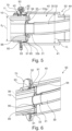
- FIG. 3 shows a sectional view of the fluid transport device 1 where the outer line component 40 is in the demounted state 60.
- the outer line component 40 has been moved in a first direction 63 relative to the first line connector 10 and relative to the inner line component 30.
- the outer line component 40 was moved to a first position 61 in which the first coupling end 31 of the inner line component 30 is uncovered and thus accessible to an operator from the outside.
- Fig. 4 also shows a sectional view of the fluid transport device 1 where the outer line component 40 is in the demounted state 60.
- the outer line component 40 has been moved in a second direction 64 relative to the second line connector 20 and relative to the inner line component 30.
- the outer line component 40 was moved to a second position 62 in which the second coupling end 32 of the inner line component 30 is uncovered and thus accessible to an operator from the outside.
- Fig. 3 further shows a coupling unit 33 that couples the first coupling end 31 of the inner line component 30 to the first line connector 10.
- the coupling unit 33 comprises a first coupling element 33a and a second coupling element 33b, each of which has overlapping features, for example recesses.
- the recesses of the first coupling element 33a are configured to engage corresponding recesses of the second coupling element 33b.
- Fig. 3 shows a configuration in which the coupling unit 33 attaches the first coupling end 31, for example via screws and/or bolts, to the first line connector 10.
- the coupling elements 33a, 33b may have a half-ring shape and together provide a full-ring shape. When mounted, the coupling unit 33 may comprise a disk-like or plate-like structure.
- Fig. 4 shows a further coupling unit 34 that couples the second coupling end 32 of the inner line component 30 to the second line connector 20.
- the further coupling unit 34 comprises a first coupling element 34a and a second coupling element 34b, each of which has overlapping features, for example recesses.
- the recesses of the first coupling element 34a are configured to engage corresponding recesses of the second coupling element 34b.
- Fig. 4 shows a configuration in which the further coupling unit 34 attaches the first coupling end 31, for example via screws and/or bolts, to the second line connector 20.
- the coupling elements 34a, 34b may have a half-ring shape and together provide a full-ring shape.
- the further coupling unit 34 may comprise a disk-like or plate-like structure.
- the coupling unit 33 of Fig. 3 can act as an inner pipe connection by means of which the inner line component 30, e.g., hose, is held in place via the split bolted flanges 33a, 33b with overlapping features.
- a face seal can be used in between the inner line component 30 and the first line connector 10 to prevent leakage from the inner fluid pipe which is constructed of the inner line component 30 and the first line connector 10.
- Fig. 3 further shows a primary seal component 91 which will be described in more detail with reference to Fig. 5 .
- the outer line component 40 is attached to the first line connector 10 via the first flange component 70 and attached to the second line connector 20 via the second flange component 80.
- the first flange component 70 is radially attached to an outer surface 11 of the first line connector 10 and axially attached to a first axial surface 42 of the outer line component 40.
- the second flange component 80 in contrast, is axially attached to an axial surface 21 of the second line connector 20 and axially attached to a second axial surface 43 of the outer line component 40.
- the first flange component 70 comprises two flange elements 71, 72, each of the two flange elements 71, 72 having a half-ring shape with an L-shaped cross-section.
- the two flange elements 71, 72 of the first flange component 70 together form a full-ring shape when the first flange component 70 is attached to the first line connector 10 as shown in Fig. 1 .
- the second flange component 80 comprises two flange elements 81, 82, each of the two flange elements 81, 82 having a half-ring shape with an H-shaped cross-section.
- the two flange elements 81, 82 of the second flange component 80 together form a full-ring shape when the second flange component 80 is attached to the second line connector 20 as shown in Fig. 1 .
- the half-shells 71, 72 of the first flange component 70 and the half-shells 81, 82 of the second flange component 80 can be designed with overlapping features, for example corresponding recesses, for better alignment during the installation.
- the outer line component 40 herein also referred to as sliding sleeve 40 or outer tube 40, is fixed in place by respective half-shells of the flange components 70, 80 so that it cannot move during operation of a vehicle in which the fluid transport device 1 is installed. Static seals can be used underneath the sliding sleeve 40.
- the half-shells are bolted onto the sliding sleeve 40 on one side and on the first and second line connectors 10, 20 on the other side.
- the shell bolted joint can be provided by using either an axial flange component as described for the second line connector 20 in Figs. 1 and 2 or by attaching the flange component radially around the circumference of the line connector as described for the first line connector 10 in Figs. 1 and 2 .
- the radial configuration allows the shell to be more axially compact.
- FIG. 5 shows a cross-sectional view of a portion of the fluid transport device 1 of Fig. 1 .
- This Figure shows the first line connector 10 which is fluidly connected to the first coupling end 31 of the inner line component 30 by means of the coupling unit 33, which coupling unit comprises the two coupling elements 33a and 33b. A part of the first coupling end 31 may be pressed against a face surface of the first line connector 10 by the coupling unit 33 which itself is attached to the first line connector 10 via bolts or screws.
- An inner seal component 95 is provided at the contact region between the first coupling end 31 and the first line connector 10.
- the inner seal component 95 is thus configured to seal the coupling between the first coupling end 31 of the inner line component 30 and the first line connector 10.
- a recess 96 is provided for accommodating the inner seal component 95.
- a primary seal component 91 can be arranged between the outer line component 40 and the first line connector 10 when the outer line component 40 is in the mounted state 50 as shown in Fig. 5 .
- This primary seal component 91 may be a static seal.
- the primary seal component 91 may be arranged within a recess 94 that is provided for at least partially accommodating the primary seal component 91.
- the recess 94 and the primary seal component 91 may extend around the circumference of the first line connector 10 and may be arranged such that the primary seal component 91 seals off a space 35 between the inner line component 30 and the outer line component 40.
- the primary seal component 91 is arranged between an outer surface of the first line connector 10 and an inner surface of the outer line component 40 to seal off the space 35 with respect to the environment outside of the outer line component 40.
- the recess 94 and the primary seal component 91 may extend around an inner circumference of the outer line component 40 and may be arranged such that the primary seal component 91 seals off the space 35 between the inner line component 30 and the outer line component 40.
- a secondary seal component 92 can be arranged within a receptacle 93 that is at least partially defined by the axial surface 43 of the outer line component 40 and the outer surface 11 of the first line connector 10 when the outer line component 40 is in the mounted state 50.
- the receptacle 93 for accommodating the secondary seal component 92 can be further defined and closed by attaching the first flange component 70 to the outer surface 11 of the first line connector 10 and the axial surface 43 of the outer line component 40.
- At least a first portion 41 of the outer line component 40 has an inner diameter d 1 that is greater than an outer diameter d 2 of the first line connector 10, such that, in the demounted state 60, said first portion 41 of the outer line component 40 is movable outside of and along the first line connector 10, i.e., the outer line component 40 can be slid over the first line connector 10.
- a step 44 can be present at the outer line component 40, wherein the step 44 decreases the inner diameter d 1 , thereby reducing the radial space between the inner line component 30 and the outer line component 40.
- Fig. 6 shows a perspective cross-sectional view of the portion of the fluid transport device 1 as illustrated in Fig. 5.
- Fig. 6 therefore shows another perspective of most of the components already discussed in view of Fig. 5 , to which it is referred.
- Fig. 6 also shows a bore 36 that extends through the first line connector 10 and through the coupling unit 33.
- This bore 36 may provide an interconnection between different shroud sections in which separate outer line components 40 as explained herein are located.
- several bores 36 that extend through the first line connector 10 and through the coupling unit 33 can be provided. Two of them can be seen in Fig. 6 .
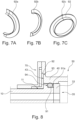
- Figs. 7A, 7B and 7C illustrate a gasket seal which may be used as the secondary seal component 92 described herein.
- Fig. 7A shows a first half 92a of the gasket seal 92
- Fig. 7B shows a second half 92b of the gasket seal 92b
- Fig. 7C shows the complete gasket seal 92 formed by the first and second halves 92a, 92b of the gasket seal 92.
- the gasket seal 92 can be manufactured as either two halves or as one piece with a cut 92c (see Fig. 7C ) to allow the installation around the first and second line connectors 10, 20.
- the gasket seal 92 can be made out of elastomer or PTFE.
- Figs. 8 and 9 show enlarged views of an arrangement of the primary seal component 91 and the secondary seal component 92 in the fluid transport device 1. Due to its shape, the primary seal component 91 would require seal stretching during the installation which might lead to the risk of installation damages and might also limit the application to stretchable seals.
- Figs. 8 and 9 now show two alternative groove designs, i.e., alternative designs for the receptacles 93 and 94.
- the receptacle 94 is open to space 35 and the outer diameter of the coupling unit 33 is enlarged to close the receptacle 94 after the primary seal component 91 is installed.
- a backup ring 91a may be provided between the primary seal component 91 and the coupling unit 33 in this configuration to prevent seal extrusion into the gaps between the first line connector 10 and the coupling unit 33.
- Fig. 9 the receptacle 94 is open with a small step 94a on the right end (at the exit) of the receptacle 94 to keep the primary seal component 91 in place.
- This configuration still requires stretching of the primary seal component 91 during the installation but the amount of stretch is much less and there is no need to use the coupling unit 33 as part of the receptacle 94.
- Both configurations of Figs. 8 and 9 allow for an easier installation and for the consideration of using seals that are less stretchable such as PTFE spring-energized seals or metal seals.
- seals for the primary seal component 91 and the secondary seal component 92 can be used. This includes but is not limited to an elastomer seal (e.g., O-ring, D-ring, square ring, X-ring), PTFE (or other polymer) spring energized seals, metal seals (O-ring, C-ring, spring-energized) and metal or polymer gaskets.
- elastomer seal e.g., O-ring, D-ring, square ring, X-ring
- PTFE or other polymer
- metal seals O-ring, C-ring, spring-energized
- metal or polymer gaskets metal or polymer gaskets.
- Fig. 10 shows an aircraft 100 comprising the fluid transport device 1 of Fig. 1 .
- the aircraft 100 may be a transport or passenger aircraft. It will be appreciated however that the fluid transport device 1 of Fig. 1 may be integrated into any kind of vehicle or even into a stationary platform.
- Fig. 11 shows a flow diagram of a method for assembling and disassembling a fluid transport device 1, for example the fluid transport device 1 of Fig. 1 as described above.
- a step S1 of the method comprises arranging a first line connector 10 spatially separated from a second line connector 20.
- a step S2 comprises arranging an inner line component 30 between the first line connector 10 and the second line connector 20.
- a step S3 comprises coupling a first coupling end 31 of the inner line component 30 to the first line connector 10 and a second coupling end 32 of the inner line component 30 to the second line connector 20, thereby fluidly connecting the first line connector 10 to the second line connector 20 via the inner line component 30.
- a step S4 comprises mounting an outer line component 40 to the first line connector 10 and to the second line connector 20, such that the outer line component 40 covers the first coupling end 31 of the inner line component 30 and the second coupling end 32 of the inner line component 30.
- a step S5 comprises demounting the outer line component 40 from the first line connector 10 and from the second line connector 20.
- a step S6 comprises moving the outer line component 40 relative to the inner line component 30 in order to uncover the first coupling end 31 of the inner line component 30 or the second coupling end 32 of the inner line component 30.
Landscapes
- Engineering & Computer Science (AREA)
- General Engineering & Computer Science (AREA)
- Mechanical Engineering (AREA)
- Aviation & Aerospace Engineering (AREA)
- Quick-Acting Or Multi-Walled Pipe Joints (AREA)
Abstract
Description
- The invention relates to double-walled fluid transportation systems. In particular, the invention relates to fluid transport device and method for assembling and disassembling a fluid transport device.
- Double-walled pipes are usually used on fuel-systems inside a vehicle, for example, inside a fuselage of an aircraft. The design of these double-walled pipes is mostly configured such that a connection of an inner pipe and a separated connection of an outer pipe is provided. In these configurations the outer pipe encloses the inner pipe. Different techniques have been developed to provide access to the connection areas where the inner pipe is connected to a surrounding line system. An access to the connection areas is important to enable the assembly and disassembly of the pipe connections, in particular the sealings provided at the pipe connections.
-
EP 3 957 894 A1 andGB 2 598 113 A - It may be seen as an object of the invention to provide a fluid transport device that allows using improved sealing arrangements.
- A system and a method according to the features of the independent claims are provided. Further embodiments of the invention are evident from the dependent claims and from the following description.
- According to an aspect of the invention, a fluid transport device is provided. The fluid transport device comprises a first line connector, a second line connector and an inner line component having a first coupling end and a second coupling end, wherein the first coupling end of the inner line component is configured to be coupled to the first line connector and the second coupling end of the inner line component is configured to be coupled to the second line connector, thereby fluidly connecting the first line connector to the second line connector via the inner line component. The fluid transport device further comprises an outer line component, herein also referred to as shroud or outer sleeve, wherein the outer line component is configured to adopt a mounted state, e.g., an assembled state, in which the outer line component is attached to the first line connector and to the second line connector, such that the outer line component covers, e.g., radially encloses, the first coupling end of the inner line component and the second coupling end of the inner line component. The outer line component is configured to adopt a demounted state, e.g., a disassembled state, in which the outer line component is detached from the first line connector and detached from the second line connector. In the demounted state, the outer line component is movable, for example slidable, relative to the inner line component in order to uncover the first coupling end of the inner line component or the second coupling end of the inner line component.
- The fluid transport device may be configured to transport a fluid, i.e., a liquid, a gas or a mixture thereof. In an example, the fluid transport device may transport a fuel, e.g., hydrogen, from a fuel storage such as a tank or fuel cell to a fuel consumer such as an engine, etc. The fluid transport device may be part of a vehicle, for example of an aircraft. In particular, the fluid transport device may be a part of a fuel supply system of an aircraft in which the fuel from the fuel storage or fuel cell is supplied to the engine(s) of the aircraft. The term "line" in the context of the present invention may be understood as a "pipe", a "conduit" or a similar component that is configured to transport the fluid therethrough.
- The inventive fluid transport device may enable a facilitated assembly and/or disassembly of a sealed double-walled line system that is suitable to transport or supply hydrogen. In particular, the configuration of the inventive fluid transport device provides a double-walled design which may be prescribed for certain fuel transportation systems. In this double-walled design, the inner line component and the outer line component provide separate walls, wherein the outer line component radially covers or radially encloses the inner line component. In particular, the outer line component radially surrounds the inner line component over the entire length of the inner line component such that the outer line component may be connected to the first line connector and the second line connector, both line connectors being coupled to the respective coupling ends of the inner line component. The first and second line connectors may herein also be referred to as first and second fittings.
- An additional seal component may be provided for the connection between the outer line component and the first line connector as well as between the outer line component and the second line connector, such that the inner line component can be sealed with respect to the environment present outside of the outer line component and outside of the first and second line connectors. In other words, the inner line component is a line or pipe section that is sealed off from the environment. Due to the specific arrangement of the individual components, which will be described in more detail herein, a static seal can be used to seal the inner line component including the couplings to the first and second line connectors. Such a static seal has advantages when compared to a dynamic seal. Although dynamic seals can also be used in the context of the present invention, static seals may be preferred.
- Concerning leakage rates, a static seal may have advantages over a dynamic seal. This may be due to a compromise that must be made in the seal design to reduce the friction force and the risks of twisting or local surface deformation when the seal experiences movements. Furthermore, the seal wears and its performance degrades over time due to the regular motions. For fuel and fuel vapor, a dynamic seal might be sufficient, but for hydrogen it may be preferred to use a static seal, especially for the high pressure which may be needed for a direct-burn.
- Therefore, the inventive fluid transport device allows the introduction of high-performance seals on a double-walled pipe connection used for hydrogen applications. In addition, a reduced leak rate can be achieved because static seals can be used with this specific configuration. Also because of the static nature of the seal, performance degradation over time can be minimized. A further advantage is that a wider choice of sealing types and materials with better performance is available. With the inventive design of the fluid transport device, a secondary sealing component, e.g., a gasket, can also be used to further improve the sealing performance and reliability. The proposed sealing arrangements may allow simpler installation and lower risks of installation damages.
- The first line connector may provide a coupling component that fluidly couples the inner line component with a surrounding line system, e.g., the above-mentioned fuel supply system. That is, fluid that passes through the inner line component can be transferred through the first line connector and further into the fuel supply system. Accordingly, the second line connector may also provide a coupling component that fluidly couples the inner line component with a surrounding line system, e.g., the above-mentioned fuel supply system. That is, fluid that is transferred through the first line connector, for example from a fuel supply line, can be further transferred into the inner line component. The first line connector, the second line connector and the inner line component may thus directly transport the fluid. All these three components may have a circular cross-section or a tube-like structure. For example, each of the three components may have the shape of a pipe.
- In an example, the inner line component may be a longitudinal pipe or hose that extends from between the first line connector and the second line connector. Similar, the outer line component may be a longitudinal pipe or tube-like structure enclosing the longitudinal inner line component. In the demounted state, the outer line component may thus be slid along a longitudinal direction of the inner line component to uncover either the first coupling end or the second coupling end of the inner line component.
- The outer line component may not directly transport the fluid, but rather provides an outer wall or sleeve that radially encloses the inner line component, and preferably also a portion of the first line connector and the second line connector. This configuration provides a double-wall design. By enclosing the inner line component and the first and second coupling ends of the inner line components, the outer line component covers or houses the complete inner line component in the mounted state, such that an operator acting from the outside of the device has no access to the inner line component and the connections between the inner line component to first and second line connectors.
- However, in the demounted state, such an access by an operator from the outside of the device may be provided, in particular, when the outer line component is moved or slid along the inner line component to expose, i.e., to uncover, either the first coupling end of the inner line component or the second coupling end of the inner line component.
- According to an embodiment, in the demounted state, the outer line component is movable to a first position in which the first coupling end of the inner line component is uncovered while the second coupling end of the inner line component is still covered by the outer line component. Alternatively, in the demounted state, the outer line component is movable to a second position in which the first coupling end of the inner line component is still covered by the outer line component while the second coupling end of the inner line component is uncovered.
- For example, when moving the outer line component in a first direction along and/or parallel to the inner line component, the first coupling end of the inner line component will be uncovered, i.e., exposed to the environment, while the second coupling end of the inner line component will be still covered, i.e., enclosed, by the outer line component. In the alternative, when moving the outer line component in a second direction along and/or parallel to the inner line component, the second coupling end of the inner line component will be uncovered, i.e., exposed to the environment, while the first coupling end of the inner line component will still be covered, i.e., enclosed, by the outer line component. The first direction may be opposite to the second direction. In the uncovered or exposed state, the respective coupling end may be freely accessible from the outside, for example by an operator, for assembling, disassembling or servicing the coupling between the respective coupling end of the inner line component and the associated line connector that is coupled to said respective coupling end.
- According to an embodiment, at least a first portion of the outer line component has an inner diameter that is greater than an outer diameter of the first line connector, such that, in the demounted state, said first portion of the outer line component is movable outside of and along the first line connector.
- For mounting the outer line component to the first line connector, the outer line component may be slid over a small mounting portion of the first line connector. Therefore, the inner diameter of the first portion of the outer line component may be greater than this small mounting portion of the first line connector in order to enable sliding of at least the first portion of the outer line component over the small mounting portion of the first line connector before connecting the outer line component to the first line connector. In this manner, an overlap in the mounted state can be provided between an inner surface of the outer line component and an outer surface of the first line connector, thereby enabling the placement of one or more seal components, as will be described in more detail below.
- According to an embodiment, in the mounted state, the outer line component encloses the inner line component at least over the entire length of the inner line component.
- In this manner, the inner line component can be completely enclosed and covered by the outer line component. By sealingly engaging the outer line component with the first and second line connectors, the inner line component can be hermetically sealed off from the environment.
- According to an embodiment, in the mounted state, the outer line component is radially spaced apart from the inner line component.
- This means that there may be a space between an outer surface of the inner line component and an inner surface of the outer line component. The space may be chosen such that during movement of the outer line component relative to the inner line component, a contact between both components can be avoided. As indicated above, the inner line component may be a hose that has a certain flexibility and, thus, may slightly move inside the outer line component.
- According to an embodiment, in the mounted state, the outer line component is attached to the first line connector via a first flange component and attached to the second line connector via a second flange component.
- The attachment between the outer line component and the first flange component may be provided by a bolted or screwed joint. The attachment between the first flange component and the first line connector may also be provided by a bolted or screwed joint. There may not be any direct joints between the outer line component and the first line connector. However, a primary sealing component may be arranged between the outer line component and the first line connector.
- Analogously, the attachment between the outer line component and the second flange component may be provided by a bolted or screwed joint. The attachment between the second flange component and the second line connector may also be provided by a bolted or screwed joint. There may not be any direct joints between the outer line component and the second line connector. However, another primary sealing component may be arranged between the outer line component and the second line connector.
- According to an embodiment, the first flange component is radially attached to the first line connector and axially attached to the outer line component. Additionally or alternatively, the second flange component is axially attached to the second line connector and axially attached to the outer line component.
- For example, the first flange may be provided in the form of an L-flange, where the first flange leg is radially attached via a bolted or screwed joint to the outer surface of the first line connector and the second flange leg is axially attached via a bolted or screwed joint to a corresponding flange element of the outer line component.
- For example, the second flange may be provided in the form of an H-flange, where the first flange leg is axially attached via a bolted or screwed joint to a corresponding flange element of the second line connector and the second flange leg is axially attached via a bolted or screwed joint a further corresponding flange element of the outer line component.
- According to an embodiment, the first flange component comprises two flange elements, each of the two flange elements having a half-ring shape, wherein the two flange elements of the first flange component together form a full-ring shape when the first flange component is attached to the first line connector. Alternatively or additionally, the second flange component comprises two flange elements, each of the two flange elements having a half-ring shape, wherein the two flange elements of the second flange component together form a full-ring shape when the second flange component is attached to the second line connector. The two flange elements of the first and second flange components may herein also be referred to as half shells.
- For example, in the mounted state of the outer line component, the two flange elements, i.e., the half shells, of the first flange component are attached to the first line connector. In this mounted state, the first flange component shows the full-ring shape, thereby completely encircling the first line connector. It may be possible, that the flange component can be split into the two flange elements, each having a half-ring shape, only when the first flange component is detached from the first line connector.
- Each two flange elements of half-ring shape may have two connecting regions with respective overlapping features. An overlapping feature of one flange element may be in the form of a recess that engages a corresponding overlapping feature of the counterpart flange element. This will be described in more detail with regard to the description of the figures below. The above explanations with regard to the first flange component and its connecting features may analogously apply for the second flange component.
- According to an embodiment, the fluid transport device further comprises a primary seal component arranged between the outer line component and the first line connector when the outer line component is in the mounted state.
- The primary seal component may comprise a seal that is located within a closed groove underneath the outer line component, i.e., underneath the sliding sleeve. Several possibilities for the seal geometry, for example O-ring, square ring, X-ring etc., can be used and Fluorosilicone, Butyl etc. can be used as material for the seal. The primary seal component is arranged between the outer line component and the first line connector, thereby sealing off the inner line component as well as the space between the inner line component and outer line component from the environment.
- According to an embodiment, primary seal component comprises a static seal.
- A static seal may be a seal that seals components with respect to each other, which after the assembly or mounting process do not move relative to each other. However, as indicated above, a dynamic seal can also be used.
- According to an embodiment, the fluid transport device further comprises a secondary seal component arranged within a receptacle that is at least partially defined by an axial surface of the outer line component and an outer surface of the first line connector when the outer line component is in the mounted state.
- In an example, the receptacle is defined by the axial surface of the outer line component, the outer surface of the first line connector and the first flange component. The secondary seal component may have an L-shape. Accordingly, the receptacle may have an L-shape to accommodate the secondary seal component. The secondary seal component may comprise a seal in the form of a gasket underneath the two flange elements, i.e., the two half shells, of the first flange component to improve the sealing performance and reliability. This gasket can be manufactured as either two halves or as one piece with a cut to allow an installation around the first and second line connectors, i.e., around the fittings. There may be overlapping features provided on the gasket to minimize leakage at the segment interface or through the cut. The gasket can be made of elastomer or PTFE.
- According to an embodiment, the fluid transport device further comprises an inner seal component configured to seal a coupling between the first coupling end of the inner line component and the first line connector.
- The inner seal component therefore prevents leakage of the fluid that passes the coupling between the inner line component and the first line connector such that no fluid can leak into the space between the inner line component and the outer line component. Analogously, another inner seal component may be provided to seal a coupling between the second coupling end of the inner line component and the second line connector.
- According to an aspect, the fluid transport device as described herein is used for transporting hydrogen.
- According to another aspect, an aircraft is provided that comprises the fluid transport as described herein.
- According to another aspect, a method for assembling and disassembling a fluid transport device is provided. In a step of the method, a first line connector is arranged spatially separated from a second line connector. In another step, an inner line component is arranged between the first line connector and the second line connector. In another step, a first coupling end of the inner line component is coupled to the first line connector and a second coupling end of the inner line component is coupled to the second line connector, thereby fluidly connecting the first line connector to the second line connector via the inner line component. In another step, an outer line component is mounted to the first line connector and to the second line connector, such that the outer line component covers the first coupling end of the inner line component and the second coupling end of the inner line component. In another step, the outer line component is demounted from the first line connector and from the second line connector. In another step, the outer line component is moved relative to the inner line component in order to uncover the first coupling end of the inner line component or the second coupling end of the inner line component.
- The above-mentioned steps of the method may be performed in the indicated order.
- The inventive fluid transport device as described above and below is designed with a sliding sleeve, i.e., the outer line component, to allow the installation of the inner coupling(s) via bolted flange components. An additional mechanism is integrated to fix the sliding sleeve after the installation and this allows the use of high performance static seals on the inner and outer line components. Furthermore, the inventive fluid transport device provides several sealing concepts that can be used in combination with the coupling design.
- The present invention will hereinafter be described in conjunction with the following drawing figures, wherein like numerals denote like elements, and wherein:
- Fig. 1
- shows a fluid transport device in an assembled state.
- Fig. 2
- shows the fluid transport device of
Fig. 1 in a partially disassembled state. - Fig. 3
- shows the fluid transport device of
Fig. 1 with a first coupling end being uncovered. - Fig. 4
- shows the fluid transport device of
Fig. 1 with a second coupling end being uncovered. - Fig. 5
- shows a cross-sectional view of a portion of the fluid transport device of
Fig. 1 . - Fig. 6
- shows a perspective cross-sectional view of a portion of the fluid transport device of
Fig. 1 . - Fig. 7A
- shows a first half of a gasket seal.
- Fig. 7B
- shows a second half of a gasket seal.
- Fig. 7C
- shows a complete gasket seal.
- Fig. 8
- shows an arrangement of a primary seal component and a secondary seal component in the fluid transport device of
Fig. 1 . - Fig. 9
- shows an alternative design for a primary seal component in the fluid transport device of
Fig. 1 . - Fig. 10
- shows an aircraft comprising the fluid transport device of
Fig. 1 . - Fig. 11
- shows a flow diagram of a method for assembling and disassembling a fluid transport device.
- The representations and illustrations in the drawings are schematic and not to scale. A better understanding of the method and system described above may be obtained through a review of the illustrations accompanying this application together with a review of the detailed description that follows.
-
Fig. 1 shows afluid transport device 1 in an assembled state, i.e., in a mounted state, where anouter line component 40 is mounted to afirst line connector 10 via aflange component 70 as well as to a second line connector (not visible inFig. 1 ) via asecond flange component 80. An inner line component, which in the mounted state is completely covered by theouter line component 40 and therefore not visible inFig. 1 has a first coupling end and a second coupling end, wherein the first coupling end couples the (covered) inner line component to thefirst line connector 10 and the second coupling end couples the inner line component (covered) to the second line connector. In the illustrated example, a cut is drawn through theouter line component 40 indicating that the outer line component can have any length. - The
outer line component 40 is configured to adopt the mountedstate 50 as shown inFig. 1 in which theouter line component 40 is attached to thefirst line connector 10 and to the second line connector, such that theouter line component 40 covers the first coupling end and the second coupling end of the inner line component. - The
outer line component 40 is further configured to adopt ademounted state 60 as shown inFig. 2 in which theouter line component 40 is detached from thefirst line connector 10 and also detached from thesecond line connector 20. In thisdemounted state 60, theouter line component 40 is movable relative to the inner line component in order to uncover the first coupling end of the inner line component or the second coupling end of the inner line component. The inner line component and one of its coupling ends will be discussed in more detail with respect toFig. 5 below. - As can bee seen from
Figs. 1 and 2 , theouter line component 40 as well as thefirst line connector 10 and thesecond line connector 20 appear in the form of pipe segments, pipe-like structures or tube-like structures. Thefirst line connector 10 and thesecond line connector 20 may be fluidly coupled via the inner line component such that fluid can flow through these components. Theouter line component 40, however, may not be in contact with any of the passing fluid. Theouter line component 40 may rather be a shroud or sliding sleeve that can be moved or slid relative to the inner line component as well as thefirst line connector 10 and thesecond line connector 20, when theouter line component 40 is in thedemounted state 60 as shown inFig. 2 . - As can be derived from
Fig. 2 , theouter line component 40, i.e., the slidingsleeve 40 orouter tube 40, can now be slid to the left or right side as indicated byarrow 65 in order to allow access to the connection areas of the inner line component. - For example,
Fig. 3 shows a sectional view of thefluid transport device 1 where theouter line component 40 is in thedemounted state 60. Theouter line component 40 has been moved in afirst direction 63 relative to thefirst line connector 10 and relative to theinner line component 30. In this configuration, theouter line component 40 was moved to a first position 61 in which thefirst coupling end 31 of theinner line component 30 is uncovered and thus accessible to an operator from the outside. -
Fig. 4 also shows a sectional view of thefluid transport device 1 where theouter line component 40 is in thedemounted state 60. Theouter line component 40 has been moved in asecond direction 64 relative to thesecond line connector 20 and relative to theinner line component 30. In this configuration, theouter line component 40 was moved to a second position 62 in which thesecond coupling end 32 of theinner line component 30 is uncovered and thus accessible to an operator from the outside. - Although not shown in
Figs. 3 and 4 , it is possible that, in the first position 61, thesecond coupling end 32 is covered by theouter line component 40, and that, in the second position 62, thefirst coupling end 31 is covered by theouter line component 40. -
Fig. 3 further shows acoupling unit 33 that couples thefirst coupling end 31 of theinner line component 30 to thefirst line connector 10. Thecoupling unit 33 comprises afirst coupling element 33a and asecond coupling element 33b, each of which has overlapping features, for example recesses. For example, the recesses of thefirst coupling element 33a are configured to engage corresponding recesses of thesecond coupling element 33b.Fig. 3 shows a configuration in which thecoupling unit 33 attaches thefirst coupling end 31, for example via screws and/or bolts, to thefirst line connector 10. Thecoupling elements coupling unit 33 may comprise a disk-like or plate-like structure. -
Fig. 4 shows afurther coupling unit 34 that couples thesecond coupling end 32 of theinner line component 30 to thesecond line connector 20. Thefurther coupling unit 34 comprises afirst coupling element 34a and asecond coupling element 34b, each of which has overlapping features, for example recesses. For example, the recesses of thefirst coupling element 34a are configured to engage corresponding recesses of thesecond coupling element 34b.Fig. 4 shows a configuration in which thefurther coupling unit 34 attaches thefirst coupling end 31, for example via screws and/or bolts, to thesecond line connector 20. Thecoupling elements further coupling unit 34 may comprise a disk-like or plate-like structure. - The
coupling unit 33 ofFig. 3 can act as an inner pipe connection by means of which theinner line component 30, e.g., hose, is held in place via the split boltedflanges inner line component 30 and thefirst line connector 10 to prevent leakage from the inner fluid pipe which is constructed of theinner line component 30 and thefirst line connector 10. -
Fig. 3 further shows aprimary seal component 91 which will be described in more detail with reference toFig. 5 . - As shown in
Figs. 1 and 2 , theouter line component 40 is attached to thefirst line connector 10 via thefirst flange component 70 and attached to thesecond line connector 20 via thesecond flange component 80. Thefirst flange component 70 is radially attached to anouter surface 11 of thefirst line connector 10 and axially attached to a firstaxial surface 42 of theouter line component 40. Thesecond flange component 80, in contrast, is axially attached to anaxial surface 21 of thesecond line connector 20 and axially attached to a secondaxial surface 43 of theouter line component 40. - As can be seen in
Fig. 2 , thefirst flange component 70 comprises twoflange elements flange elements flange elements first flange component 70 together form a full-ring shape when thefirst flange component 70 is attached to thefirst line connector 10 as shown inFig. 1 . - As can also be seen in
Fig. 2 , thesecond flange component 80 comprises twoflange elements flange elements flange elements second flange component 80 together form a full-ring shape when thesecond flange component 80 is attached to thesecond line connector 20 as shown inFig. 1 . - The half-
shells first flange component 70 and the half-shells second flange component 80 can be designed with overlapping features, for example corresponding recesses, for better alignment during the installation. - This above-described
fluid transport device 1 allows to combine a double-walled coupling design with high performance seals for high pressure hydrogen applications. Theouter line component 40, herein also referred to as slidingsleeve 40 orouter tube 40, is fixed in place by respective half-shells of theflange components fluid transport device 1 is installed. Static seals can be used underneath the slidingsleeve 40. In this design, the half-shells are bolted onto the slidingsleeve 40 on one side and on the first andsecond line connectors second line connector 20 inFigs. 1 and 2 or by attaching the flange component radially around the circumference of the line connector as described for thefirst line connector 10 inFigs. 1 and 2 . The radial configuration allows the shell to be more axially compact. -
Fig. 5 shows a cross-sectional view of a portion of thefluid transport device 1 ofFig. 1 . This Figure shows thefirst line connector 10 which is fluidly connected to thefirst coupling end 31 of theinner line component 30 by means of thecoupling unit 33, which coupling unit comprises the twocoupling elements first coupling end 31 may be pressed against a face surface of thefirst line connector 10 by thecoupling unit 33 which itself is attached to thefirst line connector 10 via bolts or screws. - An
inner seal component 95 is provided at the contact region between thefirst coupling end 31 and thefirst line connector 10. Theinner seal component 95 is thus configured to seal the coupling between thefirst coupling end 31 of theinner line component 30 and thefirst line connector 10. Arecess 96 is provided for accommodating theinner seal component 95. - Furthermore, a
primary seal component 91 can be arranged between theouter line component 40 and thefirst line connector 10 when theouter line component 40 is in the mountedstate 50 as shown inFig. 5 . Thisprimary seal component 91 may be a static seal. Theprimary seal component 91 may be arranged within arecess 94 that is provided for at least partially accommodating theprimary seal component 91. Therecess 94 and theprimary seal component 91 may extend around the circumference of thefirst line connector 10 and may be arranged such that theprimary seal component 91 seals off aspace 35 between theinner line component 30 and theouter line component 40. In particular, theprimary seal component 91 is arranged between an outer surface of thefirst line connector 10 and an inner surface of theouter line component 40 to seal off thespace 35 with respect to the environment outside of theouter line component 40. In an alternative example, which is not shown in the Figures, therecess 94 and theprimary seal component 91 may extend around an inner circumference of theouter line component 40 and may be arranged such that theprimary seal component 91 seals off thespace 35 between theinner line component 30 and theouter line component 40. - Furthermore, as can also be derived from
Fig. 5 in connection withFigs. 8 and9 , asecondary seal component 92 can be arranged within areceptacle 93 that is at least partially defined by theaxial surface 43 of theouter line component 40 and theouter surface 11 of thefirst line connector 10 when theouter line component 40 is in the mountedstate 50. Thereceptacle 93 for accommodating thesecondary seal component 92 can be further defined and closed by attaching thefirst flange component 70 to theouter surface 11 of thefirst line connector 10 and theaxial surface 43 of theouter line component 40. - As can be derived from
Fig. 5 . at least afirst portion 41 of theouter line component 40 has an inner diameter d1 that is greater than an outer diameter d2 of thefirst line connector 10, such that, in thedemounted state 60, saidfirst portion 41 of theouter line component 40 is movable outside of and along thefirst line connector 10, i.e., theouter line component 40 can be slid over thefirst line connector 10. Astep 44 can be present at theouter line component 40, wherein thestep 44 decreases the inner diameter d1, thereby reducing the radial space between theinner line component 30 and theouter line component 40. -
Fig. 6 shows a perspective cross-sectional view of the portion of thefluid transport device 1 as illustrated inFig. 5. Fig. 6 therefore shows another perspective of most of the components already discussed in view ofFig. 5 , to which it is referred.Fig. 6 also shows abore 36 that extends through thefirst line connector 10 and through thecoupling unit 33. This bore 36 may provide an interconnection between different shroud sections in which separateouter line components 40 as explained herein are located. In an example,several bores 36 that extend through thefirst line connector 10 and through thecoupling unit 33 can be provided. Two of them can be seen inFig. 6 . -
Figs. 7A, 7B and 7C illustrate a gasket seal which may be used as thesecondary seal component 92 described herein. In particular,Fig. 7A shows afirst half 92a of thegasket seal 92,Fig. 7B shows asecond half 92b of thegasket seal 92b andFig. 7C shows thecomplete gasket seal 92 formed by the first andsecond halves gasket seal 92. These Figures illustrate that thegasket seal 92 can be manufactured as either two halves or as one piece with acut 92c (seeFig. 7C ) to allow the installation around the first andsecond line connectors gasket seal 92 to minimize any potential leakage at the segment interface or through thecut 92c. Thegasket seal 92 can be made out of elastomer or PTFE. -
Figs. 8 and9 show enlarged views of an arrangement of theprimary seal component 91 and thesecondary seal component 92 in thefluid transport device 1. Due to its shape, theprimary seal component 91 would require seal stretching during the installation which might lead to the risk of installation damages and might also limit the application to stretchable seals.Figs. 8 and9 now show two alternative groove designs, i.e., alternative designs for thereceptacles - In
Fig. 8 , thereceptacle 94 is open tospace 35 and the outer diameter of thecoupling unit 33 is enlarged to close thereceptacle 94 after theprimary seal component 91 is installed. Abackup ring 91a may be provided between theprimary seal component 91 and thecoupling unit 33 in this configuration to prevent seal extrusion into the gaps between thefirst line connector 10 and thecoupling unit 33. - In
Fig. 9 , thereceptacle 94 is open with asmall step 94a on the right end (at the exit) of thereceptacle 94 to keep theprimary seal component 91 in place. This configuration still requires stretching of theprimary seal component 91 during the installation but the amount of stretch is much less and there is no need to use thecoupling unit 33 as part of thereceptacle 94. Both configurations ofFigs. 8 and9 allow for an easier installation and for the consideration of using seals that are less stretchable such as PTFE spring-energized seals or metal seals. - It is noted that different types of seals for the
primary seal component 91 and thesecondary seal component 92 can be used. This includes but is not limited to an elastomer seal (e.g., O-ring, D-ring, square ring, X-ring), PTFE (or other polymer) spring energized seals, metal seals (O-ring, C-ring, spring-energized) and metal or polymer gaskets. -
Fig. 10 shows anaircraft 100 comprising thefluid transport device 1 ofFig. 1 . Theaircraft 100 may be a transport or passenger aircraft. It will be appreciated however that thefluid transport device 1 ofFig. 1 may be integrated into any kind of vehicle or even into a stationary platform. -
Fig. 11 shows a flow diagram of a method for assembling and disassembling afluid transport device 1, for example thefluid transport device 1 ofFig. 1 as described above. - A step S1 of the method comprises arranging a
first line connector 10 spatially separated from asecond line connector 20. A step S2 comprises arranging aninner line component 30 between thefirst line connector 10 and thesecond line connector 20. A step S3 comprises coupling afirst coupling end 31 of theinner line component 30 to thefirst line connector 10 and asecond coupling end 32 of theinner line component 30 to thesecond line connector 20, thereby fluidly connecting thefirst line connector 10 to thesecond line connector 20 via theinner line component 30. A step S4 comprises mounting anouter line component 40 to thefirst line connector 10 and to thesecond line connector 20, such that theouter line component 40 covers thefirst coupling end 31 of theinner line component 30 and thesecond coupling end 32 of theinner line component 30. A step S5 comprises demounting theouter line component 40 from thefirst line connector 10 and from thesecond line connector 20. A step S6 comprises moving theouter line component 40 relative to theinner line component 30 in order to uncover thefirst coupling end 31 of theinner line component 30 or thesecond coupling end 32 of theinner line component 30.
Claims (15)
- Fluid transport device (1), comprising:a first line connector (10);a second line connector (20);an inner line component (30) having a first coupling end (31) and a second coupling end (32), wherein the first coupling end (31) of the inner line component (30) is configured to be coupled to the first line connector (10) and the second coupling end (32) of the inner line component (30) is configured to be coupled to the second line connector (20), thereby fluidly connecting the first line connector (10) to the second line connector (20) via the inner line component (30);an outer line component (40);wherein the outer line component (40) is configured to adopt a mounted state (50) in which the outer line component (40) is attached to the first line connector (10) and to the second line connector (20), such that the outer line component (40) covers the first coupling end (31) of the inner line component (30) and the second coupling end (32) of the inner line component (30);wherein the outer line component (40) is configured to adopt a demounted state (60) in which the outer line component (40) is detached from the first line connector (10) and detached from the second line connector (20);wherein, in the demounted state (60), the outer line component (40) is movable relative to the inner line component (30) in order to uncover the first coupling end (31) of the inner line component (30) or the second coupling end (32) of the inner line component (30).
- Fluid transport device (1) according to claim 1,wherein, in the demounted state (60), the outer line component (40) is movable to a first position (61) in which the first coupling end (31) of the inner line component (30) is uncovered and the second coupling end (32) of the inner line component (30) is covered by the outer line component (40); orwherein, in the demounted state (60), the outer line component (40) is movable to a second position (62) in which the first coupling end (31) of the inner line component (30) is covered by the outer line component (40) and the second coupling end (32) of the inner line component (30) is uncovered.
- Fluid transport device (1) according to any one of the preceding claims,
wherein at least a first portion (41) of the outer line component (40) has an inner diameter (di) that is greater than an outer diameter (d2) of the first line connector (10), such that, in the demounted state (60), said first portion (41) of the outer line component (40) is movable outside of and along the first line connector (10). - Fluid transport device (1) according to any one of the preceding claims,
wherein, in the mounted state (50), the outer line component (40) encloses the inner line component (30) at least over the entire length of the inner line component (30). - Fluid transport device (1) according to any one of the preceding claims,
wherein, in the mounted state (50), the outer line component (40) is radially spaced apart from the inner line component (30). - Fluid transport device (1) according to any one of the preceding claims,
wherein, in the mounted state (50), the outer line component (40) is attached to the first line connector (10) via a first flange component (70) and attached to the second line connector (20) via a second flange component (80). - Fluid transport device (1) according to claim 6,wherein the first flange component (70) is radially attached to the first line connector (10) and axially attached to the outer line component (40); and/orwherein the second flange component (80) is axially attached to the second line connector (20) and axially attached to the outer line component (40).
- Fluid transport device (1) according to any one of claims 6 or 7,wherein the first flange component (70) comprises two flange elements (71, 72), each of the two flange elements (71, 72) having a half-ring shape, wherein the two flange elements (71, 72) of the first flange component (70) together form a full-ring shape when the first flange component (70) is attached to the first line connector (10); and/orwherein the second flange component (80) comprises two flange elements (81, 82), each of the two flange elements (81, 82) having a half-ring shape, wherein the two flange elements (81, 82) of the second flange component (80) together form a full-ring shape when the second flange component (80) is attached to the second line connector (20).
- Fluid transport device (1) according to any one of the preceding claims, further comprising:
a primary seal component (91) arranged between the outer line component (40) and the first line connector (10) when the outer line component (40) is in the mounted state (50). - Fluid transport device (1) according to any one of the preceding claims,
wherein the primary seal component (91) comprises a static seal. - Fluid transport device (1) according to any one of the preceding claims, further comprising:
a secondary seal component (92) arranged within a receptacle (93) that is at least partially defined by an axial surface (43) of the outer line component (40) and an outer surface (11) of the first line connector (10) when the outer line component (40) is in the mounted state (50). - Fluid transport device (1) according to any one of the preceding claims, further comprising:
an inner seal component (95) configured to seal a coupling between the first coupling end (31) of the inner line component (30) and the first line connector (10). - Use of a fluid transport device (1) according to any one of the preceding claims for transporting hydrogen.
- Aircraft (100) comprising a fluid transport device (1) according to any one of claims 1 to 12.
- Method for assembling and disassembling a fluid transport device (1), comprising:arranging a first line connector (10) spatially separated from a second line connector (20, SI);arranging an inner line component (30) between the first line connector (10) and the second line connector (20, S2);coupling a first coupling end (31) of the inner line component (30) to the first line connector (10) and a second coupling end (32) of the inner line component (30) to the second line connector (20), thereby fluidly connecting the first line connector (10) to the second line connector (20) via the inner line component (30, S3);mounting an outer line component (40) to the first line connector (10) and to the second line connector (20), such that the outer line component (40) covers the first coupling end (31) of the inner line component (30) and the second coupling end (32) of the inner line component (30, S4);demounting the outer line component (40) from the first line connector (10) and from the second line connector (20, S5),moving the outer line component (40) relative to the inner line component (30) in order to uncover the first coupling end (31) of the inner line component (30) or the second coupling end (32) of the inner line component (30, S6).
Priority Applications (3)
| Application Number | Priority Date | Filing Date | Title |
|---|---|---|---|
| EP22191249.6A EP4325107B1 (en) | 2022-08-19 | 2022-08-19 | Fluid transport device and method for assembling and disassembling a fluid transport device |
| CN202311034214.6A CN117588625A (en) | 2022-08-19 | 2023-08-16 | Fluid delivery device and methods for assembling and disassembling fluid delivery device |
| US18/235,202 US12366317B2 (en) | 2022-08-19 | 2023-08-17 | Fluid transport device and method for assembling and disassembling a fluid transport device |
Applications Claiming Priority (1)
| Application Number | Priority Date | Filing Date | Title |
|---|---|---|---|
| EP22191249.6A EP4325107B1 (en) | 2022-08-19 | 2022-08-19 | Fluid transport device and method for assembling and disassembling a fluid transport device |
Publications (2)
| Publication Number | Publication Date |
|---|---|
| EP4325107A1 true EP4325107A1 (en) | 2024-02-21 |
| EP4325107B1 EP4325107B1 (en) | 2025-03-05 |
Family
ID=83004898
Family Applications (1)
| Application Number | Title | Priority Date | Filing Date |
|---|---|---|---|
| EP22191249.6A Active EP4325107B1 (en) | 2022-08-19 | 2022-08-19 | Fluid transport device and method for assembling and disassembling a fluid transport device |
Country Status (3)
| Country | Link |
|---|---|
| US (1) | US12366317B2 (en) |
| EP (1) | EP4325107B1 (en) |
| CN (1) | CN117588625A (en) |
Citations (6)
| Publication number | Priority date | Publication date | Assignee | Title |
|---|---|---|---|---|
| GB2102524A (en) * | 1981-07-29 | 1983-02-02 | United Technologies Corp | Tube coupling |
| WO2011007100A2 (en) * | 2009-07-16 | 2011-01-20 | Airbus Operations (S.A.S) | Device for protecting piping from lightning |
| US20110031745A1 (en) * | 2008-04-22 | 2011-02-10 | Fujikin Incorporated | Fluid coupling and retainer for fluid coupling |
| FR2978521A1 (en) * | 2011-07-29 | 2013-02-01 | Airbus Operations Sas | Device for fluid-tight connection of two pipes utilized for conveying fuel from reservoir located in wing to engine of aircraft, has intermediate pipe mounted in fluid-tight seal on inner tubular surface of eccentric sleeve |
| GB2598113A (en) | 2020-08-18 | 2022-02-23 | Agilent Technologies Inc | Fluidically coupling with elastic structure deformable by sealing element |
| EP3957894A1 (en) | 2020-08-18 | 2022-02-23 | Airbus Operations Limited | Fuel pipe assembly |
Family Cites Families (5)
| Publication number | Priority date | Publication date | Assignee | Title |
|---|---|---|---|---|
| US5141256A (en) * | 1991-06-26 | 1992-08-25 | Double Containment Systems | Double containment pipe assembly access housing |
| US5433484A (en) * | 1993-11-15 | 1995-07-18 | Enfield Industrial Corporation | Double containment pipe and fitting joint |
| US7427084B1 (en) * | 2006-06-09 | 2008-09-23 | Betz James C | Hose-in-hose coupler with longitudinally shiftable sleeve |
| FR2977299B1 (en) * | 2011-07-01 | 2014-11-07 | Airbus Operations Sas | DOUBLE SKIN TUBING SYSTEM, JOINT SYSTEM BETWEEN TWO TUBE PORTIONS, AND AIRCRAFT PROVIDED WITH SUCH A SYSTEM |
| GB2607958A (en) * | 2021-06-18 | 2022-12-21 | Airbus Operations Ltd | Pipe joint |
-
2022
- 2022-08-19 EP EP22191249.6A patent/EP4325107B1/en active Active
-
2023
- 2023-08-16 CN CN202311034214.6A patent/CN117588625A/en active Pending
- 2023-08-17 US US18/235,202 patent/US12366317B2/en active Active
Patent Citations (6)
| Publication number | Priority date | Publication date | Assignee | Title |
|---|---|---|---|---|
| GB2102524A (en) * | 1981-07-29 | 1983-02-02 | United Technologies Corp | Tube coupling |
| US20110031745A1 (en) * | 2008-04-22 | 2011-02-10 | Fujikin Incorporated | Fluid coupling and retainer for fluid coupling |
| WO2011007100A2 (en) * | 2009-07-16 | 2011-01-20 | Airbus Operations (S.A.S) | Device for protecting piping from lightning |
| FR2978521A1 (en) * | 2011-07-29 | 2013-02-01 | Airbus Operations Sas | Device for fluid-tight connection of two pipes utilized for conveying fuel from reservoir located in wing to engine of aircraft, has intermediate pipe mounted in fluid-tight seal on inner tubular surface of eccentric sleeve |
| GB2598113A (en) | 2020-08-18 | 2022-02-23 | Agilent Technologies Inc | Fluidically coupling with elastic structure deformable by sealing element |
| EP3957894A1 (en) | 2020-08-18 | 2022-02-23 | Airbus Operations Limited | Fuel pipe assembly |
Also Published As
| Publication number | Publication date |
|---|---|
| EP4325107B1 (en) | 2025-03-05 |
| US12366317B2 (en) | 2025-07-22 |
| CN117588625A (en) | 2024-02-23 |
| US20240059423A1 (en) | 2024-02-22 |
Similar Documents
| Publication | Publication Date | Title |
|---|---|---|
| US9360144B2 (en) | Conduit with joint covered by a boot | |
| EP1952051B1 (en) | Aircraft fuel pipe coupling | |
| US6854486B2 (en) | Fluid line assembly | |
| US7661723B2 (en) | Fluid line assembly | |
| EP0224642A1 (en) | Plastic lined rotatable valve | |
| US11885452B2 (en) | Testable termination fitting | |
| US20080036209A1 (en) | Assembly including a spring-energized polymeric seal | |
| WO2006049956A1 (en) | Dielectric fittings | |
| US7380842B1 (en) | Spherical flange assembly | |
| EP4325107B1 (en) | Fluid transport device and method for assembling and disassembling a fluid transport device | |
| US20100012786A1 (en) | Gimbaled, articulated and sliding single and dual wall pressure balanced transfer tubes | |
| US11473436B2 (en) | Seal assembly | |
| US11719159B2 (en) | Transfer tube assembly | |
| US7090258B2 (en) | Sealing socket and method for arranging a sealing socket to a tube | |
| CN116146807A (en) | Clamping device, clamping system comprising same, pipeline system and aircraft | |
| KR102880579B1 (en) | Non-metallic fluid coupling | |
| US12098794B2 (en) | Cryogenic rotating seal | |
| GB2478513A (en) | An expansion joint having relatively movable inner tubes and a flexible outer sleeve | |
| US20260036244A1 (en) | Vacuum-insulated pipe assembly | |
| RU2180063C1 (en) | Sealing device for protecting bearings of rotating shaft | |
| RU2099626C1 (en) | Bellows expansion joint | |
| JPH0565985A (en) | Quick sealed joint |
Legal Events
| Date | Code | Title | Description |
|---|---|---|---|
| PUAI | Public reference made under article 153(3) epc to a published international application that has entered the european phase |
Free format text: ORIGINAL CODE: 0009012 |
|
| STAA | Information on the status of an ep patent application or granted ep patent |
Free format text: STATUS: THE APPLICATION HAS BEEN PUBLISHED |
|
| AK | Designated contracting states |
Kind code of ref document: A1 Designated state(s): AL AT BE BG CH CY CZ DE DK EE ES FI FR GB GR HR HU IE IS IT LI LT LU LV MC MK MT NL NO PL PT RO RS SE SI SK SM TR |
|
| STAA | Information on the status of an ep patent application or granted ep patent |
Free format text: STATUS: REQUEST FOR EXAMINATION WAS MADE |
|
| 17P | Request for examination filed |
Effective date: 20240821 |
|
| RBV | Designated contracting states (corrected) |
Designated state(s): AL AT BE BG CH CY CZ DE DK EE ES FI FR GB GR HR HU IE IS IT LI LT LU LV MC MK MT NL NO PL PT RO RS SE SI SK SM TR |
|
| REG | Reference to a national code |
Ref country code: DE Ref legal event code: R079 Free format text: PREVIOUS MAIN CLASS: F16L0027120000 Ipc: B64D0037000000 Ref country code: DE Ref legal event code: R079 Ref document number: 602022011352 Country of ref document: DE Free format text: PREVIOUS MAIN CLASS: F16L0027120000 Ipc: B64D0037000000 |
|
| GRAP | Despatch of communication of intention to grant a patent |
Free format text: ORIGINAL CODE: EPIDOSNIGR1 |
|
| STAA | Information on the status of an ep patent application or granted ep patent |
Free format text: STATUS: GRANT OF PATENT IS INTENDED |
|
| GRAS | Grant fee paid |
Free format text: ORIGINAL CODE: EPIDOSNIGR3 |
|
| GRAA | (expected) grant |
Free format text: ORIGINAL CODE: 0009210 |
|
| STAA | Information on the status of an ep patent application or granted ep patent |
Free format text: STATUS: THE PATENT HAS BEEN GRANTED |
|
| INTG | Intention to grant announced |
Effective date: 20250114 |
|
| RIC1 | Information provided on ipc code assigned before grant |
Ipc: F16L 39/00 20060101ALI20250106BHEP Ipc: B64D 37/30 20060101ALI20250106BHEP Ipc: F16L 27/12 20060101ALI20250106BHEP Ipc: B64D 37/00 20060101AFI20250106BHEP |
|
| AK | Designated contracting states |
Kind code of ref document: B1 Designated state(s): AL AT BE BG CH CY CZ DE DK EE ES FI FR GB GR HR HU IE IS IT LI LT LU LV MC MK MT NL NO PL PT RO RS SE SI SK SM TR |
|
| REG | Reference to a national code |
Ref country code: GB Ref legal event code: FG4D |
|
| REG | Reference to a national code |
Ref country code: CH Ref legal event code: EP |
|
| REG | Reference to a national code |
Ref country code: IE Ref legal event code: FG4D |
|
| REG | Reference to a national code |
Ref country code: DE Ref legal event code: R096 Ref document number: 602022011352 Country of ref document: DE |
|
| PG25 | Lapsed in a contracting state [announced via postgrant information from national office to epo] |
Ref country code: RS Free format text: LAPSE BECAUSE OF FAILURE TO SUBMIT A TRANSLATION OF THE DESCRIPTION OR TO PAY THE FEE WITHIN THE PRESCRIBED TIME-LIMIT Effective date: 20250605 |
|
| PG25 | Lapsed in a contracting state [announced via postgrant information from national office to epo] |
Ref country code: FI Free format text: LAPSE BECAUSE OF FAILURE TO SUBMIT A TRANSLATION OF THE DESCRIPTION OR TO PAY THE FEE WITHIN THE PRESCRIBED TIME-LIMIT Effective date: 20250305 |
|
| REG | Reference to a national code |
Ref country code: NL Ref legal event code: MP Effective date: 20250305 |
|
| PG25 | Lapsed in a contracting state [announced via postgrant information from national office to epo] |
Ref country code: ES Free format text: LAPSE BECAUSE OF FAILURE TO SUBMIT A TRANSLATION OF THE DESCRIPTION OR TO PAY THE FEE WITHIN THE PRESCRIBED TIME-LIMIT Effective date: 20250305 |
|
| REG | Reference to a national code |
Ref country code: LT Ref legal event code: MG9D |
|
| PG25 | Lapsed in a contracting state [announced via postgrant information from national office to epo] |
Ref country code: NO Free format text: LAPSE BECAUSE OF FAILURE TO SUBMIT A TRANSLATION OF THE DESCRIPTION OR TO PAY THE FEE WITHIN THE PRESCRIBED TIME-LIMIT Effective date: 20250605 |
|
| PG25 | Lapsed in a contracting state [announced via postgrant information from national office to epo] |
Ref country code: HR Free format text: LAPSE BECAUSE OF FAILURE TO SUBMIT A TRANSLATION OF THE DESCRIPTION OR TO PAY THE FEE WITHIN THE PRESCRIBED TIME-LIMIT Effective date: 20250305 |
|
| PG25 | Lapsed in a contracting state [announced via postgrant information from national office to epo] |
Ref country code: LV Free format text: LAPSE BECAUSE OF FAILURE TO SUBMIT A TRANSLATION OF THE DESCRIPTION OR TO PAY THE FEE WITHIN THE PRESCRIBED TIME-LIMIT Effective date: 20250305 |
|
| PG25 | Lapsed in a contracting state [announced via postgrant information from national office to epo] |
Ref country code: BG Free format text: LAPSE BECAUSE OF FAILURE TO SUBMIT A TRANSLATION OF THE DESCRIPTION OR TO PAY THE FEE WITHIN THE PRESCRIBED TIME-LIMIT Effective date: 20250305 Ref country code: GR Free format text: LAPSE BECAUSE OF FAILURE TO SUBMIT A TRANSLATION OF THE DESCRIPTION OR TO PAY THE FEE WITHIN THE PRESCRIBED TIME-LIMIT Effective date: 20250606 |
|
| REG | Reference to a national code |
Ref country code: AT Ref legal event code: MK05 Ref document number: 1772769 Country of ref document: AT Kind code of ref document: T Effective date: 20250305 |
|
| PG25 | Lapsed in a contracting state [announced via postgrant information from national office to epo] |
Ref country code: NL Free format text: LAPSE BECAUSE OF FAILURE TO SUBMIT A TRANSLATION OF THE DESCRIPTION OR TO PAY THE FEE WITHIN THE PRESCRIBED TIME-LIMIT Effective date: 20250305 |
|
| PG25 | Lapsed in a contracting state [announced via postgrant information from national office to epo] |
Ref country code: SE Free format text: LAPSE BECAUSE OF FAILURE TO SUBMIT A TRANSLATION OF THE DESCRIPTION OR TO PAY THE FEE WITHIN THE PRESCRIBED TIME-LIMIT Effective date: 20250305 |
|
| PG25 | Lapsed in a contracting state [announced via postgrant information from national office to epo] |
Ref country code: SM Free format text: LAPSE BECAUSE OF FAILURE TO SUBMIT A TRANSLATION OF THE DESCRIPTION OR TO PAY THE FEE WITHIN THE PRESCRIBED TIME-LIMIT Effective date: 20250305 |
|
| PG25 | Lapsed in a contracting state [announced via postgrant information from national office to epo] |
Ref country code: PT Free format text: LAPSE BECAUSE OF FAILURE TO SUBMIT A TRANSLATION OF THE DESCRIPTION OR TO PAY THE FEE WITHIN THE PRESCRIBED TIME-LIMIT Effective date: 20250707 |
|
| PGFP | Annual fee paid to national office [announced via postgrant information from national office to epo] |
Ref country code: DE Payment date: 20250820 Year of fee payment: 4 |
|
| PG25 | Lapsed in a contracting state [announced via postgrant information from national office to epo] |
Ref country code: IT Free format text: LAPSE BECAUSE OF FAILURE TO SUBMIT A TRANSLATION OF THE DESCRIPTION OR TO PAY THE FEE WITHIN THE PRESCRIBED TIME-LIMIT Effective date: 20250305 Ref country code: PL Free format text: LAPSE BECAUSE OF FAILURE TO SUBMIT A TRANSLATION OF THE DESCRIPTION OR TO PAY THE FEE WITHIN THE PRESCRIBED TIME-LIMIT Effective date: 20250305 |
|
| PG25 | Lapsed in a contracting state [announced via postgrant information from national office to epo] |
Ref country code: AT Free format text: LAPSE BECAUSE OF FAILURE TO SUBMIT A TRANSLATION OF THE DESCRIPTION OR TO PAY THE FEE WITHIN THE PRESCRIBED TIME-LIMIT Effective date: 20250305 |
|
| PGFP | Annual fee paid to national office [announced via postgrant information from national office to epo] |
Ref country code: FR Payment date: 20250828 Year of fee payment: 4 |
|
| PG25 | Lapsed in a contracting state [announced via postgrant information from national office to epo] |
Ref country code: CZ Free format text: LAPSE BECAUSE OF FAILURE TO SUBMIT A TRANSLATION OF THE DESCRIPTION OR TO PAY THE FEE WITHIN THE PRESCRIBED TIME-LIMIT Effective date: 20250305 Ref country code: EE Free format text: LAPSE BECAUSE OF FAILURE TO SUBMIT A TRANSLATION OF THE DESCRIPTION OR TO PAY THE FEE WITHIN THE PRESCRIBED TIME-LIMIT Effective date: 20250305 |
|
| PG25 | Lapsed in a contracting state [announced via postgrant information from national office to epo] |
Ref country code: RO Free format text: LAPSE BECAUSE OF FAILURE TO SUBMIT A TRANSLATION OF THE DESCRIPTION OR TO PAY THE FEE WITHIN THE PRESCRIBED TIME-LIMIT Effective date: 20250305 |
|
| PG25 | Lapsed in a contracting state [announced via postgrant information from national office to epo] |
Ref country code: SK Free format text: LAPSE BECAUSE OF FAILURE TO SUBMIT A TRANSLATION OF THE DESCRIPTION OR TO PAY THE FEE WITHIN THE PRESCRIBED TIME-LIMIT Effective date: 20250305 |
|
| PG25 | Lapsed in a contracting state [announced via postgrant information from national office to epo] |
Ref country code: IS Free format text: LAPSE BECAUSE OF FAILURE TO SUBMIT A TRANSLATION OF THE DESCRIPTION OR TO PAY THE FEE WITHIN THE PRESCRIBED TIME-LIMIT Effective date: 20250705 |
|
| REG | Reference to a national code |
Ref country code: DE Ref legal event code: R097 Ref document number: 602022011352 Country of ref document: DE |
|
| PLBE | No opposition filed within time limit |
Free format text: ORIGINAL CODE: 0009261 |
|
| STAA | Information on the status of an ep patent application or granted ep patent |
Free format text: STATUS: NO OPPOSITION FILED WITHIN TIME LIMIT |
|
| PG25 | Lapsed in a contracting state [announced via postgrant information from national office to epo] |
Ref country code: DK Free format text: LAPSE BECAUSE OF FAILURE TO SUBMIT A TRANSLATION OF THE DESCRIPTION OR TO PAY THE FEE WITHIN THE PRESCRIBED TIME-LIMIT Effective date: 20250305 |
|
| REG | Reference to a national code |
Ref country code: CH Ref legal event code: L10 Free format text: ST27 STATUS EVENT CODE: U-0-0-L10-L00 (AS PROVIDED BY THE NATIONAL OFFICE) Effective date: 20260114 |
|
| 26N | No opposition filed |
Effective date: 20251208 |
|
| REG | Reference to a national code |
Ref country code: CH Ref legal event code: H13 Free format text: ST27 STATUS EVENT CODE: U-0-0-H10-H13 (AS PROVIDED BY THE NATIONAL OFFICE) Effective date: 20260324 |
|
| PG25 | Lapsed in a contracting state [announced via postgrant information from national office to epo] |
Ref country code: MC Free format text: LAPSE BECAUSE OF FAILURE TO SUBMIT A TRANSLATION OF THE DESCRIPTION OR TO PAY THE FEE WITHIN THE PRESCRIBED TIME-LIMIT Effective date: 20250305 |
|
| PG25 | Lapsed in a contracting state [announced via postgrant information from national office to epo] |
Ref country code: LU Free format text: LAPSE BECAUSE OF NON-PAYMENT OF DUE FEES Effective date: 20250819 |
|
| PG25 | Lapsed in a contracting state [announced via postgrant information from national office to epo] |
Ref country code: CH Free format text: LAPSE BECAUSE OF NON-PAYMENT OF DUE FEES Effective date: 20250831 |