EP4325100A1 - Control valve and manufacturing method therefor - Google Patents
Control valve and manufacturing method therefor Download PDFInfo
- Publication number
- EP4325100A1 EP4325100A1 EP22787627.3A EP22787627A EP4325100A1 EP 4325100 A1 EP4325100 A1 EP 4325100A1 EP 22787627 A EP22787627 A EP 22787627A EP 4325100 A1 EP4325100 A1 EP 4325100A1
- Authority
- EP
- European Patent Office
- Prior art keywords
- valve
- wall part
- core shaft
- core
- connection part
- Prior art date
- Legal status (The legal status is an assumption and is not a legal conclusion. Google has not performed a legal analysis and makes no representation as to the accuracy of the status listed.)
- Pending
Links
- 238000004519 manufacturing process Methods 0.000 title claims abstract description 14
- 230000005540 biological transmission Effects 0.000 claims abstract description 73
- 238000007789 sealing Methods 0.000 claims description 59
- 238000000034 method Methods 0.000 claims description 16
- 230000002093 peripheral effect Effects 0.000 claims description 14
- 239000004734 Polyphenylene sulfide Substances 0.000 claims description 6
- 239000003365 glass fiber Substances 0.000 claims description 6
- 229920000069 polyphenylene sulfide Polymers 0.000 claims description 6
- 238000003466 welding Methods 0.000 claims description 5
- 239000000470 constituent Substances 0.000 claims description 4
- 239000000463 material Substances 0.000 claims description 4
- 230000008569 process Effects 0.000 claims description 4
- 239000004954 Polyphthalamide Substances 0.000 claims description 3
- 230000007423 decrease Effects 0.000 claims description 3
- 229920006375 polyphtalamide Polymers 0.000 claims description 3
- 229920002302 Nylon 6,6 Polymers 0.000 claims description 2
- 239000002184 metal Substances 0.000 claims description 2
- 238000004891 communication Methods 0.000 abstract description 23
- 230000003014 reinforcing effect Effects 0.000 description 14
- 238000010586 diagram Methods 0.000 description 12
- 238000005192 partition Methods 0.000 description 8
- 239000012530 fluid Substances 0.000 description 7
- 238000009434 installation Methods 0.000 description 3
- 239000000243 solution Substances 0.000 description 3
- 230000008859 change Effects 0.000 description 2
- 230000009286 beneficial effect Effects 0.000 description 1
- 238000005336 cracking Methods 0.000 description 1
- 239000002360 explosive Substances 0.000 description 1
- 238000001746 injection moulding Methods 0.000 description 1
- 230000010354 integration Effects 0.000 description 1
- 230000007246 mechanism Effects 0.000 description 1
- 230000009467 reduction Effects 0.000 description 1
Images


Classifications
-
- F—MECHANICAL ENGINEERING; LIGHTING; HEATING; WEAPONS; BLASTING
- F16—ENGINEERING ELEMENTS AND UNITS; GENERAL MEASURES FOR PRODUCING AND MAINTAINING EFFECTIVE FUNCTIONING OF MACHINES OR INSTALLATIONS; THERMAL INSULATION IN GENERAL
- F16K—VALVES; TAPS; COCKS; ACTUATING-FLOATS; DEVICES FOR VENTING OR AERATING
- F16K11/00—Multiple-way valves, e.g. mixing valves; Pipe fittings incorporating such valves
- F16K11/02—Multiple-way valves, e.g. mixing valves; Pipe fittings incorporating such valves with all movable sealing faces moving as one unit
- F16K11/08—Multiple-way valves, e.g. mixing valves; Pipe fittings incorporating such valves with all movable sealing faces moving as one unit comprising only taps or cocks
- F16K11/085—Multiple-way valves, e.g. mixing valves; Pipe fittings incorporating such valves with all movable sealing faces moving as one unit comprising only taps or cocks with cylindrical plug
-
- F—MECHANICAL ENGINEERING; LIGHTING; HEATING; WEAPONS; BLASTING
- F16—ENGINEERING ELEMENTS AND UNITS; GENERAL MEASURES FOR PRODUCING AND MAINTAINING EFFECTIVE FUNCTIONING OF MACHINES OR INSTALLATIONS; THERMAL INSULATION IN GENERAL
- F16K—VALVES; TAPS; COCKS; ACTUATING-FLOATS; DEVICES FOR VENTING OR AERATING
- F16K27/00—Construction of housing; Use of materials therefor
- F16K27/04—Construction of housing; Use of materials therefor of sliding valves
- F16K27/041—Construction of housing; Use of materials therefor of sliding valves cylindrical slide valves
-
- F—MECHANICAL ENGINEERING; LIGHTING; HEATING; WEAPONS; BLASTING
- F16—ENGINEERING ELEMENTS AND UNITS; GENERAL MEASURES FOR PRODUCING AND MAINTAINING EFFECTIVE FUNCTIONING OF MACHINES OR INSTALLATIONS; THERMAL INSULATION IN GENERAL
- F16K—VALVES; TAPS; COCKS; ACTUATING-FLOATS; DEVICES FOR VENTING OR AERATING
- F16K27/00—Construction of housing; Use of materials therefor
- F16K27/06—Construction of housing; Use of materials therefor of taps or cocks
- F16K27/065—Construction of housing; Use of materials therefor of taps or cocks with cylindrical plugs
-
- F—MECHANICAL ENGINEERING; LIGHTING; HEATING; WEAPONS; BLASTING
- F16—ENGINEERING ELEMENTS AND UNITS; GENERAL MEASURES FOR PRODUCING AND MAINTAINING EFFECTIVE FUNCTIONING OF MACHINES OR INSTALLATIONS; THERMAL INSULATION IN GENERAL
- F16K—VALVES; TAPS; COCKS; ACTUATING-FLOATS; DEVICES FOR VENTING OR AERATING
- F16K31/00—Actuating devices; Operating means; Releasing devices
- F16K31/02—Actuating devices; Operating means; Releasing devices electric; magnetic
- F16K31/04—Actuating devices; Operating means; Releasing devices electric; magnetic using a motor
- F16K31/041—Actuating devices; Operating means; Releasing devices electric; magnetic using a motor for rotating valves
-
- F—MECHANICAL ENGINEERING; LIGHTING; HEATING; WEAPONS; BLASTING
- F16—ENGINEERING ELEMENTS AND UNITS; GENERAL MEASURES FOR PRODUCING AND MAINTAINING EFFECTIVE FUNCTIONING OF MACHINES OR INSTALLATIONS; THERMAL INSULATION IN GENERAL
- F16K—VALVES; TAPS; COCKS; ACTUATING-FLOATS; DEVICES FOR VENTING OR AERATING
- F16K31/00—Actuating devices; Operating means; Releasing devices
- F16K31/44—Mechanical actuating means
- F16K31/53—Mechanical actuating means with toothed gearing
- F16K31/535—Mechanical actuating means with toothed gearing for rotating valves
Definitions
- the present application relates to the technical field of fluid control, and in particular to a control valve and a manufacturing method of the control valve.
- a valve core of a control valve is driven to rotate by a driving member, so as to realize fluid control for multiple flow paths via the control valve. How to make a rotation position of the valve core relatively accurate and reduce the deformation of the valve core is an urgent problem to be solved.
- the purpose of the present application is to provide a control valve that makes the position of the valve core relatively accurate and reduces the deformation of the valve core.
- a control valve in one aspect, includes a valve body, and a valve core.
- the valve body includes a side wall part, the control valve has a valve cavity, and the side wall part forms at least part of a wall of the valve cavity, at least part of the valve core is located in the valve cavity and is configured to be driven to rotate,
- the valve core includes a top plate, a bottom plate, a first block, and a valve-core shaft assembly, the top plate and the bottom plate are arranged along a height direction of the valve core, the valve-core shaft assembly includes a transmission connection part, at least part of the transmission connection part is located on a side of the top plate facing away from the bottom plate, the valve core is configured to be driven to rotate through the transmission connection part, and the first block is connected to the top plate; and the valve body further includes a top wall part and a second block, the top wall part is arranged close to an end of the side wall part, the top wall part has a through hole, the through hole communicate
- a method for manufacturing a control valve includes:
- the control valve and the method for manufacturing the control valve provided by the embodiments of the present application, by providing the first block in the valve core and providing the second block in the valve body, if the valve core rotates to the predetermined position, the first block abuts against the second block and restricts the valve core from continuing to move towards the second block, so that a position reference is formed between the valve core and the valve body, making the rotation position of the valve core more accurate, so as to improve the control accuracy of the control valve.
- the valve core includes the transmission connection part, and the transmission connection part can be in transmission connection with a driving device to drive the valve core to rotate.
- the first block is fixedly connected to the top plate close to the transmission connection part
- the second block is fixedly connected to the top wall part close to the transmission connection part, so that when the first block abuts against the second block, the first block is close to the transmission connection part and the driving device, and a driving force arm received is small, which can reduce the torsion deformation degree of the valve core and improve the operation stability of the control valve.
- a control valve 1 is provided according to an embodiment of the present application.
- the control valve 1 includes a valve body 10, a valve core 20, and a first sealing member 41.
- the valve body 10 includes a side wall part 11, and the control valve 1 has a valve cavity 101.
- the side wall part 11 forms a peripheral wall of the valve cavity 101 or at least part of the peripheral wall.
- the first sealing member 41 is arranged between the valve core 20 and the side wall part 11 along a radial direction of the valve core 20, and the valve core 20 can be driven to rotate.
- the control valve 1 may further include a driving device 50 and a sealing ring 43.
- the driving device 50 includes a driving member, the driving member may be a motor or a combination of a motor and a reduction gear set, and the valve core 20 can be driven to rotate by the driving member in the driving device 50.
- the valve body 10 further includes a bottom cover 12 and a top wall part 13.
- the bottom cover 12 and the valve cavity 101 are located between the top wall part 13 and the side wall part 11, and the top wall part 13 and the side wall part 11 are integrally formed.
- the sealing ring 43 is arranged between the top wall part 13 and the valve core 20, and at least part of the side wall part 11 is arranged between the bottom cover 12 and the top wall part 13.
- the bottom cover 12 and the side wall part 11 may be fixedly connected and arranged in a sealed manner through a welding process to prevent fluid leakage.
- the control valve 1 may include at least five channels 30, one end of each of the at least five channels 30 penetrates the side wall part 11 and communicates with the valve cavity 101, and the other end of each of the at least five channels 30 forms a valve port 102 of the control valve 1, and fluid can enter or leave the control valve 1 from the valve port 102.
- the valve body 10 further includes an mounting part 14, the mounting part 14 is fixedly connected to the side wall part 11 and located on a side, facing away from the valve cavity 101, of the side wall part 11.
- the mounting part 14 and the side wall part 11 may be integrally formed, the mounting part 14 has a mounting surface 141, and the valve port 102 of the control valve 1 penetrates through the mounting surface 141, so that all the valve ports 102 of the control valve 1 are formed on the mounting surface 141 and the orientations of the valve ports 102 are same, which can relatively simplify assembly steps of the control valve 1 and other components, reduce leakage points of connecting portions, and improve the reliability of sealing.
- the first sealing member 41 includes through holes 411 that penetrate through the first sealing member 41, the through holes 411 correspond to and communicate with at least part of the channels 30 of the control valve 1.
- the first sealing member 41 is deformed by the pressure from the valve core 20 and the side wall part 11, thereby realizing the sealing of the control valve 1 by the first sealing member 41.
- the channels of the control valve 1 may also be arranged along a circumferential direction of the side wall part 11, and the valve ports 102 may also be arranged along the circumferential direction of the side wall part 11, which is not limited in the present application.
- a cross section of the first sealing member 41 is of an arc-shaped structure.
- the control valve 1 may further include a second sealing member 42, the second sealing member 42 and the first sealing member 41 are respectively arranged on both sides of the valve core 20 in the radial direction of the valve core 20, so that the second sealing member 42 and the first sealing member 41 apply forces to the valve core 20, thereby maintaining the coaxiality of the valve core 20 and the side wall part 11, and improving the rotation stability of the valve core 20.
- the valve core 20 has multiple outer communication cavities 25.
- Each outer communication cavity 25 is a groove structure formed by recessing a side surface of the valve core 20 toward an interior of the valve core 20.
- corresponding two valve ports 102 can be opened and/or closed through at least part of the outer communication cavities 25.
- the valve core 20 may further include an inner communication cavity 26, multiple outer communication cavities 25 are distributed on an outer peripheral side of the inner communication cavity 26.
- the inner communication cavity 26 communicates with part of the outer communication cavities 25, so that during the rotation of the valve core 20, the corresponding two valve ports 102 can be opened and/or closed through the outer communication cavities 25 and the inner communication cavity 26, so as to realize the control of the fluid by the control valve 1.
- valve core 20 includes a top plate 201, a bottom plate 202, a first partition 23, a second partition 24, a first block 203, and a valve-core shaft assembly SA.
- the first partition 23 has a communication hole, and the inner communication cavity 26 communicates with part of the outer communication cavities 25 through the communication hole.
- Each of the outer communication cavities 25 is separated into an independent space by the second partition 24, and cross-sectional areas of cavity mouths of the outer communication cavities 25 may be different, for example, the outer communication cavities 25 may include a first cavity 251 and a second cavity 252.
- a cross-sectional area of a cavity mouth of the first cavity 251 is greater than or equal to twice a cross-sectional area of a cavity mouth of the second cavity 252.
- the first cavity 251 can open and/or close the two valve ports 102 corresponding to the first cavity 251, and the inner communication cavity 26 communicates with the part of the second cavities 252 through the communication hole, so that the inner communication cavity 26 and the part of the second cavities 252 can open and/or close the two valve ports 102 corresponding to the inner communication cavity 26 and the part of the second cavities 252.
- the top plate 201 and the bottom plate 202 of the valve core 20 are arranged along a height direction of the valve core 20, and the outer communication cavities 25 are located between the top plate 201 and the bottom plate 202, and the top plate 201 and the bottom plate 202 are mounted outside an outer peripheral side of the valve-core shaft assembly SA.
- the valve-core shaft assembly SA includes a transmission connection part 222, and at least part of the transmission connection part 222 protrudes from the top plate 201 and is located on a side of the top plate 201 facing away from the bottom plate 202.
- the valve core 20 is in transmission connection with the driving device 50 through the transmission connection part 222, so that the driving device 50 can drive the valve core 20 to rotate through the transmission connection part 222.
- the first block 203 protrudes from the top plate 201 and is fixedly connected to the top plate 201 as an integral structure, or the first block 203 and the top plate 201 may be separately provided and fixedly connected.
- the driving device 50 is arranged close to the top plate 201, the first block 203 extends from the top plate 201 toward a direction away from the bottom plate 202, and the first block 203 can limit a rotation position of the valve core 20.
- the first block 203 since the first block 203 is fixedly connected to the top plate 201 close to the transmission connection part 222, the first block 203 is relatively close to the transmission connection part 222 and the driving device 50 when the first block 203 limits the rotation position of the valve core 20, a driving force arm applied to the first block 203 is relatively small, which can reduce the torsional deformation of the valve core 20 and improve the operational stability of the control valve 1.
- the valve core 20 may further include a reinforcing rib 27, and the valve-core shaft assembly SA includes a first valve-core shaft 21 and a second valve-core shaft 22 that are in transmission connection.
- the first valve-core shaft 21 is in transmission connection with the driving device 50 through the second valve-core shaft 22, and the reinforcing rib 27 is connected between the first partition 23 and the first valve-core shaft 21.
- the transmission connection of two components refers to that a transmission force can be transmitted between the two components, and the two components may be directly connected, or may be in transmission connection through a transmission mechanism such as a gear.
- the valve body 10 further includes a top wall part 13 located at an end of the side wall part 11 in the height direction of the side wall part 11 and a second block 15.
- the top wall part 13 and the side wall part 11 are integrally formed and form part of a wall of the valve cavity 101.
- the top wall part 13 has a through hole 131, the through hole 131 communicates with the valve cavity 101.
- the second block 15 is located in the valve cavity 101 and protrudes from the top wall part 13. At least part of the transmission connection part 222 of the valve-core shaft assembly SA goes through the through hole 131 to be located outside the valve body 10.
- the whole transmission connection part 222 is arranged outside the valve body 10, and the second block 15 is fixedly connected to the top wall part 13 to form an integral structure.
- the second block 15 may be integrally formed with the top wall part 13.
- the side wall part 11, the top wall part 13, and the second block 15 can be integrally formed, so that the structural strength of the valve body 10 is improved when the first block 203 abuts against the second block 15.
- the structure of the embodiments of the present application can improve the cracking of a weld seam between the side wall part 11 and the top wall part 13.
- the valve-core shaft assembly SA includes a first valve-core shaft 21 and a second valve-core shaft 22, and the strength of the second valve-core shaft 22 is greater than the strength of the first valve-core shaft 21.
- the first valve-core shaft 21 includes a first connection part 211, and the first connection part 211 is located at an end of the first valve-core shaft 21 and at least part of the first connection part 211 is arranged in the valve cavity 101.
- the second valve-core shaft 22 includes a transmission connection part 222 and a second connection part 221, the transmission connection part 222 of the valve-core shaft assembly SA is provided in the second valve-core shaft 22, and the transmission connection part 222 is located at an end of the second valve-core shaft 22.
- the second valve-core shaft 22 further includes a second connection part 221, the second connection part 221 and the transmission connection part 222 are arranged along a height direction of the second valve-core shaft 22, at least part of the second connection part 221 is arranged in the valve cavity 101, and at least part of the transmission connection part 222 is arranged outside the valve cavity 101 and protrudes from the top wall part 13.
- An inner surface of one of the second connection part 221 and the first connection part 211 has teeth
- an outer surface of the other of the second connection part 221 and the first connection part 211 has teeth
- the teeth of the second connection part 221 meshes with the teeth of the first connection part 211.
- the valve core 20 may include a first spiral reinforcing rib 213, a second spiral reinforcing rib 214, and a third spiral reinforcing rib 224.
- the first spiral reinforcing rib 213 is located between an outer surface of the first valve-core shaft 21 and an inner surface of the first partition 23, the second spiral reinforcing rib 214 is located in a cavity enclosed by an inner surface of the first valve-core shaft 21, and the third spiral reinforcing rib 224 may be located in a cavity enclosed by an inner surface of the second valve-core shaft 22.
- first spiral reinforcing rib 213, the second spiral reinforcing rib 214, and the third spiral reinforcing rib 224 are spiral extension structures
- first spiral reinforcing rib 213, the second spiral reinforcing rib 214, the first valve-core shaft 21, the first partition 23, and the second partition 24 may be integrally formed by injection molding
- third spiral reinforcing rib 224 may be integrally formed with the second valve-core shaft 22.
- the inner surface of the second connection part 221 of the second valve-core shaft 22 is of a toothed structure
- the outer surface of the first connection part 211 of the first valve-core shaft 21 is of a toothed structure.
- the transmission connection between the first valve-core shaft 251 and the second valve-core shaft 22 is realized through the meshing of the toothed structures, so that the first valve-core shaft 251 and the second valve-core shaft 252 can rotate synchronously.
- a constituent material of the first valve-core shaft 21 may be a combination of polyamide 66 (PA66) and glass fiber (GF), or a combination of polyphthalamide (PPA) and glass fiber (GF), or polyphenylene sulfide (PPS), a constituent material of the second valve-core shaft 22 may be one or a combination of metal and polyphenylene sulfide (PPS).
- the control valve 1 may not be provided with the second valve-core shaft 22, and the first valve-core shaft 21 may be in transmission connection with the driving device, so that the driving device drives the valve core to rotate.
- an output torque of the control valve 1 is 3.5N.m to 4.5N.m
- an input torque of the valve-core shaft assembly SA is 3.5N.m to 4.5N.m
- a length of a meshing part of the teeth of the second connection part 221 and the teeth of the first connection part 211 is 10mm to 15mm.
- a linear expansion coefficient of the second valve-core shaft 22 is less than or equal to a linear expansion coefficient of the first valve-core shaft 21, so that the size change of the second valve-core shaft 22 is relatively small when the second valve core shaft 22 is at ambient temperature, which can make the control valve 1 suitable for environments with various temperatures and improve the applicability of the control valve 1.
- the second valve-core shaft 22 includes a step part 223, the step part 223 is fixedly connected with the second connection part 221 to form an integrated structure, as shown in Figure 10 , or the step part 223 and the second connection part 221 may be separately arranged but fixedly connected.
- the step part 223 has a step surface 2231, the step surface 2231 is disposed opposite to the top wall part 13 and there is a gap between the step surface 2231 and the top wall part 13, and the step surface 2231 is located in the valve cavity 101.
- the control valve 1 further includes the sealing ring 43, the sealing ring 43 is coaxial with a wall of the through hole 131 of the top wall part 13.
- the sealing ring 43 is mounted on an outer peripheral side of the second valve-core shaft 22 and is arranged in the gap between the step surface 2231 of the second valve-core shaft 22 and the inner surface of the top wall part 13.
- the size change of the second valve-core shaft 22 is relatively small when the second valve-core shaft 22 is at the ambient temperature, thereby reducing the deformation of the sealing ring 43 and improving the sealing performance of the control valve 1.
- the valve body 10 further includes a guide part 16, and the guide part 16 extends from the top wall part 13 to the valve cavity 101.
- the guide part 16 has a guide channel 161 that penetrates through the guide part 16, and the guide channel 161 is coaxial with the wall of the through hole 131 of the top wall part 13 and communicates with the through hole 131 of the top wall part 13.
- the sealing ring 43 is arranged inside the guide channel 161.
- the bore diameter of the inner wall surface of the guide channel 161 decreases gradually, so that when the sealing ring 43 is assembled into the valve body 10, the inner wall surface of the guide channel 161 plays a guiding role in the assembly of the sealing ring 43, which facilitates the installation of the sealing ring 43 and improves the accuracy of the installation position of the sealing ring 43.
- the control valve 1 further includes the driving device 50
- the driving device 50 is located on a side, facing away from the valve cavity 101, of the top wall part 13.
- the driving device 50 includes a driving member, and the driving member is in transmission connection with the transmission connection part 222.
- the first block 203 and the second block 15 are both close to the driving device 50, so that when the valve core 20 rotates until the first block 203 abuts against the second block 15, the driving force arm applied to the valve core 50 is relatively small, which reduces the distortion deformation of the valve core 20.
- the valve body 10 further includes a bottom cover 12, the bottom cover 12 is located on a side, facing away from the top wall part 13, of the side wall part 11, the bottom cover 12 and the side wall part 11 are fixedly arranged and the bottom cover 12 is sealingly connected to the side wall part 11.
- the bottom cover 12 includes a bottom wall part 121 and a limit part 122, and the limit part 12 protrudes from the bottom wall part 121 and is arranged in the valve cavity 101.
- the valve-core shaft assembly SA further includes a support part 212, the support part 212 is located at an end, facing away from the top plate 201, of the first valve-core shaft 21, and the support part 212 is located on a side of the bottom plate 202 of the valve core 20.
- the support part 212 is limitedly connected to the limit part 122.
- the limit part 122 is of a groove structure, and the support part 212 is inserted into the groove structure.
- the first block 203 in the valve core 20 and the second block 15 in the valve body 10
- the first block 203 abuts against the second block 15 and restricts the valve core 20 from continuing to move towards the second block 15 when the valve core 20 rotates to the predetermined position, so that the position reference is formed between the valve core 20 and the valve body 10, thereby making the rotation position of the valve core 20 more accurate, so as to improve the control accuracy of the control valve 1.
- the valve core 20 includes the transmission connection part 222, and the transmission connection part 222 can be in transmission connection with the driving device 50 to drive the valve core 20 to rotate.
- the first block 203 is fixedly connected to the top plate 201 close to the transmission connection part 222, and the second block 15 is fixedly connected to the top wall part 13 close to the transmission connection part 222, so that when the first block 203 abuts against the second block 15, the first block 203 is relatively close to the transmission connection part 222 and the driving device 50, and the driving force arm applied on the is first block 203 is relatively small, which can reduce the torsional deformation of valve core 20 and improve the operational stability of the control valve 1.
- a method for manufacturing a control valve is further provided according to the embodiments of the present application.
- the method for manufacturing a control valve includes the following steps S110 to S 160.
- step S110 a valve core 20, a valve body 10, a sealing ring 43, and a bottom cover 12 are provided.
- the valve core 20 includes a valve-core shaft assembly SA, and the valve-core shaft assembly SA includes a first valve-core shaft 21 and a second valve-core shaft 22.
- the first valve-core shaft 21 includes a first connection part 211
- the second valve-core shaft 22 includes a second connection part 221, a step part 223 and a transmission connection part 222.
- the transmission connection part 222 and the second connection part 221 are arranged along a height direction of the second valve-core shaft 22, and the step part 223 is located on an outer peripheral side of the second connection part 221, and the step part 223 and the second connection part 221 are fixedly connected to form an integrated structure, as shown in Figure 10 , or, the step part 223 and the second connection part 221 may be arranged separately but fixedly connected.
- the step part 223 has a step surface 2231, and the step surface 2231 may be perpendicular to the height direction of the second valve core axis 22.
- the valve body 10 includes a side wall part 11 and a top wall part 13, and the control valve 1 has a valve cavity 101.
- the top wall part 13 and the side wall part 11 are integrally formed and define the valve cavity 101.
- the top wall part 13 is located at one end of the side wall part 11, and the other end of the side wall part 11 has an opening 111 communicating with the valve cavity 101.
- the top wall part 13 has a through hole 131 that penetrates through the top wall part 13, and the through hole 131 communicates with the valve cavity 101.
- the valve core 20 includes a top plate 201, a bottom plate 202, a first block 203, and the valve-core shaft assembly SA.
- the top plate 201 and the bottom plate 202 are arranged along a height direction of the valve core 20.
- the valve-core shaft assembly SA includes the transmission connection part 222, and at least part of the transmission connection part 222 is located on a side, facing away from the bottom plate 202, of the top plate 201.
- the valve body 10 further includes the top wall part 13 and the second block 15, and the top wall part 13 is disposed close to an end of the side wall part 11.
- the structures of the valve body 10 and the valve core 20 in the embodiments of the present application is the same as the structures of the valve body 10 and valve core 20 provided in any of the above embodiments, which are not repeated here.
- step S120 a valve core assembly is formed.
- step S120 includes assembling the first valve-core shaft 21, the second valve-core shaft 22, and the sealing ring 43 to allow the first connection part 211 to be in transmission connection with the second connection part 221.
- the sealing ring 43 is mounted on an outer peripheral side of the second valve-core shaft 22 and contacts the step surface 2231 or there is a gap between the sealing ring 43 and the step surface 2231.
- an inner diameter of the sealing ring 43 is smaller than an outer diameter of the second valve-core shaft 22, so that the sealing ring 43 is relatively stably limited on the second valve-core shaft 22.
- step S130 the valve core assembly is mounted into the valve cavity 101 from the opening 111, and at least part of the transmission connection part 222 is caused to go through the through hole 131 to be located outside the valve body 10.
- valve core 20 is mounted into the valve cavity 101 from the opening 111, and at least part of the transmission connection part 222 is caused to go through the through hole 131 to be located outside the valve body 10, so that when the valve core 20 rotates to a predetermined position, the first block 203 abuts against the second block 15 and restricts the valve core 20 from continuing to rotate towards the second block 15.
- step S140 the bottom cover 12 is fixedly connected to an end, away from the top wall part 13, of the side wall part 11, and the bottom cover 12 and the end, away from the top wall part 13, of the side wall part 11 are arranged in a sealed manner.
- the first sealing member 41 and the second sealing member 42 may be first mounted in the valve cavity 101 to ensure that the control valve 1 has a good sealing performance.
- the control valve manufactured by the above method for manufacturing a control valve has same beneficial effects as the control valve described above, and the deformation of the sealing ring 43 can be improved, which are not repeated here.
- the bottom cover 12 includes a bottom wall part 121 and a limit part 122, the limit part 122 protrudes from the bottom wall part 121, the first valve-core shaft 21 has a support part 212, the support part 212 is located at one end of the first valve-core shaft 21, and the first connection part 211 is located at the other end of the first valve-core shaft 21.
- Step S140 that the bottom cover 12 is fixedly connected to an end, away from the top wall part 13, of the side wall part 11, and the bottom cover 12 and the end, away from the top wall part 13, of the side wall part 11 are arranged in a sealed manner includes: limitedly connecting the support part 212 to the limit part 122; and fixedly connecting the bottom cover to the side wall part and arranging the bottom cover and the side wall part in a sealed manner through a welding process.
- a whole circle may be welded around the bottom cover 12 and the side wall part 11 through a laser welding process, so that the bottom cover 12 and the side wall part 11 are fixedly connected and arranged in a sealed manner.
- an inner surface of one of the second connection part 221 and the first connection part 211 has teeth
- an outer surface of the other of the second connection part 221 and the first connection part 211 has teeth
- step S120 that the valve core assembly is formed includes: forming the second valve-core shaft assembly including mounting the sealing ring 43 on the outer peripheral side of the second valve-core shaft 22 and making the sealing ring 43 contact or spaced apart from the step surface 2231, where an inner diameter of the sealing ring 43 is smaller than an outer diameter of the step surface 2231; meshing the teeth of the second connection part 221 and the teeth of the first connection part 211 and making a length of a meshing part10mm to15mm.
Landscapes
- Engineering & Computer Science (AREA)
- General Engineering & Computer Science (AREA)
- Mechanical Engineering (AREA)
- Sliding Valves (AREA)
- Electrically Driven Valve-Operating Means (AREA)
- Multiple-Way Valves (AREA)
Abstract
A control valve and a manufacturing method therefor. The control valve comprises a valve body (10) and a valve core (20). The valve core (20) comprises a top plate (201), a bottom plate (202), a first stop block (203) and a valve core shaft assembly (SA). The valve core shaft assembly (SA) comprises a transmission connection part (222). At least part of the transmission connection part (222) is position on the side of the top plate (201) away from the bottom plate (202). The first stop block (203) is fixedly connected to the top plate (201) to form an integrated structure. The first stop block (203) extends from the top plate (201) in a direction away from the bottom plate (202). The valve body (10) further comprises a top wall part (13) and a second stop block (15) that are positioned at one end in the height direction of the side wall part (11). The top wall part (13) and the side wall part (11) are integrally formed. The top wall part (13) is provided with a through hole (131). The through hole (131) is in communication with the valve cavity (101). At least part of the transmission connection part (222) penetrates through the through hole (131) to be positioned outside the valve body (10). The second stop block (15) is positioned in the valve cavity (101) and protrudes out from the top wall part (13). The second stop block (15) is fixedly connected to the top wall part (13) to form an integrated structure. When the valve core (20) rotates to a predetermined position, the first stop block (203) abuts against the second stop block (15) and limits the valve core (20) from continuing to rotate towards the second stop block (15). In this way, the position of the valve core (20) can be relatively accurate, and the deformation degree of the valve core (20) is reduced.
Description
- The present application claims priority to
Chinese Patent Application No. 202110411384.6, titled "CONTROL VALVE AND MANUFACTURING METHOD THEREFOR", filed on April 16, 2021 - The present application relates to the technical field of fluid control, and in particular to a control valve and a manufacturing method of the control valve.
- Generally, a valve core of a control valve is driven to rotate by a driving member, so as to realize fluid control for multiple flow paths via the control valve. How to make a rotation position of the valve core relatively accurate and reduce the deformation of the valve core is an urgent problem to be solved.
- The purpose of the present application is to provide a control valve that makes the position of the valve core relatively accurate and reduces the deformation of the valve core.
- In one aspect, a control valve is provided according to the embodiments of the present application. The control valve includes a valve body, and a valve core. The valve body includes a side wall part, the control valve has a valve cavity, and the side wall part forms at least part of a wall of the valve cavity, at least part of the valve core is located in the valve cavity and is configured to be driven to rotate, the valve core includes a top plate, a bottom plate, a first block, and a valve-core shaft assembly, the top plate and the bottom plate are arranged along a height direction of the valve core, the valve-core shaft assembly includes a transmission connection part, at least part of the transmission connection part is located on a side of the top plate facing away from the bottom plate, the valve core is configured to be driven to rotate through the transmission connection part, and the first block is connected to the top plate; and
the valve body further includes a top wall part and a second block, the top wall part is arranged close to an end of the side wall part, the top wall part has a through hole, the through hole communicates with the valve cavity, at least part of the transmission connection part goes through the through hole to be located outside the valve body, the second block is located in the valve cavity and protrudes from the top wall part, and if the valve core rotates to a predetermined position, the first block abuts against the second block and restricts the valve core from continuing to rotate towards the second block. - In another aspect, a method for manufacturing a control valve is provided according to the embodiments of the present application. The method includes:
- providing a valve core, a valve body, a sealing ring, and a bottom cover, where the valve core includes a valve-core shaft assembly, the valve-core shaft assembly includes a first valve-core shaft and a second valve-core shaft, the first valve-core shaft includes a first connection part, and the second valve-core shaft includes a second connection part, a step part, and a transmission connection part, the transmission connection part and the second connection part are arranged along a height direction of the second valve-core shaft, the step part is located on an outer peripheral side of the second connection part, the step part has a step surface, the valve body includes a side wall part and a top wall part, the top wall part is integrally formed with the side wall part, the control valve has a valve cavity, the top wall part is located at one end of the side wall part, the other end of the side wall part has an opening communicating with the valve cavity, the top wall part has a through hole that penetrates through the top wall part, and the through hole communicates with the valve cavity;
- forming a valve core assembly, including assembling the first valve-core shaft, the second valve-core shaft, and the sealing ring, so as to allow the first connection part to be in transmission connection with the second connection part, where the sealing ring is mounted on an outer peripheral side of the second valve-core shaft and contacts the step surface or there is a gap between the sealing ring and the step surface;
- mounting the valve core into the valve cavity from the opening, and making at least part of the transmission connection part go through the through hole to be located outside the valve body; and
- fixedly connecting the bottom cover to an end, away from the top wall part, of the side wall part, and arranging the bottom cover and the end, away from the top wall part, of the side wall part in a sealed manner.
- According to the control valve and the method for manufacturing the control valve provided by the embodiments of the present application, by providing the first block in the valve core and providing the second block in the valve body, if the valve core rotates to the predetermined position, the first block abuts against the second block and restricts the valve core from continuing to move towards the second block, so that a position reference is formed between the valve core and the valve body, making the rotation position of the valve core more accurate, so as to improve the control accuracy of the control valve. The valve core includes the transmission connection part, and the transmission connection part can be in transmission connection with a driving device to drive the valve core to rotate. The first block is fixedly connected to the top plate close to the transmission connection part, and the second block is fixedly connected to the top wall part close to the transmission connection part, so that when the first block abuts against the second block, the first block is close to the transmission connection part and the driving device, and a driving force arm received is small, which can reduce the torsion deformation degree of the valve core and improve the operation stability of the control valve.
-
-
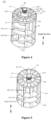
Figure 1 is a schematic diagram of an explosive structure of a control valve provided according to an embodiment of the present application; -
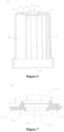
Figure 2 is a cross-sectional schematic diagram of the control valve shown inFigure 1 at a position; -
Figure 3 is a partial structural schematic diagram of a valve body provided according to an embodiment of the present application; -
Figure 4 is a structural schematic diagram of a valve core provided according to an embodiment of the present application; -
Figure 5 is a partial structural schematic diagram of the valve core shown inFigure 4 ; -
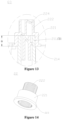
Figure 6 is a schematic diagram of a partial cross-sectional structure of the valve body shown inFigure 3 ; -
Figure 7 is a schematic diagram of an enlarged structure of the valve body shown inFigure 6 at position Q1; -
Figure 8 is a front view of a partial structure of the control valve shown inFigure 1 ; -
Figure 9 is a cross-sectional view of the control valve shown inFigure 8 along direction A-A; -
Figure 10 is a structural schematic diagram of the control valve shown inFigure 9 at position Q2; -
Figure 11 is a front structural schematic diagram of the valve core shown inFigure 4 ; -
Figure 12 is a cross-sectional view of the valve core shown inFigure 11 along direction B-B; -
Figure 13 is a schematic diagram of an enlarged structure of the valve core shown inFigure 12 at position Q3; -
Figure 14 is a structural schematic diagram of a second valve-core shaft provided according to an embodiment of the present application; -
Figure 15 is a schematic diagram of a cross-sectional structure of the second valve-core shaft shown inFigure 14 ; and -
Figure 16 is a flowchart of a method for manufacturing a control valve provided according to an embodiment of the present application. - Features and exemplary embodiments of various aspects of the present application are described in detail below. In order to make the purposes, technical solutions and advantages of the present application clearer, the present application is further described in detail below in conjunction with the drawings and specific embodiments. In this specification, relational terms such as "first" and "second" are only used to distinguish one element from another element with a same name, and do not necessarily require or imply any actual relationship or order between the elements.
- As shown in
Figures 1 to 3 , acontrol valve 1 is provided according to an embodiment of the present application. Thecontrol valve 1 includes avalve body 10, avalve core 20, and afirst sealing member 41. Thevalve body 10 includes aside wall part 11, and thecontrol valve 1 has avalve cavity 101. Theside wall part 11 forms a peripheral wall of thevalve cavity 101 or at least part of the peripheral wall. Thefirst sealing member 41 is arranged between thevalve core 20 and theside wall part 11 along a radial direction of thevalve core 20, and thevalve core 20 can be driven to rotate. Thecontrol valve 1 may further include adriving device 50 and asealing ring 43. Thedriving device 50 includes a driving member, the driving member may be a motor or a combination of a motor and a reduction gear set, and thevalve core 20 can be driven to rotate by the driving member in thedriving device 50. InFigure 1 , thevalve body 10 further includes abottom cover 12 and atop wall part 13. Thebottom cover 12 and thevalve cavity 101 are located between thetop wall part 13 and theside wall part 11, and thetop wall part 13 and theside wall part 11 are integrally formed. Thesealing ring 43 is arranged between thetop wall part 13 and thevalve core 20, and at least part of theside wall part 11 is arranged between thebottom cover 12 and thetop wall part 13. Thebottom cover 12 and theside wall part 11 may be fixedly connected and arranged in a sealed manner through a welding process to prevent fluid leakage. As at least part of thevalve core 20 penetrates through thetop wall part 13 to be located outside thevalve body 10 for transmission connection with thedriving device 50, by providing thesealing ring 43 located between thetop wall part 13 and thevalve core 20, fluid leakage from thetop wall 13 can be prevented, which improves the sealing performance of thecontrol valve 1. Thecontrol valve 1 may include at least fivechannels 30, one end of each of the at least fivechannels 30 penetrates theside wall part 11 and communicates with thevalve cavity 101, and the other end of each of the at least fivechannels 30 forms avalve port 102 of thecontrol valve 1, and fluid can enter or leave thecontrol valve 1 from thevalve port 102. - In order to facilitate the assembly of the
control valve 1 and other components in a fluid control system and improve the integration degree of thecontrol valve 1 and other components, in some embodiments, as shown inFigures 1 to 3 , thevalve body 10 further includes anmounting part 14, themounting part 14 is fixedly connected to theside wall part 11 and located on a side, facing away from thevalve cavity 101, of theside wall part 11. For example, themounting part 14 and theside wall part 11 may be integrally formed, themounting part 14 has a mounting surface 141, and thevalve port 102 of thecontrol valve 1 penetrates through the mounting surface 141, so that all thevalve ports 102 of thecontrol valve 1 are formed on the mounting surface 141 and the orientations of thevalve ports 102 are same, which can relatively simplify assembly steps of thecontrol valve 1 and other components, reduce leakage points of connecting portions, and improve the reliability of sealing. In some embodiments, thefirst sealing member 41 includes throughholes 411 that penetrate through thefirst sealing member 41, the throughholes 411 correspond to and communicate with at least part of thechannels 30 of thecontrol valve 1. Thefirst sealing member 41 is deformed by the pressure from thevalve core 20 and theside wall part 11, thereby realizing the sealing of thecontrol valve 1 by thefirst sealing member 41. It can be understood that the channels of thecontrol valve 1 may also be arranged along a circumferential direction of theside wall part 11, and thevalve ports 102 may also be arranged along the circumferential direction of theside wall part 11, which is not limited in the present application. - Further referring to
Figures 1 and2 , a cross section of the first sealingmember 41 is of an arc-shaped structure. When thevalve core 20 presses thefirst sealing member 41, it is easy to cause eccentricity of thevalve core 20, which easily affect the rotation of thevalve core 20. Therefore, in some embodiments, thecontrol valve 1 may further include asecond sealing member 42, thesecond sealing member 42 and thefirst sealing member 41 are respectively arranged on both sides of thevalve core 20 in the radial direction of thevalve core 20, so that thesecond sealing member 42 and thefirst sealing member 41 apply forces to thevalve core 20, thereby maintaining the coaxiality of thevalve core 20 and theside wall part 11, and improving the rotation stability of thevalve core 20. - As shown in
Figures 1 ,4, and 5 , thevalve core 20 has multipleouter communication cavities 25. Eachouter communication cavity 25 is a groove structure formed by recessing a side surface of thevalve core 20 toward an interior of thevalve core 20. During the rotation of thevalve core 20, corresponding twovalve ports 102 can be opened and/or closed through at least part of theouter communication cavities 25. Further, thevalve core 20 may further include aninner communication cavity 26, multipleouter communication cavities 25 are distributed on an outer peripheral side of theinner communication cavity 26. Theinner communication cavity 26 communicates with part of theouter communication cavities 25, so that during the rotation of thevalve core 20, the corresponding twovalve ports 102 can be opened and/or closed through theouter communication cavities 25 and theinner communication cavity 26, so as to realize the control of the fluid by thecontrol valve 1. - Further, the
valve core 20 includes atop plate 201, abottom plate 202, afirst partition 23, asecond partition 24, afirst block 203, and a valve-core shaft assembly SA. Thefirst partition 23 has a communication hole, and theinner communication cavity 26 communicates with part of theouter communication cavities 25 through the communication hole. Each of theouter communication cavities 25 is separated into an independent space by thesecond partition 24, and cross-sectional areas of cavity mouths of theouter communication cavities 25 may be different, for example, theouter communication cavities 25 may include afirst cavity 251 and asecond cavity 252. A cross-sectional area of a cavity mouth of thefirst cavity 251 is greater than or equal to twice a cross-sectional area of a cavity mouth of thesecond cavity 252. In this way, thefirst cavity 251 can open and/or close the twovalve ports 102 corresponding to thefirst cavity 251, and theinner communication cavity 26 communicates with the part of thesecond cavities 252 through the communication hole, so that theinner communication cavity 26 and the part of thesecond cavities 252 can open and/or close the twovalve ports 102 corresponding to theinner communication cavity 26 and the part of thesecond cavities 252. - The
top plate 201 and thebottom plate 202 of thevalve core 20 are arranged along a height direction of thevalve core 20, and theouter communication cavities 25 are located between thetop plate 201 and thebottom plate 202, and thetop plate 201 and thebottom plate 202 are mounted outside an outer peripheral side of the valve-core shaft assembly SA. The valve-core shaft assembly SA includes atransmission connection part 222, and at least part of thetransmission connection part 222 protrudes from thetop plate 201 and is located on a side of thetop plate 201 facing away from thebottom plate 202. Referring toFigure 1 , thevalve core 20 is in transmission connection with the drivingdevice 50 through thetransmission connection part 222, so that the drivingdevice 50 can drive thevalve core 20 to rotate through thetransmission connection part 222. Thefirst block 203 protrudes from thetop plate 201 and is fixedly connected to thetop plate 201 as an integral structure, or thefirst block 203 and thetop plate 201 may be separately provided and fixedly connected. In this way, the drivingdevice 50 is arranged close to thetop plate 201, thefirst block 203 extends from thetop plate 201 toward a direction away from thebottom plate 202, and thefirst block 203 can limit a rotation position of thevalve core 20. In the embodiment of the present application, since thefirst block 203 is fixedly connected to thetop plate 201 close to thetransmission connection part 222, thefirst block 203 is relatively close to thetransmission connection part 222 and the drivingdevice 50 when thefirst block 203 limits the rotation position of thevalve core 20, a driving force arm applied to thefirst block 203 is relatively small, which can reduce the torsional deformation of thevalve core 20 and improve the operational stability of thecontrol valve 1. In another embodiment, thevalve core 20 may further include a reinforcingrib 27, and the valve-core shaft assembly SA includes a first valve-core shaft 21 and a second valve-core shaft 22 that are in transmission connection. The first valve-core shaft 21 is in transmission connection with the drivingdevice 50 through the second valve-core shaft 22, and the reinforcingrib 27 is connected between thefirst partition 23 and the first valve-core shaft 21. Herein, the transmission connection of two components refers to that a transmission force can be transmitted between the two components, and the two components may be directly connected, or may be in transmission connection through a transmission mechanism such as a gear. - As shown in
Figures 6 to 10 , thevalve body 10 further includes atop wall part 13 located at an end of theside wall part 11 in the height direction of theside wall part 11 and asecond block 15. Thetop wall part 13 and theside wall part 11 are integrally formed and form part of a wall of thevalve cavity 101. Thetop wall part 13 has a throughhole 131, the throughhole 131 communicates with thevalve cavity 101. Thesecond block 15 is located in thevalve cavity 101 and protrudes from thetop wall part 13. At least part of thetransmission connection part 222 of the valve-core shaft assembly SA goes through the throughhole 131 to be located outside thevalve body 10. As shown inFigure 9 , the wholetransmission connection part 222 is arranged outside thevalve body 10, and thesecond block 15 is fixedly connected to thetop wall part 13 to form an integral structure. For example, thesecond block 15 may be integrally formed with thetop wall part 13. With reference toFigure 2 , when thevalve core 20 rotates to a predetermined position, thefirst block 203 abuts against thesecond block 15 and restricts thevalve core 20 from continuing to rotate towards thesecond block 15, so that thefirst block 203 and thesecond block 15 can form a position reference between thevalve core 20 and thevalve body 10, thereby making the rotation position of thevalve core 20 more accurate, so as to improve the control accuracy of thecontrol valve 1. Moreover, theside wall part 11, thetop wall part 13, and thesecond block 15 can be integrally formed, so that the structural strength of thevalve body 10 is improved when thefirst block 203 abuts against thesecond block 15. Compared with the embodiment of providing theside wall part 11 and thetop wall part 13 separately and fixing theside wall part 11 and thetop wall part 13 by welding, the structure of the embodiments of the present application can improve the cracking of a weld seam between theside wall part 11 and thetop wall part 13. - As shown in
Figures 10 to 15 , in order to improve the structural strength of thevalve core 20, in some embodiments, the valve-core shaft assembly SA includes a first valve-core shaft 21 and a second valve-core shaft 22, and the strength of the second valve-core shaft 22 is greater than the strength of the first valve-core shaft 21. The first valve-core shaft 21 includes a first connection part 211, and the first connection part 211 is located at an end of the first valve-core shaft 21 and at least part of the first connection part 211 is arranged in thevalve cavity 101. The second valve-core shaft 22 includes atransmission connection part 222 and asecond connection part 221, thetransmission connection part 222 of the valve-core shaft assembly SA is provided in the second valve-core shaft 22, and thetransmission connection part 222 is located at an end of the second valve-core shaft 22. The second valve-core shaft 22 further includes asecond connection part 221, thesecond connection part 221 and thetransmission connection part 222 are arranged along a height direction of the second valve-core shaft 22, at least part of thesecond connection part 221 is arranged in thevalve cavity 101, and at least part of thetransmission connection part 222 is arranged outside thevalve cavity 101 and protrudes from thetop wall part 13. An inner surface of one of thesecond connection part 221 and the first connection part 211 has teeth, an outer surface of the other of thesecond connection part 221 and the first connection part 211 has teeth, the teeth of thesecond connection part 221 meshes with the teeth of the first connection part 211. Through the above arrangement, on the basis of improving the structural strength of thevalve core 20, the first valve-core shaft 21 and the second valve-core shaft 22 can rotate synchronously. - In an embodiment, as shown in
Figures 12 to 15 , in order to improve anti-distortion strength of thevalve core 20 during rotation, thevalve core 20 may include a firstspiral reinforcing rib 213, a secondspiral reinforcing rib 214, and a thirdspiral reinforcing rib 224. The firstspiral reinforcing rib 213 is located between an outer surface of the first valve-core shaft 21 and an inner surface of thefirst partition 23, the secondspiral reinforcing rib 214 is located in a cavity enclosed by an inner surface of the first valve-core shaft 21, and the thirdspiral reinforcing rib 224 may be located in a cavity enclosed by an inner surface of the second valve-core shaft 22. In specific implementation, the firstspiral reinforcing rib 213, the secondspiral reinforcing rib 214, and the thirdspiral reinforcing rib 224 are spiral extension structures, the firstspiral reinforcing rib 213, the secondspiral reinforcing rib 214, the first valve-core shaft 21, thefirst partition 23, and thesecond partition 24 may be integrally formed by injection molding, and the thirdspiral reinforcing rib 224 may be integrally formed with the second valve-core shaft 22. - During specific implementation, the inner surface of the
second connection part 221 of the second valve-core shaft 22 is of a toothed structure, and the outer surface of the first connection part 211 of the first valve-core shaft 21 is of a toothed structure. The transmission connection between the first valve-core shaft 251 and the second valve-core shaft 22 is realized through the meshing of the toothed structures, so that the first valve-core shaft 251 and the second valve-core shaft 252 can rotate synchronously. In an embodiment, a constituent material of the first valve-core shaft 21 may be a combination of polyamide 66 (PA66) and glass fiber (GF), or a combination of polyphthalamide (PPA) and glass fiber (GF), or polyphenylene sulfide (PPS), a constituent material of the second valve-core shaft 22 may be one or a combination of metal and polyphenylene sulfide (PPS). In other embodiments, thecontrol valve 1 may not be provided with the second valve-core shaft 22, and the first valve-core shaft 21 may be in transmission connection with the driving device, so that the driving device drives the valve core to rotate. - In order to improve the stability of the transmission connection between the first valve-core shaft 21 and the second valve-
core shaft 22, in some embodiments, an output torque of thecontrol valve 1 is 3.5N.m to 4.5N.m, and an input torque of the valve-core shaft assembly SA is 3.5N.m to 4.5N.m. A length of a meshing part of the teeth of thesecond connection part 221 and the teeth of the first connection part 211 is 10mm to 15mm. - In some embodiments, a linear expansion coefficient of the second valve-
core shaft 22 is less than or equal to a linear expansion coefficient of the first valve-core shaft 21, so that the size change of the second valve-core shaft 22 is relatively small when the secondvalve core shaft 22 is at ambient temperature, which can make thecontrol valve 1 suitable for environments with various temperatures and improve the applicability of thecontrol valve 1. Further referring toFigures 10 to 15 , the second valve-core shaft 22 includes astep part 223, thestep part 223 is fixedly connected with thesecond connection part 221 to form an integrated structure, as shown inFigure 10 , or thestep part 223 and thesecond connection part 221 may be separately arranged but fixedly connected. Along the height direction of the second valve-core shaft 22, an orthographic projection of thesecond connection part 221 is located inside an orthographic projection of theannular step part 223. Thestep part 223 has astep surface 2231, thestep surface 2231 is disposed opposite to thetop wall part 13 and there is a gap between thestep surface 2231 and thetop wall part 13, and thestep surface 2231 is located in thevalve cavity 101. In a case that thecontrol valve 1 further includes the sealingring 43, the sealingring 43 is coaxial with a wall of the throughhole 131 of thetop wall part 13. The sealingring 43 is mounted on an outer peripheral side of the second valve-core shaft 22 and is arranged in the gap between thestep surface 2231 of the second valve-core shaft 22 and the inner surface of thetop wall part 13. By setting the linear expansion coefficient of the second valve-core shaft 22 to be less than or equal to the linear expansion coefficient of the first valve-core shaft 21, the size change of the second valve-core shaft 22 is relatively small when the second valve-core shaft 22 is at the ambient temperature, thereby reducing the deformation of the sealingring 43 and improving the sealing performance of thecontrol valve 1. - As shown in
Figures 7 and10 , in some embodiments, thevalve body 10 further includes aguide part 16, and theguide part 16 extends from thetop wall part 13 to thevalve cavity 101. Theguide part 16 has aguide channel 161 that penetrates through theguide part 16, and theguide channel 161 is coaxial with the wall of the throughhole 131 of thetop wall part 13 and communicates with the throughhole 131 of thetop wall part 13. Along a direction close to thetop wall part 13, and a bore diameter of an inner wall surface of theguide channel 161 decreases gradually, and the sealingring 43 is arranged inside theguide channel 161. The bore diameter of the inner wall surface of theguide channel 161 decreases gradually, so that when the sealingring 43 is assembled into thevalve body 10, the inner wall surface of theguide channel 161 plays a guiding role in the assembly of the sealingring 43, which facilitates the installation of the sealingring 43 and improves the accuracy of the installation position of the sealingring 43. - As shown in
Figures 1 ,2 ,4 ,8, and 9 , in some embodiments, in a case that thecontrol valve 1 further includes the drivingdevice 50, the drivingdevice 50 is located on a side, facing away from thevalve cavity 101, of thetop wall part 13. The drivingdevice 50 includes a driving member, and the driving member is in transmission connection with thetransmission connection part 222. Thefirst block 203 and thesecond block 15 are both close to the drivingdevice 50, so that when thevalve core 20 rotates until thefirst block 203 abuts against thesecond block 15, the driving force arm applied to thevalve core 50 is relatively small, which reduces the distortion deformation of thevalve core 20. Thevalve body 10 further includes abottom cover 12, thebottom cover 12 is located on a side, facing away from thetop wall part 13, of theside wall part 11, thebottom cover 12 and theside wall part 11 are fixedly arranged and thebottom cover 12 is sealingly connected to theside wall part 11. Thebottom cover 12 includes abottom wall part 121 and alimit part 122, and thelimit part 12 protrudes from thebottom wall part 121 and is arranged in thevalve cavity 101. The valve-core shaft assembly SA further includes asupport part 212, thesupport part 212 is located at an end, facing away from thetop plate 201, of the first valve-core shaft 21, and thesupport part 212 is located on a side of thebottom plate 202 of thevalve core 20. Thesupport part 212 is limitedly connected to thelimit part 122. Specifically, inFigure 9 , thelimit part 122 is of a groove structure, and thesupport part 212 is inserted into the groove structure. Through the above arrangement, the installation position of thevalve core 20 is accurate, and the rotation stability of thevalve core 20 is improved. - In summary, according to the
control valve 1 provided by the embodiments of the present application, by providing thefirst block 203 in thevalve core 20 and thesecond block 15 in thevalve body 10, thefirst block 203 abuts against thesecond block 15 and restricts thevalve core 20 from continuing to move towards thesecond block 15 when thevalve core 20 rotates to the predetermined position, so that the position reference is formed between thevalve core 20 and thevalve body 10, thereby making the rotation position of thevalve core 20 more accurate, so as to improve the control accuracy of thecontrol valve 1. Thevalve core 20 includes thetransmission connection part 222, and thetransmission connection part 222 can be in transmission connection with the drivingdevice 50 to drive thevalve core 20 to rotate. Thefirst block 203 is fixedly connected to thetop plate 201 close to thetransmission connection part 222, and thesecond block 15 is fixedly connected to thetop wall part 13 close to thetransmission connection part 222, so that when thefirst block 203 abuts against thesecond block 15, thefirst block 203 is relatively close to thetransmission connection part 222 and the drivingdevice 50, and the driving force arm applied on the isfirst block 203 is relatively small, which can reduce the torsional deformation ofvalve core 20 and improve the operational stability of thecontrol valve 1. - As shown in
Figure 16 , a method for manufacturing a control valve is further provided according to the embodiments of the present application. Referring toFigures 1 to 15 , the method for manufacturing a control valve includes the following steps S110 to S 160. - In step S110, a
valve core 20, avalve body 10, a sealingring 43, and abottom cover 12 are provided. - The
valve core 20 includes a valve-core shaft assembly SA, and the valve-core shaft assembly SA includes a first valve-core shaft 21 and a second valve-core shaft 22. The first valve-core shaft 21 includes a first connection part 211, and the second valve-core shaft 22 includes asecond connection part 221, astep part 223 and atransmission connection part 222. Thetransmission connection part 222 and thesecond connection part 221 are arranged along a height direction of the second valve-core shaft 22, and thestep part 223 is located on an outer peripheral side of thesecond connection part 221, and thestep part 223 and thesecond connection part 221 are fixedly connected to form an integrated structure, as shown inFigure 10 , or, thestep part 223 and thesecond connection part 221 may be arranged separately but fixedly connected. Thestep part 223 has astep surface 2231, and thestep surface 2231 may be perpendicular to the height direction of the secondvalve core axis 22. Thevalve body 10 includes aside wall part 11 and atop wall part 13, and thecontrol valve 1 has avalve cavity 101. Thetop wall part 13 and theside wall part 11 are integrally formed and define thevalve cavity 101. Thetop wall part 13 is located at one end of theside wall part 11, and the other end of theside wall part 11 has anopening 111 communicating with thevalve cavity 101. Thetop wall part 13 has a throughhole 131 that penetrates through thetop wall part 13, and the throughhole 131 communicates with thevalve cavity 101. Thevalve core 20 includes atop plate 201, abottom plate 202, afirst block 203, and the valve-core shaft assembly SA. Thetop plate 201 and thebottom plate 202 are arranged along a height direction of thevalve core 20. The valve-core shaft assembly SA includes thetransmission connection part 222, and at least part of thetransmission connection part 222 is located on a side, facing away from thebottom plate 202, of thetop plate 201. Thevalve body 10 further includes thetop wall part 13 and thesecond block 15, and thetop wall part 13 is disposed close to an end of theside wall part 11. The structures of thevalve body 10 and thevalve core 20 in the embodiments of the present application is the same as the structures of thevalve body 10 andvalve core 20 provided in any of the above embodiments, which are not repeated here. - In step S120, a valve core assembly is formed.
- In the embodiment, step S120 includes assembling the first valve-core shaft 21, the second valve-
core shaft 22, and the sealingring 43 to allow the first connection part 211 to be in transmission connection with thesecond connection part 221. The sealingring 43 is mounted on an outer peripheral side of the second valve-core shaft 22 and contacts thestep surface 2231 or there is a gap between the sealingring 43 and thestep surface 2231. In an embodiment, an inner diameter of the sealingring 43 is smaller than an outer diameter of the second valve-core shaft 22, so that the sealingring 43 is relatively stably limited on the second valve-core shaft 22. - In step S130, the valve core assembly is mounted into the
valve cavity 101 from theopening 111, and at least part of thetransmission connection part 222 is caused to go through the throughhole 131 to be located outside thevalve body 10. - Specifically, the
valve core 20 is mounted into thevalve cavity 101 from theopening 111, and at least part of thetransmission connection part 222 is caused to go through the throughhole 131 to be located outside thevalve body 10, so that when thevalve core 20 rotates to a predetermined position, thefirst block 203 abuts against thesecond block 15 and restricts thevalve core 20 from continuing to rotate towards thesecond block 15. - In step S140, the
bottom cover 12 is fixedly connected to an end, away from thetop wall part 13, of theside wall part 11, and thebottom cover 12 and the end, away from thetop wall part 13, of theside wall part 11 are arranged in a sealed manner. - In a case that the
control valve 1 includes the first sealingmember 41 and the second sealingmember 42, before step S130 that the valve core assembly is mounted into thevalve cavity 101 from theopening 111 and at least part of thetransmission connection part 222 goes through the throughhole 131 to be located outside thevalve body 10, the first sealingmember 41 and the second sealingmember 42 may be first mounted in thevalve cavity 101 to ensure that thecontrol valve 1 has a good sealing performance. The control valve manufactured by the above method for manufacturing a control valve has same beneficial effects as the control valve described above, and the deformation of the sealingring 43 can be improved, which are not repeated here. - In some embodiments, the
bottom cover 12 includes abottom wall part 121 and alimit part 122, thelimit part 122 protrudes from thebottom wall part 121, the first valve-core shaft 21 has asupport part 212, thesupport part 212 is located at one end of the first valve-core shaft 21, and the first connection part 211 is located at the other end of the first valve-core shaft 21. Step S140 that thebottom cover 12 is fixedly connected to an end, away from thetop wall part 13, of theside wall part 11, and thebottom cover 12 and the end, away from thetop wall part 13, of theside wall part 11 are arranged in a sealed manner includes: limitedly connecting thesupport part 212 to thelimit part 122; and fixedly connecting the bottom cover to the side wall part and arranging the bottom cover and the side wall part in a sealed manner through a welding process. In specific implementation, a whole circle may be welded around thebottom cover 12 and theside wall part 11 through a laser welding process, so that thebottom cover 12 and theside wall part 11 are fixedly connected and arranged in a sealed manner. - In order to make the first valve-core shaft 21 in stable transmission connection with the second valve-
core shaft 22 to better transmit a driving torque and prevent the fracture of the first valve-core shaft 21 and/or the second valve-core shaft 22, in some embodiments, an inner surface of one of thesecond connection part 221 and the first connection part 211 has teeth, and an outer surface of the other of thesecond connection part 221 and the first connection part 211 has teeth. In this way, step S120 that the valve core assembly is formed includes: forming the second valve-core shaft assembly including mounting the sealingring 43 on the outer peripheral side of the second valve-core shaft 22 and making the sealingring 43 contact or spaced apart from thestep surface 2231, where an inner diameter of the sealingring 43 is smaller than an outer diameter of thestep surface 2231; meshing the teeth of thesecond connection part 221 and the teeth of the first connection part 211 and making a length of a meshing part10mm to15mm. - It should be noted that the above embodiments are only used to illustrate the present application and not to limit the technical solutions described in the present application, For example, definitions for directions such as "front", "back", "left", "right", "up", "down". Although this specification has described the present application in detail with reference to the above embodiments, it should be understood that those skilled in the art can still modify, combine or replace the present application, all technical solutions and improvements thereof that do not deviate from the spirit and the scope of the present application shall fall within the scope of the claims of the present application.
Claims (13)
- A control valve comprising a valve body and a valve core, whereinthe valve body comprises a side wall part, the control valve has a valve cavity, and the side wall part forms at least part of a wall of the valve cavity, at least part of the valve core is located in the valve cavity and is configured to be driven to rotate, the valve core comprises a top plate, a bottom plate, a first block, and a valve-core shaft assembly, the top plate and the bottom plate are arranged along a height direction of the valve core, the valve-core shaft assembly comprises a transmission connection part, at least part of the transmission connection part is located on a side, facing away from the bottom plate, of the top plate, the valve core is configured to be driven to rotate through the transmission connection part, and the first block is connected to the top plate; andthe valve body further comprises a top wall part and a second block, the top wall part is arranged close to an end of the side wall part, the top wall part has a through hole, which communicates with the valve cavity, at least part of the transmission connection part goes through the through hole to be located outside the valve body, the second block is located in the valve cavity and protrudes from the top wall part, and when the valve core rotates to a predetermined position, the first block abuts against the second block and restricts the valve core from continuing to rotate towards the second block.
- The control valve according to claim 1, wherein the first block extends from the top plate towards a direction away from the bottom plate, the top wall part and the side wall part are integrally formed, the second block is fixedly connected to the top wall part to form an integral structure, and the first block is fixedly connected to the top plate to form an integral structure.
- The control valve according to claim 1, wherein the valve-core shaft assembly comprises a first valve-core shaft and a second valve-core shaft, a strength of the second valve-core shaft is greater than a strength of the first valve-core shaft, the first valve-core shaft comprises a first connection part, the first connection part is located at an end of the first valve-core shaft and at least part of the first connection part is located in the valve cavity, the second valve-core shaft comprises the transmission connection part, the second valve-core shaft further comprises a second connection part, the second connection part and the transmission connection part are provided along a height direction of the second valve-core shaft and at least part of the second connection part is located in the valve cavity, and at least part of the transmission connection part is located outside the valve cavity and protrudes from the top wall part.
- The control valve according to claim 3, wherein an inner surface of one of the second connection part and the first connection part has teeth, and an outer surface of the other one of the second connection part and the first connection part has teeth, the teeth of the second connection part meshes with the teeth of the first connection part.
- The control valve according to claim 4, wherein an input torque of the valve-core shaft assembly is 3.5N.m to 4.5N.m; and
a length of a meshing part of the teeth of the second connection part and the teeth of the first connection part is 10mm to 15mm. - The control valve according to claim 3, whereina constituent material of the first valve-core shaft comprises a combination of polyamide-66 and glass fiber, or a combination of polyphthalamide and glass fiber, or polyphenylene sulfide; anda constituent material of the second valve-core shaft comprises one or a combination of metal and polyphenylene sulfide.
- The control valve according to claim 3, whereina linear expansion coefficient of the second valve-core shaft is less than or equal to a linear expansion coefficient of the first valve-core shaft, the second valve-core shaft comprises a step part, the step part has a step surface, and the step surface is located in the valve cavity and is arranged opposite to the top wall part; andthe control valve further comprises a sealing ring, the sealing ring is coaxial with a wall of the through hole of the top wall part, the sealing ring is mounted on an outer peripheral side of the second valve-core shaft and is arranged between the step surface of the second valve-core shaft and the top wall part.
- The control valve according to claim 7, whereinthe valve body further comprises a guide part, the guide part extends from the top wall part to the valve cavity, the guide part has a guide channel that penetrates through the guide part, the guide channel is coaxial with the through hole of the top wall part and communicates with the through hole of the top wall part, and the sealing ring is arranged in the guide channel; andalong a direction close to the top wall part, a bore diameter of the guide channel decreases gradually.
- The control valve according to any one of claims 1 to 8, further comprising a driving device, whereinthe driving device is located on a side of the top wall part facing away from the valve cavity, the driving device comprises a driving member, and the driving member is in transmission connection with the transmission connection part;the valve body further comprises a bottom cover, the bottom cover is located on a side of the side wall part facing away from the top wall part, the bottom cover and the side wall part are fixedly arranged and sealingly connected, the bottom cover comprises a bottom wall part and a limit part, the limit part protrudes from the bottom wall part and is located in the valve cavity, the valve-core shaft assembly further comprises a support part, the support part is located on a side of the bottom plate of the valve core facing away from the top plate, the support part is limitedly connected to the limit part.
- A method for manufacturing a control valve, comprising:providing a valve core, a valve body, and a bottom cover, wherein the valve body comprises a side wall part, the control valve has a valve cavity, the side wall part forms at least part of the wall of the valve cavity, the valve core comprises a top plate, a bottom plate, a first block, and a valve-core shaft assembly, the top plate and the bottom plate are arranged along a height direction of the valve core, the valve-core shaft assembly comprises a transmission connection part, at least part of the transmission connection part is located on a side, facing away from the bottom plate, of the top plate, the valve body further comprises a top wall part and a second block, the top wall part is arranged close to one end of the side wall part, the top wall part has a through hole, which communicates with the valve cavity, and the other end of the side wall part has an opening communicating with the valve cavity;mounting the valve core into the valve cavity from the opening, and making at least part of the transmission connection part go through the through hole to be located outside the valve body, so as to allow the first block to abut against the second block and restrict the valve core from continuing to rotate towards the second block, when the valve core rotates to a predetermined position; andfixedly connecting the bottom cover to an end, away from the top wall part, of the side wall part, and arranging the bottom cover and the end, away from the top wall part, of the side wall part in a sealed manner.
- The method for manufacturing a control valve according to claim 10, whereinthe valve-core shaft assembly comprises a first valve-core shaft and a second valve-core shaft, the first valve-core shaft comprises a first connection part, the second valve-core shaft comprises a second connection part, a step part, and a transmission connection part, and the transmission connection part and the second connection part are arranged along a height direction of the second valve-core shaft, the step part is located on an outer peripheral side of the second connection part, and the step part has a step surface;after providing the valve core, the valve body, and the bottom cover, the method further comprises:
assembling the first valve-core shaft, the second valve-core shaft, and the sealing ring to allow the first connection part to be in transmission connection the second connection part drive, wherein the sealing ring is mounted on an outer peripheral side of the second valve-core shaft and contacts the step surface or there is a gap between the sealing ring and the step surface. - The method for manufacturing a control valve according to claim 11, whereinthe bottom cover comprises a bottom wall part and a limit part, the limit part protrudes from the bottom wall part, and the first valve-core shaft has a support part,fixedly connecting the bottom cover to the end of the side wall part away from the top wall part, and arranging the bottom cover and the end of the side wall part away from the top wall part in a sealed manner comprises:limitedly connecting the support part to the limit part; andfixedly connecting the bottom cover to the end of the side wall part and arranging the bottom cover and the end of the side wall part in a sealed manner through a welding process.
- The method for manufacturing a control valve according to claim 11 or 12, wherein an inner surface of one of the second connection part and the first connection part has teeth, and an outer surface of the other of the second connection part and the first connection part has teeth,
assembling the first valve-core shaft, the second valve-core shaft, and the sealing ring comprises:forming a second valve-core shaft assembly, comprising mounting the sealing ring on the outer peripheral side of the second valve-core shaft and making the sealing ring contact or spaced apart from the step surface, wherein an inner diameter of the sealing ring is smaller than an outer diameter of the step surface; andmeshing the teeth of the second connection part and the teeth of the first connection part and making a length of a meshing part 10mm to 15mm.
Applications Claiming Priority (2)
| Application Number | Priority Date | Filing Date | Title |
|---|---|---|---|
| CN202110411384.6A CN115218003A (en) | 2021-04-16 | 2021-04-16 | Control valve and method for manufacturing the same |
| PCT/CN2022/087033 WO2022218405A1 (en) | 2021-04-16 | 2022-04-15 | Control valve and manufacturing method therefor |
Publications (1)
| Publication Number | Publication Date |
|---|---|
| EP4325100A1 true EP4325100A1 (en) | 2024-02-21 |
Family
ID=83605735
Family Applications (1)
| Application Number | Title | Priority Date | Filing Date |
|---|---|---|---|
| EP22787627.3A Pending EP4325100A1 (en) | 2021-04-16 | 2022-04-15 | Control valve and manufacturing method therefor |
Country Status (4)
| Country | Link |
|---|---|
| EP (1) | EP4325100A1 (en) |
| JP (1) | JP2024513613A (en) |
| CN (1) | CN115218003A (en) |
| WO (1) | WO2022218405A1 (en) |
Families Citing this family (1)
| Publication number | Priority date | Publication date | Assignee | Title |
|---|---|---|---|---|
| CN115654177B (en) * | 2022-12-26 | 2023-03-14 | 四川芯智热控技术有限公司 | Multi-way valve |
Family Cites Families (9)
| Publication number | Priority date | Publication date | Assignee | Title |
|---|---|---|---|---|
| JP2006009830A (en) * | 2004-06-22 | 2006-01-12 | Hitachi Valve Ltd | Ball valve made of resin |
| JP4706981B2 (en) * | 2008-06-13 | 2011-06-22 | Toto株式会社 | Cylinder valve |
| CN201246487Y (en) * | 2008-08-19 | 2009-05-27 | 浙江盾安禾田金属有限公司 | Ball valve switch structure |
| CN104896147A (en) * | 2015-04-23 | 2015-09-09 | 武汉理工大学 | Tee reversing valve |
| CN107202173B (en) * | 2017-06-09 | 2019-01-01 | 立信阀门集团有限公司 | Water regulating valve |
| CN109237054B (en) * | 2017-07-11 | 2020-06-23 | 浙江三花制冷集团有限公司 | Rotary switching valve |
| CN109424766B (en) * | 2017-08-28 | 2022-07-12 | 浙江三花制冷集团有限公司 | Rotary reversing valve |
| JP6684837B2 (en) * | 2018-01-29 | 2020-04-22 | 株式会社不二工機 | Motorized valve |
| CN108708992A (en) * | 2018-08-07 | 2018-10-26 | 台州力和环保科技有限公司 | A kind of spool |
-
2021
- 2021-04-16 CN CN202110411384.6A patent/CN115218003A/en active Pending
-
2022
- 2022-04-15 WO PCT/CN2022/087033 patent/WO2022218405A1/en active Application Filing
- 2022-04-15 EP EP22787627.3A patent/EP4325100A1/en active Pending
- 2022-04-15 JP JP2023563235A patent/JP2024513613A/en active Pending
Also Published As
| Publication number | Publication date |
|---|---|
| JP2024513613A (en) | 2024-03-26 |
| WO2022218405A1 (en) | 2022-10-20 |
| CN115218003A (en) | 2022-10-21 |
Similar Documents
| Publication | Publication Date | Title |
|---|---|---|
| EP4325100A1 (en) | Control valve and manufacturing method therefor | |
| US20220025977A1 (en) | Ball valve | |
| US7475704B2 (en) | Valve drive device | |
| KR20010020173A (en) | Fluid machine | |
| CN113785148B (en) | flow control valve | |
| EP4325101A1 (en) | Control valve | |
| CN112081978B (en) | Control valve | |
| WO2023143060A1 (en) | Electric valve and manufacturing method therefor | |
| GB2158148A (en) | Door closer | |
| CN114165621B (en) | Piston type reversing valve | |
| CN216843174U (en) | Electronic expansion valve | |
| US11378197B2 (en) | Valve | |
| EP4325104A1 (en) | Control valve and sealing component | |
| CN116557565A (en) | Electric valve | |
| KR102364496B1 (en) | A actuator for a vechicle | |
| EP4095420A1 (en) | Flow modulator for a fluid | |
| CN117823656A (en) | Valve module, electric valve and manufacturing method thereof | |
| JP2019528413A (en) | Sleeve assembly, control valve having the same, and air conditioning system | |
| CN115704495A (en) | Control valve | |
| JP2000345867A (en) | Motor-operated throttle valve device | |
| CN115992888A (en) | Flow regulating valve and manufacturing method | |
| CN115596855A (en) | Electric valve | |
| CN112576797A (en) | Electric valve | |
| CN115467836A (en) | Fluid management device | |
| CN116538302A (en) | Electronic expansion valve |
Legal Events
| Date | Code | Title | Description |
|---|---|---|---|
| STAA | Information on the status of an ep patent application or granted ep patent |
Free format text: STATUS: THE INTERNATIONAL PUBLICATION HAS BEEN MADE |
|
| PUAI | Public reference made under article 153(3) epc to a published international application that has entered the european phase |
Free format text: ORIGINAL CODE: 0009012 |
|
| STAA | Information on the status of an ep patent application or granted ep patent |
Free format text: STATUS: REQUEST FOR EXAMINATION WAS MADE |
|
| 17P | Request for examination filed |
Effective date: 20231019 |
|
| AK | Designated contracting states |
Kind code of ref document: A1 Designated state(s): AL AT BE BG CH CY CZ DE DK EE ES FI FR GB GR HR HU IE IS IT LI LT LU LV MC MK MT NL NO PL PT RO RS SE SI SK SM TR |