EP4325043A1 - Fuel pressure accumulating device - Google Patents
Fuel pressure accumulating device Download PDFInfo
- Publication number
- EP4325043A1 EP4325043A1 EP22828146.5A EP22828146A EP4325043A1 EP 4325043 A1 EP4325043 A1 EP 4325043A1 EP 22828146 A EP22828146 A EP 22828146A EP 4325043 A1 EP4325043 A1 EP 4325043A1
- Authority
- EP
- European Patent Office
- Prior art keywords
- fuel
- pressure accumulating
- fuel pressure
- pressure
- pressure accumulator
- Prior art date
- Legal status (The legal status is an assumption and is not a legal conclusion. Google has not performed a legal analysis and makes no representation as to the accuracy of the status listed.)
- Pending
Links
Images




Classifications
-
- F—MECHANICAL ENGINEERING; LIGHTING; HEATING; WEAPONS; BLASTING
- F02—COMBUSTION ENGINES; HOT-GAS OR COMBUSTION-PRODUCT ENGINE PLANTS
- F02M—SUPPLYING COMBUSTION ENGINES IN GENERAL WITH COMBUSTIBLE MIXTURES OR CONSTITUENTS THEREOF
- F02M55/00—Fuel-injection apparatus characterised by their fuel conduits or their venting means; Arrangements of conduits between fuel tank and pump F02M37/00
- F02M55/02—Conduits between injection pumps and injectors, e.g. conduits between pump and common-rail or conduits between common-rail and injectors
- F02M55/025—Common rails
-
- F—MECHANICAL ENGINEERING; LIGHTING; HEATING; WEAPONS; BLASTING
- F02—COMBUSTION ENGINES; HOT-GAS OR COMBUSTION-PRODUCT ENGINE PLANTS
- F02M—SUPPLYING COMBUSTION ENGINES IN GENERAL WITH COMBUSTIBLE MIXTURES OR CONSTITUENTS THEREOF
- F02M55/00—Fuel-injection apparatus characterised by their fuel conduits or their venting means; Arrangements of conduits between fuel tank and pump F02M37/00
- F02M55/02—Conduits between injection pumps and injectors, e.g. conduits between pump and common-rail or conduits between common-rail and injectors
-
- F—MECHANICAL ENGINEERING; LIGHTING; HEATING; WEAPONS; BLASTING
- F02—COMBUSTION ENGINES; HOT-GAS OR COMBUSTION-PRODUCT ENGINE PLANTS
- F02M—SUPPLYING COMBUSTION ENGINES IN GENERAL WITH COMBUSTIBLE MIXTURES OR CONSTITUENTS THEREOF
- F02M37/00—Apparatus or systems for feeding liquid fuel from storage containers to carburettors or fuel-injection apparatus; Arrangements for purifying liquid fuel specially adapted for, or arranged on, internal-combustion engines
- F02M37/0011—Constructional details; Manufacturing or assembly of elements of fuel systems; Materials therefor
- F02M37/0017—Constructional details; Manufacturing or assembly of elements of fuel systems; Materials therefor related to fuel pipes or their connections, e.g. joints or sealings
-
- F—MECHANICAL ENGINEERING; LIGHTING; HEATING; WEAPONS; BLASTING
- F02—COMBUSTION ENGINES; HOT-GAS OR COMBUSTION-PRODUCT ENGINE PLANTS
- F02M—SUPPLYING COMBUSTION ENGINES IN GENERAL WITH COMBUSTIBLE MIXTURES OR CONSTITUENTS THEREOF
- F02M55/00—Fuel-injection apparatus characterised by their fuel conduits or their venting means; Arrangements of conduits between fuel tank and pump F02M37/00
- F02M55/002—Arrangement of leakage or drain conduits in or from injectors
-
- F—MECHANICAL ENGINEERING; LIGHTING; HEATING; WEAPONS; BLASTING
- F02—COMBUSTION ENGINES; HOT-GAS OR COMBUSTION-PRODUCT ENGINE PLANTS
- F02M—SUPPLYING COMBUSTION ENGINES IN GENERAL WITH COMBUSTIBLE MIXTURES OR CONSTITUENTS THEREOF
- F02M55/00—Fuel-injection apparatus characterised by their fuel conduits or their venting means; Arrangements of conduits between fuel tank and pump F02M37/00
- F02M55/004—Joints; Sealings
-
- F—MECHANICAL ENGINEERING; LIGHTING; HEATING; WEAPONS; BLASTING
- F02—COMBUSTION ENGINES; HOT-GAS OR COMBUSTION-PRODUCT ENGINE PLANTS
- F02M—SUPPLYING COMBUSTION ENGINES IN GENERAL WITH COMBUSTIBLE MIXTURES OR CONSTITUENTS THEREOF
- F02M61/00—Fuel-injectors not provided for in groups F02M39/00 - F02M57/00 or F02M67/00
- F02M61/16—Details not provided for in, or of interest apart from, the apparatus of groups F02M61/02 - F02M61/14
-
- F—MECHANICAL ENGINEERING; LIGHTING; HEATING; WEAPONS; BLASTING
- F02—COMBUSTION ENGINES; HOT-GAS OR COMBUSTION-PRODUCT ENGINE PLANTS
- F02M—SUPPLYING COMBUSTION ENGINES IN GENERAL WITH COMBUSTIBLE MIXTURES OR CONSTITUENTS THEREOF
- F02M63/00—Other fuel-injection apparatus having pertinent characteristics not provided for in groups F02M39/00 - F02M57/00 or F02M67/00; Details, component parts, or accessories of fuel-injection apparatus, not provided for in, or of interest apart from, the apparatus of groups F02M39/00 - F02M61/00 or F02M67/00; Combination of fuel pump with other devices, e.g. lubricating oil pump
- F02M63/02—Fuel-injection apparatus having several injectors fed by a common pumping element, or having several pumping elements feeding a common injector; Fuel-injection apparatus having provisions for cutting-out pumps, pumping elements, or injectors; Fuel-injection apparatus having provisions for variably interconnecting pumping elements and injectors alternatively
- F02M63/0205—Fuel-injection apparatus having several injectors fed by a common pumping element, or having several pumping elements feeding a common injector; Fuel-injection apparatus having provisions for cutting-out pumps, pumping elements, or injectors; Fuel-injection apparatus having provisions for variably interconnecting pumping elements and injectors alternatively for cutting-out pumps or injectors in case of abnormal operation of the engine or the injection apparatus, e.g. over-speed, break-down of fuel pumps or injectors ; for cutting-out pumps for stopping the engine
- F02M63/0215—Fuel-injection apparatus having several injectors fed by a common pumping element, or having several pumping elements feeding a common injector; Fuel-injection apparatus having provisions for cutting-out pumps, pumping elements, or injectors; Fuel-injection apparatus having provisions for variably interconnecting pumping elements and injectors alternatively for cutting-out pumps or injectors in case of abnormal operation of the engine or the injection apparatus, e.g. over-speed, break-down of fuel pumps or injectors ; for cutting-out pumps for stopping the engine by draining or closing fuel conduits
-
- F—MECHANICAL ENGINEERING; LIGHTING; HEATING; WEAPONS; BLASTING
- F02—COMBUSTION ENGINES; HOT-GAS OR COMBUSTION-PRODUCT ENGINE PLANTS
- F02M—SUPPLYING COMBUSTION ENGINES IN GENERAL WITH COMBUSTIBLE MIXTURES OR CONSTITUENTS THEREOF
- F02M63/00—Other fuel-injection apparatus having pertinent characteristics not provided for in groups F02M39/00 - F02M57/00 or F02M67/00; Details, component parts, or accessories of fuel-injection apparatus, not provided for in, or of interest apart from, the apparatus of groups F02M39/00 - F02M61/00 or F02M67/00; Combination of fuel pump with other devices, e.g. lubricating oil pump
- F02M63/02—Fuel-injection apparatus having several injectors fed by a common pumping element, or having several pumping elements feeding a common injector; Fuel-injection apparatus having provisions for cutting-out pumps, pumping elements, or injectors; Fuel-injection apparatus having provisions for variably interconnecting pumping elements and injectors alternatively
- F02M63/0225—Fuel-injection apparatus having a common rail feeding several injectors ; Means for varying pressure in common rails; Pumps feeding common rails
- F02M63/0275—Arrangement of common rails
- F02M63/0285—Arrangement of common rails having more than one common rail
-
- F—MECHANICAL ENGINEERING; LIGHTING; HEATING; WEAPONS; BLASTING
- F02—COMBUSTION ENGINES; HOT-GAS OR COMBUSTION-PRODUCT ENGINE PLANTS
- F02M—SUPPLYING COMBUSTION ENGINES IN GENERAL WITH COMBUSTIBLE MIXTURES OR CONSTITUENTS THEREOF
- F02M65/00—Testing fuel-injection apparatus, e.g. testing injection timing ; Cleaning of fuel-injection apparatus
- F02M65/006—Measuring or detecting fuel leakage of fuel injection apparatus
-
- Y—GENERAL TAGGING OF NEW TECHNOLOGICAL DEVELOPMENTS; GENERAL TAGGING OF CROSS-SECTIONAL TECHNOLOGIES SPANNING OVER SEVERAL SECTIONS OF THE IPC; TECHNICAL SUBJECTS COVERED BY FORMER USPC CROSS-REFERENCE ART COLLECTIONS [XRACs] AND DIGESTS
- Y02—TECHNOLOGIES OR APPLICATIONS FOR MITIGATION OR ADAPTATION AGAINST CLIMATE CHANGE
- Y02E—REDUCTION OF GREENHOUSE GAS [GHG] EMISSIONS, RELATED TO ENERGY GENERATION, TRANSMISSION OR DISTRIBUTION
- Y02E60/00—Enabling technologies; Technologies with a potential or indirect contribution to GHG emissions mitigation
- Y02E60/30—Hydrogen technology
- Y02E60/50—Fuel cells
-
- Y—GENERAL TAGGING OF NEW TECHNOLOGICAL DEVELOPMENTS; GENERAL TAGGING OF CROSS-SECTIONAL TECHNOLOGIES SPANNING OVER SEVERAL SECTIONS OF THE IPC; TECHNICAL SUBJECTS COVERED BY FORMER USPC CROSS-REFERENCE ART COLLECTIONS [XRACs] AND DIGESTS
- Y02—TECHNOLOGIES OR APPLICATIONS FOR MITIGATION OR ADAPTATION AGAINST CLIMATE CHANGE
- Y02T—CLIMATE CHANGE MITIGATION TECHNOLOGIES RELATED TO TRANSPORTATION
- Y02T10/00—Road transport of goods or passengers
- Y02T10/10—Internal combustion engine [ICE] based vehicles
- Y02T10/12—Improving ICE efficiencies
Definitions
- the present disclosure relates to a fuel pressure accumulating device applied to an internal combustion engine.
- a common rail type fuel injection device applied to a diesel engine includes a fuel pump, a common rail (fuel pressure accumulating device), and a fuel injector.
- the fuel pump sucks a fuel from the fuel tank, pressurizes the fuel, and supplies the fuel to the common rail as a high-pressure fuel.
- the common rail maintains the high-pressure fuel supplied from the fuel pump at a predetermined pressure.
- the fuel injector opens and closes an injection valve to inject the high-pressure fuel from the common rail into a combustion chamber of the diesel engine.
- the common rail is an accumulator that maintains a high-pressure fuel at a predetermined pressure, and is connected to a fuel pump and a plurality of fuel injectors. As such a common rail, for example, there are common rails disclosed in PTL 1.
- the number of fuel injectors corresponding to the number of cylinders of a diesel engine is connected to the common rail.
- some common rails have a total length of more than 2 m.
- a common rail has a split structure.
- a common rail a plurality of connectors are attached to rail portions, and a fuel injector is connected to each connector via a pipe.
- a fuel may leak from an attachment portion of the connector to the rail portion.
- the common rail has a split structure, the number of fuel leakage locations increases. Therefore, it is conceivable to cover the rail portion itself with a cover and to catch a fuel leaking from the attachment portion of the connector with the cover.
- this configuration has a problem that a size of the common rail is increased.
- the present disclosure has been made to solve the above-described problems, and an object of the present disclosure is to provide a fuel pressure accumulating device capable of recovering a leaked fuel and suppressing an increase in the size of the device.
- a fuel pressure accumulating device including a fuel pressure accumulator in which a pressure accumulating space is provided; a fuel inflow portion that is attached to the fuel pressure accumulator and allows a fuel to flow into the pressure accumulating space; a fuel outflow portion that is attached to the fuel pressure accumulator and allows the fuel to flow out from the pressure accumulating space; and a fuel storage portion that is provided in the fuel pressure accumulator, and stores the fuel that has leaked at an attachment position of the fuel inflow portion in the fuel pressure accumulator and an attachment position of the fuel outflow portion in the fuel pressure accumulators.
- the fuel pressure accumulating device of the present disclosure it is possible to recover a leaked fuel, and it is possible to suppress an increase in the size of the device.
- the present disclosure is not limited by the embodiment, and in a case where there are a plurality of embodiments, the present disclosure also includes a configuration in which the respective embodiments are combined with each other.
- constituents in the embodiment include constituents that can be easily assumed by those skilled in the art, constituents that are substantially the same, and constituents having a so-called equivalent range.
- Fig. 1 is a schematic configuration diagram illustrating a fuel injection device of the present embodiment.
- a fuel injection device 10 is attached to a diesel engine (internal combustion engine).
- the fuel injection device 10 includes a fuel pump 11, a common rail (fuel pressure accumulating device) 12, and a plurality of fuel injectors 13.
- a fuel tank 14 is connected to the fuel pump 11 via a fuel line L11.
- the fuel pump 11 sucks a fuel stored in the fuel tank 14 from the fuel line L11 and pressurizes the fuel to generate a high-pressure fuel.
- the common rail 12 is connected to the fuel pump 11 via a fuel high-pressure line L12.
- the common rail 12 includes a plurality of rail portions 21, 22, and 23. The number of rail portions 21, 22, and 23 is appropriately set according to a form of the diesel engine.
- the plurality of rail portions 21, 22, and 23 are connected in series via connection lines L21 and L22.
- the plurality of rail portions 21, 22, and 23 may be connected in parallel via connection lines.
- the common rail 12 adjusts the high-pressure fuel supplied from the fuel pump 11 to a predetermined pressure.
- the fuel injectors 13 are connected to the common rail 12 via a plurality of fuel supply lines L13.
- the fuel injector 13 opens and closes the injection valve to inject the high-pressure fuel in the common rail 12 into each cylinder (combustion chamber) of the diesel engine.
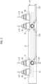
- Fig. 2 is a front view illustrating the fuel pressure accumulating device of the present embodiment.
- the common rail 12 as a fuel pressure accumulating device includes a plurality of rail portions 21, 22, and 23.
- the common rail 12 may include a single rail portion 21.
- the fuel pressure accumulating device is the common rail 12, and is also the single rail portion 21. Since the rail portions 21, 22, and 23 have substantially the same configuration, the rail portion 21 will be described in detail below.
- the rail portion 21 includes a fuel pressure accumulator 31, a fuel inflow portion 32, fuel outflow portions 33, 34, and 35, and fuel storage portions 36 and 37.
- the fuel pressure accumulator 31 is a pressure vessel having a long shape.
- a pressure accumulating space 41 is provided inside the fuel pressure accumulator 31.
- one fuel inflow portion 32 and three fuel outflow portions 33, 34, and 35 are attached at intervals in the longitudinal direction.
- the number of the fuel outflow portions 33, 34, and 35 is not limited to three.
- the fuel inflow portion 32 can cause a fuel to flow from the outside into the pressure accumulating space 41.
- the fuel outflow portions 33, 34, and 35 can cause the fuel to flow out from the pressure accumulating space to the outside.
- the fuel inflow portion 32 is connected to the fuel high-pressure line L12 from the fuel pump 11 (refer to Fig. 1 ).
- the fuel injectors 13 (refer to Fig. 1 ) are connected to the fuel outflow portions 33 and 34 via the fuel supply lines L13.
- the fuel outflow portion 35 is connected to the fuel inflow portion 32 of the fuel pressure accumulator 31 in the rail portion 22 that is disposed adjacently via the connection line L21.
- the fuel storage portions 36 and 37 are provided in the fuel pressure accumulator 31.
- the fuel storage portions 36 and 37 store a fuel that has flowed out at the attachment position of the fuel inflow portion 32 in the fuel pressure accumulator 31 and at the attachment positions of the fuel outflow portions 33, 34, and 35 in the fuel pressure accumulator 31.
- the fuel storage portion 36 stores the fuel that has flowed out from the fuel inflow portion 32 and the fuel outflow portion 33 in the fuel pressure accumulator 31.
- the fuel storage portion 37 stores the fuel that has flowed out from the fuel outflow portions 34 and 35 in the fuel pressure accumulator 31.
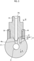
- Fig. 3 is a vertical cross section illustrating a rail portion
- Fig. 4 is a sectional view taken along line IV-IV in Fig. 3
- Fig. 5 is a sectional view taken along line V-V in Fig. 3
- Fig. 6 is a sectional view taken along line VI-VI in Fig. 5 .
- the fuel pressure accumulator 31 is provided with the pressure accumulating space 41 penetrating in the longitudinal direction.
- the pressure accumulating space 41 is provided in the longitudinal direction, and respective end portions thereof in the longitudinal direction are closed by plugs 42 and 43.
- the fuel inflow portion 32 and the fuel outflow portions 33, 34, and 35 are, for example, connectors, and fuel flow holes 32a, 33a, 34a, and 35a are formed in the centers thereof.
- the plugs 42 and 43 close the pressure accumulating space 41 by being fixed to the end portions thereof in the fuel pressure accumulator 31.
- a seal member such as an O-ring is provided between the pressure accumulating space 41 and the plugs 42 and 43, or does not need to be provided.
- Tubular attachment portions 44, 45, 46, and 47 are fixed to the fuel pressure accumulators 31 at intervals in the longitudinal direction.
- the tubular attachment portions 44, 45, 46, and 47 are disposed in a direction orthogonal to the longitudinal direction of the pressure accumulating space 41.
- Axial end portions of the fuel inflow portion 32 and the fuel outflow portions 33, 34, and 35 are fitted and fixed to the tubular attachment portions 44, 45, 46, and 47 via O-rings (seal members) 48, 49, 50, and 51.
- the O-rings 48, 49, 50, and 51 are provided between the fuel inflow portion 32 and the fuel outflow portions 33, 34, and 35 and the tubular attachment portions 44, 45, 46, and 47, but does not need to be provided.
- communication holes 44a, 45a, 46a, and 47a that allow the pressure accumulating space 41 and the outside to communicate with each other are formed inside the tubular attachment portions 44, 45, 46, and 47.
- the fuel flow holes 32a, 33a, 34a, and 35a communicate with the pressure accumulating space 41 through the communication holes 44a, 45a, 46a, and 47a.
- the outer peripheral portions of the fuel inflow portion 32 and the fuel outflow portions 33, 34, and 35 are screw-fastened to the inner peripheral portions of the tubular attachment portions 44, 45, 46, and 47.
- the O-rings 48, 49, 50, and 51 are interposed between the fuel inflow portion 32 and the fuel outflow portions 33, 34, and 35 and the tubular attachment portions 44, 45, 46, and 47.
- Space regions A1, A2, A3, and A4 defined by the fuel inflow portion 32, the fuel outflow portion 33, 34, 35, the tubular attachment portions 44, 45, 46, 47, the O-ring 48, 49, 50, 51, and the fuel pressure accumulator 31 are formed.
- the fuel leaking from the connecting portions between the fuel flow holes 32a, 33a, 34a, 35a and the communication holes 44a, 45a, 46a, 47a flows to the space regions A1, A2, A3, and A4 that are attachment positions of the fuel inflow portion 32 and the fuel outflow portions 33, 34, and 35.
- the fuel storage portions 36 and 37 communicate with the space regions A1, A2, A3, and A4, and store the leaked fuel in the space regions A1, A2, A3, and A4.
- the fuel storage portion 36 is provided to correspond to the fuel inflow portion 32 and the fuel outflow portion 33, and the fuel storage portion 37 is provided to correspond to the fuel outflow portions 34 and 35.
- the fuel storage portion 36 has a first flow path 61 and second flow paths 62 and 63.
- the fuel storage portion 37 has a first flow path 64 and second flow paths 65 and 66.
- the first flow path 61 of the fuel storage portion 36 is parallel to the pressure accumulating space 41 and is provided in the longitudinal direction of the fuel pressure accumulator 31.
- the first flow path 61 is provided between the fuel inflow portion 32 and the fuel outflow portion 33, and the pressure accumulating space 41.
- the second flow path 62 of the fuel storage portion 36 allows the first flow path 61 to communicate with the space region A1, and the second flow path 63 allows the first flow path 61 to communicate with the space region A2.
- the first flow path 64 of the fuel storage portion 37 is parallel to the pressure accumulating space 41 and is provided in the longitudinal direction of the fuel pressure accumulator 31.
- the first flow path 64 is provided between the fuel outflow portions 34 and 35 and the pressure accumulating space 41.
- the second flow path 65 of the fuel storage portion 37 allows the first flow path 64 to communicate with the space region A3, and the second flow path 66 allows the first flow path 64 to communicate with the space region A4.
- the rail portion 21 is provided with a fuel return line L31 that returns the fuel stored in the fuel storage portions 36 and 37 to the fuel tank 14 (refer to Fig. 1 ).
- connectors 71 and 72 are fixed adjacent to the fuel inflow portion 32 and the fuel outflow portions 33, 34, and 35.
- the connector 71 is disposed to correspond to the fuel storage portion 36
- the connector 72 is disposed to correspond to the fuel storage portion 37.
- Fuel discharging holes 71a and 72a are formed in the connectors 71 and 72.
- the fuel discharging holes 71a and 72a communicate with the space regions A1, A2, A3, and A4 via the communication holes 73, 74, 75, and 76 formed in the fuel pressure accumulator 31.
- the fuel discharging holes 71a, 72a, 73a, and 74a may communicate with the fuel storage portions 36 and 37 via the communication holes.
- the connectors 71 and 72 are connected to each other via the connection line L32.
- the connectors 71 and 72 of the rail portions 21 and 22 disposed adjacent to each other are connected to each other via the connection line L33.
- the fuel return line L31 is connected to the connector 71 of the rail portion 21.
- the fuel return line L31 and the connection lines L32 and L33 are pipes.
- the fuel return line L31 is provided with a fuel leakage detector 81 that detects the presence or absence of a fuel.
- the fuel leakage detector 81 is connected to a control device 82.
- An alarm device (display device) 83 is connected to the control device 82.
- the fuel leakage detector 81 detects the fuel in the fuel return line L31
- the fuel leakage detector 81 outputs a detection signal to the control device 82.
- the control device 82 operates the alarm device 83 to issue an alarm.
- a display device such as a display panel or a speaker may be provided.
- the fuel leakage detector 81 may be provided in the space regions A1, A2, A3, and A4, the fuel storage portions 36 and 37, and the like to specify a leak position.
- the high-pressure fuel supplied to the fuel pressure accumulator 31 flows from the fuel inflow portion 32 into the pressure accumulating space 41 and is pressure-accumulated.
- the high-pressure fuel in the pressure accumulating space 41 flows out from the fuel outflow portions 33, 34, and 35 to the outside when necessary.
- the high-pressure fuel in the pressure accumulating space 41 may leak from the attachment positions of the fuel inflow portion 32 and the fuel outflow portions 33, 34, and 35.
- the high-pressure fuel leaking from the attachment positions of the fuel inflow portion 32 and the fuel outflow portions 33, 34, and 35 is reduced in pressure, flows to the space regions A1, A2, A3, and A4, and is stored in the fuel storage portions 36 and 37.
- the fuel stored in the space regions A1, A2, A3, and A4 and in the fuel storage portions 36 and 37 is collected in the connectors 71 and 72 via the connection lines L32 and L33, and is returned to the fuel tank 14 through the fuel return line L31.
- the fuel leakage detector 81 detects the fuel in the fuel return line L31, and the control device 82 operates the alarm device 83 to issue an alarm. That is, the control device 82 operates the alarm device 83 to notify the surroundings of the leakage of the fuel from the attachment positions of the fuel inflow portion 32 and the fuel outflow portions 33, 34, and 35.
- a fuel pressure accumulating device includes a fuel pressure accumulator 31 provided with a pressure accumulating space 41 inside, a fuel inflow portion 32 attached to the fuel pressure accumulator 31 and allowing a fuel to flow into the pressure accumulating space 41, fuel outflow portions 33, 34, and 35 attached to the fuel pressure accumulator 31 and allowing the fuel to flow out from the pressure accumulating space 41, and fuel storage portions 36 and 37 provided in the fuel pressure accumulator 31 and storing the fuel that has leaked at an attachment position of the fuel inflow portion 32 in the fuel pressure accumulator 31 and attachment positions of the fuel outflow portions 33, 34, and 35 in the fuel pressure accumulator 31.
- the fuel pressure accumulating device of the first aspect when the fuel leaks from the attachment position of the fuel inflow portion 32 in the fuel pressure accumulator 31 or the attachment positions of the fuel outflow portions 33, 34, and 35 in the fuel pressure accumulator 31, the leaked fuel is stored in the fuel storage portions 36 and 37. Therefore, the leaked fuel can be properly recovered. Since the fuel storage portions 36 and 37 are provided in the fuel pressure accumulator 31, a size of the rail portions 21, 22, and 23 is not increased, and thus the increase in the size of the device can be suppressed.
- the pressure accumulating space 41 is provided in a longitudinal direction of the fuel pressure accumulator 31, and the fuel storage portions 36 and 37 include first flow paths 61 and 64 that are parallel to the pressure accumulating space 41 and provided in the longitudinal direction of the fuel pressure accumulator 31, and second flow paths 62, 63, 65, and 66 through which the first flow paths 61 and 64 communicate with the attachment positions.
- the fuel storage portions 36 and 37 can be efficiently disposed.
- the fuel inflow portion 32 and the fuel outflow portions 33, 34, and 35 have connectors fitted to tubular attachment portions 44, 45, 46, and 47 provided in the fuel pressure accumulator 31 via O-rings (seal members), and the second flow path communicates with a region defined by the tubular attachment portion, the seal member, and the connector.
- the fuel storage portions 36 and 37 can be separated from the pressure accumulating space 41 and can be compactly provided inside the fuel pressure accumulator 31.
- the fuel pressure accumulating device further includes a fuel return line L31 for returning the fuel stored in the fuel storage portions 36 and 37 to the fuel tank 14. Consequently, the fuel is recovered by the fuel return line L31, so that the leakage of the fuel to the outside can be prevented.
- the fuel return line L31 has a pipe having one end portion connected to the fuel storage portions 36 and 37 and the other end portion connected to the fuel tank 14. Consequently, the fuel return line L31 is configured with a pipe, and thus the device can be simplified.
- the fuel pressure accumulating device further includes a fuel leakage detector 81 that detects the presence or absence of the fuel in the fuel storage portions 36 and 37 or the fuel return line L31, and an alarm device (display device) 83 that performs display when the fuel leakage detector 81 detects the fuel. Consequently, when the fuel leaks from the attachment positions of the fuel inflow portion 32 and the fuel outflow portions 33, 34, and 35, an alarm is issued, so that the surroundings can be notified of leakage of the fuel.
- a plurality of fuel pressure accumulators 31 are disposed in series, and a fuel inflow portion 32 and a fuel outflow portion 35 in the fuel pressure accumulators 31 adjacent to each other are connected via a connection line L21.
- the common rail 12 can be divided and configured with the plurality of rail portions 21, 22, and 23.
- a form of the fuel injection device 10 that a form of the common rail 12 are not limited to those in the above-described embodiment.
- the number of the common rail 12 and the fuel injectors 13, a connection position of the fuel pump 11, and the like may be set as appropriate.
Landscapes
- Engineering & Computer Science (AREA)
- Chemical & Material Sciences (AREA)
- Combustion & Propulsion (AREA)
- Mechanical Engineering (AREA)
- General Engineering & Computer Science (AREA)
- Fuel-Injection Apparatus (AREA)
Abstract
Description
- The present disclosure relates to a fuel pressure accumulating device applied to an internal combustion engine.
- For example, a common rail type fuel injection device applied to a diesel engine includes a fuel pump, a common rail (fuel pressure accumulating device), and a fuel injector. The fuel pump sucks a fuel from the fuel tank, pressurizes the fuel, and supplies the fuel to the common rail as a high-pressure fuel. The common rail maintains the high-pressure fuel supplied from the fuel pump at a predetermined pressure. The fuel injector opens and closes an injection valve to inject the high-pressure fuel from the common rail into a combustion chamber of the diesel engine. The common rail is an accumulator that maintains a high-pressure fuel at a predetermined pressure, and is connected to a fuel pump and a plurality of fuel injectors. As such a common rail, for example, there are common rails disclosed in
PTL 1. - [PTL 1]
Japanese Patent No. 5913106 - The number of fuel injectors corresponding to the number of cylinders of a diesel engine is connected to the common rail. Thus, some common rails have a total length of more than 2 m. In a case where a long common rail is configured with a single member, a dedicated large-scale processing facility is required, which increases the manufacturing cost. Therefore, it is conceivable that a common rail has a split structure. In general, in a common rail, a plurality of connectors are attached to rail portions, and a fuel injector is connected to each connector via a pipe. In this case, a fuel may leak from an attachment portion of the connector to the rail portion. In a case where the common rail has a split structure, the number of fuel leakage locations increases. Therefore, it is conceivable to cover the rail portion itself with a cover and to catch a fuel leaking from the attachment portion of the connector with the cover. However, this configuration has a problem that a size of the common rail is increased.
- The present disclosure has been made to solve the above-described problems, and an object of the present disclosure is to provide a fuel pressure accumulating device capable of recovering a leaked fuel and suppressing an increase in the size of the device.
- In order to achieve the object, according to the present disclosure, there is provided a fuel pressure accumulating device including a fuel pressure accumulator in which a pressure accumulating space is provided; a fuel inflow portion that is attached to the fuel pressure accumulator and allows a fuel to flow into the pressure accumulating space; a fuel outflow portion that is attached to the fuel pressure accumulator and allows the fuel to flow out from the pressure accumulating space; and a fuel storage portion that is provided in the fuel pressure accumulator, and stores the fuel that has leaked at an attachment position of the fuel inflow portion in the fuel pressure accumulator and an attachment position of the fuel outflow portion in the fuel pressure accumulators.
- According to the fuel pressure accumulating device of the present disclosure, it is possible to recover a leaked fuel, and it is possible to suppress an increase in the size of the device.
-
-
Fig. 1 is a schematic configuration diagram illustrating a fuel injection device according to the present embodiment. -
Fig. 2 is a front view illustrating a fuel pressure accumulating device of the present embodiment. -
Fig. 3 is a vertical cross section illustrating a rail portion. -
Fig. 4 is a sectional view taken along line IV-IV inFig. 3 . -
Fig. 5 is a sectional view taken along line V-V inFig. 3 . -
Fig. 6 is a sectional view taken along line VI-VI inFig. 5 . - Hereinafter, a preferred embodiment of the present disclosure will be described in detail with reference to the drawings. The present disclosure is not limited by the embodiment, and in a case where there are a plurality of embodiments, the present disclosure also includes a configuration in which the respective embodiments are combined with each other. In addition, constituents in the embodiment include constituents that can be easily assumed by those skilled in the art, constituents that are substantially the same, and constituents having a so-called equivalent range.
-
Fig. 1 is a schematic configuration diagram illustrating a fuel injection device of the present embodiment. - As illustrated in
Fig. 1 , afuel injection device 10 is attached to a diesel engine (internal combustion engine). Thefuel injection device 10 includes a fuel pump 11, a common rail (fuel pressure accumulating device) 12, and a plurality offuel injectors 13. - A fuel tank 14 is connected to the fuel pump 11 via a fuel line L11. The fuel pump 11 sucks a fuel stored in the fuel tank 14 from the fuel line L11 and pressurizes the fuel to generate a high-pressure fuel. The
common rail 12 is connected to the fuel pump 11 via a fuel high-pressure line L12. Thecommon rail 12 includes a plurality ofrail portions rail portions rail portions rail portions common rail 12 adjusts the high-pressure fuel supplied from the fuel pump 11 to a predetermined pressure. Thefuel injectors 13 are connected to thecommon rail 12 via a plurality of fuel supply lines L13. Thefuel injector 13 opens and closes the injection valve to inject the high-pressure fuel in thecommon rail 12 into each cylinder (combustion chamber) of the diesel engine. -
Fig. 2 is a front view illustrating the fuel pressure accumulating device of the present embodiment. - The
common rail 12 as a fuel pressure accumulating device includes a plurality ofrail portions common rail 12 may include asingle rail portion 21. In this case, the fuel pressure accumulating device is thecommon rail 12, and is also thesingle rail portion 21. Since therail portions rail portion 21 will be described in detail below. - As illustrated in
Figs. 1 and2 , therail portion 21 includes afuel pressure accumulator 31, afuel inflow portion 32,fuel outflow portions fuel storage portions - The
fuel pressure accumulator 31 is a pressure vessel having a long shape. Apressure accumulating space 41 is provided inside thefuel pressure accumulator 31. In thefuel pressure accumulator 31, onefuel inflow portion 32 and threefuel outflow portions fuel outflow portions fuel inflow portion 32 can cause a fuel to flow from the outside into thepressure accumulating space 41. Thefuel outflow portions - In the
rail portion 21, thefuel inflow portion 32 is connected to the fuel high-pressure line L12 from the fuel pump 11 (refer toFig. 1 ). The fuel injectors 13 (refer toFig. 1 ) are connected to thefuel outflow portions fuel outflow portion 35 is connected to thefuel inflow portion 32 of thefuel pressure accumulator 31 in therail portion 22 that is disposed adjacently via the connection line L21. - The
fuel storage portions fuel pressure accumulator 31. Thefuel storage portions fuel inflow portion 32 in thefuel pressure accumulator 31 and at the attachment positions of thefuel outflow portions fuel pressure accumulator 31. Thefuel storage portion 36 stores the fuel that has flowed out from thefuel inflow portion 32 and thefuel outflow portion 33 in thefuel pressure accumulator 31. Thefuel storage portion 37 stores the fuel that has flowed out from thefuel outflow portions fuel pressure accumulator 31. -
Fig. 3 is a vertical cross section illustrating a rail portion,Fig. 4 is a sectional view taken along line IV-IV inFig. 3 ,Fig. 5 is a sectional view taken along line V-V inFig. 3 , andFig. 6 is a sectional view taken along line VI-VI inFig. 5 . - As illustrated in
Figs. 3 and4 , thefuel pressure accumulator 31 is provided with thepressure accumulating space 41 penetrating in the longitudinal direction. Thepressure accumulating space 41 is provided in the longitudinal direction, and respective end portions thereof in the longitudinal direction are closed byplugs fuel inflow portion 32 and thefuel outflow portions fuel flow holes plugs pressure accumulating space 41 by being fixed to the end portions thereof in thefuel pressure accumulator 31. However, a seal member such as an O-ring is provided between thepressure accumulating space 41 and theplugs -
Tubular attachment portions fuel pressure accumulators 31 at intervals in the longitudinal direction. Thetubular attachment portions pressure accumulating space 41. Axial end portions of thefuel inflow portion 32 and thefuel outflow portions tubular attachment portions rings fuel inflow portion 32 and thefuel outflow portions tubular attachment portions fuel pressure accumulator 31,communication holes pressure accumulating space 41 and the outside to communicate with each other are formed inside thetubular attachment portions fuel inflow portion 32 and thefuel outflow portions fuel flow holes pressure accumulating space 41 through thecommunication holes - As illustrated in
Figs. 3 ,5 , and6 , for example, the outer peripheral portions of thefuel inflow portion 32 and thefuel outflow portions tubular attachment portions rings fuel inflow portion 32 and thefuel outflow portions tubular attachment portions fuel inflow portion 32, thefuel outflow portion tubular attachment portions ring fuel pressure accumulator 31 are formed. For example, the fuel leaking from the connecting portions between thefuel flow holes communication holes fuel inflow portion 32 and thefuel outflow portions - The
fuel storage portions fuel storage portion 36 is provided to correspond to thefuel inflow portion 32 and thefuel outflow portion 33, and thefuel storage portion 37 is provided to correspond to thefuel outflow portions fuel storage portion 36 has afirst flow path 61 andsecond flow paths fuel storage portion 37 has afirst flow path 64 andsecond flow paths - The
first flow path 61 of thefuel storage portion 36 is parallel to thepressure accumulating space 41 and is provided in the longitudinal direction of thefuel pressure accumulator 31. Thefirst flow path 61 is provided between thefuel inflow portion 32 and thefuel outflow portion 33, and thepressure accumulating space 41. Thesecond flow path 62 of thefuel storage portion 36 allows thefirst flow path 61 to communicate with the space region A1, and thesecond flow path 63 allows thefirst flow path 61 to communicate with the space region A2. Thefirst flow path 64 of thefuel storage portion 37 is parallel to thepressure accumulating space 41 and is provided in the longitudinal direction of thefuel pressure accumulator 31. Thefirst flow path 64 is provided between thefuel outflow portions pressure accumulating space 41. Thesecond flow path 65 of thefuel storage portion 37 allows thefirst flow path 64 to communicate with the space region A3, and thesecond flow path 66 allows thefirst flow path 64 to communicate with the space region A4. - As illustrated in
Figs. 1 and4 , therail portion 21 is provided with a fuel return line L31 that returns the fuel stored in thefuel storage portions Fig. 1 ). - In the
fuel pressure accumulator 31,connectors fuel inflow portion 32 and thefuel outflow portions connector 71 is disposed to correspond to thefuel storage portion 36, and theconnector 72 is disposed to correspond to thefuel storage portion 37.Fuel discharging holes connectors fuel discharging holes fuel pressure accumulator 31. However, thefuel discharging holes fuel storage portions - The
connectors connectors rail portions connector 71 of therail portion 21. The fuel return line L31 and the connection lines L32 and L33 are pipes. - The fuel return line L31 is provided with a
fuel leakage detector 81 that detects the presence or absence of a fuel. Thefuel leakage detector 81 is connected to acontrol device 82. An alarm device (display device) 83 is connected to thecontrol device 82. When thefuel leakage detector 81 detects the fuel in the fuel return line L31, thefuel leakage detector 81 outputs a detection signal to thecontrol device 82. When the detection signal is input from thefuel leakage detector 81, thecontrol device 82 operates thealarm device 83 to issue an alarm. - Instead of or in addition to the
alarm device 83, a display device such as a display panel or a speaker may be provided. Thefuel leakage detector 81 may be provided in the space regions A1, A2, A3, and A4, thefuel storage portions - Thus, in the
rail portion 21, the high-pressure fuel supplied to thefuel pressure accumulator 31 flows from thefuel inflow portion 32 into thepressure accumulating space 41 and is pressure-accumulated. The high-pressure fuel in thepressure accumulating space 41 flows out from thefuel outflow portions - The high-pressure fuel in the
pressure accumulating space 41 may leak from the attachment positions of thefuel inflow portion 32 and thefuel outflow portions fuel inflow portion 32 and thefuel outflow portions fuel storage portions fuel storage portions connectors - In this case, the
fuel leakage detector 81 detects the fuel in the fuel return line L31, and thecontrol device 82 operates thealarm device 83 to issue an alarm. That is, thecontrol device 82 operates thealarm device 83 to notify the surroundings of the leakage of the fuel from the attachment positions of thefuel inflow portion 32 and thefuel outflow portions - A fuel pressure accumulating device according to a first aspect includes a
fuel pressure accumulator 31 provided with apressure accumulating space 41 inside, afuel inflow portion 32 attached to thefuel pressure accumulator 31 and allowing a fuel to flow into thepressure accumulating space 41,fuel outflow portions fuel pressure accumulator 31 and allowing the fuel to flow out from thepressure accumulating space 41, andfuel storage portions fuel pressure accumulator 31 and storing the fuel that has leaked at an attachment position of thefuel inflow portion 32 in thefuel pressure accumulator 31 and attachment positions of thefuel outflow portions fuel pressure accumulator 31. - According to the fuel pressure accumulating device of the first aspect, when the fuel leaks from the attachment position of the
fuel inflow portion 32 in thefuel pressure accumulator 31 or the attachment positions of thefuel outflow portions fuel pressure accumulator 31, the leaked fuel is stored in thefuel storage portions fuel storage portions fuel pressure accumulator 31, a size of therail portions - In the fuel pressure accumulating device according to a second aspect, the
pressure accumulating space 41 is provided in a longitudinal direction of thefuel pressure accumulator 31, and thefuel storage portions first flow paths pressure accumulating space 41 and provided in the longitudinal direction of thefuel pressure accumulator 31, andsecond flow paths first flow paths fuel storage portions - In the fuel pressure accumulating device according to a third aspect, the
fuel inflow portion 32 and thefuel outflow portions tubular attachment portions fuel pressure accumulator 31 via O-rings (seal members), and the second flow path communicates with a region defined by the tubular attachment portion, the seal member, and the connector. As a result, thefuel storage portions pressure accumulating space 41 and can be compactly provided inside thefuel pressure accumulator 31. - The fuel pressure accumulating device according to a fourth aspect further includes a fuel return line L31 for returning the fuel stored in the
fuel storage portions - In the fuel pressure accumulating device according to a fifth aspect, the fuel return line L31 has a pipe having one end portion connected to the
fuel storage portions - The fuel pressure accumulating device according to a sixth aspect further includes a
fuel leakage detector 81 that detects the presence or absence of the fuel in thefuel storage portions fuel leakage detector 81 detects the fuel. Consequently, when the fuel leaks from the attachment positions of thefuel inflow portion 32 and thefuel outflow portions - In the fuel pressure accumulating device according to a seventh aspect, a plurality of
fuel pressure accumulators 31 are disposed in series, and afuel inflow portion 32 and afuel outflow portion 35 in thefuel pressure accumulators 31 adjacent to each other are connected via a connection line L21. As a result, thecommon rail 12 can be divided and configured with the plurality ofrail portions - A form of the
fuel injection device 10 that a form of thecommon rail 12 are not limited to those in the above-described embodiment. For example, the number of thecommon rail 12 and thefuel injectors 13, a connection position of the fuel pump 11, and the like may be set as appropriate. Reference Signs List -
- 10 Fuel injection device
- 11 Fuel pump
- 12 Common rail (fuel pressure accumulating device)
- 13 Fuel injector
- 14 Fuel tank
- 21, 22, 23 Rail portion
- 31 Fuel pressure accumulator
- 32 Fuel inflow portion
- 33, 34, 35 Fuel outflow portion
- 41 Pressure accumulating space
- 42, 43 Plug
- 44, 45, 46, 47 Tubular attachment portion
- 48, 49, 50, 51 O-ring (seal member)
- 61, 64 First flow path
- 62, 63, 65, 66 Second flow path
- 71, 72 connector
- 73, 74, 75, 76 Communication hole
- 81 Fuel leakage detector
- 82 Control device
- 83 Alarm device (display device)
- A1, A2, A3, A4 Space region
- L11 Fuel line
- L12 Fuel high-pressure line
- L13 Fuel supply line
- L21 Connection line
- L31 Fuel return line
- L32, L33 Connection line
Claims (7)
- A fuel pressure accumulating device comprising:a fuel pressure accumulator in which a pressure accumulating space is provided;a fuel inflow portion that is attached to the fuel pressure accumulator and allows a fuel to flow into the pressure accumulating space;a fuel outflow portion that is attached to the fuel pressure accumulator and allows the fuel to flow out from the pressure accumulating space; anda fuel storage portion that is provided in the fuel pressure accumulator, and stores the fuel that has leaked at an attachment position of the fuel inflow portion in the fuel pressure accumulator and an attachment position of the fuel outflow portion in the fuel pressure accumulator.
- The fuel pressure accumulating device according to Claim 1, wherein
the pressure accumulating space is provided in a longitudinal direction of the fuel pressure accumulator, and the fuel storage portion includes a first flow path that is parallel to the pressure accumulating space and provided in the longitudinal direction of the fuel pressure accumulator and a second flow path through which the first flow path communicates with the attachment position. - The fuel pressure accumulating device according to Claim 2, wherein
the fuel inflow portion and the fuel outflow portion have a connector that is fitted to a tubular attachment portion provided in the fuel pressure accumulator via a seal member, and the second flow path communicates with a region defined by the tubular attachment portion, the seal member, and the connector. - The fuel pressure accumulating device according to any one of Claims 1 to 3, further comprising:
a fuel return line that returns the fuel stored in the fuel storage portion to a fuel tank. - The fuel pressure accumulating device according to Claim 4, wherein
the fuel return line has a pipe having one end portion connected to the fuel storage portion and the other end portion connected to the fuel tank. - The fuel pressure accumulating device according to Claim 4 or 5, further comprising:a fuel leakage detector that detects the presence or absence of the fuel in the fuel storage portion or the fuel return line; anda display device that performs display when the fuel leakage detector detects the fuel.
- The fuel pressure accumulating device according to any one of Claims 1 to 6, wherein
a plurality of the fuel pressure accumulators are disposed in series, and the fuel inflow portion and the fuel outflow portion in the fuel pressure accumulators adjacent to each other are connected via a fuel connection line.
Applications Claiming Priority (2)
| Application Number | Priority Date | Filing Date | Title |
|---|---|---|---|
| JP2021106054A JP7611084B2 (en) | 2021-06-25 | 2021-06-25 | Fuel Accumulator |
| PCT/JP2022/021652 WO2022270227A1 (en) | 2021-06-25 | 2022-05-26 | Fuel pressure accumulating device |
Publications (2)
| Publication Number | Publication Date |
|---|---|
| EP4325043A1 true EP4325043A1 (en) | 2024-02-21 |
| EP4325043A4 EP4325043A4 (en) | 2024-09-11 |
Family
ID=84543862
Family Applications (1)
| Application Number | Title | Priority Date | Filing Date |
|---|---|---|---|
| EP22828146.5A Pending EP4325043A4 (en) | 2021-06-25 | 2022-05-26 | Fuel pressure accumulating device |
Country Status (6)
| Country | Link |
|---|---|
| US (1) | US20240247627A1 (en) |
| EP (1) | EP4325043A4 (en) |
| JP (1) | JP7611084B2 (en) |
| KR (1) | KR102930053B1 (en) |
| CN (1) | CN117321302A (en) |
| WO (1) | WO2022270227A1 (en) |
Family Cites Families (16)
| Publication number | Priority date | Publication date | Assignee | Title |
|---|---|---|---|---|
| US5408971A (en) * | 1993-08-09 | 1995-04-25 | Brunswick Corporation | Fuel rail construction for an electronic fuel injected engine |
| US5667255A (en) * | 1994-06-28 | 1997-09-16 | Usui Kokusai Sangyo Kaisha Ltd. | Joint structure for joining a branch member to a high pressure fuel rail |
| JPH0942108A (en) * | 1995-08-01 | 1997-02-10 | Isuzu Motors Ltd | Fuel injection device for internal combustion engine |
| FI108070B (en) * | 2000-04-27 | 2001-11-15 | Waertsilae Tech Oy Ab | Hardware for locating a fuel leak with an internal combustion engine |
| FI119702B (en) * | 2003-10-17 | 2009-02-13 | Waertsilae Finland Oy | Device for an internal combustion engine for leakage from a high-pressure pipe |
| JP2005163556A (en) | 2003-11-28 | 2005-06-23 | Denso Corp | Common rail fuel injection system |
| DE102008006196B4 (en) * | 2008-01-26 | 2019-03-14 | Man Diesel & Turbo Se | Fuel supply system of an internal combustion engine |
| DE102008035490A1 (en) * | 2008-07-30 | 2010-02-04 | Daimler Ag | Rail assembly for injection system for injecting internal combustion engine with petrol in motor vehicle, has leakage pipe provided with lateral leakage hole and connected with branch pipe such that leakage hole is opened out in retainer |
| BR112012007280A2 (en) | 2009-10-01 | 2016-04-19 | Exen Holdings Llc | homogenized fuel enhancement system |
| US8997715B2 (en) * | 2010-05-07 | 2015-04-07 | Cummins Intellectual Properties, Inc. | Common rail system with leak containment and detection |
| US8844500B2 (en) * | 2011-01-22 | 2014-09-30 | Cummins Intellectual Property, Inc. | Enclosure for high pressure fuel rail |
| FI20115126L (en) * | 2011-02-09 | 2012-08-10 | Waertsilae Finland Oy | FUEL INJECTION SYSTEM |
| US20140102415A1 (en) * | 2012-10-11 | 2014-04-17 | Intellectual Property Holdings, Llc | Fuel system and methods |
| US9234486B2 (en) * | 2013-08-15 | 2016-01-12 | General Electric Company | Method and systems for a leakage passageway of a fuel injector |
| SE539811C2 (en) * | 2014-11-14 | 2017-12-05 | Scania Cv Ab | A fuel system for an internal combustion engine |
| CN209469493U (en) * | 2018-12-26 | 2019-10-08 | 东风康明斯发动机有限公司 | A kind of monitoring diesel engine high-pressure fuel conduit oil leaking device |
-
2021
- 2021-06-25 JP JP2021106054A patent/JP7611084B2/en active Active
-
2022
- 2022-05-26 EP EP22828146.5A patent/EP4325043A4/en active Pending
- 2022-05-26 WO PCT/JP2022/021652 patent/WO2022270227A1/en not_active Ceased
- 2022-05-26 CN CN202280035491.6A patent/CN117321302A/en active Pending
- 2022-05-26 US US18/561,265 patent/US20240247627A1/en active Pending
- 2022-05-26 KR KR1020237037274A patent/KR102930053B1/en active Active
Also Published As
| Publication number | Publication date |
|---|---|
| KR20230162691A (en) | 2023-11-28 |
| JP7611084B2 (en) | 2025-01-09 |
| WO2022270227A1 (en) | 2022-12-29 |
| KR102930053B1 (en) | 2026-02-23 |
| CN117321302A (en) | 2023-12-29 |
| JP2023004415A (en) | 2023-01-17 |
| EP4325043A4 (en) | 2024-09-11 |
| US20240247627A1 (en) | 2024-07-25 |
Similar Documents
| Publication | Publication Date | Title |
|---|---|---|
| JP4796102B2 (en) | Dual flow fuel line, ie diesel injection system with dual flow fuel path | |
| US8844500B2 (en) | Enclosure for high pressure fuel rail | |
| US8997715B2 (en) | Common rail system with leak containment and detection | |
| KR101130388B1 (en) | Leak alarm for high-pressure pipe | |
| FI124086B (en) | Pipe coupling and fuel injection system | |
| JP4758746B2 (en) | Common rail fuel supply system | |
| US20240247627A1 (en) | Fuel pressure accumulating device | |
| KR20140092781A (en) | Fuel supply system | |
| US8752527B2 (en) | Assembly for connecting double high pressure wall line to a single-walled high pressure connector | |
| CN101646859A (en) | Fuel supply device for internal combustion engine | |
| JP2008121544A (en) | Pressure accumulating type fuel injector of engine | |
| FI123417B (en) | Combustion engine fuel supply device | |
| CN108474334A (en) | Pipe assembly and method for connecting pipe assembly | |
| KR102211375B1 (en) | Fuel supply system and fuel distributor block | |
| FI126707B (en) | Fuel Supply System | |
| SE1451361A1 (en) | A fuel system for an internal combustion engine | |
| KR101991238B1 (en) | Pipe connector and fuel injection system | |
| US10294903B2 (en) | Fuel supply system | |
| US10995717B2 (en) | Collecting pressure line for a fuel injection system of an internal combustion engine | |
| EP3032086A1 (en) | Fuel injection arrangement | |
| CN1818368B (en) | Fuel supply consisting of a pressure accumulator line closed by means of a pressure accumulator cap | |
| EP3146195B1 (en) | Connecting element for fuel injection system | |
| WO2015080312A1 (en) | Filter assembly for lpg automobile including checking function | |
| WO2008156387A1 (en) | Hydraulic connection of injector to a pressure source |
Legal Events
| Date | Code | Title | Description |
|---|---|---|---|
| STAA | Information on the status of an ep patent application or granted ep patent |
Free format text: STATUS: THE INTERNATIONAL PUBLICATION HAS BEEN MADE |
|
| PUAI | Public reference made under article 153(3) epc to a published international application that has entered the european phase |
Free format text: ORIGINAL CODE: 0009012 |
|
| STAA | Information on the status of an ep patent application or granted ep patent |
Free format text: STATUS: REQUEST FOR EXAMINATION WAS MADE |
|
| 17P | Request for examination filed |
Effective date: 20231115 |
|
| AK | Designated contracting states |
Kind code of ref document: A1 Designated state(s): AL AT BE BG CH CY CZ DE DK EE ES FI FR GB GR HR HU IE IS IT LI LT LU LV MC MK MT NL NO PL PT RO RS SE SI SK SM TR |
|
| A4 | Supplementary search report drawn up and despatched |
Effective date: 20240812 |
|
| RIC1 | Information provided on ipc code assigned before grant |
Ipc: F02M 37/00 20060101ALI20240806BHEP Ipc: F02M 61/16 20060101ALI20240806BHEP Ipc: F02M 55/02 20060101ALI20240806BHEP Ipc: F02M 55/00 20060101AFI20240806BHEP |
|
| DAV | Request for validation of the european patent (deleted) | ||
| DAX | Request for extension of the european patent (deleted) | ||
| STAA | Information on the status of an ep patent application or granted ep patent |
Free format text: STATUS: EXAMINATION IS IN PROGRESS |
|
| 17Q | First examination report despatched |
Effective date: 20251210 |