EP4325027A2 - Airfoil with cmc liner with multi-piece monolithic ceramic shell - Google Patents
Airfoil with cmc liner with multi-piece monolithic ceramic shell Download PDFInfo
- Publication number
- EP4325027A2 EP4325027A2 EP24151047.8A EP24151047A EP4325027A2 EP 4325027 A2 EP4325027 A2 EP 4325027A2 EP 24151047 A EP24151047 A EP 24151047A EP 4325027 A2 EP4325027 A2 EP 4325027A2
- Authority
- EP
- European Patent Office
- Prior art keywords
- airfoil
- shell
- cmc
- tabs
- shell piece
- Prior art date
- Legal status (The legal status is an assumption and is not a legal conclusion. Google has not performed a legal analysis and makes no representation as to the accuracy of the status listed.)
- Granted
Links
Images



Classifications
-
- F—MECHANICAL ENGINEERING; LIGHTING; HEATING; WEAPONS; BLASTING
- F01—MACHINES OR ENGINES IN GENERAL; ENGINE PLANTS IN GENERAL; STEAM ENGINES
- F01D—NON-POSITIVE DISPLACEMENT MACHINES OR ENGINES, e.g. STEAM TURBINES
- F01D5/00—Blades; Blade-carrying members; Heating, heat-insulating, cooling or antivibration means on the blades or the members
- F01D5/12—Blades
- F01D5/14—Form or construction
- F01D5/147—Construction, i.e. structural features, e.g. of weight-saving hollow blades
-
- F—MECHANICAL ENGINEERING; LIGHTING; HEATING; WEAPONS; BLASTING
- F01—MACHINES OR ENGINES IN GENERAL; ENGINE PLANTS IN GENERAL; STEAM ENGINES
- F01D—NON-POSITIVE DISPLACEMENT MACHINES OR ENGINES, e.g. STEAM TURBINES
- F01D5/00—Blades; Blade-carrying members; Heating, heat-insulating, cooling or antivibration means on the blades or the members
- F01D5/12—Blades
- F01D5/28—Selecting particular materials; Particular measures relating thereto; Measures against erosion or corrosion
- F01D5/284—Selection of ceramic materials
-
- F—MECHANICAL ENGINEERING; LIGHTING; HEATING; WEAPONS; BLASTING
- F01—MACHINES OR ENGINES IN GENERAL; ENGINE PLANTS IN GENERAL; STEAM ENGINES
- F01D—NON-POSITIVE DISPLACEMENT MACHINES OR ENGINES, e.g. STEAM TURBINES
- F01D5/00—Blades; Blade-carrying members; Heating, heat-insulating, cooling or antivibration means on the blades or the members
- F01D5/12—Blades
- F01D5/28—Selecting particular materials; Particular measures relating thereto; Measures against erosion or corrosion
- F01D5/282—Selecting composite materials, e.g. blades with reinforcing filaments
-
- F—MECHANICAL ENGINEERING; LIGHTING; HEATING; WEAPONS; BLASTING
- F01—MACHINES OR ENGINES IN GENERAL; ENGINE PLANTS IN GENERAL; STEAM ENGINES
- F01D—NON-POSITIVE DISPLACEMENT MACHINES OR ENGINES, e.g. STEAM TURBINES
- F01D5/00—Blades; Blade-carrying members; Heating, heat-insulating, cooling or antivibration means on the blades or the members
- F01D5/12—Blades
- F01D5/28—Selecting particular materials; Particular measures relating thereto; Measures against erosion or corrosion
- F01D5/288—Protective coatings for blades
-
- F—MECHANICAL ENGINEERING; LIGHTING; HEATING; WEAPONS; BLASTING
- F01—MACHINES OR ENGINES IN GENERAL; ENGINE PLANTS IN GENERAL; STEAM ENGINES
- F01D—NON-POSITIVE DISPLACEMENT MACHINES OR ENGINES, e.g. STEAM TURBINES
- F01D9/00—Stators
- F01D9/02—Nozzles; Nozzle boxes; Stator blades; Guide conduits, e.g. individual nozzles
-
- F—MECHANICAL ENGINEERING; LIGHTING; HEATING; WEAPONS; BLASTING
- F01—MACHINES OR ENGINES IN GENERAL; ENGINE PLANTS IN GENERAL; STEAM ENGINES
- F01D—NON-POSITIVE DISPLACEMENT MACHINES OR ENGINES, e.g. STEAM TURBINES
- F01D9/00—Stators
- F01D9/02—Nozzles; Nozzle boxes; Stator blades; Guide conduits, e.g. individual nozzles
- F01D9/04—Nozzles; Nozzle boxes; Stator blades; Guide conduits, e.g. individual nozzles forming ring or sector
- F01D9/041—Nozzles; Nozzle boxes; Stator blades; Guide conduits, e.g. individual nozzles forming ring or sector using blades
-
- F—MECHANICAL ENGINEERING; LIGHTING; HEATING; WEAPONS; BLASTING
- F05—INDEXING SCHEMES RELATING TO ENGINES OR PUMPS IN VARIOUS SUBCLASSES OF CLASSES F01-F04
- F05D—INDEXING SCHEME FOR ASPECTS RELATING TO NON-POSITIVE-DISPLACEMENT MACHINES OR ENGINES, GAS-TURBINES OR JET-PROPULSION PLANTS
- F05D2230/00—Manufacture
- F05D2230/90—Coating; Surface treatment
-
- F—MECHANICAL ENGINEERING; LIGHTING; HEATING; WEAPONS; BLASTING
- F05—INDEXING SCHEMES RELATING TO ENGINES OR PUMPS IN VARIOUS SUBCLASSES OF CLASSES F01-F04
- F05D—INDEXING SCHEME FOR ASPECTS RELATING TO NON-POSITIVE-DISPLACEMENT MACHINES OR ENGINES, GAS-TURBINES OR JET-PROPULSION PLANTS
- F05D2300/00—Materials; Properties thereof
- F05D2300/60—Properties or characteristics given to material by treatment or manufacturing
- F05D2300/603—Composites; e.g. fibre-reinforced
-
- F—MECHANICAL ENGINEERING; LIGHTING; HEATING; WEAPONS; BLASTING
- F05—INDEXING SCHEMES RELATING TO ENGINES OR PUMPS IN VARIOUS SUBCLASSES OF CLASSES F01-F04
- F05D—INDEXING SCHEME FOR ASPECTS RELATING TO NON-POSITIVE-DISPLACEMENT MACHINES OR ENGINES, GAS-TURBINES OR JET-PROPULSION PLANTS
- F05D2300/00—Materials; Properties thereof
- F05D2300/60—Properties or characteristics given to material by treatment or manufacturing
- F05D2300/603—Composites; e.g. fibre-reinforced
- F05D2300/6033—Ceramic matrix composites [CMC]
-
- Y—GENERAL TAGGING OF NEW TECHNOLOGICAL DEVELOPMENTS; GENERAL TAGGING OF CROSS-SECTIONAL TECHNOLOGIES SPANNING OVER SEVERAL SECTIONS OF THE IPC; TECHNICAL SUBJECTS COVERED BY FORMER USPC CROSS-REFERENCE ART COLLECTIONS [XRACs] AND DIGESTS
- Y02—TECHNOLOGIES OR APPLICATIONS FOR MITIGATION OR ADAPTATION AGAINST CLIMATE CHANGE
- Y02T—CLIMATE CHANGE MITIGATION TECHNOLOGIES RELATED TO TRANSPORTATION
- Y02T50/00—Aeronautics or air transport
- Y02T50/60—Efficient propulsion technologies, e.g. for aircraft
Definitions
- a gas turbine engine typically includes a fan section, a compressor section, a combustor section and a turbine section. Air entering the compressor section is compressed and delivered into the combustion section where it is mixed with fuel and ignited to generate a high-speed exhaust gas flow. The high-speed exhaust gas flow expands through the turbine section to drive the compressor and the fan section.
- the compressor section may include low and high pressure compressors, and the turbine section may also include low and high pressure turbines.
- Airfoils in the turbine section are typically formed of a superalloy and may include thermal barrier coatings to extend temperature capability and lifetime. Ceramic matrix composite (“CMC”) materials are also being considered for airfoils. Among other attractive properties, CMCs have high temperature resistance. Despite this attribute, however, there are unique challenges to implementing CMCs in airfoils.
- EP 2,500,548 discloses a method for producing a vane.
- US 2018/135447 discloses an airfoil with a dual-profile leading end.
- US 2010/054930 discloses a turbine vane with high temperature capable skins.
- EP 0,330,601 discloses a cooled gas turbine blade.
- An airfoil according to an aspect of the present invention includes an airfoil section that has an airfoil wall surrounding a cavity.
- the airfoil wall includes an exterior monolithic ceramic shell and an interior ceramic matrix composite (CMC) liner.
- the CMC liner includes CMC plies, and an outermost ply of the CMC plies forms tabs that are raised from an underlying ply of the CMC plies so as to define a slot between the tabs and the underlying ply.
- the exterior monolithic ceramic shell includes an underlapping shell piece and an overlapping shell piece.
- the underlapping shell piece has a portion disposed in the slot and bonded with the tabs.
- the overlapping shell piece extends over the tabs and is bonded to the tabs. Channels are bounded by adjacent ones of the tabs, the underlapping shell piece, and the overlapping shell piece. Channel orifices through the CMC liner connect the cavity and the channels.
- the overlapping shell piece includes a base portion and a tapered flange that projects from the base portion, and the tapered flange is bonded with the tabs.
- the base portion is bonded with the outermost ply adjacent to the tabs.
- the underlapping shell piece includes a base portion and a tapered flange that projects from the base portion, and the tapered flange is bonded with the tabs.
- the base portion is bonded with the CMC liner.
- the overlapping shell piece and the underlapping shell piece each include a base portion and a tapered flange that projects from the base portion.
- the tapered flange of the underlapping shell piece is bonded with an inner surface of the tabs, and the tapered flange of the overlapping shell piece is bonded with an outer surface of the tabs.
- the tabs are axially elongated.
- the tabs are arranged in a radial row.
- the channels each have a sloped outlet section.
- the overlapping shell piece is a first overlapping shell piece.
- the monolithic ceramic shell includes a second, adjacent overlapping shell piece.
- the first overlapping shell piece has a first side edge.
- the second overlapping shell piece has a second side edge.
- the first and second side edges define sides of an elongated trench.
- the CMC liner defines a floor of the trench, and the floor includes trench orifices through the CMC liner connecting the cavity and the trench.
- An airfoil according to another aspect of the present invention includes an airfoil section that has an airfoil wall surrounding a cavity.
- the airfoil wall includes an exterior monolithic ceramic shell and an interior ceramic matrix composite (CMC) liner.
- the CMC liner includes CMC plies, and an outermost ply of the CMC plies forms a tab that is raised from an underlying ply of the CMC plies.
- the exterior monolithic ceramic shell includes shell pieces with respective flanges that overlap each other with the tab being situated between the flanges. The tab is bonded with the flanges so as to secure the flanges together.
- the tab includes a base portion that projects outwards from the underlying ply and a body portion that projects off of the base portion along the underlying ply.
- the tab includes a tip portion that projects off of the body portion away from the underlying ply.
- the tab is a single one of the CMC plies.
- An airfoil according to another aspect of the present invention includes an airfoil section that has an airfoil wall surrounding a cavity.
- the airfoil wall includes an exterior monolithic ceramic shell and an interior ceramic matrix composite (CMC) liner bonded with the exterior monolithic ceramic shell.
- the exterior monolithic ceramic shell includes a first shell piece having a first side edge and a second shell piece having a second side edge.
- the first and second side edges define sides of an elongated trench and the CMC liner defining a floor of the trench.
- the floor includes a plurality of orifices through the CMC liner connecting the cavity and the trench.
- At least the first side edge defines an exterior sloped lip of the trench.
- At least a portion of the orifices are sloped radially outwards.
- the trench is radially elongated.
- the CMC liner includes CMC plies.
- An outermost ply of the CMC plies forms tabs that are raised from an underlying ply of the CMC plies so as to define a slot between the tabs and the underlying ply.
- the exterior monolithic ceramic shell includes an underlapping shell piece that has a portion disposed in the slot and that is bonded with the tabs, and the first shell piece extends over the tabs and is bonded to the tabs.
- FIG. 1 schematically illustrates a gas turbine engine 10.
- the engine 10 includes a compressor section 12 and a turbine section 14 interconnected by a shaft 16.
- a combustor 18 is arranged between the compressor and turbine sections 12/14.
- the turbine section 14 includes first and second turbines 20/22, which correspond to high and low pressure turbines, respectively.
- a generator 24 is rotationally driven by a shaft coupled to the low pressure turbine 22, or power turbine. The generator 24 provides electricity to a power grid 26.
- the illustrated engine 10 is highly schematic, and may vary from the configuration illustrated.
- the examples herein are not limited to industrial turbines and may be used in propulsion gas turbine engines.
- Figure 2 illustrates an isolated view of an airfoil 58 that demonstrates several aspects of the present disclosure
- Figure 3 illustrates a sectioned view of the airfoil 58.
- the airfoil 58 is from the turbine section 14 of the engine 10.
- the airfoil 58 is depicted as a stationary turbine vane that has radially inner and outer endwalls, it is to be understood that the airfoil 58 may alternatively be a rotating blade.
- directional terms such as "axial,” “radial,” and the like are taken with regard to the rotational axis of the engine 10, which is generally coaxial with the shaft 16.
- the airfoil 58 is generally comprised of an airfoil section 60 that defines a leading edge 60a, a trailing edge 60b, a first or pressure side 60c, and a second or suction side 60d.
- first and second as used herein is to differentiate that there are two architecturally distinct components or features. It is to be further understood that the terms “first” and “second” are interchangeable in the embodiments herein in that a first component or feature could alternatively be termed as a second component or feature, and vice versa.
- the airfoil section 60 is formed of an airfoil wall 62 that surrounds a core cavity 63.
- the airfoil section 60 includes a single cavity, although multiple cavities that are divided by ribs or other structures are also contemplated.
- the core cavity 63 is connected to a cooling air source, such as bleed air from the compressor 12, which provides relatively cool air into the core cavity 63 for cooling the airfoil 58.
- the airfoil wall 62 includes an exterior monolithic ceramic shell 64 (hereafter “shell 64”) and an interior ceramic matrix composite liner 66 (hereafter “liner 66") that lines, and is bonded to, the interior surfaces of the shell 64.
- shell 64 facilitates providing good high temperature resistance and stability against oxidation, corrosion, erosion (recession), and compressive strength
- liner 66 facilitates providing good tensile strength, and creep resistance.
- the combined shell and liner provide superior impact resistance.
- the shell 64 may be, but is not limited to, silicon carbide (SiC), silicon nitride (Si 3 N 4 ), alumina (Al 2 O 3 ), silicon aluminum oxynitride (SiAlON), nitride bonded silicon carbide (NBSC), aluminum nitride (AlN), silicon oxynitride (Si 2 N 2 O), hafnia (HfO 2 ), zirconia (ZrO 2 ), or other oxides, carbides, or nitrides, and particulate composites thereof.
- the shell 64 has a thickness from about 0.5 millimeters to about 0.8 millimeters.
- the ceramic matrix composite (CMC) of the liner 66 includes bundles of fibers called tows in the form of yarns that can be woven into plies or laid out on unidirectional tape and disposed in a ceramic matrix.
- the fibers within the CMC layers include fiber bundles woven into plies, like cloth, which are assembled into a fiber-reinforced preform which is later infiltrated with the ceramic matrix.
- the fibers are ceramic fibers that are provided as a fiber network, such as woven plies, fibrous mats, and the like.
- the fibers may be, but are not limited to, non-oxide fibers such as SiC fibers or oxide fibers such as aluminosilicate fibers.
- the fibers may also be coated with boron nitride (BN) or other interface material to prevent bonding with the matrix.
- BN boron nitride
- the ceramic matrix of the liner 66 may be, but is not limited to, amorphous compounds of silicon, carbon, nitrogen, oxygen, boron, or other light elements.
- Example compounds include SiC, Al 2 O 3 , Si 3 N 4 , boron nitride (BN), SiAlON, AIN, magnesium aluminum silicate (MAS), lithium aluminum silicate, barium aluminum silicate (BAS), barium magnesium aluminum silicate (BMAS), and combinations thereof.
- MAS magnesium aluminum silicate
- BAS barium aluminum silicate
- BMAS barium magnesium aluminum silicate
- the liner 66 includes four fiber plies 66a/66b/66c/66d, although additional fiber plies or fewer plies may alternatively be used.
- the ply 66a is an innermost ply
- the ply 66d is an outermost ply
- the ply 66b is an inner intermediate ply
- the ply 66c is an outer intermediate ply.
- the plies 66a/66b/66c/66d are bonded together via the matrix of the CMC material.
- Figure 5 illustrates an isolated view of a portion of the liner 66 and plies 66a/66b/66c/66d.
- the ply 66d forms tabs 68 that are raised from the underlying ply 66c so as to define a slot 70 that allows for cooling air to pass between the tabs 68 and the underlying ply 66c.
- the tabs 68 in this example are formed from the single ply 66d and are thus one ply thick.
- the tabs 68 may alternatively be formed from two plies 66c/66d or more than two plies for additional strength.
- Each tab 68 is generally axially elongated and includes a base 68a that projects outwards, away from the underlying ply 66c and a body portion 68b that projects off of the base portion 68a.
- the body portion 68b extends along the underlying ply 66c such that the slot 70 has a relatively uniform width at the body portion 68b.
- a tip portion 68c projects off of the body portion 68b in a direction away from the underlying ply 66c.
- the tabs 68 are generally spaced apart from one another and are arranged in radial rows (R), as depicted in Figure 6 ( Figure 6 excludes a portion of the shell 64 so that the tabs 68 are visible). In the illustrated example, there are two rows (R) of tabs 68.
- the shell 64 is made up of multiple distinct shell pieces, including a first shell piece 72, a second shell piece 74, a third shell piece 76, and a fourth shell piece 78.
- the first and second shell pieces 72/74 form the leading edge region
- the third shell piece 76 forms the pressure side
- the fourth shell piece 78 forms the suction side.
- the multiple pieces may facilitate alleviating mechanical stresses and the thermal stress between different regions of the airfoil 58.
- the shell pieces 72/74/76/78 are of relatively simple construction in that they do not contain any orifices, which facilitates reductions in thermal gradients and stress concentrations for enhanced damage tolerance.
- the first shell piece 72 and the second shell piece 74 are of similar construction to each other and while the first shell piece 72 is described below, the second shell piece 74 should be understood to include the same features.
- the first shell piece 72 is formed of a body portion 72a and a tapered flange 72b that projects (axially) off of the body portion 72a.
- the body portion 72a is bonded to the outermost ply 66d at interface (I), as depicted in Figure 3 .
- the body portion 72a is relatively thick.
- the body portion 72a and the flange 72b are radially elongated.
- the body portion 72a defines a side edge 72c that has an exterior sloped lip 72d.
- the second shell piece 74 is located adjacent the first shell piece 72. Together, the side edges 72c of the shell pieces 72/74 form sides of a trench 80, with the outermost ply 66d of the liner 66 forming a floor of the trench 80.
- the floor includes a plurality of trench orifices 80a through the liner 66 that connect the cavity 63 and the trench 80. At least a portion of the trench orifices 80a are sloped radially outwards, as indicated at 80b ( Figure 3 ).
- the trench 80 is located at the leading edge 60a of the airfoil section 60, however, it is to be understood that the trench 80 could alternatively or additionally be located on the pressure side, the suction side, or both.
- the third shell piece 76 and the fourth shell piece 78 are of similar construction to each other and while the third shell piece 76 is described below, the fourth shell piece 78 is understood include the same features.
- the third shell piece 76 is formed of a body portion 76a and a tapered flange 76b that projects (axially) off of the body portion 76a. In comparison to the tapered flange 76b, the body portion 76a is relatively thick.
- the flange 76b of the third shell piece 76 is disposed in the slot 70 under the tabs 68.
- the first shell piece 72 overlies the outer ply 66d such that the flange 72b overlaps the tabs 68.
- the flanges 72b/76b thus overlap each other, with the tabs 68 situated there between to structurally support the flange 72b of the first shell piece 72 as well as to allow cooling air to pass between the shell pieces.
- the third shell piece 76 is an underlapping shell piece and the first shell piece 72 is an overlapping shell piece.
- the fourth shell piece 78 is an underlapping shell piece and the second shell piece 74 is an overlapping shell piece.
- the flange 72b of the first shell piece 72 is bonded to the top surface of the tabs 68 at interfaces (I1) and the flange 76b of the third shell piece 76 is bonded to the inside surface of the tabs 68 at interfaces (I2).
- Channels 82 are bound by adjacent tabs 68 that serve as the channel sides and the flanges 72b/76b that serve as the respective channel top and bottom. As can be seen in Figure 6 , there are channel orifices 82a through the liner 66 that connect the channels 82 and the cavity 63. The channel orifices 82a serve as inlets for cooling air to flow into the channels 82.
- the channels 82 are axially elongated and generally extend from the channel orifices 82a to a channel outlet section 82b. The outlet section 82b is sloped relative to the surface of the third shell piece 76.
- the tip portions 68c of the tabs 68 abut and are bonded with the sloped surface portion of the third shell piece 76 adjacent the outlet section 82b.
- the slope of the outlet section 82b is generally shallow in order to discharge a film of cooling air along the outer surface of the third shell piece 76.
- the tabs 68 extend axially and are straight-sided, which forms the channels 82 to be axial and straight-sided.
- the tabs 68 taper in width along the body portion 68b, resulting in the channels 82 widening with further distance from the orifices 82a in order to diffuse cooling air flow.
- the tabs 68 are tapered in thickness, such that the channels 82 are also set back from the edge of the flanges 72b.
- the tabs 68 can also have aerodynamic contours to facilitate cooling air flow and/or minimize mixing losses when the air is discharged for film cooling.
- cooling air is provided into the core cavity 63.
- the cooling air flows through the trench orifices 80a and cools the side edges 72c of the shell pieces 72/74.
- the sloped lip 72d of the side edge 72c permits the cooling air to leak out of the trench 80 as a cooling film along the outer surface of the shell piece 72.
- the cooling air also flows through the channel orifices 82a into the channels 82.
- the cooling air flowing in the channels 82 cools the flanges 72b/76b and then may also be discharged as a cooling film along the outside of the shell piece 76.
- the fabrication of the shell pieces 72/74/76/78 is not particularly limited and may be produced by slip casting, isostatic pressing and green machining, injection molding, or additive manufacturing, followed by densification.
- Densification techniques include, but are not limited to, sintering, hot isostatic pressing (HIP), sinter-HIPing, silicon infiltration and reaction bonding, and reaction bonding in combination with other techniques listed herein.
- the fabrication of the liner 66 also is not particularly limited and may be produced using a fiber-reinforced preform and then infiltrating the preform with a ceramic matrix material or precursor to the ceramic matrix material.
- the infiltration may be conducted by any of a variety of methods, including but not limited to, chemical vapor infiltration (CVI), polymer infiltration and pyrolysis (PIP), transfer molding, and melt infiltration (MI).
- CVI chemical vapor infiltration
- PIP polymer infiltration and pyrolysis
- MI melt infiltration
- the shell 64 may be prefabricated using known ceramic processing techniques.
- the preform may be constructed in the desired geometry in the shell 64, in contact with the interior surfaces of the shell 64. For example, fiber plies are built-up to construct the walls of the liner 66.
- the ceramic matrix material Upon densification of the ceramic matrix of the liner 66, due to the contact between the preform and the monolithic ceramic of the shell 64, the ceramic matrix material strongly bonds with the monolithic ceramic. Such bonding facilitates mechanical strength in the airfoil 58 as well as heat transfer through joined interfaces between the shell 64 and the liner 66. Additionally, since the shell 64 and liner 66 are bonded together at high temperature during firing and curing, having multiple shell pieces can allow for relief of residual stresses generated during the manufacturing process.
- the liner 66 may be prefabricated and densified prior to bonding with the shell 64 and then assembled into the shell 64.
- a brazing material such as but not limited to elemental silicon, may be provided at the interfaces that are to be joined. Upon heating to an appropriate brazing temperature for the selected brazing material, the brazing material diffuses and bonds the shell 64 and liner 66 together.
Landscapes
- Engineering & Computer Science (AREA)
- Chemical & Material Sciences (AREA)
- Mechanical Engineering (AREA)
- General Engineering & Computer Science (AREA)
- Materials Engineering (AREA)
- Ceramic Engineering (AREA)
- Architecture (AREA)
- Composite Materials (AREA)
- Turbine Rotor Nozzle Sealing (AREA)
Abstract
Description
- A gas turbine engine typically includes a fan section, a compressor section, a combustor section and a turbine section. Air entering the compressor section is compressed and delivered into the combustion section where it is mixed with fuel and ignited to generate a high-speed exhaust gas flow. The high-speed exhaust gas flow expands through the turbine section to drive the compressor and the fan section. The compressor section may include low and high pressure compressors, and the turbine section may also include low and high pressure turbines.
- Airfoils in the turbine section are typically formed of a superalloy and may include thermal barrier coatings to extend temperature capability and lifetime. Ceramic matrix composite ("CMC") materials are also being considered for airfoils. Among other attractive properties, CMCs have high temperature resistance. Despite this attribute, however, there are unique challenges to implementing CMCs in airfoils.
-
EP 2,500,548 discloses a method for producing a vane. -
US 2018/135447 discloses an airfoil with a dual-profile leading end. -
US 2010/054930 discloses a turbine vane with high temperature capable skins. -
EP 0,330,601 discloses a cooled gas turbine blade. - An airfoil according to an aspect of the present invention includes an airfoil section that has an airfoil wall surrounding a cavity. The airfoil wall includes an exterior monolithic ceramic shell and an interior ceramic matrix composite (CMC) liner. The CMC liner includes CMC plies, and an outermost ply of the CMC plies forms tabs that are raised from an underlying ply of the CMC plies so as to define a slot between the tabs and the underlying ply. The exterior monolithic ceramic shell includes an underlapping shell piece and an overlapping shell piece. The underlapping shell piece has a portion disposed in the slot and bonded with the tabs. The overlapping shell piece extends over the tabs and is bonded to the tabs. Channels are bounded by adjacent ones of the tabs, the underlapping shell piece, and the overlapping shell piece. Channel orifices through the CMC liner connect the cavity and the channels.
- In a further embodiment of any of the foregoing embodiments, the overlapping shell piece includes a base portion and a tapered flange that projects from the base portion, and the tapered flange is bonded with the tabs.
- In a further embodiment of any of the foregoing embodiments, the base portion is bonded with the outermost ply adjacent to the tabs.
- In a further embodiment of any of the foregoing embodiments, the underlapping shell piece includes a base portion and a tapered flange that projects from the base portion, and the tapered flange is bonded with the tabs.
- In a further embodiment of any of the foregoing embodiments, the base portion is bonded with the CMC liner.
- In a further embodiment of any of the foregoing embodiments, the overlapping shell piece and the underlapping shell piece each include a base portion and a tapered flange that projects from the base portion. The tapered flange of the underlapping shell piece is bonded with an inner surface of the tabs, and the tapered flange of the overlapping shell piece is bonded with an outer surface of the tabs.
- In a further embodiment of any of the foregoing embodiments, the tabs are axially elongated.
- In a further embodiment of any of the foregoing embodiments, the tabs are arranged in a radial row.
- In a further embodiment of any of the foregoing embodiments, the channels each have a sloped outlet section.
- In a further embodiment of any of the foregoing embodiments, the overlapping shell piece is a first overlapping shell piece. The monolithic ceramic shell includes a second, adjacent overlapping shell piece. The first overlapping shell piece has a first side edge. The second overlapping shell piece has a second side edge. The first and second side edges define sides of an elongated trench. The CMC liner defines a floor of the trench, and the floor includes trench orifices through the CMC liner connecting the cavity and the trench.
- An airfoil according to another aspect of the present invention includes an airfoil section that has an airfoil wall surrounding a cavity. The airfoil wall includes an exterior monolithic ceramic shell and an interior ceramic matrix composite (CMC) liner. The CMC liner includes CMC plies, and an outermost ply of the CMC plies forms a tab that is raised from an underlying ply of the CMC plies. The exterior monolithic ceramic shell includes shell pieces with respective flanges that overlap each other with the tab being situated between the flanges. The tab is bonded with the flanges so as to secure the flanges together.
- In a further embodiment of any of the foregoing embodiments, the tab includes a base portion that projects outwards from the underlying ply and a body portion that projects off of the base portion along the underlying ply.
- In a further embodiment of any of the foregoing embodiments, the tab includes a tip portion that projects off of the body portion away from the underlying ply.
- In a further embodiment of any of the foregoing embodiments, the tab is a single one of the CMC plies.
- An airfoil according to another aspect of the present invention includes an airfoil section that has an airfoil wall surrounding a cavity. The airfoil wall includes an exterior monolithic ceramic shell and an interior ceramic matrix composite (CMC) liner bonded with the exterior monolithic ceramic shell. The exterior monolithic ceramic shell includes a first shell piece having a first side edge and a second shell piece having a second side edge. The first and second side edges define sides of an elongated trench and the CMC liner defining a floor of the trench. The floor includes a plurality of orifices through the CMC liner connecting the cavity and the trench.
- In a further embodiment of any of the foregoing embodiments, at least the first side edge defines an exterior sloped lip of the trench.
- In a further embodiment of any of the foregoing embodiments, at least a portion of the orifices are sloped radially outwards.
- In a further embodiment of any of the foregoing embodiments, the trench is radially elongated.
- In a further embodiment of any of the foregoing embodiments, the CMC liner includes CMC plies. An outermost ply of the CMC plies forms tabs that are raised from an underlying ply of the CMC plies so as to define a slot between the tabs and the underlying ply. The exterior monolithic ceramic shell includes an underlapping shell piece that has a portion disposed in the slot and that is bonded with the tabs, and the first shell piece extends over the tabs and is bonded to the tabs.
- The various features and advantages of the present disclosure will become apparent to those skilled in the art from the following detailed description. The drawings that accompany the detailed description can be briefly described as follows.
-
Figure 1 illustrates an example gas turbine engine. -
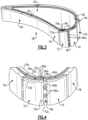
Figure 2 illustrates a perspective view of an airfoil. -
Figure 3 illustrates a sectioned view of the airfoil. -
Figure 4 illustrates a view of a leading edge region of the airfoil. -
Figure 5 illustrates an isolated view of a portion of a CMC liner. -
Figure 6 illustrates a leading end region of an airfoil without a portion of a monolithic ceramic shell. -
Figure 7 illustrates a sectioned view through ribs in the wall of an airfoil. -
Figure 1 schematically illustrates agas turbine engine 10. Theengine 10 includes acompressor section 12 and aturbine section 14 interconnected by ashaft 16. Acombustor 18 is arranged between the compressor andturbine sections 12/14. Theturbine section 14 includes first andsecond turbines 20/22, which correspond to high and low pressure turbines, respectively. Agenerator 24 is rotationally driven by a shaft coupled to thelow pressure turbine 22, or power turbine. Thegenerator 24 provides electricity to apower grid 26. It should be understood that the illustratedengine 10 is highly schematic, and may vary from the configuration illustrated. Moreover, the examples herein are not limited to industrial turbines and may be used in propulsion gas turbine engines. -
Figure 2 illustrates an isolated view of anairfoil 58 that demonstrates several aspects of the present disclosure, andFigure 3 illustrates a sectioned view of theairfoil 58. As will be appreciated, theairfoil 58 is from theturbine section 14 of theengine 10. Although theairfoil 58 is depicted as a stationary turbine vane that has radially inner and outer endwalls, it is to be understood that theairfoil 58 may alternatively be a rotating blade. As used herein, directional terms such as "axial," "radial," and the like are taken with regard to the rotational axis of theengine 10, which is generally coaxial with theshaft 16. - The
airfoil 58 is generally comprised of anairfoil section 60 that defines aleading edge 60a, a trailingedge 60b, a first orpressure side 60c, and a second or suction side 60d. The terminology "first" and "second" as used herein is to differentiate that there are two architecturally distinct components or features. It is to be further understood that the terms "first" and "second" are interchangeable in the embodiments herein in that a first component or feature could alternatively be termed as a second component or feature, and vice versa. - Referring to
Figure 3 , theairfoil section 60 is formed of anairfoil wall 62 that surrounds acore cavity 63. In this example, theairfoil section 60 includes a single cavity, although multiple cavities that are divided by ribs or other structures are also contemplated. Thecore cavity 63 is connected to a cooling air source, such as bleed air from thecompressor 12, which provides relatively cool air into thecore cavity 63 for cooling theairfoil 58. - The
airfoil wall 62 includes an exterior monolithic ceramic shell 64 (hereafter "shell 64") and an interior ceramic matrix composite liner 66 (hereafter "liner 66") that lines, and is bonded to, the interior surfaces of theshell 64. Generally theshell 64 facilitates providing good high temperature resistance and stability against oxidation, corrosion, erosion (recession), and compressive strength, and theliner 66 facilitates providing good tensile strength, and creep resistance. The combined shell and liner provide superior impact resistance. - The
shell 64 may be, but is not limited to, silicon carbide (SiC), silicon nitride (Si3N4), alumina (Al2O3), silicon aluminum oxynitride (SiAlON), nitride bonded silicon carbide (NBSC), aluminum nitride (AlN), silicon oxynitride (Si2N2O), hafnia (HfO2), zirconia (ZrO2), or other oxides, carbides, or nitrides, and particulate composites thereof. In some examples, theshell 64 has a thickness from about 0.5 millimeters to about 0.8 millimeters. - The ceramic matrix composite (CMC) of the
liner 66 includes bundles of fibers called tows in the form of yarns that can be woven into plies or laid out on unidirectional tape and disposed in a ceramic matrix. The fibers within the CMC layers include fiber bundles woven into plies, like cloth, which are assembled into a fiber-reinforced preform which is later infiltrated with the ceramic matrix. Most typically, the fibers are ceramic fibers that are provided as a fiber network, such as woven plies, fibrous mats, and the like. The fibers may be, but are not limited to, non-oxide fibers such as SiC fibers or oxide fibers such as aluminosilicate fibers. The fibers may also be coated with boron nitride (BN) or other interface material to prevent bonding with the matrix. - The ceramic matrix of the
liner 66 may be, but is not limited to, amorphous compounds of silicon, carbon, nitrogen, oxygen, boron, or other light elements. Example compounds include SiC, Al2O3, Si3N4, boron nitride (BN), SiAlON, AIN, magnesium aluminum silicate (MAS), lithium aluminum silicate, barium aluminum silicate (BAS), barium magnesium aluminum silicate (BMAS), and combinations thereof. Those skilled in the art will recognize that other matrices, including metalloids such as silicon or alloys thereof, could be employed. - As shown in the view of the leading edge region in
Figure 4 , theliner 66 includes fourfiber plies 66a/66b/66c/66d, although additional fiber plies or fewer plies may alternatively be used. In the example depicted, theply 66a is an innermost ply, theply 66d is an outermost ply, theply 66b is an inner intermediate ply, and theply 66c is an outer intermediate ply. Theplies 66a/66b/66c/66d are bonded together via the matrix of the CMC material. -
Figure 5 illustrates an isolated view of a portion of theliner 66 and plies 66a/66b/66c/66d. Theply 66d forms tabs 68 that are raised from theunderlying ply 66c so as to define aslot 70 that allows for cooling air to pass between thetabs 68 and theunderlying ply 66c. Thetabs 68 in this example are formed from thesingle ply 66d and are thus one ply thick. Thetabs 68 may alternatively be formed from twoplies 66c/66d or more than two plies for additional strength. - Each
tab 68 is generally axially elongated and includes abase 68a that projects outwards, away from theunderlying ply 66c and abody portion 68b that projects off of thebase portion 68a. Thebody portion 68b extends along theunderlying ply 66c such that theslot 70 has a relatively uniform width at thebody portion 68b. For reasons which will be evident below, atip portion 68c projects off of thebody portion 68b in a direction away from theunderlying ply 66c. Thetabs 68 are generally spaced apart from one another and are arranged in radial rows (R), as depicted inFigure 6 (Figure 6 excludes a portion of theshell 64 so that thetabs 68 are visible). In the illustrated example, there are two rows (R) oftabs 68. - Turning again to
Figure 4 , theshell 64 is made up of multiple distinct shell pieces, including afirst shell piece 72, asecond shell piece 74, athird shell piece 76, and afourth shell piece 78. In this example, the first andsecond shell pieces 72/74 form the leading edge region, while thethird shell piece 76 forms the pressure side and thefourth shell piece 78 forms the suction side. The multiple pieces may facilitate alleviating mechanical stresses and the thermal stress between different regions of theairfoil 58. Moreover, theshell pieces 72/74/76/78 are of relatively simple construction in that they do not contain any orifices, which facilitates reductions in thermal gradients and stress concentrations for enhanced damage tolerance. - The
first shell piece 72 and thesecond shell piece 74 are of similar construction to each other and while thefirst shell piece 72 is described below, thesecond shell piece 74 should be understood to include the same features. Thefirst shell piece 72 is formed of abody portion 72a and atapered flange 72b that projects (axially) off of thebody portion 72a. Thebody portion 72a is bonded to theoutermost ply 66d at interface (I), as depicted inFigure 3 . In comparison to the taperedflange 72b, thebody portion 72a is relatively thick. In the illustrated example, thebody portion 72a and theflange 72b are radially elongated. Thebody portion 72a defines aside edge 72c that has an exteriorsloped lip 72d. - The
second shell piece 74 is located adjacent thefirst shell piece 72. Together, the side edges 72c of theshell pieces 72/74 form sides of atrench 80, with theoutermost ply 66d of theliner 66 forming a floor of thetrench 80. In that regard, the floor includes a plurality oftrench orifices 80a through theliner 66 that connect thecavity 63 and thetrench 80. At least a portion of thetrench orifices 80a are sloped radially outwards, as indicated at 80b (Figure 3 ). In the illustrated example, thetrench 80 is located at theleading edge 60a of theairfoil section 60, however, it is to be understood that thetrench 80 could alternatively or additionally be located on the pressure side, the suction side, or both. - The
third shell piece 76 and thefourth shell piece 78 are of similar construction to each other and while thethird shell piece 76 is described below, thefourth shell piece 78 is understood include the same features. Thethird shell piece 76 is formed of abody portion 76a and atapered flange 76b that projects (axially) off of thebody portion 76a. In comparison to the taperedflange 76b, thebody portion 76a is relatively thick. - As best shown in
Figure 3 , theflange 76b of thethird shell piece 76 is disposed in theslot 70 under thetabs 68. Thefirst shell piece 72 overlies theouter ply 66d such that theflange 72b overlaps thetabs 68. Theflanges 72b/76b thus overlap each other, with thetabs 68 situated there between to structurally support theflange 72b of thefirst shell piece 72 as well as to allow cooling air to pass between the shell pieces. In this regard, thethird shell piece 76 is an underlapping shell piece and thefirst shell piece 72 is an overlapping shell piece. Similarly, thefourth shell piece 78 is an underlapping shell piece and thesecond shell piece 74 is an overlapping shell piece. As shown in a sectioned view inFigure 7 , theflange 72b of thefirst shell piece 72 is bonded to the top surface of thetabs 68 at interfaces (I1) and theflange 76b of thethird shell piece 76 is bonded to the inside surface of thetabs 68 at interfaces (I2). -
Channels 82 are bound byadjacent tabs 68 that serve as the channel sides and theflanges 72b/76b that serve as the respective channel top and bottom. As can be seen inFigure 6 , there are channel orifices 82a through theliner 66 that connect thechannels 82 and thecavity 63. The channel orifices 82a serve as inlets for cooling air to flow into thechannels 82. Thechannels 82 are axially elongated and generally extend from the channel orifices 82a to achannel outlet section 82b. Theoutlet section 82b is sloped relative to the surface of thethird shell piece 76. Thetip portions 68c of thetabs 68 abut and are bonded with the sloped surface portion of thethird shell piece 76 adjacent theoutlet section 82b. The slope of theoutlet section 82b is generally shallow in order to discharge a film of cooling air along the outer surface of thethird shell piece 76. In the example shown, thetabs 68 extend axially and are straight-sided, which forms thechannels 82 to be axial and straight-sided. In another example, thetabs 68 taper in width along thebody portion 68b, resulting in thechannels 82 widening with further distance from the orifices 82a in order to diffuse cooling air flow. Additionally or alternatively, thetabs 68 are tapered in thickness, such that thechannels 82 are also set back from the edge of theflanges 72b. In further examples, thetabs 68 can also have aerodynamic contours to facilitate cooling air flow and/or minimize mixing losses when the air is discharged for film cooling. - During operation of the
engine 10 cooling air is provided into thecore cavity 63. The cooling air flows through thetrench orifices 80a and cools the side edges 72c of theshell pieces 72/74. The slopedlip 72d of theside edge 72c permits the cooling air to leak out of thetrench 80 as a cooling film along the outer surface of theshell piece 72. The cooling air also flows through the channel orifices 82a into thechannels 82. The cooling air flowing in thechannels 82 cools theflanges 72b/76b and then may also be discharged as a cooling film along the outside of theshell piece 76. - The fabrication of the
shell pieces 72/74/76/78 is not particularly limited and may be produced by slip casting, isostatic pressing and green machining, injection molding, or additive manufacturing, followed by densification. Densification techniques include, but are not limited to, sintering, hot isostatic pressing (HIP), sinter-HIPing, silicon infiltration and reaction bonding, and reaction bonding in combination with other techniques listed herein. - The fabrication of the
liner 66 also is not particularly limited and may be produced using a fiber-reinforced preform and then infiltrating the preform with a ceramic matrix material or precursor to the ceramic matrix material. The infiltration may be conducted by any of a variety of methods, including but not limited to, chemical vapor infiltration (CVI), polymer infiltration and pyrolysis (PIP), transfer molding, and melt infiltration (MI). Theshell 64 may be prefabricated using known ceramic processing techniques. The preform may be constructed in the desired geometry in theshell 64, in contact with the interior surfaces of theshell 64. For example, fiber plies are built-up to construct the walls of theliner 66. Upon densification of the ceramic matrix of theliner 66, due to the contact between the preform and the monolithic ceramic of theshell 64, the ceramic matrix material strongly bonds with the monolithic ceramic. Such bonding facilitates mechanical strength in theairfoil 58 as well as heat transfer through joined interfaces between theshell 64 and theliner 66. Additionally, since theshell 64 andliner 66 are bonded together at high temperature during firing and curing, having multiple shell pieces can allow for relief of residual stresses generated during the manufacturing process. - Alternatively, the
liner 66 may be prefabricated and densified prior to bonding with theshell 64 and then assembled into theshell 64. A brazing material, such as but not limited to elemental silicon, may be provided at the interfaces that are to be joined. Upon heating to an appropriate brazing temperature for the selected brazing material, the brazing material diffuses and bonds theshell 64 andliner 66 together. - Although a combination of features is shown in the illustrated examples, not all of them need to be combined to realize the benefits of various embodiments of this disclosure. In other words, a system designed according to an embodiment of this disclosure will not necessarily include all of the features shown in any one of the Figures or all of the portions schematically shown in the Figures. Moreover, selected features of one example embodiment may be combined with selected features of other example embodiments.
- The preceding description is exemplary rather than limiting in nature. Variations and modifications to the disclosed examples may become apparent to those skilled in the art that do not necessarily depart from this disclosure. The scope of legal protection given to this disclosure can only be determined by studying the following claims.
Claims (8)
- An airfoil (58) comprising:
an airfoil section (60) having an airfoil wall (62) surrounding a cavity (63), the airfoil wall (62) including an exterior monolithic ceramic shell (64) and an interior ceramic matrix composite (CMC) liner (66) bonded with the exterior monolithic ceramic shell (64), the exterior monolithic ceramic shell (64) including a first shell piece (72) having a first side edge (72c) and a second shell piece (74) having a second side edge, the first and second side edges (72c) defining sides of an elongated trench (80) and the CMC liner (66) defining a floor of the trench (80), the floor including a plurality of orifices (80a) through the CMC liner (66) connecting the cavity (63) and the trench (80). - The airfoil (58) as recited in claim 1, wherein at least the first side edge (72c) defines an exterior sloped lip (72d) of the trench (80).
- The airfoil (58) as recited in claim 1 or 2, wherein at least a portion of the orifices (80a) are sloped radially outwards.
- The airfoil (58) as recited in any preceding claim, wherein the trench (80) is radially elongated.
- The airfoil (58) as recited in any preceding claim, wherein the CMC liner (66) includes CMC plies (66a, 66b, 66c, 66d), an outermost ply (66d) of the CMC plies (66a, 66b, 66c, 66d) forms tabs (68) that are raised from an underlying ply (66c) of the CMC plies (66a, 66b, 66c, 66d) so as to define a slot (70) between the tabs (68) and the underlying ply (66c), the exterior monolithic ceramic shell (64) includes an underlapping shell piece (76, 78) that has a portion disposed in the slot (70) and that is bonded with the tabs (68), and the first shell piece (72) extends over the tabs (68) and is bonded to the tabs (68).
- The airfoil (58) of any of claims 1 to 4, wherein:the CMC liner (66) includes CMC plies (66a, 66b, 66c, 66d);an outermost ply (66d) of the CMC plies (66a, 66b, 66c, 66d) forms a tab (68) that is raised from an underlying ply (66c) of the CMC plies (66a, 66b, 66c, 66d); andthe exterior monolithic ceramic shell (64) includes shell pieces (72, 74, 76, 78) with respective flanges (72b, 76b) that overlap each other with the tab (68) being situated between the flanges (72b, 76b), the tab (68) being bonded with the flanges (72b, 76b) so as to secure the flanges (72b, 76b) together.
- The airfoil (58) as recited in claim 6, wherein the tab (68) includes a base portion (68a) that projects outwards from the underlying ply (66c) and a body portion (68b) that projects off of the base portion (68a) along the underlying ply (66c), and wherein the tab (68), optionally, includes a tip portion (68c) that projects off of the body portion (68b) away from the underlying ply (66c).
- The airfoil (58) as recited in claim 6 or 7, wherein the tab (68) is a single one of the CMC plies (66a, 66b, 66c, 66d).
Applications Claiming Priority (2)
| Application Number | Priority Date | Filing Date | Title |
|---|---|---|---|
| US16/859,198 US11286783B2 (en) | 2020-04-27 | 2020-04-27 | Airfoil with CMC liner and multi-piece monolithic ceramic shell |
| EP21170729.4A EP3922818B1 (en) | 2020-04-27 | 2021-04-27 | Airfoil with cmc liner and multi-piece monolithc ceramic shell |
Related Parent Applications (1)
| Application Number | Title | Priority Date | Filing Date |
|---|---|---|---|
| EP21170729.4A Division EP3922818B1 (en) | 2020-04-27 | 2021-04-27 | Airfoil with cmc liner and multi-piece monolithc ceramic shell |
Publications (3)
| Publication Number | Publication Date |
|---|---|
| EP4325027A2 true EP4325027A2 (en) | 2024-02-21 |
| EP4325027A3 EP4325027A3 (en) | 2024-04-24 |
| EP4325027B1 EP4325027B1 (en) | 2025-05-28 |
Family
ID=75728584
Family Applications (2)
| Application Number | Title | Priority Date | Filing Date |
|---|---|---|---|
| EP24151047.8A Active EP4325027B1 (en) | 2020-04-27 | 2021-04-27 | Airfoil with cmc liner with multi-piece monolithic ceramic shell |
| EP21170729.4A Active EP3922818B1 (en) | 2020-04-27 | 2021-04-27 | Airfoil with cmc liner and multi-piece monolithc ceramic shell |
Family Applications After (1)
| Application Number | Title | Priority Date | Filing Date |
|---|---|---|---|
| EP21170729.4A Active EP3922818B1 (en) | 2020-04-27 | 2021-04-27 | Airfoil with cmc liner and multi-piece monolithc ceramic shell |
Country Status (2)
| Country | Link |
|---|---|
| US (1) | US11286783B2 (en) |
| EP (2) | EP4325027B1 (en) |
Citations (4)
| Publication number | Priority date | Publication date | Assignee | Title |
|---|---|---|---|---|
| EP0330601A1 (en) | 1988-01-25 | 1989-08-30 | United Technologies Corporation | Cooled gas turbine blade |
| US20100054930A1 (en) | 2008-09-04 | 2010-03-04 | Morrison Jay A | Turbine vane with high temperature capable skins |
| EP2500548A1 (en) | 2009-11-13 | 2012-09-19 | IHI Corporation | Method for producing vane |
| US20180135447A1 (en) | 2016-11-17 | 2018-05-17 | United Technologies Corporation | Airfoil with dual profile leading end |
Family Cites Families (28)
| Publication number | Priority date | Publication date | Assignee | Title |
|---|---|---|---|---|
| BE432599A (en) * | 1938-02-08 | |||
| US2585871A (en) * | 1945-10-22 | 1952-02-12 | Edward A Stalker | Turbine blade construction with provision for cooling |
| US3533711A (en) * | 1966-02-26 | 1970-10-13 | Gen Electric | Cooled vane structure for high temperature turbines |
| US3619077A (en) * | 1966-09-30 | 1971-11-09 | Gen Electric | High-temperature airfoil |
| US4026659A (en) * | 1975-10-16 | 1977-05-31 | Avco Corporation | Cooled composite vanes for turbine nozzles |
| US4565490A (en) * | 1981-06-17 | 1986-01-21 | Rice Ivan G | Integrated gas/steam nozzle |
| DE19617556A1 (en) * | 1996-05-02 | 1997-11-06 | Asea Brown Boveri | Thermally loaded blade for a turbomachine |
| US6013592A (en) * | 1998-03-27 | 2000-01-11 | Siemens Westinghouse Power Corporation | High temperature insulation for ceramic matrix composites |
| US6200092B1 (en) * | 1999-09-24 | 2001-03-13 | General Electric Company | Ceramic turbine nozzle |
| US6451416B1 (en) | 1999-11-19 | 2002-09-17 | United Technologies Corporation | Hybrid monolithic ceramic and ceramic matrix composite airfoil and method for making the same |
| US6543996B2 (en) * | 2001-06-28 | 2003-04-08 | General Electric Company | Hybrid turbine nozzle |
| GB2402715B (en) * | 2003-06-10 | 2006-06-14 | Rolls Royce Plc | Gas turbine aerofoil |
| US7011502B2 (en) * | 2004-04-15 | 2006-03-14 | General Electric Company | Thermal shield turbine airfoil |
| US7066717B2 (en) * | 2004-04-22 | 2006-06-27 | Siemens Power Generation, Inc. | Ceramic matrix composite airfoil trailing edge arrangement |
| GB0424593D0 (en) * | 2004-11-06 | 2004-12-08 | Rolls Royce Plc | A component having a film cooling arrangement |
| US7316539B2 (en) * | 2005-04-07 | 2008-01-08 | Siemens Power Generation, Inc. | Vane assembly with metal trailing edge segment |
| US7393183B2 (en) * | 2005-06-17 | 2008-07-01 | Siemens Power Generation, Inc. | Trailing edge attachment for composite airfoil |
| EP1930544A1 (en) * | 2006-10-30 | 2008-06-11 | Siemens Aktiengesellschaft | Turbine blade |
| US8105030B2 (en) * | 2008-08-14 | 2012-01-31 | United Technologies Corporation | Cooled airfoils and gas turbine engine systems involving such airfoils |
| US8109725B2 (en) * | 2008-12-15 | 2012-02-07 | United Technologies Corporation | Airfoil with wrapped leading edge cooling passage |
| US8197211B1 (en) * | 2009-09-25 | 2012-06-12 | Florida Turbine Technologies, Inc. | Composite air cooled turbine rotor blade |
| US8939728B2 (en) | 2011-06-30 | 2015-01-27 | United Technologies Corporation | Hybrid part made from monolithic ceramic skin and CMC core |
| ES2823229T3 (en) | 2014-05-09 | 2021-05-06 | Huawei Tech Co Ltd | User equipment, base station, base station access procedure and radio link supervision procedure |
| EP3153666A1 (en) | 2015-10-06 | 2017-04-12 | MTU Aero Engines GmbH | Ceramic hybrid blade for turbomachines |
| US10577942B2 (en) * | 2016-11-17 | 2020-03-03 | General Electric Company | Double impingement slot cap assembly |
| US10309226B2 (en) * | 2016-11-17 | 2019-06-04 | United Technologies Corporation | Airfoil having panels |
| US20180135427A1 (en) * | 2016-11-17 | 2018-05-17 | United Technologies Corporation | Airfoil with leading end hollow panel |
| JP6717871B2 (en) | 2018-03-14 | 2020-07-08 | 三菱重工業株式会社 | Method for manufacturing turbine blade member |
-
2020
- 2020-04-27 US US16/859,198 patent/US11286783B2/en active Active
-
2021
- 2021-04-27 EP EP24151047.8A patent/EP4325027B1/en active Active
- 2021-04-27 EP EP21170729.4A patent/EP3922818B1/en active Active
Patent Citations (4)
| Publication number | Priority date | Publication date | Assignee | Title |
|---|---|---|---|---|
| EP0330601A1 (en) | 1988-01-25 | 1989-08-30 | United Technologies Corporation | Cooled gas turbine blade |
| US20100054930A1 (en) | 2008-09-04 | 2010-03-04 | Morrison Jay A | Turbine vane with high temperature capable skins |
| EP2500548A1 (en) | 2009-11-13 | 2012-09-19 | IHI Corporation | Method for producing vane |
| US20180135447A1 (en) | 2016-11-17 | 2018-05-17 | United Technologies Corporation | Airfoil with dual profile leading end |
Also Published As
| Publication number | Publication date |
|---|---|
| US20210332705A1 (en) | 2021-10-28 |
| EP3922818A1 (en) | 2021-12-15 |
| EP3922818B1 (en) | 2024-01-10 |
| EP4325027B1 (en) | 2025-05-28 |
| EP4325027A3 (en) | 2024-04-24 |
| US11286783B2 (en) | 2022-03-29 |
Similar Documents
| Publication | Publication Date | Title |
|---|---|---|
| US11441436B2 (en) | Flow path assemblies for gas turbine engines and assembly methods therefore | |
| EP3153484B1 (en) | Ceramic matrix composite component and process of producing a ceramic matrix composite component | |
| EP3617450B1 (en) | Cmc component including directionally controllable cmc insert and method of fabrication | |
| CN113389600B (en) | Nozzle assembly with alternating guide vanes for a turbine engine | |
| US12385401B2 (en) | Ceramic matrix composite component including cooling channels and method of producing | |
| US10260358B2 (en) | Ceramic matrix composite component and process of producing a ceramic matrix composite component | |
| CA3102096C (en) | Ceramic matrix composite component and method of producing a ceramic matrix composite component | |
| EP3460193B1 (en) | Contact interface for a composite component and methods of fabrication | |
| EP3819466B1 (en) | Ceramic airfoil trailing edge configuration | |
| EP3922818B1 (en) | Airfoil with cmc liner and multi-piece monolithc ceramic shell | |
| US20210229317A1 (en) | CMC Laminate Components Having Laser Cut Features | |
| EP3929403B1 (en) | Airfoil having internally cooled wall with liner and shell | |
| US12467629B1 (en) | CMC component with cover plate |
Legal Events
| Date | Code | Title | Description |
|---|---|---|---|
| PUAI | Public reference made under article 153(3) epc to a published international application that has entered the european phase |
Free format text: ORIGINAL CODE: 0009012 |
|
| STAA | Information on the status of an ep patent application or granted ep patent |
Free format text: STATUS: THE APPLICATION HAS BEEN PUBLISHED |
|
| AC | Divisional application: reference to earlier application |
Ref document number: 3922818 Country of ref document: EP Kind code of ref document: P |
|
| AK | Designated contracting states |
Kind code of ref document: A2 Designated state(s): AL AT BE BG CH CY CZ DE DK EE ES FI FR GB GR HR HU IE IS IT LI LT LU LV MC MK MT NL NO PL PT RO RS SE SI SK SM TR |
|
| REG | Reference to a national code |
Ref legal event code: R079 Ipc: F01D0005140000 Ref country code: DE Ref legal event code: R079 Ref document number: 602021031561 Country of ref document: DE Free format text: PREVIOUS MAIN CLASS: F01D0009040000 Ipc: F01D0005140000 |
|
| PUAL | Search report despatched |
Free format text: ORIGINAL CODE: 0009013 |
|
| AK | Designated contracting states |
Kind code of ref document: A3 Designated state(s): AL AT BE BG CH CY CZ DE DK EE ES FI FR GB GR HR HU IE IS IT LI LT LU LV MC MK MT NL NO PL PT RO RS SE SI SK SM TR |
|
| RIC1 | Information provided on ipc code assigned before grant |
Ipc: F01D 9/04 20060101ALI20240319BHEP Ipc: F01D 9/02 20060101ALI20240319BHEP Ipc: F01D 5/28 20060101ALI20240319BHEP Ipc: F01D 5/14 20060101AFI20240319BHEP |
|
| STAA | Information on the status of an ep patent application or granted ep patent |
Free format text: STATUS: REQUEST FOR EXAMINATION WAS MADE |
|
| 17P | Request for examination filed |
Effective date: 20241009 |
|
| RBV | Designated contracting states (corrected) |
Designated state(s): AL AT BE BG CH CY CZ DE DK EE ES FI FR GB GR HR HU IE IS IT LI LT LU LV MC MK MT NL NO PL PT RO RS SE SI SK SM TR |
|
| GRAP | Despatch of communication of intention to grant a patent |
Free format text: ORIGINAL CODE: EPIDOSNIGR1 |
|
| STAA | Information on the status of an ep patent application or granted ep patent |
Free format text: STATUS: GRANT OF PATENT IS INTENDED |
|
| INTG | Intention to grant announced |
Effective date: 20241211 |
|
| GRAS | Grant fee paid |
Free format text: ORIGINAL CODE: EPIDOSNIGR3 |
|
| GRAA | (expected) grant |
Free format text: ORIGINAL CODE: 0009210 |
|
| STAA | Information on the status of an ep patent application or granted ep patent |
Free format text: STATUS: THE PATENT HAS BEEN GRANTED |
|
| AC | Divisional application: reference to earlier application |
Ref document number: 3922818 Country of ref document: EP Kind code of ref document: P |
|
| AK | Designated contracting states |
Kind code of ref document: B1 Designated state(s): AL AT BE BG CH CY CZ DE DK EE ES FI FR GB GR HR HU IE IS IT LI LT LU LV MC MK MT NL NO PL PT RO RS SE SI SK SM TR |
|
| REG | Reference to a national code |
Ref country code: GB Ref legal event code: FG4D |
|
| REG | Reference to a national code |
Ref country code: CH Ref legal event code: EP |
|
| REG | Reference to a national code |
Ref country code: DE Ref legal event code: R096 Ref document number: 602021031561 Country of ref document: DE |
|
| REG | Reference to a national code |
Ref country code: IE Ref legal event code: FG4D |
|
| REG | Reference to a national code |
Ref country code: NL Ref legal event code: MP Effective date: 20250528 |
|
| PG25 | Lapsed in a contracting state [announced via postgrant information from national office to epo] |
Ref country code: FI Free format text: LAPSE BECAUSE OF FAILURE TO SUBMIT A TRANSLATION OF THE DESCRIPTION OR TO PAY THE FEE WITHIN THE PRESCRIBED TIME-LIMIT Effective date: 20250528 Ref country code: ES Free format text: LAPSE BECAUSE OF FAILURE TO SUBMIT A TRANSLATION OF THE DESCRIPTION OR TO PAY THE FEE WITHIN THE PRESCRIBED TIME-LIMIT Effective date: 20250528 |
|
| REG | Reference to a national code |
Ref country code: LT Ref legal event code: MG9D |
|
| PG25 | Lapsed in a contracting state [announced via postgrant information from national office to epo] |
Ref country code: NO Free format text: LAPSE BECAUSE OF FAILURE TO SUBMIT A TRANSLATION OF THE DESCRIPTION OR TO PAY THE FEE WITHIN THE PRESCRIBED TIME-LIMIT Effective date: 20250828 Ref country code: GR Free format text: LAPSE BECAUSE OF FAILURE TO SUBMIT A TRANSLATION OF THE DESCRIPTION OR TO PAY THE FEE WITHIN THE PRESCRIBED TIME-LIMIT Effective date: 20250829 |
|
| PG25 | Lapsed in a contracting state [announced via postgrant information from national office to epo] |
Ref country code: NL Free format text: LAPSE BECAUSE OF FAILURE TO SUBMIT A TRANSLATION OF THE DESCRIPTION OR TO PAY THE FEE WITHIN THE PRESCRIBED TIME-LIMIT Effective date: 20250528 Ref country code: PL Free format text: LAPSE BECAUSE OF FAILURE TO SUBMIT A TRANSLATION OF THE DESCRIPTION OR TO PAY THE FEE WITHIN THE PRESCRIBED TIME-LIMIT Effective date: 20250528 |
|
| PG25 | Lapsed in a contracting state [announced via postgrant information from national office to epo] |
Ref country code: BG Free format text: LAPSE BECAUSE OF FAILURE TO SUBMIT A TRANSLATION OF THE DESCRIPTION OR TO PAY THE FEE WITHIN THE PRESCRIBED TIME-LIMIT Effective date: 20250528 |
|
| PG25 | Lapsed in a contracting state [announced via postgrant information from national office to epo] |
Ref country code: HR Free format text: LAPSE BECAUSE OF FAILURE TO SUBMIT A TRANSLATION OF THE DESCRIPTION OR TO PAY THE FEE WITHIN THE PRESCRIBED TIME-LIMIT Effective date: 20250528 |
|
| PG25 | Lapsed in a contracting state [announced via postgrant information from national office to epo] |
Ref country code: RS Free format text: LAPSE BECAUSE OF FAILURE TO SUBMIT A TRANSLATION OF THE DESCRIPTION OR TO PAY THE FEE WITHIN THE PRESCRIBED TIME-LIMIT Effective date: 20250828 |
|
| PG25 | Lapsed in a contracting state [announced via postgrant information from national office to epo] |
Ref country code: IS Free format text: LAPSE BECAUSE OF FAILURE TO SUBMIT A TRANSLATION OF THE DESCRIPTION OR TO PAY THE FEE WITHIN THE PRESCRIBED TIME-LIMIT Effective date: 20250928 |
|
| PG25 | Lapsed in a contracting state [announced via postgrant information from national office to epo] |
Ref country code: LV Free format text: LAPSE BECAUSE OF FAILURE TO SUBMIT A TRANSLATION OF THE DESCRIPTION OR TO PAY THE FEE WITHIN THE PRESCRIBED TIME-LIMIT Effective date: 20250528 |
|
| REG | Reference to a national code |
Ref country code: AT Ref legal event code: MK05 Ref document number: 1798699 Country of ref document: AT Kind code of ref document: T Effective date: 20250528 |
|
| PG25 | Lapsed in a contracting state [announced via postgrant information from national office to epo] |
Ref country code: SM Free format text: LAPSE BECAUSE OF FAILURE TO SUBMIT A TRANSLATION OF THE DESCRIPTION OR TO PAY THE FEE WITHIN THE PRESCRIBED TIME-LIMIT Effective date: 20250528 Ref country code: DK Free format text: LAPSE BECAUSE OF FAILURE TO SUBMIT A TRANSLATION OF THE DESCRIPTION OR TO PAY THE FEE WITHIN THE PRESCRIBED TIME-LIMIT Effective date: 20250528 Ref country code: AT Free format text: LAPSE BECAUSE OF FAILURE TO SUBMIT A TRANSLATION OF THE DESCRIPTION OR TO PAY THE FEE WITHIN THE PRESCRIBED TIME-LIMIT Effective date: 20250528 |
|
| PG25 | Lapsed in a contracting state [announced via postgrant information from national office to epo] |
Ref country code: CZ Free format text: LAPSE BECAUSE OF FAILURE TO SUBMIT A TRANSLATION OF THE DESCRIPTION OR TO PAY THE FEE WITHIN THE PRESCRIBED TIME-LIMIT Effective date: 20250528 |
|
| PG25 | Lapsed in a contracting state [announced via postgrant information from national office to epo] |
Ref country code: EE Free format text: LAPSE BECAUSE OF FAILURE TO SUBMIT A TRANSLATION OF THE DESCRIPTION OR TO PAY THE FEE WITHIN THE PRESCRIBED TIME-LIMIT Effective date: 20250528 |
|
| PG25 | Lapsed in a contracting state [announced via postgrant information from national office to epo] |
Ref country code: SK Free format text: LAPSE BECAUSE OF FAILURE TO SUBMIT A TRANSLATION OF THE DESCRIPTION OR TO PAY THE FEE WITHIN THE PRESCRIBED TIME-LIMIT Effective date: 20250528 |
|
| PG25 | Lapsed in a contracting state [announced via postgrant information from national office to epo] |
Ref country code: IT Free format text: LAPSE BECAUSE OF FAILURE TO SUBMIT A TRANSLATION OF THE DESCRIPTION OR TO PAY THE FEE WITHIN THE PRESCRIBED TIME-LIMIT Effective date: 20250528 |
|
| REG | Reference to a national code |
Ref country code: DE Ref legal event code: R097 Ref document number: 602021031561 Country of ref document: DE |
|
| PLBE | No opposition filed within time limit |
Free format text: ORIGINAL CODE: 0009261 |
|
| STAA | Information on the status of an ep patent application or granted ep patent |
Free format text: STATUS: NO OPPOSITION FILED WITHIN TIME LIMIT |
|
| PGFP | Annual fee paid to national office [announced via postgrant information from national office to epo] |
Ref country code: GB Payment date: 20260320 Year of fee payment: 6 |
|
| REG | Reference to a national code |
Ref country code: CH Ref legal event code: L10 Free format text: ST27 STATUS EVENT CODE: U-0-0-L10-L00 (AS PROVIDED BY THE NATIONAL OFFICE) Effective date: 20260409 |
|
| PGFP | Annual fee paid to national office [announced via postgrant information from national office to epo] |
Ref country code: FR Payment date: 20260320 Year of fee payment: 6 |