EP2500548A1 - Method for producing vane - Google Patents
Method for producing vane Download PDFInfo
- Publication number
- EP2500548A1 EP2500548A1 EP10830023A EP10830023A EP2500548A1 EP 2500548 A1 EP2500548 A1 EP 2500548A1 EP 10830023 A EP10830023 A EP 10830023A EP 10830023 A EP10830023 A EP 10830023A EP 2500548 A1 EP2500548 A1 EP 2500548A1
- Authority
- EP
- European Patent Office
- Prior art keywords
- vane
- ply
- woven
- fiber
- formed body
- Prior art date
- Legal status (The legal status is an assumption and is not a legal conclusion. Google has not performed a legal analysis and makes no representation as to the accuracy of the status listed.)
- Withdrawn
Links
Images


Classifications
-
- F—MECHANICAL ENGINEERING; LIGHTING; HEATING; WEAPONS; BLASTING
- F04—POSITIVE - DISPLACEMENT MACHINES FOR LIQUIDS; PUMPS FOR LIQUIDS OR ELASTIC FLUIDS
- F04D—NON-POSITIVE-DISPLACEMENT PUMPS
- F04D29/00—Details, component parts, or accessories
- F04D29/26—Rotors specially for elastic fluids
- F04D29/32—Rotors specially for elastic fluids for axial flow pumps
- F04D29/321—Rotors specially for elastic fluids for axial flow pumps for axial flow compressors
- F04D29/324—Blades
-
- B—PERFORMING OPERATIONS; TRANSPORTING
- B29—WORKING OF PLASTICS; WORKING OF SUBSTANCES IN A PLASTIC STATE IN GENERAL
- B29C—SHAPING OR JOINING OF PLASTICS; SHAPING OF MATERIAL IN A PLASTIC STATE, NOT OTHERWISE PROVIDED FOR; AFTER-TREATMENT OF THE SHAPED PRODUCTS, e.g. REPAIRING
- B29C70/00—Shaping composites, i.e. plastics material comprising reinforcements, fillers or preformed parts, e.g. inserts
- B29C70/04—Shaping composites, i.e. plastics material comprising reinforcements, fillers or preformed parts, e.g. inserts comprising reinforcements only, e.g. self-reinforcing plastics
- B29C70/28—Shaping operations therefor
- B29C70/30—Shaping by lay-up, i.e. applying fibres, tape or broadsheet on a mould, former or core; Shaping by spray-up, i.e. spraying of fibres on a mould, former or core
- B29C70/302—Details of the edges of fibre composites, e.g. edge finishing or means to avoid delamination
-
- B—PERFORMING OPERATIONS; TRANSPORTING
- B29—WORKING OF PLASTICS; WORKING OF SUBSTANCES IN A PLASTIC STATE IN GENERAL
- B29D—PRODUCING PARTICULAR ARTICLES FROM PLASTICS OR FROM SUBSTANCES IN A PLASTIC STATE
- B29D99/00—Subject matter not provided for in other groups of this subclass
- B29D99/0025—Producing blades or the like, e.g. blades for turbines, propellers, or wings
- B29D99/0028—Producing blades or the like, e.g. blades for turbines, propellers, or wings hollow blades
-
- F—MECHANICAL ENGINEERING; LIGHTING; HEATING; WEAPONS; BLASTING
- F01—MACHINES OR ENGINES IN GENERAL; ENGINE PLANTS IN GENERAL; STEAM ENGINES
- F01D—NON-POSITIVE DISPLACEMENT MACHINES OR ENGINES, e.g. STEAM TURBINES
- F01D5/00—Blades; Blade-carrying members; Heating, heat-insulating, cooling or antivibration means on the blades or the members
- F01D5/12—Blades
- F01D5/14—Form or construction
- F01D5/18—Hollow blades, i.e. blades with cooling or heating channels or cavities; Heating, heat-insulating or cooling means on blades
- F01D5/187—Convection cooling
-
- F—MECHANICAL ENGINEERING; LIGHTING; HEATING; WEAPONS; BLASTING
- F01—MACHINES OR ENGINES IN GENERAL; ENGINE PLANTS IN GENERAL; STEAM ENGINES
- F01D—NON-POSITIVE DISPLACEMENT MACHINES OR ENGINES, e.g. STEAM TURBINES
- F01D5/00—Blades; Blade-carrying members; Heating, heat-insulating, cooling or antivibration means on the blades or the members
- F01D5/12—Blades
- F01D5/28—Selecting particular materials; Particular measures relating thereto; Measures against erosion or corrosion
- F01D5/282—Selecting composite materials, e.g. blades with reinforcing filaments
-
- F—MECHANICAL ENGINEERING; LIGHTING; HEATING; WEAPONS; BLASTING
- F01—MACHINES OR ENGINES IN GENERAL; ENGINE PLANTS IN GENERAL; STEAM ENGINES
- F01D—NON-POSITIVE DISPLACEMENT MACHINES OR ENGINES, e.g. STEAM TURBINES
- F01D5/00—Blades; Blade-carrying members; Heating, heat-insulating, cooling or antivibration means on the blades or the members
- F01D5/12—Blades
- F01D5/28—Selecting particular materials; Particular measures relating thereto; Measures against erosion or corrosion
- F01D5/284—Selection of ceramic materials
-
- F—MECHANICAL ENGINEERING; LIGHTING; HEATING; WEAPONS; BLASTING
- F04—POSITIVE - DISPLACEMENT MACHINES FOR LIQUIDS; PUMPS FOR LIQUIDS OR ELASTIC FLUIDS
- F04D—NON-POSITIVE-DISPLACEMENT PUMPS
- F04D29/00—Details, component parts, or accessories
- F04D29/02—Selection of particular materials
- F04D29/023—Selection of particular materials especially adapted for elastic fluid pumps
-
- F—MECHANICAL ENGINEERING; LIGHTING; HEATING; WEAPONS; BLASTING
- F04—POSITIVE - DISPLACEMENT MACHINES FOR LIQUIDS; PUMPS FOR LIQUIDS OR ELASTIC FLUIDS
- F04D—NON-POSITIVE-DISPLACEMENT PUMPS
- F04D29/00—Details, component parts, or accessories
- F04D29/26—Rotors specially for elastic fluids
- F04D29/32—Rotors specially for elastic fluids for axial flow pumps
- F04D29/38—Blades
- F04D29/388—Blades characterised by construction
-
- F—MECHANICAL ENGINEERING; LIGHTING; HEATING; WEAPONS; BLASTING
- F05—INDEXING SCHEMES RELATING TO ENGINES OR PUMPS IN VARIOUS SUBCLASSES OF CLASSES F01-F04
- F05D—INDEXING SCHEME FOR ASPECTS RELATING TO NON-POSITIVE-DISPLACEMENT MACHINES OR ENGINES, GAS-TURBINES OR JET-PROPULSION PLANTS
- F05D2230/00—Manufacture
- F05D2230/60—Assembly methods
- F05D2230/68—Assembly methods using auxiliary equipment for lifting or holding
-
- F—MECHANICAL ENGINEERING; LIGHTING; HEATING; WEAPONS; BLASTING
- F05—INDEXING SCHEMES RELATING TO ENGINES OR PUMPS IN VARIOUS SUBCLASSES OF CLASSES F01-F04
- F05D—INDEXING SCHEME FOR ASPECTS RELATING TO NON-POSITIVE-DISPLACEMENT MACHINES OR ENGINES, GAS-TURBINES OR JET-PROPULSION PLANTS
- F05D2240/00—Components
- F05D2240/10—Stators
- F05D2240/12—Fluid guiding means, e.g. vanes
- F05D2240/122—Fluid guiding means, e.g. vanes related to the trailing edge of a stator vane
-
- F—MECHANICAL ENGINEERING; LIGHTING; HEATING; WEAPONS; BLASTING
- F05—INDEXING SCHEMES RELATING TO ENGINES OR PUMPS IN VARIOUS SUBCLASSES OF CLASSES F01-F04
- F05D—INDEXING SCHEME FOR ASPECTS RELATING TO NON-POSITIVE-DISPLACEMENT MACHINES OR ENGINES, GAS-TURBINES OR JET-PROPULSION PLANTS
- F05D2240/00—Components
- F05D2240/20—Rotors
- F05D2240/30—Characteristics of rotor blades, i.e. of any element transforming dynamic fluid energy to or from rotational energy and being attached to a rotor
- F05D2240/304—Characteristics of rotor blades, i.e. of any element transforming dynamic fluid energy to or from rotational energy and being attached to a rotor related to the trailing edge of a rotor blade
-
- F—MECHANICAL ENGINEERING; LIGHTING; HEATING; WEAPONS; BLASTING
- F05—INDEXING SCHEMES RELATING TO ENGINES OR PUMPS IN VARIOUS SUBCLASSES OF CLASSES F01-F04
- F05D—INDEXING SCHEME FOR ASPECTS RELATING TO NON-POSITIVE-DISPLACEMENT MACHINES OR ENGINES, GAS-TURBINES OR JET-PROPULSION PLANTS
- F05D2300/00—Materials; Properties thereof
- F05D2300/60—Properties or characteristics given to material by treatment or manufacturing
- F05D2300/603—Composites; e.g. fibre-reinforced
- F05D2300/6033—Ceramic matrix composites [CMC]
-
- Y—GENERAL TAGGING OF NEW TECHNOLOGICAL DEVELOPMENTS; GENERAL TAGGING OF CROSS-SECTIONAL TECHNOLOGIES SPANNING OVER SEVERAL SECTIONS OF THE IPC; TECHNICAL SUBJECTS COVERED BY FORMER USPC CROSS-REFERENCE ART COLLECTIONS [XRACs] AND DIGESTS
- Y02—TECHNOLOGIES OR APPLICATIONS FOR MITIGATION OR ADAPTATION AGAINST CLIMATE CHANGE
- Y02T—CLIMATE CHANGE MITIGATION TECHNOLOGIES RELATED TO TRANSPORTATION
- Y02T50/00—Aeronautics or air transport
- Y02T50/60—Efficient propulsion technologies, e.g. for aircraft
-
- Y—GENERAL TAGGING OF NEW TECHNOLOGICAL DEVELOPMENTS; GENERAL TAGGING OF CROSS-SECTIONAL TECHNOLOGIES SPANNING OVER SEVERAL SECTIONS OF THE IPC; TECHNICAL SUBJECTS COVERED BY FORMER USPC CROSS-REFERENCE ART COLLECTIONS [XRACs] AND DIGESTS
- Y10—TECHNICAL SUBJECTS COVERED BY FORMER USPC
- Y10T—TECHNICAL SUBJECTS COVERED BY FORMER US CLASSIFICATION
- Y10T156/00—Adhesive bonding and miscellaneous chemical manufacture
- Y10T156/10—Methods of surface bonding and/or assembly therefor
Definitions
- the present invention relates to a method for manufacturing a vane to be used in a turbine or a compressor of a gas turbine engine such as a jet engine.
- a turbine vane (including a turbine stator vane and a turbine rotor blade) used in a turbine of a jet engine is generally constituted of heat-resistant alloy such as nickel alloy. Meanwhile, composite material such as ceramic matrix composite (CMC) that has superior heat-resistance property to nickel alloy and lower density than nickel alloy recently draws attention.
- CMC turbine vane A turbine blade constituted of ceramic matrix composite (CMC turbine vane) has also been developed (see Patent Documents 1 and 2 listed below). And a CMC turbine vane is manufactured according to a following method.
- ceramic fiber (fiber bundle of ceramic fiber) is woven two-dimensionally and/or three-dimensionally along a surface of the jig.
- a woven-fiber formed body constituted of ceramic fiber is formed on a surface of the jig.
- an infiltration method such as Chemical Vapor Infiltration (CVI) or Polymer Impregnation and Pyrolysis (PIP)
- CVI Chemical Vapor Infiltration
- PIP Polymer Impregnation and Pyrolysis
- ceramic matrix is infiltrated into the woven-fiber formed body.
- the infiltrated woven-fiber formed body is treated with a machining process and so on, and thereby a CMC turbine vane is manufactured.
- a CMC turbine vane is needed to be thicker as a whole than a turbine vane made of heat-resistant alloy in order to secure rigidity of the CMC turbine vane.
- a trailing edge of the turbine vane is subject to be thick. Meanwhile, if a trailing edge of a turbine vane is thick, mixture loss of swirls generated near the trailing edge of the turbine vane and a main flow increases. As a result, pressure loss increases and thereby it becomes difficult to improve turbine efficiency.
- An object of the present invention is to provide a method for manufacturing a vane that can improve turbine efficiency by reducing thickness of a trailing edge of the vane.
- any of following aspects of the present invention relates to manufacturing of a vane that is to be used in a turbine or a compressor of a gas turbine engine and made of composite material constituted of reinforcement fiber and matrix, and comprises; an outer ply vane that is made of composite material constituted of reinforcement fiber and matrix; and an inner ply vane that is made of composite material constituted of reinforcement fiber and matrix, and extends from an inner surface of the outer ply vane on a leading-edge side toward an inner surface of the outer ply vane on a trailing-edge side, a convex-side outer surface thereof being stuck integrally with a convex-side inner surface of the outer ply vane, and a concave-side outer surface thereof being stuck integrally with a concave-side inner surface of the outer ply vane; wherein a rear space is segmented within the outer ply vane between an outer surface of the inner ply vane on the trailing-edge side and an inner surface of the outer ply vane
- a first aspect of the present invention provides a method for manufacturing the above vane that comprises: (a) forming an inner ply vane woven-fiber formed body constituted of reinforcement fiber on a surface of a jig that has a surface profile corresponding to an inner surface profile of the inner ply vane; (b) infiltrating matrix into the inner ply vane woven-fiber formed body to turn the inner ply vane woven-fiber formed body into the inner ply vane; (c), during or after (b), removing the jig away from the inner ply vane woven-fiber formed body or the inner ply vane; (d), after (b) and (c), integrating a supplemental jig that has a surface profile corresponding to the rear space and the inner ply vane to form a integrated body; (e), after (d), forming an outer ply vane woven-fiber formed body constituted of reinforcement fiber on a surface of the integrated body; (f), after (e), in
- a second aspect of the present invention provides a method for manufacturing the above vane that comprises: (A) forming an inner ply vane woven-fiber formed body constituted of reinforcement fiber on a surface of a jig that has a surface profile corresponding to an inner surface profile of the inner ply vane; (B), after (A), integrating a supplemental jig that has a surface profile corresponding to the rear space and the inner ply vane woven-fiber formed body to form a integrated body; (C), after (B), forming an outer ply vane woven-fiber formed body constituted of reinforcement fiber on a surface of the integrated body; (D), after (C), infiltrating matrix into the inner ply vane woven-fiber formed body and the outer ply vane woven-fiber formed body to turn the inner ply vane woven-fiber formed body and the outer ply vane woven-fiber formed body into the inner ply vane and the outer ply vane, respectively; and (E),
- a third aspect of the present invention provides a method for manufacturing the above vane that comprises: (i) forming an inner ply vane woven-fiber formed body constituted of reinforcement fiber on a surface of a jig that has a surface profile corresponding to an inner surface profile of the inner ply vane; (ii) infiltrating matrix into the inner ply vane woven-fiber formed body to turn the inner ply vane woven-fiber formed body into the inner ply vane; (iii), during or after (ii), removing the jig away from the inner ply vane woven-fiber formed body or the inner ply vane; (iv), after (ii) and (iii), integrating a rear filled member that has a surface profile corresponding to the rear space and the inner ply vane to form a integrated body; (v), after (iv), forming an outer ply vane woven-fiber formed body constituted of reinforcement fiber on a surface of the integrated body; and (
- a fourth aspect of the present invention provides a method for manufacturing the above vane that comprises: (I) forming an inner ply vane woven-fiber formed body constituted of reinforcement fiber on a surface of a jig that has a surface profile corresponding to an inner surface profile of the inner ply vane; (II), after (I), integrating a rear filled member that has a surface profile corresponding to the rear space and the inner ply vane woven-fiber formed body to form a integrated body; (III), after (II), forming an outer ply vane woven-fiber formed body constituted of reinforcement fiber on a surface of the integrated body; (IV), after (III), infiltrating matrix into the inner ply vane woven-fiber formed body and the outer ply vane woven-fiber formed body to turn the inner ply vane woven-fiber formed body and the outer ply vane woven-fiber formed body into the inner ply vane and the outer ply vane, respectively; and (V), during
- the composite material is ceramic matrix composite or carbon-based composite material. Since ceramic matrix composite or carbon-based composite material has higher heatproof temperature than metal, cooling of the vane under high temperature environment can be eliminated or cooling air volume can be reduced and the efficiency can be improved. In addition, since ceramic matrix composite or carbon-based composite material has lower density than metal and can reduce component weight, weight reduction can be achieved and fuel consumption rate can be improved.
- a term “vane” includes a “turbine vane” and a “compressor vane”.
- a term “turbine vane” includes a “turbine stator vane” and a “turbine rotor blade”.
- a term “compressor vane” includes a “compressor stator vane” and a “compressor rotor blade”.
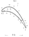
- a turbine stator vane 3 manufactured by after-described embodiments of a manufacturing method will be explained with reference to Figs. 1 and 2 .
- an "F” indicates a forward direction (an upstream direction)
- an “R” in the drawings indicates a rearward direction (a downstream direction)
- an "In” indicates a radially-inward direction
- an “Out” indicates a radially-outward direction.
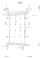
- a turbine stator (turbine nozzle) used in a turbine (not shown) of a jet engine is segmented into plural turbine stator segments (turbine nozzle segments) 1 along its circumferential direction (see Fig. 2 ).
- the turbine stator segment 1 includes plural turbine stator vanes 3 (only one of them is shown).
- the turbine stator vane 3 is constituted of Ceramic Matrix Composites (a type of composite materials, hereinafter referred to as CMC) that is made of ceramic matrix (a type of matrixes) and ceramic fiber (a type of reinforcement fibers). Note that a detail constitution of the turbine stator vane 3 will be described later.
- An arch-shaped outer band 5 is provided integrally on an outer end (radially outer end) of the turbine stator vane 3.
- the outer band 5 is constituted of heat-resistant alloy such as nickel alloy.
- an arch-shaped front flange 7 that is to be engaged with a portion of a turbine case (not shown) is formed on a front side of the outer band 5.
- an arch-shaped rear flange 9 that is to be engaged with a portion of the turbine case is formed on a rear side of the outer band 5.
- the outer band 5 may be constituted of composite materials such as CMC and carbon-based composite materials instead of heat-resistant alloy.
- An arch-shaped inner band 11 is provided integrally on an inner end (radially inner end) of the turbine stator vane 3.
- the inner band 11 is constituted of heat-resistant alloy such as nickel alloy.
- an arch-shaped rib 13 that is to be fit with a groove (not shown) on a stator support member integrally coupled with the turbine case.
- the inner band 11 may be constituted of composite materials such as CMC and carbon-based composite materials instead of heat-resistant alloy.
- the turbine stator vane 3 includes a hollow outer ply vane (an outer vane) 15.
- the outer ply vane 15 is constituted of CMC that is made of ceramic fiber and ceramic matrix.
- CMC ceramic fiber and ceramic matrix.
- carbon fiber, glass fiber or blending fiber of these blending fiber made of two or more kinds of ceramic fiber, carbon fiber and glass fiber
- carbon matrix or glass matrix may be used instead of ceramic matrix.
- An inner ply vane (inner vane) 17 is provided integrally on an inner surface of the outer ply vane 15.
- the inner ply vane 17 is constituted of CMC that is made of ceramic fiber and ceramic matrix.
- the inner ply vane 17 extends from an inner surface 15a of the outer ply vane 15 on a leading-edge side toward an inner surface 15t of the outer ply vane 15 on a trailing-edge side.
- An outer surface 17t of the inner ply vane 17 on the trailing-edge side is positioned nearer to the trailing-edge side than a middle position (middle position along a chord length) of the inner ply vane 17.
- an outer surface 17d of the inner ply vane 17 on a convex-side is stuck integrally with a convex-side inner surface 15d of the outer ply vane 15.
- an outer surface 17v of the inner ply vane 17 on a concave-side is stuck integrally with a concave-side inner surface 15v of the outer ply vane 15.
- carbon fiber, glass fiber or blending fiber of these may be used instead of ceramic fiber.
- carbon matrix or glass matrix may be used instead of ceramic matrix.
- a rear space S is segmented within the outer ply vane 15 between the outer surface 17t of the inner ply vane 17 on the trailing-edge side and the inner surface 15t of the outer ply vane 15 on the trailing-edge side.
- Plural outlet holes 19 are formed on a leading edge 3a and a concave surface 3v of the turbine stator vane 3 to inject cooling air introduced into an inside of the inner ply vane 17 through a front insert (not shown). Each of the outlet holes 19 penetrates the outer ply vane 15 and the inner ply vane 17.
- plural eduction holes 21 are formed on a trailing edge 3t of the turbine stator vane 3 to discharge cooling air introduced into an inside of the rear space S through a rear insert (not shown) . Each of the eduction holes 21 penetrates the outer ply vane 15. Note that the cooling air is compressed air extracted from a compressor (not shown) of the jet engine.
- the hollow inner ply vane 17 is integrally provided on the inner surface of the hollow outer ply vane 15, and the rear space S is segmented between the outer surface 17t of the inner ply vane 17 on the trailing-edge side and the inner surface 15t of the inner ply vane 15 on the trailing-edge side. Therefore, a portion of the turbine stator vane 3 from the leading edge 3a to an intermediate position 3m (i.e. just anterior to the inner surface 15t of the inner ply vane 15 on the trailing-edge side) constructs a double ply structure with the outer ply vane 15 and the inner ply vane 17.
- a portion from the intermediate position 3m to the trailing edge 3t constructs a single ply structure only with the outer ply vane 15.
- the portion from the leading edge 3a to the intermediate position 3m in the turbine stator vane 3 made of CMC can be made thick and the portion from the intermediate position 3m to the trailing edge 3t can be made thin.
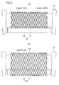
- a turbine stator vane 23 is used in a turbine of a jet engine, and schematically has the same configurations as those of the above-explained turbine stator vane 3. Only different points from the specific configurations of the turbine stator vane 3 will be explained among the specific configurations of the turbine stator vane 23. Note that the configurations of the turbine stator vane 23 identical or similar to the configurations of the turbine stator vane 3 will be indicated by identical reference numerals in the drawings and their explanations will be avoided.
- the rear space S is filled with a rear filled member (rear core member) 25.
- the rear filled member 25 is provided integrally with the outer ply vane 15 and the inner ply vane 17.
- Plural outlet holes 27 are formed on a leading edge 23a and a concave surface 23v of the turbine stator vane 23 to inject cooling air introduced into the inside of the inner ply vane 17 through the front insert (not shown).
- Each of the outlet holes 27 penetrates the outer ply vane 15 and the inner ply vane 17.
- plural eduction holes 29 are formed on a trailing edge 23t of the turbine stator vane 23 to discharge the cooling air introduced into the inside of the rear space S through the rear insert (not shown).
- Each of the eduction holes 29 penetrates the outer ply vane 15, the rear filled member 25 and the inner ply vane 17.
- the turbine stator vane 23 can also bring the same advantages as the above-explained turbine stator vane 3.
- the rear space S of the above-explained turbine stator vane 3 is filled with the rear filled member 25.
- Strength and rigidity of vane trailing edge portion of the turbine stator vane 23 can be improved by filling of the rear filled member 25.
- a method for manufacturing a turbine stator vane according to a first embodiment will be explained with reference to a flow chart shown in Fig. 4 and Figs. 5(a) to 7(b) .
- the method for manufacturing a turbine stator vane according to the present embodiment is a method for manufacturing the turbine stator vane 3 shown in Fig. 1 .
- the present method includes an inner ply vane woven-fiber forming process, an inner ply vane infiltration process, a jig removal process, an integrating process, an outer ply vane woven-fiber forming process, an outer ply vane infiltration process, a supplemental jig removal process, and a machining process.
- ceramic fiber fiber bundle of ceramic fiber
- an inner ply vane woven-fiber formed body 17F constituted of ceramic fiber is formed on the surface of the jig 31. Note that arbitrary changes can be applied to a weave style of the ceramic fiber.
- Fig. 5 (b) after the inner ply vane woven-fiber forming process, ceramic matrix is infiltrated into the inner ply vane woven-fiber formed body 17F by a Chemical Vapor Infiltration method (CVI method), a Polymer Impregnation and Pyrolysis method (PIP method), a Solid Phase Infiltration method and so on.
- CVI method Chemical Vapor Infiltration method
- PIP method Polymer Impregnation and Pyrolysis method
- Solid Phase Infiltration method Solid Phase Infiltration method
- the jig 31 is moved laterally, so that the jig 31 is removed away from the inner ply vane woven-fiber formed body 17F or the inner ply vane 17.
- a supplemental jig 33 that has a surface profile corresponding to the rear space S and the inner ply vane 17 are set to their prescribed positions on an integrating jig 37.
- the inner ply vane 17 and the supplemental jig 33 are adjacently integrated.
- ceramic fiber fiber bundle of ceramic fiber
- an outer ply vane woven-fiber formed body 15F constituted of ceramic fiber is formed on the surface of the integrated body 35.
- the outer ply vane woven-fiber formed body 15F may be formed by winding woven-fiber made of ceramic fiber on the surface of the integrated body 35 instead of by weaving the ceramic fiber.
- Fig. 7 (a) after the outer ply vane woven-fiber forming process, ceramic matrix is infiltrated into the outer ply vane woven-fiber formed body 15F by a Chemical Vapor Infiltration method (CVI method), a Polymer Impregnation and Pyrolysis method (PIP method), a Solid Phase Infiltration method and so on.
- CVI method Chemical Vapor Infiltration method
- PIP method Polymer Impregnation and Pyrolysis method
- Solid Phase Infiltration method Solid Phase Infiltration method
- the supplemental jig 33 is moved laterally, so that the supplemental jig 33 is removed away from the outer ply vane woven-fiber formed body 15F or the outer ply vane 15.
- the outlet holes 19 and the eduction holes 21 are formed by a machining process. Note that it is preferable that a coating process may be treated on surfaces of the outer ply vane 15 and the inner ply vane 17 by an arbitrary infiltration method after forming the outlet holes 19 and the eduction holes 21.
- the turbine stator vane 3 made of CMC is manufactured in this manner.
- the integrated body 35 is formed by the supplemental jig 33 that has the surface profile corresponding to the rear space S and the inner ply vane 17, and the outer ply vane woven-fiber formed body 15F is formed on the surface of the integrated body 35. Therefore, the portion of the turbine stator vane 3 from the leading edge 3a to the intermediate position 3m (i.e. just anterior to the inner surface 15t of the inner ply vane 15 on the trailing-edge side) constructs a double ply structure with the outer ply vane 15 and the inner ply vane 17. The portion from the intermediate position 3m to the trailing edge 3t constructs a single ply structure only with the outer ply vane 15. As a result, the portion from the leading edge 3a to the intermediate position 3m in the turbine stator vane 3 made of CMC can be made thick and the portion from the intermediate position 3m to the trailing edge 3t can be made thin.
- the first embodiment can bring the same advantages as the above-explained turbine stator vane 3.
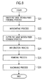
- a method for manufacturing a turbine stator vane according to a second embodiment will be explained with reference to a flow chart shown in Fig. 8 , Fig. 5(a) and Figs. 9(a) to 10(b) .
- the method for manufacturing a turbine stator vane according to the present embodiment is a method for manufacturing the turbine stator vane 3 shown in Fig. 1 .
- the present method includes an inner ply vane woven-fiber forming process, an integrating process, an outer ply vane woven-fiber forming process, an infiltration process, a removal process, and a machining process. Then, specific workings in the processes in the manufacturing method according to the present embodiment are presented as follows.
- an inner ply vane woven-fiber formed body 17F constituted of ceramic fiber is formed on a surface of a jig 31.
- a supplemental jig 33 that has a surface profile corresponding to the rear space S and the inner ply vane woven-fiber formed body 17F are adjacently integrated.
- an integrated body 35F composed of the inner ply vane woven-fiber formed body 17F and the supplemental jig 33 is formed.
- an outer ply vane woven-fiber formed body 15F constituted of ceramic fiber is formed on the surface of the integrated body 35F.
- the jig 31 and the supplemental jig 33 are moved laterally, so that the jig 31 is removed away from the inner ply vane woven-fiber formed body 17F or the inner ply vane 17 and the supplemental jig 33 is removed away from the outer ply vane woven-fiber formed body 15F or the outer ply vane 15.
- the outlet holes 19 and the eduction holes 21 are formed by carrying out a process similar to the machining process (step S18) in the first embodiment. Note that it is preferable that a coating process may be treated on surfaces of the outer ply vane 15 and the inner ply vane 17 by an arbitrary infiltration method after forming the outlet holes 27 and the eduction holes 29.
- the turbine stator vane 3 made of CMC is manufactured in this manner.
- the integrated body 35F is formed by the supplemental jig 33 that has the surface profile corresponding to the rear space S and the inner ply vane woven-fiber formed body 17F, and the outer ply vane woven-fiber formed body 15F is formed on the surface of the integrated body 35F. Therefore, the portion of the turbine stator vane 3 from the leading edge 3a to the intermediate position 3m (i.e. just anterior to the inner surface 15t of the inner ply vane 15 on the trailing-edge side) constructs a double ply structure with the outer ply vane 15 and the inner ply vane 17. The portion from the intermediate position 3m to the trailing edge 3t constructs a single ply structure only with the outer ply vane 15. As a result, the portion from the leading edge 3a to the intermediate position 3m in the turbine stator vane 3 made of CMC can be made thick and the portion from the intermediate position 3m to the trailing edge 3t can be made thin.
- the second embodiment can bring the same advantages as the above-explained turbine stator vane 3.
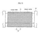
- a method for manufacturing a turbine stator vane according to a third embodiment will be explained with reference to a flow chart shown in Fig. 11 , Figs. 5(a) to (c) , Figs. 12(a) to 13 and Fig. 16(b) .
- the method for manufacturing a turbine stator vane according to the present embodiment is a method for manufacturing the turbine stator vane 23 shown in Fig. 3 .
- the present method includes an inner ply vane woven-fiber forming process, an inner ply vane infiltration process, an integrating process, an outer ply vane woven-fiber forming process, an outer ply vane infiltration process, a jig removal process, and a machining process. Then, specific workings in the processes in the manufacturing method according to the present embodiment are presented as follows.
- an inner ply vane woven-fiber formed body 17F constituted of ceramic fiber is formed on a surface of a jig 31.
- the inner ply vane woven-fiber formed body 17F is turned into the inner ply vane 17.
- the jig 31 is removed away from the inner ply vane woven-fiber formed body 17F or the inner ply vane 17.
- the rear filled member 25 that has a surface profile corresponding to the rear space S and the inner ply vane 17 are set to their prescribed positions on an integrating jig 39.
- the inner ply vane 17 and the rear filled member 25 are adjacently integrated.
- an integrated body 41 composed of the inner ply vane 17 and the rear filled member 25 is formed.
- an outer ply vane woven-fiber formed body 15F constituted of ceramic fiber is formed on the surface of the integrated body 41.
- ceramic matrix is infiltrated into the outer ply vane woven-fiber formed body 15F by a Chemical Vapor Infiltration method (CVI method), a Polymer Impregnation and Pyrolysis method (PIP method), a Solid Phase Infiltration method and so on.
- CVI method Chemical Vapor Infiltration method
- PIP method Polymer Impregnation and Pyrolysis method
- Solid Phase Infiltration method a Solid Phase Infiltration method and so on.
- the outer ply vane woven-fiber formed body 15F is turned into the outer ply vane 15. Note that arbitrary changes can be applied to an infiltration method of the ceramic matrix.
- the integrating jig 39 is removed away during or after this process, the rear filled member 25 remains in the rear space S.
- the outlet holes 27 and the eduction holes 29 are formed by a machining process.
- superfluous portions of the rear filled member 25 that protrudes from the outer ply vane 15 are also removed in this process.
- a coating process may be treated on surfaces of the outer ply vane 15 and the inner ply vane 17 by an arbitrary infiltration method after forming the outlet holes 27 and the eduction holes 29.
- the turbine stator vane 23 made of CMC is manufactured in this manner.
- the integrated body 41 is formed by the rear filled member 25 that has the surface profile corresponding to the rear space S and the inner ply vane 17, and the outer ply vane woven-fiber formed body 15F is formed on the surface of the integrated body 41. Therefore, the portion of the turbine stator vane 23 from the leading edge 23a to the intermediate position 23m (i.e. just anterior to the inner surface 15t of the inner ply vane 15 on the trailing-edge side) constructs a double ply structure with the outer ply vane 15 and the inner ply vane 17. The portion from the intermediate position 23m to the trailing edge 23t constructs a single ply structure only with the outer ply vane 15. As a result, the portion from the leading edge 23a to the intermediate position 23m in the turbine stator vane 23 made of CMC can be made thick and the portion from the intermediate position 23m to the trailing edge 23t can be made thin.
- the third embodiment can bring the same advantages as the above-explained turbine stator vane 23.
- a method for manufacturing a turbine stator vane according to a fourth embodiment will be explained with reference to a flow chart shown in Fig. 14 , Fig. 5 (a) and Figs. 15(a) to 16(b) .
- the method for manufacturing a turbine stator vane according to the fourth embodiment is a method for manufacturing the turbine stator vane 23 shown in Fig. 3 .
- the present method includes an inner ply vane woven-fiber forming process, an integrating process, an outer ply vane woven-fiber forming process, an infiltration process, a jig removal process, and a machining process. Then, specific workings in the processes in the manufacturing method according to the present embodiment are presented as follows.
- an inner ply vane woven-fiber formed body 17F constituted of ceramic fiber is formed on a surface of a jig 31.
- the rear filled member 25 that has a surface profile corresponding to the rear space S and the inner ply vane woven-fiber formed body 17F are adjacently integrated.
- an integrated body 41F composed of the inner ply vane woven-fiber formed body 17F and the rear filled member 25 is formed.
- an outer ply vane woven-fiber formed body 15F constituted of ceramic fiber is formed on the surface of the integrated body 41F.
- the jig 31 is removed away from the inner ply vane woven-fiber formed body 17F. Although the jig 31 is removed away, the rear filled member 25 remains in the rear space S.
- the outlet holes 27 and the eduction holes 29 are formed by carrying out a process similar to the machining process (step S37) in the third embodiment.
- superfluous portions of the rear filled member 25 that protrudes from the outer ply vane 15 are also removed in this process.
- a coating process may be treated on surfaces of the outer ply vane 15 and the inner ply vane 17 by an arbitrary infiltration method after forming the outlet holes 27 and the eduction holes 29.
- the turbine stator vane 23 made of CMC is manufactured in this manner.
- the integrated body 41F is formed by integrating the rear filled member 25 that has the surface profile corresponding to the rear space S and the inner ply vane woven-fiber formed body 17F, and the outer ply vane woven-fiber formed body 15F is formed on the surface of the integrated body 41F. Therefore, the portion of the turbine stator vane 23 from the leading edge 23a to the intermediate position 23m (i.e. just anterior to the inner surface 15t of the inner ply vane 15 on the trailing-edge side) constructs a double ply structure with the outer ply vane 15 and the inner ply vane 17. The portion from the intermediate position 23m to the trailing edge 23t constructs a single ply structure only with the outer ply vane 15. As a result, the portion from the leading edge 23a to the intermediate position 23m in the turbine stator vane 23 made of CMC can be made thick and the portion from the intermediate position 23m to the trailing edge 23t can be made thin.
- the fourth embodiment can bring the same advantages as the above-explained turbine stator vane 23.
- the present invention is not limited to the above descriptions in the embodiments.
- the configuration of the turbine stator vane 3, 23 can be applied to a turbine rotor blade, a compressor stator vane, a compressor rotor blade or the like.
- the method according to the first to fourth embodiments can be applied to a method for manufacturing a turbine rotor blade, a compressor stator vane, a compressor rotor blade or the like.
- the present invention can be carried out in other various ways.
- a scope of right included in the present invention is not limited to the above embodiments.
Abstract
Description
- The present invention relates to a method for manufacturing a vane to be used in a turbine or a compressor of a gas turbine engine such as a jet engine.
- A turbine vane (including a turbine stator vane and a turbine rotor blade) used in a turbine of a jet engine is generally constituted of heat-resistant alloy such as nickel alloy. Meanwhile, composite material such as ceramic matrix composite (CMC) that has superior heat-resistance property to nickel alloy and lower density than nickel alloy recently draws attention. A turbine blade constituted of ceramic matrix composite (CMC turbine vane) has also been developed (see
Patent Documents 1 and 2 listed below). And a CMC turbine vane is manufactured according to a following method. - Using a jig that has a surface profile corresponding to an inner surface profile of a turbine vane, ceramic fiber (fiber bundle of ceramic fiber) is woven two-dimensionally and/or three-dimensionally along a surface of the jig. By this process, a woven-fiber formed body constituted of ceramic fiber is formed on a surface of the jig. Subsequently, using an infiltration method such as Chemical Vapor Infiltration (CVI) or Polymer Impregnation and Pyrolysis (PIP), ceramic matrix is infiltrated into the woven-fiber formed body. Then, the infiltrated woven-fiber formed body is treated with a machining process and so on, and thereby a CMC turbine vane is manufactured.
-
- Patent Document 1: Japanese Patent Application laid-Open No.
2001-206779 - Patent Document 2: Japanese Patent Application laid-Open No.
2003-148105 - Generally, a CMC turbine vane is needed to be thicker as a whole than a turbine vane made of heat-resistant alloy in order to secure rigidity of the CMC turbine vane. Accompanying with this, a trailing edge of the turbine vane is subject to be thick. Meanwhile, if a trailing edge of a turbine vane is thick, mixture loss of swirls generated near the trailing edge of the turbine vane and a main flow increases. As a result, pressure loss increases and thereby it becomes difficult to improve turbine efficiency.
- Note that this issue occurs not only in a turbine vane made of composite material used in a turbine of a gas turbine engine but also in a compressor vane (including a compressor stator vane and a compressor rotor blade) made of composite material used in a gas turbine compressor.
- An object of the present invention is to provide a method for manufacturing a vane that can improve turbine efficiency by reducing thickness of a trailing edge of the vane.
- Any of following aspects of the present invention relates to manufacturing of a vane that is to be used in a turbine or a compressor of a gas turbine engine and made of composite material constituted of reinforcement fiber and matrix, and comprises; an outer ply vane that is made of composite material constituted of reinforcement fiber and matrix; and an inner ply vane that is made of composite material constituted of reinforcement fiber and matrix, and extends from an inner surface of the outer ply vane on a leading-edge side toward an inner surface of the outer ply vane on a trailing-edge side, a convex-side outer surface thereof being stuck integrally with a convex-side inner surface of the outer ply vane, and a concave-side outer surface thereof being stuck integrally with a concave-side inner surface of the outer ply vane; wherein a rear space is segmented within the outer ply vane between an outer surface of the inner ply vane on the trailing-edge side and an inner surface of the outer ply vane on the trailing-edge side.
A first aspect of the present invention provides a method for manufacturing the above vane that comprises: (a) forming an inner ply vane woven-fiber formed body constituted of reinforcement fiber on a surface of a jig that has a surface profile corresponding to an inner surface profile of the inner ply vane; (b) infiltrating matrix into the inner ply vane woven-fiber formed body to turn the inner ply vane woven-fiber formed body into the inner ply vane; (c), during or after (b), removing the jig away from the inner ply vane woven-fiber formed body or the inner ply vane; (d), after (b) and (c), integrating a supplemental jig that has a surface profile corresponding to the rear space and the inner ply vane to form a integrated body; (e), after (d), forming an outer ply vane woven-fiber formed body constituted of reinforcement fiber on a surface of the integrated body; (f), after (e), infiltrating matrix into the outer ply vane woven-fiber formed body to turn the outer ply vane woven-fiber formed body into the outer ply vane; and (g), during or after (f), removing the supplemental jig away from the outer ply vane woven-fiber formed body or the outer ply vane. - A second aspect of the present invention provides a method for manufacturing the above vane that comprises: (A) forming an inner ply vane woven-fiber formed body constituted of reinforcement fiber on a surface of a jig that has a surface profile corresponding to an inner surface profile of the inner ply vane; (B), after (A), integrating a supplemental jig that has a surface profile corresponding to the rear space and the inner ply vane woven-fiber formed body to form a integrated body; (C), after (B), forming an outer ply vane woven-fiber formed body constituted of reinforcement fiber on a surface of the integrated body; (D), after (C), infiltrating matrix into the inner ply vane woven-fiber formed body and the outer ply vane woven-fiber formed body to turn the inner ply vane woven-fiber formed body and the outer ply vane woven-fiber formed body into the inner ply vane and the outer ply vane, respectively; and (E), during or after (D), removing the jig away from the inner ply vane woven-fiber formed body or the inner ply vane, and removing the supplemental jig away from the outer ply vane woven-fiber formed body or the outer ply vane.
- A third aspect of the present invention provides a method for manufacturing the above vane that comprises: (i) forming an inner ply vane woven-fiber formed body constituted of reinforcement fiber on a surface of a jig that has a surface profile corresponding to an inner surface profile of the inner ply vane; (ii) infiltrating matrix into the inner ply vane woven-fiber formed body to turn the inner ply vane woven-fiber formed body into the inner ply vane; (iii), during or after (ii), removing the jig away from the inner ply vane woven-fiber formed body or the inner ply vane; (iv), after (ii) and (iii), integrating a rear filled member that has a surface profile corresponding to the rear space and the inner ply vane to form a integrated body; (v), after (iv), forming an outer ply vane woven-fiber formed body constituted of reinforcement fiber on a surface of the integrated body; and (vi), after (v), infiltrating matrix into the outer ply vane woven-fiber formed body to turn the outer ply vane woven-fiber formed body into the outer ply vane.
- A fourth aspect of the present invention provides a method for manufacturing the above vane that comprises: (I) forming an inner ply vane woven-fiber formed body constituted of reinforcement fiber on a surface of a jig that has a surface profile corresponding to an inner surface profile of the inner ply vane; (II), after (I), integrating a rear filled member that has a surface profile corresponding to the rear space and the inner ply vane woven-fiber formed body to form a integrated body; (III), after (II), forming an outer ply vane woven-fiber formed body constituted of reinforcement fiber on a surface of the integrated body; (IV), after (III), infiltrating matrix into the inner ply vane woven-fiber formed body and the outer ply vane woven-fiber formed body to turn the inner ply vane woven-fiber formed body and the outer ply vane woven-fiber formed body into the inner ply vane and the outer ply vane, respectively; and (V), during or after (IV), removing the jig away from the inner ply vane woven-fiber formed body or the inner ply vane.
- According to the above aspects, since a portion from a leading edge to an intermediate position in the vane made of composite material can be made thick and a portion from the intermediate position to a trailing edge can be made thin, rigidity of the vane made of composite material can be secured and also the trailing edge of the vane can be made thin. As a result, since pressure loss near the trailing edge of the vane can be restricted, turbine efficiency or compressor efficiency can be improved.
- Here, it is preferable that the composite material is ceramic matrix composite or carbon-based composite material. Since ceramic matrix composite or carbon-based composite material has higher heatproof temperature than metal, cooling of the vane under high temperature environment can be eliminated or cooling air volume can be reduced and the efficiency can be improved. In addition, since ceramic matrix composite or carbon-based composite material has lower density than metal and can reduce component weight, weight reduction can be achieved and fuel consumption rate can be improved.
- Note that, in the present application, a term "vane" includes a "turbine vane" and a "compressor vane". In addition, a term "turbine vane" includes a "turbine stator vane" and a "turbine rotor blade". Further, a term "compressor vane" includes a "compressor stator vane" and a "compressor rotor blade".
-
- [
Fig. 1 ] is a cross-sectional view of a turbine stator vane (a cross-sectional view take along a line I-I shown inFig. 2 ). - [
Fig. 2 ] is a side view of a turbine stator segment (partially cross-sectioned). - [
Fig. 3 ] is a cross-sectional view of a turbine stator vane (another configuration). - [
Fig. 4] Fig. 4 is a flowchart of a method for manufacturing the turbine stator vane according to a first embodiment. - [
Fig. 5] Fig. 5(a) is an explanatory drawing of an inner ply vane woven-fiber forming process in the first [second, third, forth] embodiment,Fig. 5(b) is an explanatory drawing of an inner ply vane infiltration process in the first [third] embodiment, andFig. 5(c) is an explanatory drawing of a jig removal process in the first [third] embodiment. - [
Fig. 6] Fig. 6(a) is an explanatory drawing of an integrating process in the first embodiment, andFig. 6(b) is an explanatory drawing of an outer ply vane woven-fiber forming process. - [
Fig. 7] Fig. 7 (a) is an explanatory drawing of an outer ply vane infiltration process in the first embodiment, andFig. 7(b) is an explanatory drawing of a supplemental jig removal process. - [
Fig. 8] Fig. 8 is a flowchart of a method for manufacturing the turbine stator vane according to a second embodiment. - [
Fig. 9] Fig. 9 (a) is an explanatory drawing of an integrating process in the second embodiment, andFig. 9(b) is an explanatory drawing of an outer ply vane woven-fiber forming process. - [
Fig. 10] Fig. 10 (a) is an explanatory drawing of an outer ply vane infiltration process in the second embodiment, andFig. 10(b) is an explanatory drawing of a removal process. - [
Fig. 11] Fig. 11 is a flowchart of a method for manufacturing the turbine stator vane according to a third embodiment. - [
Fig. 12] Fig. 12(a) is an explanatory drawing of an integrating process in the third embodiment, andFig. 12 (b) is an explanatory drawing of an outer ply vane woven-fiber forming process. - [
Fig. 13] Fig. 13 is an explanatory drawing of an outer ply vane infiltration process in the third embodiment. - [
Fig. 14] Fig. 14 is a flowchart of a method for manufacturing the turbine stator vane according to a fourth embodiment. - [
Fig. 15] Fig. 15(a) is an explanatory drawing of an integrating process in the fourth embodiment, andFig. 15(b) is an explanatory drawing of an outer ply vane woven-fiber forming process. - [
Fig. 16] Fig. 16(a) is an explanatory drawing of an infiltration process in the fourth embodiment, andFig. 16(b) is an explanatory drawing of a removal process. - First, a
turbine stator vane 3 manufactured by after-described embodiments of a manufacturing method will be explained with reference toFigs. 1 and2 . Note that, in the drawings, an "F" indicates a forward direction (an upstream direction), an "R" in the drawings indicates a rearward direction (a downstream direction), an "In" indicates a radially-inward direction, and an "Out" indicates a radially-outward direction. - A turbine stator (turbine nozzle) used in a turbine (not shown) of a jet engine is segmented into plural turbine stator segments (turbine nozzle segments) 1 along its circumferential direction (see
Fig. 2 ). - The
turbine stator segment 1 includes plural turbine stator vanes 3 (only one of them is shown). Theturbine stator vane 3 is constituted of Ceramic Matrix Composites (a type of composite materials, hereinafter referred to as CMC) that is made of ceramic matrix (a type of matrixes) and ceramic fiber (a type of reinforcement fibers). Note that a detail constitution of theturbine stator vane 3 will be described later. - An arch-shaped outer band 5 is provided integrally on an outer end (radially outer end) of the
turbine stator vane 3. The outer band 5 is constituted of heat-resistant alloy such as nickel alloy. In addition, an arch-shaped front flange 7 that is to be engaged with a portion of a turbine case (not shown) is formed on a front side of the outer band 5. Similarly, an arch-shaped rear flange 9 that is to be engaged with a portion of the turbine case is formed on a rear side of the outer band 5. Note that the outer band 5 may be constituted of composite materials such as CMC and carbon-based composite materials instead of heat-resistant alloy. - An arch-shaped
inner band 11 is provided integrally on an inner end (radially inner end) of theturbine stator vane 3. Theinner band 11 is constituted of heat-resistant alloy such as nickel alloy. In addition, an arch-shapedrib 13 that is to be fit with a groove (not shown) on a stator support member integrally coupled with the turbine case. Note that theinner band 11 may be constituted of composite materials such as CMC and carbon-based composite materials instead of heat-resistant alloy. - Next, a detail constitution of the
turbine stator vane 3 will be explained. - As shown in
Fig. 1 , theturbine stator vane 3 includes a hollow outer ply vane (an outer vane) 15. Theouter ply vane 15 is constituted of CMC that is made of ceramic fiber and ceramic matrix. Note that carbon fiber, glass fiber or blending fiber of these (blending fiber made of two or more kinds of ceramic fiber, carbon fiber and glass fiber) may be used instead of ceramic fiber. Note that carbon matrix or glass matrix may be used instead of ceramic matrix. - An inner ply vane (inner vane) 17 is provided integrally on an inner surface of the
outer ply vane 15. Theinner ply vane 17 is constituted of CMC that is made of ceramic fiber and ceramic matrix. In addition, theinner ply vane 17 extends from aninner surface 15a of theouter ply vane 15 on a leading-edge side toward aninner surface 15t of theouter ply vane 15 on a trailing-edge side. Anouter surface 17t of theinner ply vane 17 on the trailing-edge side is positioned nearer to the trailing-edge side than a middle position (middle position along a chord length) of theinner ply vane 17. Further, anouter surface 17d of theinner ply vane 17 on a convex-side is stuck integrally with a convex-sideinner surface 15d of theouter ply vane 15. Similarly, anouter surface 17v of theinner ply vane 17 on a concave-side is stuck integrally with a concave-sideinner surface 15v of theouter ply vane 15. Note that carbon fiber, glass fiber or blending fiber of these may be used instead of ceramic fiber. In addition, carbon matrix or glass matrix may be used instead of ceramic matrix. - Then, a rear space S is segmented within the
outer ply vane 15 between theouter surface 17t of theinner ply vane 17 on the trailing-edge side and theinner surface 15t of theouter ply vane 15 on the trailing-edge side. - Plural outlet holes 19 are formed on a
leading edge 3a and a concave surface 3v of theturbine stator vane 3 to inject cooling air introduced into an inside of theinner ply vane 17 through a front insert (not shown). Each of the outlet holes 19 penetrates theouter ply vane 15 and theinner ply vane 17. In addition, plural eduction holes 21 are formed on a trailingedge 3t of theturbine stator vane 3 to discharge cooling air introduced into an inside of the rear space S through a rear insert (not shown) . Each of the eduction holes 21 penetrates theouter ply vane 15. Note that the cooling air is compressed air extracted from a compressor (not shown) of the jet engine. - Next, advantages of the
turbine stator vane 3 will be explained. - As described above, the hollow
inner ply vane 17 is integrally provided on the inner surface of the hollowouter ply vane 15, and the rear space S is segmented between theouter surface 17t of theinner ply vane 17 on the trailing-edge side and theinner surface 15t of theinner ply vane 15 on the trailing-edge side. Therefore, a portion of theturbine stator vane 3 from theleading edge 3a to anintermediate position 3m (i.e. just anterior to theinner surface 15t of theinner ply vane 15 on the trailing-edge side) constructs a double ply structure with theouter ply vane 15 and theinner ply vane 17. A portion from theintermediate position 3m to the trailingedge 3t constructs a single ply structure only with theouter ply vane 15. As a result, the portion from theleading edge 3a to theintermediate position 3m in theturbine stator vane 3 made of CMC can be made thick and the portion from theintermediate position 3m to the trailingedge 3t can be made thin. - Therefore, according to the
turbine stator vane 3, rigidity of theturbine stator vane 3 made of CMC is secured and also the trailingedge 3t is made thin, so that it becomes possible to restrict a rise of pressure loss near the trailingedge 3t and thereby to improve turbine efficiency. - Next, another configuration of a turbine stator vane manufactured by after-described embodiments of a manufacturing method will be explained with reference to
Fig. 3 . - As shown in
Fig. 3 , aturbine stator vane 23 is used in a turbine of a jet engine, and schematically has the same configurations as those of the above-explainedturbine stator vane 3. Only different points from the specific configurations of theturbine stator vane 3 will be explained among the specific configurations of theturbine stator vane 23. Note that the configurations of theturbine stator vane 23 identical or similar to the configurations of theturbine stator vane 3 will be indicated by identical reference numerals in the drawings and their explanations will be avoided. - In the
turbine stator vane 23, the rear space S is filled with a rear filled member (rear core member) 25. The rear filledmember 25 is provided integrally with theouter ply vane 15 and theinner ply vane 17. - Plural outlet holes 27 are formed on a
leading edge 23a and aconcave surface 23v of theturbine stator vane 23 to inject cooling air introduced into the inside of theinner ply vane 17 through the front insert (not shown). Each of the outlet holes 27 penetrates theouter ply vane 15 and theinner ply vane 17. In addition, plural eduction holes 29 are formed on a trailingedge 23t of theturbine stator vane 23 to discharge the cooling air introduced into the inside of the rear space S through the rear insert (not shown). Each of the eduction holes 29 penetrates theouter ply vane 15, the rear filledmember 25 and theinner ply vane 17. - Note that the
turbine stator vane 23 can also bring the same advantages as the above-explainedturbine stator vane 3. However, in theturbine stator vane 23, the rear space S of the above-explainedturbine stator vane 3 is filled with the rear filledmember 25. Strength and rigidity of vane trailing edge portion of theturbine stator vane 23 can be improved by filling of the rear filledmember 25. - A method for manufacturing a turbine stator vane according to a first embodiment will be explained with reference to a flow chart shown in
Fig. 4 andFigs. 5(a) to 7(b) . - The method for manufacturing a turbine stator vane according to the present embodiment is a method for manufacturing the
turbine stator vane 3 shown inFig. 1 . The present method includes an inner ply vane woven-fiber forming process, an inner ply vane infiltration process, a jig removal process, an integrating process, an outer ply vane woven-fiber forming process, an outer ply vane infiltration process, a supplemental jig removal process, and a machining process. Then, specific workings in the processes in the manufacturing method according to the present embodiment are presented as follows. - As shown in
Fig. 5(a) , using ajig 31 that has a surface profile corresponding to an inner surface profile of theinner ply vane 17, ceramic fiber (fiber bundle of ceramic fiber) is woven two-dimensionally and/or three-dimensionally along a surface of thejig 31 in braid weave, plain weave or the like. By this process, an inner ply vane woven-fiber formedbody 17F constituted of ceramic fiber is formed on the surface of thejig 31. Note that arbitrary changes can be applied to a weave style of the ceramic fiber. - As shown in
Fig. 5 (b) , after the inner ply vane woven-fiber forming process, ceramic matrix is infiltrated into the inner ply vane woven-fiber formedbody 17F by a Chemical Vapor Infiltration method (CVI method), a Polymer Impregnation and Pyrolysis method (PIP method), a Solid Phase Infiltration method and so on. By this process, the inner ply vane woven-fiber formedbody 17F is turned into theinner ply vane 17. Note that arbitrary changes can be applied to an infiltration method of the ceramic matrix. - As shown in
Fig. 5 (c) , during or after the inner ply vane infiltration process, thejig 31 is moved laterally, so that thejig 31 is removed away from the inner ply vane woven-fiber formedbody 17F or theinner ply vane 17. - As shown in
Fig. 6(a) , after the inner ply vane infiltration process and the jig removal process, asupplemental jig 33 that has a surface profile corresponding to the rear space S and theinner ply vane 17 are set to their prescribed positions on an integratingjig 37. Here, theinner ply vane 17 and thesupplemental jig 33 are adjacently integrated. By this process, anintegrated body 35 composed of theinner ply vane 17 and thesupplemental jig 33 is formed. - As shown in
Fig. 6(b) , after the integrating process, ceramic fiber (fiber bundle of ceramic fiber) is woven two-dimensionally and/or three-dimensionally along a surface of theintegrated body 35 in braid weave, plain weave or the like. By this process, an outer ply vane woven-fiber formedbody 15F constituted of ceramic fiber is formed on the surface of theintegrated body 35. Note that arbitrary changes can be applied to a weave style of the ceramic fiber. In addition, the outer ply vane woven-fiber formedbody 15F may be formed by winding woven-fiber made of ceramic fiber on the surface of theintegrated body 35 instead of by weaving the ceramic fiber. - As shown in
Fig. 7 (a) , after the outer ply vane woven-fiber forming process, ceramic matrix is infiltrated into the outer ply vane woven-fiber formedbody 15F by a Chemical Vapor Infiltration method (CVI method), a Polymer Impregnation and Pyrolysis method (PIP method), a Solid Phase Infiltration method and so on. By this process, the outer ply vane woven-fiber formedbody 15F is turned into theouter ply vane 15. Note that arbitrary changes can be applied to an infiltration method of the ceramic matrix. - As shown in
Fig. 7 (b) , during or after the outer ply vane infiltration process, thesupplemental jig 33 is moved laterally, so that thesupplemental jig 33 is removed away from the outer ply vane woven-fiber formedbody 15F or theouter ply vane 15. - After the removal process, the outlet holes 19 and the eduction holes 21 are formed by a machining process. Note that it is preferable that a coating process may be treated on surfaces of the
outer ply vane 15 and theinner ply vane 17 by an arbitrary infiltration method after forming the outlet holes 19 and the eduction holes 21. - The
turbine stator vane 3 made of CMC is manufactured in this manner. - Subsequently, advantages of the first embodiment will be explained.
- As described above, the
integrated body 35 is formed by thesupplemental jig 33 that has the surface profile corresponding to the rear space S and theinner ply vane 17, and the outer ply vane woven-fiber formedbody 15F is formed on the surface of theintegrated body 35. Therefore, the portion of theturbine stator vane 3 from theleading edge 3a to theintermediate position 3m (i.e. just anterior to theinner surface 15t of theinner ply vane 15 on the trailing-edge side) constructs a double ply structure with theouter ply vane 15 and theinner ply vane 17. The portion from theintermediate position 3m to the trailingedge 3t constructs a single ply structure only with theouter ply vane 15. As a result, the portion from theleading edge 3a to theintermediate position 3m in theturbine stator vane 3 made of CMC can be made thick and the portion from theintermediate position 3m to the trailingedge 3t can be made thin. - Therefore, the first embodiment can bring the same advantages as the above-explained
turbine stator vane 3. - A method for manufacturing a turbine stator vane according to a second embodiment will be explained with reference to a flow chart shown in
Fig. 8 ,Fig. 5(a) andFigs. 9(a) to 10(b) . - The method for manufacturing a turbine stator vane according to the present embodiment is a method for manufacturing the
turbine stator vane 3 shown inFig. 1 . The present method includes an inner ply vane woven-fiber forming process, an integrating process, an outer ply vane woven-fiber forming process, an infiltration process, a removal process, and a machining process. Then, specific workings in the processes in the manufacturing method according to the present embodiment are presented as follows. - As shown in
Fig. 5(a) , by carrying out a process similar to the inner ply vane woven-fiber forming process (step S11) in the first embodiment, an inner ply vane woven-fiber formedbody 17F constituted of ceramic fiber is formed on a surface of ajig 31. - As shown in
Fig. 9(a) , after the inner ply vane infiltration process, asupplemental jig 33 that has a surface profile corresponding to the rear space S and the inner ply vane woven-fiber formedbody 17F are adjacently integrated. By this process, anintegrated body 35F composed of the inner ply vane woven-fiber formedbody 17F and thesupplemental jig 33 is formed. - As shown in
Fig. 9(b) , after the integrating process, by carrying out a process similar to the outer ply vane woven-fiber forming process (step S15) in the first embodiment, an outer ply vane woven-fiber formedbody 15F constituted of ceramic fiber is formed on the surface of theintegrated body 35F. - As shown in
Fig. 10(a) , after the outer ply vane woven-fiber forming process, ceramic matrix is infiltrated into the outer ply vane woven-fiber formedbody 15F and the inner ply vane woven-fiber formedbody 17F by a Chemical Vapor Infiltration method (CVI method), a Polymer Impregnation and Pyrolysis method (PIP method), a Solid Phase Infiltration method and so on. By this process, the outer ply vane woven-fiber formedbody 15F and the inner ply vane woven-fiber formedbody 17F are turned into theouter ply vane 15 and theinner ply vane 17, respectively. - As shown in
Fig. 10(b) , during or after the infiltration process, thejig 31 and thesupplemental jig 33 are moved laterally, so that thejig 31 is removed away from the inner ply vane woven-fiber formedbody 17F or theinner ply vane 17 and thesupplemental jig 33 is removed away from the outer ply vane woven-fiber formedbody 15F or theouter ply vane 15. - After the removal process, the outlet holes 19 and the eduction holes 21 are formed by carrying out a process similar to the machining process (step S18) in the first embodiment. Note that it is preferable that a coating process may be treated on surfaces of the
outer ply vane 15 and theinner ply vane 17 by an arbitrary infiltration method after forming the outlet holes 27 and the eduction holes 29. - The
turbine stator vane 3 made of CMC is manufactured in this manner. - Subsequently, advantages of the second embodiment will be explained.
- As described above, the
integrated body 35F is formed by thesupplemental jig 33 that has the surface profile corresponding to the rear space S and the inner ply vane woven-fiber formedbody 17F, and the outer ply vane woven-fiber formedbody 15F is formed on the surface of theintegrated body 35F. Therefore, the portion of theturbine stator vane 3 from theleading edge 3a to theintermediate position 3m (i.e. just anterior to theinner surface 15t of theinner ply vane 15 on the trailing-edge side) constructs a double ply structure with theouter ply vane 15 and theinner ply vane 17. The portion from theintermediate position 3m to the trailingedge 3t constructs a single ply structure only with theouter ply vane 15. As a result, the portion from theleading edge 3a to theintermediate position 3m in theturbine stator vane 3 made of CMC can be made thick and the portion from theintermediate position 3m to the trailingedge 3t can be made thin. - Therefore, the second embodiment can bring the same advantages as the above-explained
turbine stator vane 3. - A method for manufacturing a turbine stator vane according to a third embodiment will be explained with reference to a flow chart shown in
Fig. 11 ,Figs. 5(a) to (c) ,Figs. 12(a) to 13 andFig. 16(b) . - The method for manufacturing a turbine stator vane according to the present embodiment is a method for manufacturing the
turbine stator vane 23 shown inFig. 3 . The present method includes an inner ply vane woven-fiber forming process, an inner ply vane infiltration process, an integrating process, an outer ply vane woven-fiber forming process, an outer ply vane infiltration process, a jig removal process, and a machining process. Then, specific workings in the processes in the manufacturing method according to the present embodiment are presented as follows. - As shown in
Fig. 5(a) , by carrying out a process similar to the inner ply vane woven-fiber forming process (step S11) in the first embodiment, an inner ply vane woven-fiber formedbody 17F constituted of ceramic fiber is formed on a surface of ajig 31. - As shown in
Fig. 5 (b) , after the inner ply vane woven-fiber forming process, by carrying out a process similar to the inner ply vane infiltration process (step S12) in the first embodiment, the inner ply vane woven-fiber formedbody 17F is turned into theinner ply vane 17. - As shown in
Fig. 5 (c) , during or after the inner ply vane infiltration process, by carrying out a process similar to the jig removal process (step S13) in the first embodiment, thejig 31 is removed away from the inner ply vane woven-fiber formedbody 17F or theinner ply vane 17. - As shown in
Fig. 12(a) , after the inner ply vane infiltration process and the jig removal process, the rear filledmember 25 that has a surface profile corresponding to the rear space S and theinner ply vane 17 are set to their prescribed positions on an integratingjig 39. Here, theinner ply vane 17 and the rear filledmember 25 are adjacently integrated. By this process, anintegrated body 41 composed of theinner ply vane 17 and the rear filledmember 25 is formed. - As shown in
Fig. 12(b) , after the integrating process, by carrying out a process similar to the outer ply vane woven-fiber forming process (step S15) in the first embodiment, an outer ply vane woven-fiber formedbody 15F constituted of ceramic fiber is formed on the surface of theintegrated body 41. - As shown in
Fig. 13 , after the outer ply vane woven-fiber forming process, ceramic matrix is infiltrated into the outer ply vane woven-fiber formedbody 15F by a Chemical Vapor Infiltration method (CVI method), a Polymer Impregnation and Pyrolysis method (PIP method), a Solid Phase Infiltration method and so on. By this process, the outer ply vane woven-fiber formedbody 15F is turned into theouter ply vane 15. Note that arbitrary changes can be applied to an infiltration method of the ceramic matrix. Although the integratingjig 39 is removed away during or after this process, the rear filledmember 25 remains in the rear space S. - After the outer ply vane infiltration process, the outlet holes 27 and the eduction holes 29 are formed by a machining process. In addition, superfluous portions of the rear filled
member 25 that protrudes from theouter ply vane 15 are also removed in this process. Note that it is preferable that a coating process may be treated on surfaces of theouter ply vane 15 and theinner ply vane 17 by an arbitrary infiltration method after forming the outlet holes 27 and the eduction holes 29. - The
turbine stator vane 23 made of CMC is manufactured in this manner. - Subsequently, advantages of the third embodiment will be explained.
- As described above, the
integrated body 41 is formed by the rear filledmember 25 that has the surface profile corresponding to the rear space S and theinner ply vane 17, and the outer ply vane woven-fiber formedbody 15F is formed on the surface of theintegrated body 41. Therefore, the portion of theturbine stator vane 23 from theleading edge 23a to theintermediate position 23m (i.e. just anterior to theinner surface 15t of theinner ply vane 15 on the trailing-edge side) constructs a double ply structure with theouter ply vane 15 and theinner ply vane 17. The portion from theintermediate position 23m to the trailingedge 23t constructs a single ply structure only with theouter ply vane 15. As a result, the portion from theleading edge 23a to theintermediate position 23m in theturbine stator vane 23 made of CMC can be made thick and the portion from theintermediate position 23m to the trailingedge 23t can be made thin. - Therefore, the third embodiment can bring the same advantages as the above-explained
turbine stator vane 23. - A method for manufacturing a turbine stator vane according to a fourth embodiment will be explained with reference to a flow chart shown in
Fig. 14 ,Fig. 5 (a) andFigs. 15(a) to 16(b) . - The method for manufacturing a turbine stator vane according to the fourth embodiment is a method for manufacturing the
turbine stator vane 23 shown inFig. 3 . The present method includes an inner ply vane woven-fiber forming process, an integrating process, an outer ply vane woven-fiber forming process, an infiltration process, a jig removal process, and a machining process. Then, specific workings in the processes in the manufacturing method according to the present embodiment are presented as follows. - As shown in
Fig. 5(a) , by carrying out a process similar to the inner ply vane woven-fiber forming process (step S11) in the first embodiment, an inner ply vane woven-fiber formedbody 17F constituted of ceramic fiber is formed on a surface of ajig 31. - As shown in
Fig. 15(a) , after the inner ply vane infiltration process, the rear filledmember 25 that has a surface profile corresponding to the rear space S and the inner ply vane woven-fiber formedbody 17F are adjacently integrated. By this process, anintegrated body 41F composed of the inner ply vane woven-fiber formedbody 17F and the rear filledmember 25 is formed. - As shown in
Fig. 15(b) , after the integrating process, by carrying out a process similar to the outer ply vane woven-fiber forming process (step S15) in the first embodiment, an outer ply vane woven-fiber formedbody 15F constituted of ceramic fiber is formed on the surface of theintegrated body 41F. - As shown in
Fig. 16(a) , after the outer ply vane woven-fiber forming process, ceramic matrix is infiltrated into the outer ply vane woven-fiber formedbody 15F and the inner ply vane woven-fiber formedbody 17F by a Chemical Vapor Infiltration method (CVI method), a Polymer Impregnation and Pyrolysis method (PIP method), a Solid Phase Infiltration method and so on. By this process, the outer ply vane woven-fiber formedbody 15F and the inner ply vane woven-fiber formedbody 17F are turned into theouter ply vane 15 and theinner ply vane 17, respectively. - As shown in
Fig. 16(b) , during or after the infiltration process, by carrying out a process similar to the jig removal process (step S33) in the third embodiment, thejig 31 is removed away from the inner ply vane woven-fiber formedbody 17F. Although thejig 31 is removed away, the rear filledmember 25 remains in the rear space S. - After the jig removal process, the outlet holes 27 and the eduction holes 29 are formed by carrying out a process similar to the machining process (step S37) in the third embodiment. In addition, superfluous portions of the rear filled
member 25 that protrudes from theouter ply vane 15 are also removed in this process. Note that it is preferable that a coating process may be treated on surfaces of theouter ply vane 15 and theinner ply vane 17 by an arbitrary infiltration method after forming the outlet holes 27 and the eduction holes 29. - The
turbine stator vane 23 made of CMC is manufactured in this manner. - Subsequently, advantages of the fourth embodiment will be explained.
- The
integrated body 41F is formed by integrating the rear filledmember 25 that has the surface profile corresponding to the rear space S and the inner ply vane woven-fiber formedbody 17F, and the outer ply vane woven-fiber formedbody 15F is formed on the surface of theintegrated body 41F. Therefore, the portion of theturbine stator vane 23 from theleading edge 23a to theintermediate position 23m (i.e. just anterior to theinner surface 15t of theinner ply vane 15 on the trailing-edge side) constructs a double ply structure with theouter ply vane 15 and theinner ply vane 17. The portion from theintermediate position 23m to the trailingedge 23t constructs a single ply structure only with theouter ply vane 15. As a result, the portion from theleading edge 23a to theintermediate position 23m in theturbine stator vane 23 made of CMC can be made thick and the portion from theintermediate position 23m to the trailingedge 23t can be made thin. - Therefore, the fourth embodiment can bring the same advantages as the above-explained
turbine stator vane 23. - Note that the present invention is not limited to the above descriptions in the embodiments. For example, the configuration of the
turbine stator vane
Claims (8)
- A method for manufacturing a vane that is to be used in a turbine or a compressor of a gas turbine engine and made of composite material constituted of reinforcement fiber and matrix,
the vane comprising:an outer ply vane that is made of composite material constituted of reinforcement fiber and matrix; andan inner ply vane that is made of composite material constituted of reinforcement fiber and matrix, and extends from an inner surface of the outer ply vane on a leading-edge side toward an inner surface of the outer ply vane on a trailing-edge side, a convex-side outer surface thereof being stuck integrally with a convex-side inner surface of the outer ply vane, and a concave-side outer surface thereof being stuck integrally with a concave-side inner surface of the outer ply vane;wherein a rear space is segmented within the outer ply vane between an outer surface of the inner ply vane on the trailing-edge side and an inner surface of the outer ply vane on the trailing-edge side, andthe method comprising:(a) forming an inner ply vane woven-fiber formed body constituted of reinforcement fiber on a surface of a jig that has a surface profile corresponding to an inner surface profile of the inner ply vane;(b) infiltrating matrix into the inner ply vane woven-fiber formed body to turn the inner ply vane woven-fiber formed body into the inner ply vane;(c) during or after (b), removing the jig away from the inner ply vane woven-fiber formed body or the inner ply vane;(d) after (b) and (c), integrating a supplemental jig that has a surface profile corresponding to the rear space and the inner ply vane to form a integrated body;(e) after (d), forming an outer ply vane woven-fiber formed body constituted of reinforcement fiber on a surface of the integrated body;(f) after (e), infiltrating matrix into the outer ply vane woven-fiber formed body to turn the outer ply vane woven-fiber formed body into the outer ply vane; and(g) during or after (f), removing the supplemental jig away from the outer ply vane woven-fiber formed body or the outer ply vane. - The method for manufacturing a vane according to claim 1, wherein
the composite material is ceramic matrix composite or carbon-based composite material. - A method for manufacturing a vane that is to be used in a turbine or a compressor of a gas turbine engine and made of composite material constituted of reinforcement fiber and matrix,
the vane comprising:an outer ply vane that is made of composite material constituted of reinforcement fiber and matrix; andan inner ply vane that is made of composite material constituted of reinforcement fiber and matrix, and extends from an inner surface of the outer ply vane on a leading-edge side toward an inner surface of the outer ply vane on a trailing-edge side, a convex-side outer surface thereof being stuck integrally with a convex-side inner surface of the outer ply vane, and a concave-side outer surface thereof being stuck integrally with a concave-side inner surface of the outer ply vane;wherein a rear space is segmented within the outer ply vane between an outer surface of the inner ply vane on the trailing-edge side and an inner surface of the outer ply vane on the trailing-edge side, andthe method comprising:(A) forming an inner ply vane woven-fiber formed body constituted of reinforcement fiber on a surface of a jig that has a surface profile corresponding to an inner surface profile of the inner ply vane;(B) after (A), integrating a supplemental jig that has a surface profile corresponding to the rear space and the inner ply vane woven-fiber formed body to form a integrated body;(C) after (B), forming an outer ply vane woven-fiber formed body constituted of reinforcement fiber on a surface of the integrated body;(D) after (C), infiltrating matrix into the inner ply vane woven-fiber formed body and the outer ply vane woven-fiber formed body to turn the inner ply vane woven-fiber formed body and the outer ply vane woven-fiber formed body into the inner ply vane and the outer ply vane, respectively; and(E) during or after (D), removing the jig away from the inner ply vane woven-fiber formed body or the inner ply vane, and removing the supplemental jig away from the outer ply vane woven-fiber formed body or the outer ply vane. - The method for manufacturing a vane according to claim 3, wherein
the composite material is ceramic matrix composite or carbon-based composite material. - A method for manufacturing a vane that is to be used in a turbine or a compressor of a gas turbine engine and made of composite material constituted of reinforcement fiber and matrix,
the vane comprising:an outer ply vane that is made of composite material constituted of reinforcement fiber and matrix; andan inner ply vane that is made of composite material constituted of reinforcement fiber and matrix, and extends from an inner surface of the outer ply vane on a leading-edge side toward an inner surface of the outer ply vane on a trailing-edge side, a convex-side outer surface thereof being stuck integrally with a convex-side inner surface of the outer ply vane, and a concave-side outer surface thereof being stuck integrally with a concave-side inner surface of the outer ply vane;wherein a rear space is segmented within the outer ply vane between an outer surface of the inner ply vane on the trailing-edge side and an inner surface of the outer ply vane on the trailing-edge side, andthe method comprising:(i) forming an inner ply vane woven-fiber formed body constituted of reinforcement fiber on a surface of a jig that has a surface profile corresponding to an inner surface profile of the inner ply vane;(ii) infiltrating matrix into the inner ply vane woven-fiber formed body to turn the inner ply vane woven-fiber formed body into the inner ply vane;(iii) during or after (ii), removing the jig away from the inner ply vane woven-fiber formed body or the inner ply vane;(iv) after (ii) and (iii), integrating a rear filled member that has a surface profile corresponding to the rear space and the inner ply vane to form a integrated body;(v) after (iv), forming an outer ply vane woven-fiber formed body constituted of reinforcement fiber on a surface of the integrated body; and(vi) after (v), infiltrating matrix into the outer ply vane woven-fiber formed body to turn the outer ply vane woven-fiber formed body into the outer ply vane. - The method for manufacturing a vane according to claim 5, wherein
the composite material is ceramic matrix composite or carbon-based composite material. - A method for manufacturing a vane that is to be used in a turbine or a compressor of a gas turbine engine and made of composite material constituted of reinforcement fiber and matrix,
the vane comprising:an outer ply vane that is made of composite material constituted of reinforcement fiber and matrix; andan inner ply vane that is made of composite material constituted of reinforcement fiber and matrix, and extends from an inner surface of the outer ply vane on a leading-edge side toward an inner surface of the outer ply vane on a trailing-edge side, a convex-side outer surface thereof being stuck integrally with a convex-side inner surface of the outer ply vane, and a concave-side outer surface thereof being stuck integrally with a concave-side inner surface of the outer ply vane;wherein a rear space is segmented within the outer ply vane between an outer surface of the inner ply vane on the trailing-edge side and an inner surface of the outer ply vane on the trailing-edge side, andthe method comprising:(I) forming an inner ply vane woven-fiber formed body constituted of reinforcement fiber on a surface of a jig that has a surface profile corresponding to an inner surface profile of the inner ply vane;(II) after (I), integrating a rear filled member that has a surface profile corresponding to the rear space and the inner ply vane woven-fiber formed body to form a integrated body;(III) after (II), forming an outer ply vane woven-fiber formed body constituted of reinforcement fiber on a surface of the integrated body;(IV) after (III), infiltrating matrix into the inner ply vane woven-fiber formed body and the outer ply vane woven-fiber formed body to turn the inner ply vane woven-fiber formed body and the outer ply vane woven-fiber formed body into the inner ply vane and the outer ply vane, respectively; and(V) during or after (IV), removing the jig away from the inner ply vane woven-fiber formed body or the inner ply vane. - The method for manufacturing a vane according to claim 7, wherein
the composite material is ceramic matrix composite or carbon-based composite material.
Applications Claiming Priority (2)
| Application Number | Priority Date | Filing Date | Title |
|---|---|---|---|
| JP2009259992 | 2009-11-13 | ||
| PCT/JP2010/070213 WO2011059064A1 (en) | 2009-11-13 | 2010-11-12 | Method for producing vane |
Publications (2)
| Publication Number | Publication Date |
|---|---|
| EP2500548A1 true EP2500548A1 (en) | 2012-09-19 |
| EP2500548A4 EP2500548A4 (en) | 2015-11-25 |
Family
ID=43991720
Family Applications (1)
| Application Number | Title | Priority Date | Filing Date |
|---|---|---|---|
| EP10830023.7A Withdrawn EP2500548A4 (en) | 2009-11-13 | 2010-11-12 | Method for producing vane |
Country Status (4)
| Country | Link |
|---|---|
| US (1) | US20120279631A1 (en) |
| EP (1) | EP2500548A4 (en) |
| JP (1) | JP5472314B2 (en) |
| WO (1) | WO2011059064A1 (en) |
Cited By (10)
| Publication number | Priority date | Publication date | Assignee | Title |
|---|---|---|---|---|
| WO2014133721A1 (en) | 2013-02-27 | 2014-09-04 | United Technologies Corporation | Gas turbine engine thin wall composite vane airfoil |
| WO2014163694A3 (en) * | 2013-03-13 | 2014-12-24 | Moody Jack K | Trenched cooling hole arrangement for a ceramic matrix composite vane |
| WO2014158277A3 (en) * | 2013-03-04 | 2014-12-31 | Freeman Ted J | Method for making gas turbine engine ceramic matrix composite airfoil |
| FR3032648A1 (en) * | 2015-02-16 | 2016-08-19 | Herakles | PROCESS FOR MANUFACTURING A TURBOMACHINE BLADE OF COMPOSITE MATERIAL |
| EP3064715A1 (en) * | 2015-03-02 | 2016-09-07 | Rolls-Royce Corporation | Vane assembly for a gas turbine engine |
| EP3049626A4 (en) * | 2013-09-23 | 2017-06-21 | United Technologies Corporation | Cmc airfoil with sharp trailing edge and method of making same |
| CN108357126A (en) * | 2018-03-12 | 2018-08-03 | 江苏金风科技有限公司 | The preparation method of wind generator set blade |
| US10767502B2 (en) | 2016-12-23 | 2020-09-08 | Rolls-Royce Corporation | Composite turbine vane with three-dimensional fiber reinforcements |
| CN113006883A (en) * | 2019-12-20 | 2021-06-22 | 通用电气公司 | Ceramic matrix composite component comprising cooling channels and method of producing the same |
| EP3922818A1 (en) * | 2020-04-27 | 2021-12-15 | Raytheon Technologies Corporation | Airfoil with cmc liner and multi-piece monolithc ceramic shell |
Families Citing this family (14)
| Publication number | Priority date | Publication date | Assignee | Title |
|---|---|---|---|---|
| US8905711B2 (en) * | 2011-05-26 | 2014-12-09 | United Technologies Corporation | Ceramic matrix composite vane structures for a gas turbine engine turbine |
| US9938900B2 (en) * | 2011-05-26 | 2018-04-10 | United Technologies Corporation | Ceramic matrix composite turbine exhaust case for a gas turbine engine |
| US9011085B2 (en) * | 2011-05-26 | 2015-04-21 | United Technologies Corporation | Ceramic matrix composite continuous “I”-shaped fiber geometry airfoil for a gas turbine engine |
| US9050769B2 (en) * | 2012-04-13 | 2015-06-09 | General Electric Company | Pre-form ceramic matrix composite cavity and method of forming and method of forming a ceramic matrix composite component |
| JP5999990B2 (en) * | 2012-06-12 | 2016-09-28 | 三菱重工業株式会社 | Manufacturing method of ceramic composite material parts |
| US9410437B2 (en) * | 2012-08-14 | 2016-08-09 | General Electric Company | Airfoil components containing ceramic-based materials and processes therefor |
| US20160251272A1 (en) * | 2015-02-27 | 2016-09-01 | General Electric Company | Laminate structure fabricated using chemical vapor infiltration (cvi) |
| US10329927B2 (en) * | 2016-08-15 | 2019-06-25 | General Electric Company | Hollow ceramic matrix composite article, mandrel for forming hollow ceramic matrix composite article, and method for forming hollow ceramic matrix composite article |
| US11118481B2 (en) | 2017-02-06 | 2021-09-14 | Raytheon Technologies Corporation | Ceramic matrix composite turbine exhaust assembly for a gas turbine engine |
| CN107266099B (en) * | 2017-06-16 | 2023-07-18 | 中国人民解放军第五七一九工厂 | Clamp for near-net forming of ceramic matrix composite turbine guide vane of aero-engine |
| JP6875238B2 (en) * | 2017-09-15 | 2021-05-19 | 三菱パワー株式会社 | Manufacturing method of sticking jig and rotor blade |
| CN110388300B (en) * | 2019-06-20 | 2023-12-19 | 中材科技风电叶片股份有限公司 | Glue blocking device, blade and blade forming method |
| US11661861B2 (en) | 2021-03-03 | 2023-05-30 | Garrett Transportation I Inc. | Bi-metal variable geometry turbocharger vanes and methods for manufacturing the same using laser cladding |
| US11591921B1 (en) | 2021-11-05 | 2023-02-28 | Rolls-Royce Plc | Ceramic matrix composite vane assembly |
Family Cites Families (5)
| Publication number | Priority date | Publication date | Assignee | Title |
|---|---|---|---|---|
| US6280550B1 (en) * | 1998-12-15 | 2001-08-28 | General Electric Company | Fabrication of composite articles having an infiltrated matrix |
| JP4446135B2 (en) | 2000-01-25 | 2010-04-07 | 株式会社Ihi | Method and apparatus for manufacturing fiber reinforced composite member |
| JP3978766B2 (en) | 2001-11-12 | 2007-09-19 | 株式会社Ihi | Ceramic matrix composite member with band and method for manufacturing the same |
| US7066717B2 (en) * | 2004-04-22 | 2006-06-27 | Siemens Power Generation, Inc. | Ceramic matrix composite airfoil trailing edge arrangement |
| US7600979B2 (en) * | 2006-11-28 | 2009-10-13 | General Electric Company | CMC articles having small complex features |
-
2010
- 2010-11-12 EP EP10830023.7A patent/EP2500548A4/en not_active Withdrawn
- 2010-11-12 WO PCT/JP2010/070213 patent/WO2011059064A1/en active Application Filing
- 2010-11-12 US US13/509,429 patent/US20120279631A1/en not_active Abandoned
- 2010-11-12 JP JP2011540559A patent/JP5472314B2/en active Active
Non-Patent Citations (1)
| Title |
|---|
| See references of WO2011059064A1 * |
Cited By (21)
| Publication number | Priority date | Publication date | Assignee | Title |
|---|---|---|---|---|
| EP2961935A4 (en) * | 2013-02-27 | 2016-12-21 | United Technologies Corp | Gas turbine engine thin wall composite vane airfoil |
| US10174627B2 (en) | 2013-02-27 | 2019-01-08 | United Technologies Corporation | Gas turbine engine thin wall composite vane airfoil |
| WO2014133721A1 (en) | 2013-02-27 | 2014-09-04 | United Technologies Corporation | Gas turbine engine thin wall composite vane airfoil |
| WO2014158277A3 (en) * | 2013-03-04 | 2014-12-31 | Freeman Ted J | Method for making gas turbine engine ceramic matrix composite airfoil |
| US9683443B2 (en) | 2013-03-04 | 2017-06-20 | Rolls-Royce North American Technologies, Inc. | Method for making gas turbine engine ceramic matrix composite airfoil |
| US9719357B2 (en) | 2013-03-13 | 2017-08-01 | Rolls-Royce Corporation | Trenched cooling hole arrangement for a ceramic matrix composite vane |
| WO2014163694A3 (en) * | 2013-03-13 | 2014-12-24 | Moody Jack K | Trenched cooling hole arrangement for a ceramic matrix composite vane |
| EP3049626A4 (en) * | 2013-09-23 | 2017-06-21 | United Technologies Corporation | Cmc airfoil with sharp trailing edge and method of making same |
| WO2016132042A1 (en) * | 2015-02-16 | 2016-08-25 | Herakles | Method for manufacturing a turbomachine blade made of composite material |
| FR3032648A1 (en) * | 2015-02-16 | 2016-08-19 | Herakles | PROCESS FOR MANUFACTURING A TURBOMACHINE BLADE OF COMPOSITE MATERIAL |
| US10046482B2 (en) | 2015-02-16 | 2018-08-14 | Safran Aircraft Engines | Method for manufacturing a turbomachine blade made of composite material |
| EP3064715A1 (en) * | 2015-03-02 | 2016-09-07 | Rolls-Royce Corporation | Vane assembly for a gas turbine engine |
| US10408084B2 (en) | 2015-03-02 | 2019-09-10 | Rolls-Royce North American Technologies Inc. | Vane assembly for a gas turbine engine |
| US10767502B2 (en) | 2016-12-23 | 2020-09-08 | Rolls-Royce Corporation | Composite turbine vane with three-dimensional fiber reinforcements |
| CN108357126A (en) * | 2018-03-12 | 2018-08-03 | 江苏金风科技有限公司 | The preparation method of wind generator set blade |
| CN113006883A (en) * | 2019-12-20 | 2021-06-22 | 通用电气公司 | Ceramic matrix composite component comprising cooling channels and method of producing the same |
| EP3839216A3 (en) * | 2019-12-20 | 2021-07-07 | General Electric Company | Ceramic matrix composite airfoil including cooling channels and method of producing |
| CN113006883B (en) * | 2019-12-20 | 2023-07-28 | 通用电气公司 | Ceramic matrix composite component comprising cooling channels and method for producing the same |
| EP3922818A1 (en) * | 2020-04-27 | 2021-12-15 | Raytheon Technologies Corporation | Airfoil with cmc liner and multi-piece monolithc ceramic shell |
| US11286783B2 (en) | 2020-04-27 | 2022-03-29 | Raytheon Technologies Corporation | Airfoil with CMC liner and multi-piece monolithic ceramic shell |
| EP4325027A2 (en) | 2020-04-27 | 2024-02-21 | RTX Corporation | Airfoil with cmc liner with multi-piece monolithic ceramic shell |
Also Published As
| Publication number | Publication date |
|---|---|
| WO2011059064A1 (en) | 2011-05-19 |
| JPWO2011059064A1 (en) | 2013-04-04 |
| US20120279631A1 (en) | 2012-11-08 |
| EP2500548A4 (en) | 2015-11-25 |
| JP5472314B2 (en) | 2014-04-16 |
Similar Documents
| Publication | Publication Date | Title |
|---|---|---|
| EP2500548A1 (en) | Method for producing vane | |
| CN103620164B (en) | The turbine engine components forming compressor stator or turbomachine injection nozzle and the method manufacturing it | |
| CN108930556B (en) | Nozzle airfoil decoupled from and attached outside of a flowpath boundary | |
| US11306598B2 (en) | Method for manufacturing a turbine engine vane made of a composite material, resulting vane and turbine engine including same | |
| CN103814193B (en) | By for the turbomachine injection nozzle of turbogenerator or compressor diffuser and the assembly that formed by metal wear resistant material support ring, and comprise turbo machine or the gas compressor of this assembly | |
| CN103518038B (en) | Including the turbine engine rotor of blade of root being made up and having increase of composite | |
| CA2867913C (en) | Process for producing ceramic composite components | |
| US9506355B2 (en) | Turbine engine blade or vane made of composite material, turbine nozzle or compressor stator incorporating such vanes and method of fabricating same | |
| JP5599865B2 (en) | Method for manufacturing turbomachine blades made from composite materials | |
| US11796174B2 (en) | CMC combustor shell with integral chutes | |
| EP3739169A1 (en) | Cmc component with integral cooling channels and method of manufacture | |
| US20210254485A1 (en) | Turbine vane assembly with reinforced end wall joints | |
| EP3124748B1 (en) | A nozzle guide vane passage | |
| US20180179906A1 (en) | Composite turbine vane with three-dimensional fiber reinforcements | |
| JP2019044764A (en) | Flow path assemblies for gas turbine engines and assembly methods therefor | |
| CN110439626B (en) | Composite airfoil assembly for interdigitated rotors | |
| US20220090509A1 (en) | Double box composite seal assembly with insert for gas turbine engine | |
| EP3971392A1 (en) | Cmc component with integral cooling channels and method of manufacture | |
| CN110439625B (en) | Composite airfoil assembly for interdigitated rotors | |
| EP3124751B1 (en) | A nozzle guide vane passage | |
| EP3798421B1 (en) | Double box composite seal assembly with fiber density arrangement for gas turbine engine, gas turbine engine and method | |
| EP3012092B1 (en) | Composite annulus filler and method for its manufacture | |
| CN110385770B (en) | Tooling assembly with cam closure feature | |
| EP4008703A1 (en) | Ceramic component | |
| WO2020209847A1 (en) | Three dimensional ceramic matrix composite wall structures fabricated by using pin weaving techniques |
Legal Events
| Date | Code | Title | Description |
|---|---|---|---|
| PUAI | Public reference made under article 153(3) epc to a published international application that has entered the european phase |
Free format text: ORIGINAL CODE: 0009012 |
|
| 17P | Request for examination filed |
Effective date: 20120518 |
|
| AK | Designated contracting states |
Kind code of ref document: A1 Designated state(s): AL AT BE BG CH CY CZ DE DK EE ES FI FR GB GR HR HU IE IS IT LI LT LU LV MC MK MT NL NO PL PT RO RS SE SI SK SM TR |
|
| DAX | Request for extension of the european patent (deleted) | ||
| RA4 | Supplementary search report drawn up and despatched (corrected) |
Effective date: 20151023 |
|
| RIC1 | Information provided on ipc code assigned before grant |
Ipc: F01D 25/00 20060101ALI20151019BHEP Ipc: B29D 99/00 20100101ALI20151019BHEP Ipc: F04D 29/02 20060101ALI20151019BHEP Ipc: F01D 9/02 20060101ALI20151019BHEP Ipc: F04D 29/38 20060101ALI20151019BHEP Ipc: B29C 70/30 20060101ALI20151019BHEP Ipc: F01D 5/18 20060101ALI20151019BHEP Ipc: F02C 7/00 20060101AFI20151019BHEP Ipc: F04D 29/54 20060101ALI20151019BHEP Ipc: F04D 29/32 20060101ALI20151019BHEP Ipc: F01D 5/28 20060101ALI20151019BHEP |
|
| STAA | Information on the status of an ep patent application or granted ep patent |
Free format text: STATUS: THE APPLICATION IS DEEMED TO BE WITHDRAWN |
|
| 18D | Application deemed to be withdrawn |
Effective date: 20160521 |