EP4324746A2 - Flugzeugsteuerungssystem, flugzeug und verfahren dafür - Google Patents
Flugzeugsteuerungssystem, flugzeug und verfahren dafür Download PDFInfo
- Publication number
- EP4324746A2 EP4324746A2 EP24151080.9A EP24151080A EP4324746A2 EP 4324746 A2 EP4324746 A2 EP 4324746A2 EP 24151080 A EP24151080 A EP 24151080A EP 4324746 A2 EP4324746 A2 EP 4324746A2
- Authority
- EP
- European Patent Office
- Prior art keywords
- engine
- control
- thrust
- capsule
- flight control
- Prior art date
- Legal status (The legal status is an assumption and is not a legal conclusion. Google has not performed a legal analysis and makes no representation as to the accuracy of the status listed.)
- Granted
Links
Images
Classifications
-
- B—PERFORMING OPERATIONS; TRANSPORTING
- B64—AIRCRAFT; AVIATION; COSMONAUTICS
- B64D—EQUIPMENT FOR FITTING IN OR TO AIRCRAFT; FLIGHT SUITS; PARACHUTES; ARRANGEMENT OR MOUNTING OF POWER PLANTS OR PROPULSION TRANSMISSIONS IN AIRCRAFT
- B64D31/00—Power plant control systems; Arrangement of power plant control systems in aircraft
- B64D31/02—Initiating means
- B64D31/04—Initiating means actuated personally
-
- B—PERFORMING OPERATIONS; TRANSPORTING
- B64—AIRCRAFT; AVIATION; COSMONAUTICS
- B64C—AEROPLANES; HELICOPTERS
- B64C13/00—Control systems or transmitting systems for actuating flying-control surfaces, lift-increasing flaps, air brakes, or spoilers
- B64C13/24—Transmitting means
- B64C13/38—Transmitting means with power amplification
- B64C13/50—Transmitting means with power amplification using electrical energy
- B64C13/503—Fly-by-Wire
-
- B—PERFORMING OPERATIONS; TRANSPORTING
- B64—AIRCRAFT; AVIATION; COSMONAUTICS
- B64D—EQUIPMENT FOR FITTING IN OR TO AIRCRAFT; FLIGHT SUITS; PARACHUTES; ARRANGEMENT OR MOUNTING OF POWER PLANTS OR PROPULSION TRANSMISSIONS IN AIRCRAFT
- B64D31/00—Power plant control systems; Arrangement of power plant control systems in aircraft
- B64D31/02—Initiating means
- B64D31/06—Initiating means actuated automatically
-
- B—PERFORMING OPERATIONS; TRANSPORTING
- B64—AIRCRAFT; AVIATION; COSMONAUTICS
- B64C—AEROPLANES; HELICOPTERS
- B64C13/00—Control systems or transmitting systems for actuating flying-control surfaces, lift-increasing flaps, air brakes, or spoilers
- B64C13/24—Transmitting means
- B64C13/38—Transmitting means with power amplification
- B64C13/50—Transmitting means with power amplification using electrical energy
-
- F—MECHANICAL ENGINEERING; LIGHTING; HEATING; WEAPONS; BLASTING
- F05—INDEXING SCHEMES RELATING TO ENGINES OR PUMPS IN VARIOUS SUBCLASSES OF CLASSES F01-F04
- F05D—INDEXING SCHEME FOR ASPECTS RELATING TO NON-POSITIVE-DISPLACEMENT MACHINES OR ENGINES, GAS-TURBINES OR JET-PROPULSION PLANTS
- F05D2270/00—Control
- F05D2270/01—Purpose of the control system
- F05D2270/02—Purpose of the control system to control rotational speed (n)
- F05D2270/021—Purpose of the control system to control rotational speed (n) to prevent overspeed
-
- F—MECHANICAL ENGINEERING; LIGHTING; HEATING; WEAPONS; BLASTING
- F05—INDEXING SCHEMES RELATING TO ENGINES OR PUMPS IN VARIOUS SUBCLASSES OF CLASSES F01-F04
- F05D—INDEXING SCHEME FOR ASPECTS RELATING TO NON-POSITIVE-DISPLACEMENT MACHINES OR ENGINES, GAS-TURBINES OR JET-PROPULSION PLANTS
- F05D2270/00—Control
- F05D2270/01—Purpose of the control system
- F05D2270/10—Purpose of the control system to cope with, or avoid, compressor flow instabilities
- F05D2270/101—Compressor surge or stall
Definitions
- the engine computing unit directly receives the analog signal emitted by the joystick, and controls, based on this signal, the engine thrust parameters. In other words, the engine computer acquires the thrust command directly through the analog position of the throttle lever.
- the engine computer is as close as possible to the engine it controls.
- the analog signal acquisition stage of the engine computing unit is in a difficult environment, particularly from the point of view of temperature and vibrations generated by the engine. Acquiring the analog signal in such an environment reduces the reliability of motor control.
- a control system is also known in which the throttle lever is motorized, and therefore comprises a motor for angularly moving the lever relative to the base body.
- Such a system then notably comprises so-called “auto-throttle” algorithms, which automatically actuate the throttle by controlling the position of the lever to vary the thrust control.
- the auto-throttle produces an offset which is acquired by the motor calculation unit and summed to the acquired angular position.
- the autothrottle induces significant latency and delay in thrust control. Also, in the event of throttle failure (e.g. example, a loss of motorization or other), the thrust control function by the auto-throttle is lost. In addition, the total loss of the joystick position implies an inability to control the engine whether manually or automatically.
- An aim of the invention is therefore to provide a control system making it possible to improve the thrust control of the engines.
- the invention relates to a piloting system as described above, characterized in that the piloting system comprises a flight control unit connected to the engine computing unit, to the sensors of the sensor system and to the throttle; the flight control unit being configured to develop at least one thrust control vector from at least one flight control law, the flight control law having as input data at least the signals received from the throttle and/or sensor system sensors; the flight control unit being configured to send a digital signal comprising the developed thrust control vector to the engine computing unit; and the engine computing unit being configured to receive the digital signal and control said engine thrust parameters based on the received developed thrust control vector.
- the piloting system comprises a flight control unit connected to the engine computing unit, to the sensors of the sensor system and to the throttle; the flight control unit being configured to develop at least one thrust control vector from at least one flight control law, the flight control law having as input data at least the signals received from the throttle and/or sensor system sensors; the flight control unit being configured to send a digital signal comprising the developed thrust control vector to the engine computing unit; and the engine computing unit being configured to
- the invention also relates to an aircraft comprising a piloting system as defined above.
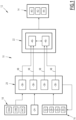
- FIG. 1 An example of a piloting system 10 according to the invention, preferably included in an aircraft 12, is illustrated schematically on the figure 1 .
- the aircraft 12 is for example a civil passenger transport aircraft, in particular a business plane, or a military plane.
- the aircraft 12 is equipped with control surfaces not shown, in particular pitch, roll and direction control surfaces, and air brakes.
- the aircraft 12 comprises at least one engine 14, for example a plurality of engines.
- the control system 10 comprises at least one throttle 16, a sensor system 18, a flight control unit 20, and an engine calculation unit 22.
- the piloting system 10 also preferably comprises a man-machine interface 24 capable of allowing a crew member to manually define at least one flight instruction to be imposed on the aircraft 12.
- the throttle 16 is operable by a pilot of the aircraft 12, and comprises at least one lever 26 and a base body 28.
- the lever 26 is movable relative to the base body 28.
- the lever 26 is movable angularly relative to the base body 28.
- the lever 26 is movable in translation relative to the base body 28.
- the lever 26 is able to be grasped by the pilot of the aircraft 12 to be moved relative to the base body 28. By such a movement of the lever 26, which corresponds to the actuation of the throttle lever 16, the pilot aims to control thrust of the aircraft.
- the throttle 16 also includes a motor 30 configured to move the lever 26 relative to the base body 28.
- the throttle 16 is configured to emit at least one signal representative of the position, for example angular, of the lever 26 relative to the base body 28.
- This signal is representative of the thrust that the pilot wishes to command.
- the throttle 16 comprises a sensor 32 configured to measure said position, for example angular, of the lever 26 and emit said representative signal.
- a sensor is for example an RVDT sensor (from the English “Rotary Variable Differential Transformer”).
- the acquisition of the position of the lever 26 relative to the base body 28 is redundant, the throttle 16 being configured to emit a plurality of signals representative of the same current position of the lever 26 relative to the base body 28.
- Said representative signal is for example an analog signal.
- said representative signal is for example a digital signal.
- An analog signal is here and subsequently defined as being formed by an electric current and/or an electric voltage varying within fixed limits.
- the analog signal presents a continuous variation, that is to say without steps or predefined levels.
- the analog signal is thus opposed to a digital signal, which uses quantification and coding of information.
- a digital signal circulates information represented by a finite number of determined discrete values, these discrete values being taken by at least one characteristic of the digital signal over time.
- the sensor system 18 is an aircraft flight parameter sensor system.
- Each sensor of the system 18 is able to measure a flight parameter of the aircraft 12 and to emit a signal representative of a current value of said flight parameter.
- the representative signal emitted by each sensor is analog or digital.
- the sensor system 18 comprises for example at least one inertial sensor 34A.
- Each inertial sensor 34A is for example an inertial unit possibly hybridized with a satellite positioning system, in particular GPS.
- Each inertial sensor 34A is capable of measuring current values of attitude, heading, route, speed vector, ground speed, acceleration of the aircraft 12, which form flight parameters of the aircraft 12.
- the sensor system 18 also includes, for example, at least one air data sensor 34B.
- Each 34B air data sensor is capable of carrying out speed and altitude measurements based on static or dynamic pressure measurements. It includes, for example, Pitot probes.
- Each air data sensor 34B is capable of measuring current values of air speed, Mach, badin, altitude, and total and static temperatures of the aircraft 12, which form flight parameters of the aircraft 12 .
- the sensor system 18 further comprises, for example, at least one attitude and reference heading sensor 34C.
- Each attitude and reference heading sensor 34C is for example made up of at least one gyrometer, at least one accelerometer, and/or at least one magnetometer which detect the accelerations and the magnetic fields experienced by the aircraft 12.
- Each attitude and reference heading sensor 34C is for example formed of micro-electromechanical systems (or MEMS in English).
- Each attitude and reference heading sensor 34C is also capable of obtaining current values of attitude, heading, course, and acceleration of the aircraft 12, which form flight parameters of the aircraft 12 .
- the sensors of the sensor system 18 are connected to the flight control unit 20, to deliver at any time, the current values of the flight parameters which they measure to the flight control unit 20, for example at a higher frequency or equal to 50 Hz.
- the flight control unit 20 is connected to the engine computing unit 22, to the sensors of the sensor system 18 and to the throttle 16.
- the flight control unit 20 is interposed between the throttle lever 16 and the engine calculation unit 22.
- the throttle lever 16 is interposed between the throttle lever 16 and the engine calculation unit 22.
- the flight control unit 20 is a digital flight command system (“Digital Flight Command System” or “DFCS” in English).
- DFCS Digital Flight Command System
- the flight control unit 20 is configured to receive at least the representative signal emitted by the throttle 16 and the signals emitted by the sensors of the sensor system 18.
- At least one of said signals is for example analog.
- at least the signal emitted by the throttle lever 16 is for example analog.
- the flight control unit 20 is configured to develop at least one thrust control vector obtained from at least one flight control law, having as input data at least the signals received from the throttle lever 16 and/or sensors of the sensor system 18. The flight control unit 20 is then configured to send a digital signal comprising the thrust control vector to the engine calculation unit 22.
- each thrust control vector is transported and binary encoded as bit strings.
- the flight control unit 20 is preferably arranged away from the or each engine 14 of the aircraft 12 so as not to be subject to an increase in temperature and/or vibrations coming from the or each engine 14.
- the flight control unit 20 comprises at least four redundant flight control computers 38.
- Each flight control computer 38 comprises, for example, a processor and a memory containing modules or software applications capable of being executed by the processor to carry out the functions of the computer 38 described below.
- each flight control computer 38 is implemented in the form of programmable logic components or dedicated integrated circuits, intended to perform the functions of the computer 38 described below.
- the flight control computers 38 are arranged for example away from the or each engine 14 as indicated above.
- Each flight control computer 38 is connected to the throttle 16 and to the sensor system 18.
- each flight control computer 38 is configured to receive at least the representative signal emitted by the throttle 16 and the signals emitted by the sensors of the sensor system 18.
- Each flight control computer 38 is configured to develop in parallel a thrust control vector from at least said flight control law, which has as input data at least said signals from the throttle 16 and /or sensors of the sensor system 18 received by the flight control computer 38.
- each flight control computer 38 is capable of implementing an analog/digital conversion of each analog signal received from the throttle 16 and/or the sensors of the sensor system 18.
- the input data of the control law are in particular data representative of the current values of the flight parameters measured by the sensors of the system 18 and, where appropriate, of the current position, for example angular, of the lever 26 of the throttle lever 16 operated by the pilot.
- control law preferably a plurality of control laws, is(are) predefined for the aircraft 12, for example as a function of an operating level of the equipment of the aircraft 12.
- Each control law is for example stored in the memory of each flight control computer 38.
- control vectors developed in parallel means control vectors having been respectively developed by the control computers. flight control 38 from the same values of the input data in the control law.
- control vectors developed in parallel by the flight control computers 38 are identical, except for an error in development on the part of at least one of the computers, and neglecting possible asynchronisms.
- Each control vector developed includes an actuation instruction for the control members 42, 44 of the engine 14, intended to be applied by the engine calculation unit 22.
- This actuation instruction contains the information enabling the engine computing unit 22 to know which control member(s) 42, 44 to actuate and to what extent.
- each control vector further comprises at least one additional piece of information, for example obtained from at least one of the sensors of the system 18.
- Each additional piece of information is preferably an anemometric parameter.
- each flight control computer 38 is configured to send a digital signal comprising the thrust control vector developed to the engine computer 22.
- thrust control vectors are developed successively, by each control computer 38, and are sent in the digital signal emitted by each control computer 38.
- each flight control computer 38 is capable of producing a thrust control vector, as described above, for example at a production frequency greater than or equal to 20 Hz.
- Each flight control computer 38 is suitable for sending the thrust control vector developed for example at a transfer frequency greater than or equal to 20 Hz.
- the flight control unit 20 is configured to control the motor 30 of the throttle 16, according to a predetermined control rule.
- the motor 30 is controlled according to the control rule to move the lever 26 relative to the base body 28.
- the control rule is stored in at least one of the memories.
- control rule is a function of each thrust vector developed.
- the motor 30 is then preferably controlled according to the control rule to move the lever 26, by a movement representative of the commanded thrust.
- control rule includes for example a correspondence table connecting a thrust control vector developed to an angle or a distance of the lever 26 relative to the base body 28.
- the controlled movement corresponds in particular to that which the lever 26 of the throttle 16 would have if the pilot had ordered a thrust corresponding to the developed control vector.
- the motorized movement of the lever 26 of the throttle 16 thus advantageously reflects the command developed by the flight control unit 20.
- the motorized movement of the lever 26 of the throttle 16 does not reflect the command developed by the flight control unit 20, but is chosen differently so as to ensure consistency between control of the aircraft engines and control of the aircraft. movement of the lever 26 of the lever 16.
- the control rule is for example independent of each thrust control vector developed.
- each flight control computer 38 is configured to generate a capsule comprising the developed control vector.
- control vectors produced successively by the same computer 38 are then sent in the form of a plurality of respective successive capsules.
- each digital signal emitted by the flight control computers 38 includes a plurality of capsules emitted at successive times.
- Each capsule then advantageously comprises a data producer identifier, a counter incremented each time data is generated, a functional data packet comprising said push control vector, and a data integrity check result relating to the identifier, the counter and the functional data packet.
- the identifier is for example a string of bits, making it possible to identify the flight control computer 38 having developed the thrust control vector of the capsule, and having generated the capsule.
- the identifier is thus characteristic of the flight control computer 38 which issued the capsule. More precisely, each flight control computer 38 is associated with a distinct producer identifier.
- the counter is a string of bits encoding a sequence number for preparing the functional data packet each time the functional data packet is produced.
- the counter is for example incremented individually each time a functional data packet is produced.
- the counter is preferably incremented independently of the transfer frequency.
- the counter makes it possible to associate, with each transmitted capsule, a data refresh measurement, which makes it possible to ensure that the functional data packet recovered by the engine computing unit 22 has been refreshed by the flight control computer. 38 and is therefore valid.
- the incrementing of the counter each time functional data is generated by the flight control computer 38 ensures that a refresh of the data has occurred, and not that a simple new transmission of data without refresh has occurred. .
- the counter is able to reset to zero when a predefined maximum of the counter has been reached.
- the functional data packet includes for example only a single elaborated thrust control vector.
- a respective capsule is generated for each thrust control vector.
- the integrity check result is a string of bits encoding a check number calculated by mathematical processing, from a functional representation integrating the capsule identifier, the capsule counter, and the functional data packet of the capsule.
- the integrity check result aims to detect capsule corruption.
- such corruption of the capsule can occur in the event of a memory problem within the flight control computer 38 and/or in the event of electromagnetic disturbance due to the environment of the computer 38 or the connection with the control unit. engine calculation 22.
- the integrity check result is the result of a checksum, or a cyclic redundancy code (CRC).
- CRC cyclic redundancy code
- the integrity calculation result is obtained by a MIL-STD-1760 checksum, or by a CRC-32K/6.4 cyclic redundancy code.
- the mathematical processing is for example an algorithm chosen according to the security objectives to be achieved, a minimum/maximum length of the data packet, the identifier, the counter, and the reliability of the data link, in term bit error rate (in English BER, for “Bit Error Rate”).
- bit error rate in English BER, for “Bit Error Rate”.
- the engine calculation center 22 is connected to the equipment of the engine 14.
- the equipment of the engine 14 includes sensors 40 capable of monitoring a state of the engine 14, and also includes control members 42, 44 such as valves 42 and actuators 44, for example hydraulic and electric.
- the engine computing unit 22 is a digital regulation system for the engine 14, preferably of the type having full authority over the control of the engine 14 (“Full Authority Digital Engine Control” or “FADEC” in English).
- the engine computing unit 22 is then preferably configured to have full authority over the control of the motor 14, so that each control member 42, 44 of the motor 14 is then, for example, controlled only by signals emitted by the computing unit. engine 22.
- the engine calculation unit 22 is close to the engine 14. In particular, by “near”, we mean that the engine calculation unit 22 is capable of being subject to an increase in temperature and/or vibrations coming from the engine 14.
- the engine computing unit 22 is preferably in contact with ambient air and is cooled for example by a cooling system by drawing off an air flow.
- the engine computing unit 22 is configured to receive each digital signal sent by the flight control unit 20, and to control the thrust parameters of the engine 14 as a function of at least one thrust control vector included. in the digital signal, by actuating control members 42, 44 of the motor 14.
- the thrust parameters controlled by the engine computer 22 include for example at least one fuel flow, one ignition, and one fuel/air mixture proportion.
- the engine computing unit 22 comprises at least two redundant engine computers 46 (or “Electronic Engine Controller”).
- Each engine computer 46 comprises, for example, a processor and a memory containing modules or software applications capable of being executed by the processor to carry out the functions of the engine computer 46 described below.
- each engine computer 46 is implemented in the form of components programmable logic or dedicated integrated circuits, intended to carry out the functions of the engine computer 46 described below.
- a first of the engine computers 46 is only directly connected to a part, here two, of the flight control computers 38.
- the first of the engine computers 46 is connected by at least one digital data transfer link 48 two of the flight control computers 38.
- the first of the engine computers 46 is connected to said two flight control computers 38 by two different digital data transfer links 48.
- the second of the engine computers 46 is only directly connected to the others, here only to the other two, of the flight control computers 38.
- the second of the engine computers 46 is connected by at least one other connection 48 transfer of digital data to the other two of the flight control computers 38.
- the second of the engine computers 46 is connected to said two other flight control computers 38 by two different digital data transfer links 48.
- a digital data transfer link 48 connects said flight control computer 38 to only one of the engine computers 46.
- the digital data transfer links 48 then present each an input connected to one of the flight control computers 38, an output connected to one of the engine computers 46, and a link connecting the input to the output.
- Each engine computer 46 is capable of receiving each control vector, in particular each capsule, sent by the flight control computers 38 to which it is connected, for example at a reception frequency greater than or equal to 20 Hz.
- the two engine computers 46 are also connected to each other. As illustrated on the figure 1 , they are in particular connected for example internally to the engine computing unit 22.
- control vectors are also configured to communicate to each other the control vectors respectively received, this communication being for example internal to the engine computer 22.
- the engine computers 46 are configured to communicate the capsules respectively received to each other.
- Each engine computer 46 thus receives directly from the flight control unit 20 or indirectly through the other engine computer 46 the redundant thrust control vectors developed in parallel by each of the flight control computers 38.
- This architecture notably improves transmission security.
- Each engine computer 46 is configured to make, at each instant, a selection among the control vectors developed in parallel by each flight control computer 38, and to control said thrust parameters of the engine 14 as a function of the selected control vector.
- control members 42, 44 of the motor 14 are actuated by the engine computing unit 22 as a function of the selected control vector, in particular as a function of the actuation instruction contained in the selected control vector.
- the engine calculation unit 22 emits corresponding signals to the control elements 42, 44.
- each engine computer 46 is configured to recover the identifier, the counter, the functional data packet, and the integrity check result of the capsules received containing the control vectors developed in parallel. These capsules are referred to as “parallel capsules received” hereinafter.
- Each engine computer 46 is then configured to implement at least one identification check of the identifier, at least one validity check of the counter and at least one integrity check of said control result for each of the parallel capsules received.
- Each engine computer 46 is configured to select the thrust control vector of one of said parallel capsules received at least if the identifier of the capsule is correct, if the capsule is valid and if the capsule is intact.
- this selection is carried out as soon as, for one of said parallel capsules received, the identifier of the capsule is correct, the capsule is valid and the capsule is intact.
- each engine computer 46 in parallel, and as soon as a control vector is selected by one of the engine computers 46, the engine computer 22 applies the actuation instruction of said selected vector.
- the engine computer 46 is able to exclude the data coming from the capsule. In particular, a thrust control vector contained in such a capsule will not be selected and will not be applied by the engine computer 46.
- the engine computer 46 is able to check, from the identifier, whether the data received actually comes from the expected flight control computer 38.
- the engine computer 46 is configured to determine an identification state of the capsule between a correct identification state and an incorrect identification state.
- This identification state is determined as a function of the identifier retrieved from the capsule received and an expected identifier for the capsule received, for example from a predefined semantics and/or a correspondence table.
- the engine computer 46 is preferably configured to determine a validity state of the capsule between a valid state and an invalid state, by checking their refresh using the extracted counter.
- the engine computer 46 is configured to determine a counter increment from the recovered counter and from the counter of another capsule previously received by the engine computer 46.
- the engine computer 46 is configured to determine the validity state of the capsule based on consistency of the counter increment.
- the motor computer 46 is suitable for example for calculating the increment between the counter extracted from the capsule received, and the counter of the capsule received just before.
- the engine computer 46 is able to determine that the functional data present in the capsule is indeed refreshed data and to place the capsule in the valid state.
- the increment is considered coherent by the engine computer 46 at least if it is unitary.
- the computer is configured to determine a consistency of the increment calculated as a function of the frequency of production of the capsules by the flight control computer 38, of the frequency of transfer of the capsules by the flight control computer 38, and/or the frequency of reception of the capsules by the engine computer 46.
- the engine computer 46 is able to consider as coherent an increment of zero counter on a determined number of capsules, such a number being calculated for example according to the frequencies of preparation, transfer or acquisition of the capsules.
- the motor computer 46 is capable of considering a counter increment greater than one as coherent.
- the engine computer 46 is able to memorize the counter of each capsule just received, to allow an increment calculation when receiving the next capsule.
- the engine computer 46 is able to determine that the functional data present in the capsule are indeed refreshed data which can be used by the engine computer 46, and to pass the capsule in valid state; or if on the contrary, if the data is not refreshed or if intermediate data not received is missing, to put the capsule in the invalid state.
- the engine computer 46 is preferably configured to determine a state of integrity of the capsule data between an intact state and a corrupt state.
- the engine computer 46 is configured to establish a new integrity check result from the identifier, the counter and the functional data packet recovered in the capsule received, and to compare the new check result. integrity to the integrity check result retrieved in the capsule.
- the engine computer 46 is capable of applying the same mathematical processing as that implemented by the flight control computer 38, to establish the new integrity check result.
- the engine computer 46 is capable of determining that the capsule comprising the identifier, the counter and the data packet is in the integrity state, if the new integrity check result that it has calculated from the data received is identical to the integrity check result extracted from the capsule.
- the engine computer 46 is capable of determining that the capsule is in a corrupted state, if the new integrity check result that it has calculated from the data received is different from the integrity check result extracted from the capsule.
- the engine computer 46 When a capsule is in the incorrect identification state, in the corrupted state and/or in the invalid state, the engine computer 46 is able to exclude the data coming from the capsule.
- the engine computer 46 is also then preferably capable of implementing a reset phase, for a given reset duration corresponding for example to the resetting of one of the computers or to the stopping of a transient failure.
- the engine computer 46 is able to definitively stop the rearming and to declare the computer flight control 38 transmitting the faulty capsules.
- the engine computer 46 is then configured to no longer take into account the digital signal sent by said flight control computer 38.
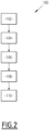
- a method 100 for piloting the aircraft using the piloting system 10 described above will now be described, with reference to the figure 2 .
- the method 100 comprises the provision 102 of said control system 10.
- the method 100 comprises the development 104, by the flight control unit 20, of at least one thrust control vector obtained from the flight control law, having as input data at least the signals received of the throttle 16 and/or the sensors of the sensor system 18.
- the method 100 subsequently comprises sending 106 a digital signal comprising the thrust control vector to the engine calculation unit 22.
- processing and sending steps 104, 106 are implemented by the flight control unit 20, preferably in the manner described above in more detail for the control system 10.
- the method 100 then comprises the reception 108 of the digital signal, by the engine calculation unit 22, and the control 110 of the thrust parameters of the engine 14 as a function of the thrust control vector.
- reception and control steps 108, 110 are implemented by the engine computing unit 22, preferably in the manner described above in more detail for the control system 10.
- each engine computer 46 is not only made as soon as, for one of the capsules, the identifier of the capsule is correct, the capsule is valid and the capsule is intact.
- the selection is alternatively made by a centralized vote carried out on the parallel capsules received. Centralized voting is then carried out, for example, by majority or weighted average or median determination algorithms.
- control vectors are not encapsulated in the digital signal.
- Each engine computer 46 is then configured to select one of the parallel vectors received, for example by centralized voting on the parallel vectors received. Centralized voting is for example carried out by majority or weighted average or median determination algorithms.
- each control vector developed does not include an anemometric parameter.
- Each flight control computer 38 is for example then configured to send current values of anemometric parameters in specific capsules included in the digital signal. These capsules containing the anemometric parameters are for example transmitted at a different frequency from those containing the thrust control vectors.
- the flight control unit 20, and in particular each flight control computer 38 is also configured to process the signals received from the throttle 16 and/or or the sensor system 18 in order to apply overspeed protection and/or avoidance of the aircraft stalling.
- the flight control unit 20, and in particular each flight control computer 38 is capable of determining automatic protections at least to prevent overspeed and/or stalling.
- Each flight control law then has as input data at least said signals from the throttle 16 and/or sensors of the sensor system 18 received, and the determined protections.
- the flight control unit 20 modulates the commands entered by the pilot when he activates the throttle 16.
- the flight control unit 20 has an automatic thrust mode, and a manual thrust mode.
- each thrust control vector is developed from the signals received from the throttle 16 and the sensors of the sensor system 18.
- Each flight control computer 38 then takes into account in particular an actuation of the throttle 16 by the pilot in the development of the thrust control vectors.
- the or each thrust control vector is developed solely from the signals received from the sensors of the sensor system 18 as a function of at least one chosen flight instruction, for example as a function of a plurality flight instructions.
- an actuation of the throttle lever 16 by the pilot is not taken into account in the development of the thrust control vectors.
- Each flight instruction is for example defined manually by a member of the crew via the man-machine interface 24.
- Each flight instruction is for example a heading and/or a route and/or an air speed and /or a Mach, and/or an altitude, and/or an ascent or descent slope, and/or a climb instruction as high as possible without decelerating, or a descent instruction as low as possible without accelerating.
- the aircraft 12 is for example a drone.
- the aircraft 12 then has no throttle.
- control system 10 is robust to analog acquisition noise from the throttle 16.
- the distance between the throttle 16 and the motor 14 no longer has an impact on the noises from the thrust control.
- the engine calculation unit 22 no longer requires a dedicated analog signal acquisition stage to receive the thrust command.
- the reliability of the system is therefore improved to the extent that a digital link is less dependent on the thermal environment and vibrations generated by the motor 14 than an analog connection.
- the flight control unit 20 also makes it possible to circulate additional information to the actuation instruction of the control members 42, 44 of the engine 14 (pilot controls, airspeed parameters), and therefore to eliminate additional digital links in the aircraft. A weight gain results and the consistency of the information used in the aircraft is improved.
- the loss of motorization of the throttle lever 16 no longer leads to the loss of the automatic thrust control function. More generally, the total loss of the joystick function no longer implies an inability to control the motor.
- the invention unexpectedly crosses the certification requirements of three different fields, namely those relating to the automation of thrust, the calculation of thrust control and the processing of the throttle 16.
Landscapes
- Engineering & Computer Science (AREA)
- Aviation & Aerospace Engineering (AREA)
- Automation & Control Theory (AREA)
- Combined Controls Of Internal Combustion Engines (AREA)
- Control Of Vehicle Engines Or Engines For Specific Uses (AREA)
Applications Claiming Priority (2)
| Application Number | Priority Date | Filing Date | Title |
|---|---|---|---|
| FR2100288A FR3118807A1 (fr) | 2021-01-13 | 2021-01-13 | Systeme de pilotage d'aeronef, aeronef et procede associes |
| EP22151182.7A EP4029784B1 (de) | 2021-01-13 | 2022-01-12 | Vorrichtung zum steuern eines luftfahrzeugs, entsprechendes luftfahrzeug und verfahren |
Related Parent Applications (2)
| Application Number | Title | Priority Date | Filing Date |
|---|---|---|---|
| EP22151182.7A Division EP4029784B1 (de) | 2021-01-13 | 2022-01-12 | Vorrichtung zum steuern eines luftfahrzeugs, entsprechendes luftfahrzeug und verfahren |
| EP22151182.7A Division-Into EP4029784B1 (de) | 2021-01-13 | 2022-01-12 | Vorrichtung zum steuern eines luftfahrzeugs, entsprechendes luftfahrzeug und verfahren |
Publications (3)
| Publication Number | Publication Date |
|---|---|
| EP4324746A2 true EP4324746A2 (de) | 2024-02-21 |
| EP4324746A3 EP4324746A3 (de) | 2024-04-24 |
| EP4324746B1 EP4324746B1 (de) | 2025-12-31 |
Family
ID=76375115
Family Applications (2)
| Application Number | Title | Priority Date | Filing Date |
|---|---|---|---|
| EP24151080.9A Active EP4324746B1 (de) | 2021-01-13 | 2022-01-12 | Flugzeugsteuerungssystem, flugzeug und verfahren dafür |
| EP22151182.7A Active EP4029784B1 (de) | 2021-01-13 | 2022-01-12 | Vorrichtung zum steuern eines luftfahrzeugs, entsprechendes luftfahrzeug und verfahren |
Family Applications After (1)
| Application Number | Title | Priority Date | Filing Date |
|---|---|---|---|
| EP22151182.7A Active EP4029784B1 (de) | 2021-01-13 | 2022-01-12 | Vorrichtung zum steuern eines luftfahrzeugs, entsprechendes luftfahrzeug und verfahren |
Country Status (6)
| Country | Link |
|---|---|
| US (2) | US12252236B2 (de) |
| EP (2) | EP4324746B1 (de) |
| BR (1) | BR102022000583A2 (de) |
| CA (1) | CA3145495A1 (de) |
| ES (2) | ES3064369T3 (de) |
| FR (1) | FR3118807A1 (de) |
Families Citing this family (3)
| Publication number | Priority date | Publication date | Assignee | Title |
|---|---|---|---|---|
| CN116661331B (zh) * | 2023-08-02 | 2023-09-26 | 成都正扬博创电子技术有限公司 | 一种利用软硬件协同的多余度飞控计算机系统 |
| FR3157584B1 (fr) * | 2023-12-22 | 2025-12-26 | Thales Sa | Système de gestion d’entrées/sorties d’au moins une application avionique et procédé de vérification de fonctionnement d’un tel système |
| TR2024007098A1 (tr) * | 2024-06-04 | 2025-12-22 | Tusas Tuerk Havacilik Ve Uzay Sanayii Anonim Sirketi | Bir kontrol yönetimi sistemi. |
Family Cites Families (7)
| Publication number | Priority date | Publication date | Assignee | Title |
|---|---|---|---|---|
| US6345603B1 (en) * | 2000-04-11 | 2002-02-12 | Visteon Global Technologies, Inc. | Throttle control for vehicle using redundant throttle signals |
| US7949440B2 (en) * | 2006-12-22 | 2011-05-24 | Embraer-Empresa Brasileira De Aeronautica S.A. | Aircraft cruise speed control |
| US10137997B2 (en) * | 2013-08-29 | 2018-11-27 | Bombardier Inc. | Electronic throttle system for an aircraft |
| US10414512B2 (en) * | 2014-10-01 | 2019-09-17 | Sikorsky Aircraft Corporation | Power management between a propulsor and a coaxial rotor of a helicopter |
| EP3325342A4 (de) * | 2015-07-20 | 2019-02-27 | Sikorsky Aircraft Corporation | Steuerungssystem für einen motorneustart eines drehflüglers während des fluges |
| IL262426B2 (en) * | 2018-10-14 | 2024-08-01 | Israel Aerospace Ind Ltd | Systems and methods for controlling aircraft engines |
| FR3088897A1 (fr) * | 2018-11-26 | 2020-05-29 | Airbus Operations (S.A.S.) | Système de commande de vol d’un aéronef. |
-
2021
- 2021-01-13 FR FR2100288A patent/FR3118807A1/fr active Pending
-
2022
- 2022-01-12 EP EP24151080.9A patent/EP4324746B1/de active Active
- 2022-01-12 CA CA3145495A patent/CA3145495A1/fr active Pending
- 2022-01-12 ES ES24151080T patent/ES3064369T3/es active Active
- 2022-01-12 BR BR102022000583-4A patent/BR102022000583A2/pt unknown
- 2022-01-12 EP EP22151182.7A patent/EP4029784B1/de active Active
- 2022-01-12 ES ES22151182T patent/ES2978944T3/es active Active
- 2022-01-13 US US17/574,677 patent/US12252236B2/en active Active
-
2024
- 2024-12-19 US US18/987,088 patent/US20250115351A1/en active Pending
Also Published As
| Publication number | Publication date |
|---|---|
| ES2978944T3 (es) | 2024-09-23 |
| EP4324746B1 (de) | 2025-12-31 |
| EP4029784B1 (de) | 2024-03-13 |
| CA3145495A1 (fr) | 2022-07-13 |
| US20250115351A1 (en) | 2025-04-10 |
| ES3064369T3 (en) | 2026-04-24 |
| BR102022000583A2 (pt) | 2022-07-26 |
| EP4029784A1 (de) | 2022-07-20 |
| EP4324746A3 (de) | 2024-04-24 |
| US20220219809A1 (en) | 2022-07-14 |
| US12252236B2 (en) | 2025-03-18 |
| FR3118807A1 (fr) | 2022-07-15 |
Similar Documents
| Publication | Publication Date | Title |
|---|---|---|
| EP4029784B1 (de) | Vorrichtung zum steuern eines luftfahrzeugs, entsprechendes luftfahrzeug und verfahren | |
| FR3066755B1 (fr) | Procede et dispositif de surveillance et d'estimation de parametres relatifs au vol d'un aeronef. | |
| US8761970B2 (en) | Alternative method to determine the air mass state of an aircraft and to validate and augment the primary method | |
| FR2916530A1 (fr) | Procede et dispositif pour surveiller une indication de position d'un aeronef. | |
| EP2551191B1 (de) | Verfahren und Vorrichtung zum Erkennen des Ausfahrens einer Steuerfläche eines Luftfahrzeugs | |
| EP2048475B1 (de) | Verfahren zur Bestimmung der Lage, Position und Geschwindigkeit eines beweglichen Geräts | |
| FR2911972A1 (fr) | Procede de surveillance de moteurs d'avion | |
| FR2913780A1 (fr) | Procede et dispositif d'aide au guidage d'un aeronef | |
| EP3637207B1 (de) | Steuerungssystem eines über eine graphische schnittstelle gesteuerten systems, und entsprechendes verfahren | |
| EP2957975A1 (de) | Steuerverfahren und -vorrichtung mindestens eines kontrollsystems eines stellglieds eines luftfahrzeugs, entsprechendes computerprogramm-produkt und entsprechendes luftfahrzeug | |
| EP1679567A2 (de) | Architektur eines Bordsystems zur Unterstützung der Steuerung von Luftschiffen | |
| FR3022354A1 (fr) | Procede de prediction d'une trajectoire court terme d'un aeronef, produit programme d'ordinateur, disponible de prediction, procede de guidage, systeme de guidage et aeronef associes | |
| FR3007841A1 (fr) | Procede de detection d'une panne d'au moins un capteur present sur un aeronef, mettant en oeuvre une boucle baro-inertielle et systeme associe | |
| FR3042612A1 (fr) | Procede et dispositif de detection de pannes oscillatoires dans une chaine d'asservissement en position d'une gouverne d'aeronef. | |
| FR3094785A1 (fr) | Unite et systeme de reference intertielle a integrite amelioree et procedes de controle d'integrite associes | |
| EP3742249B1 (de) | Verfahren und gesichertes system für positionskontrolle eines luftfahrzeugs in bezug auf ein genehmigtes fluggebiet | |
| EP4300053B1 (de) | Verfahren zum trainieren mindestens eines modells der künstlichen intelligenz zur schätzung der masse eines flugzeugs während des flugs auf der grundlage von nutzungsdaten | |
| FR3044634A1 (fr) | Procede et dispositif de pilotage d'un aeronef | |
| EP0007270A1 (de) | Selbstüberwachende Steuerung eines Prozesses | |
| EP4030330A1 (de) | System zur sicheren übertragung von digitalen luftfahrzeugdaten, das systeme zur erzeugung redundanter daten umfasst, entsprechende anordnung und entsprechendes verfahren | |
| FR3101669A1 (fr) | Dispositif, procédé et programme d’ordinateur de suivi de moteur d’aéronef | |
| EP4437349A1 (de) | Verfahren zur begrenzung der baro-inertialen geschwindigkeitskorrektur und zugehöriges system | |
| EP3072019B1 (de) | Kritisches system und zugehöriges überwachungsverfahren | |
| FR2903379A1 (fr) | Convertisseur de commande de facteur de charge en consigne d'ecart d'assiette longitudinale | |
| WO2023094761A1 (fr) | Procédé de détection de défaillance d'un baro-altimètre dans une boucle baro-inertielle et système associé |
Legal Events
| Date | Code | Title | Description |
|---|---|---|---|
| PUAI | Public reference made under article 153(3) epc to a published international application that has entered the european phase |
Free format text: ORIGINAL CODE: 0009012 |
|
| STAA | Information on the status of an ep patent application or granted ep patent |
Free format text: STATUS: REQUEST FOR EXAMINATION WAS MADE |
|
| 17P | Request for examination filed |
Effective date: 20240110 |
|
| AC | Divisional application: reference to earlier application |
Ref document number: 4029784 Country of ref document: EP Kind code of ref document: P |
|
| AK | Designated contracting states |
Kind code of ref document: A2 Designated state(s): AL AT BE BG CH CY CZ DE DK EE ES FI FR GB GR HR HU IE IS IT LI LT LU LV MC MK MT NL NO PL PT RO RS SE SI SK SM TR |
|
| REG | Reference to a national code |
Ref country code: DE Ref legal event code: R079 Ref country code: DE Ref legal event code: R079 Ref document number: 602022028213 Country of ref document: DE Free format text: PREVIOUS MAIN CLASS: B64D0031060000 Ipc: B64D0031040000 |
|
| PUAL | Search report despatched |
Free format text: ORIGINAL CODE: 0009013 |
|
| AK | Designated contracting states |
Kind code of ref document: A3 Designated state(s): AL AT BE BG CH CY CZ DE DK EE ES FI FR GB GR HR HU IE IS IT LI LT LU LV MC MK MT NL NO PL PT RO RS SE SI SK SM TR |
|
| RIC1 | Information provided on ipc code assigned before grant |
Ipc: B64C 13/50 20060101ALN20240319BHEP Ipc: B64D 31/06 20240101ALI20240319BHEP Ipc: B64D 31/14 20060101ALI20240319BHEP Ipc: B64D 31/04 20060101AFI20240319BHEP |
|
| GRAP | Despatch of communication of intention to grant a patent |
Free format text: ORIGINAL CODE: EPIDOSNIGR1 |
|
| STAA | Information on the status of an ep patent application or granted ep patent |
Free format text: STATUS: GRANT OF PATENT IS INTENDED |
|
| RIC1 | Information provided on ipc code assigned before grant |
Ipc: B64D 31/04 20060101AFI20250911BHEP Ipc: B64D 31/14 20060101ALI20250911BHEP Ipc: B64D 31/06 20240101ALI20250911BHEP Ipc: B64C 13/50 20060101ALN20250911BHEP |
|
| INTG | Intention to grant announced |
Effective date: 20250924 |
|
| GRAS | Grant fee paid |
Free format text: ORIGINAL CODE: EPIDOSNIGR3 |
|
| GRAA | (expected) grant |
Free format text: ORIGINAL CODE: 0009210 |
|
| STAA | Information on the status of an ep patent application or granted ep patent |
Free format text: STATUS: THE PATENT HAS BEEN GRANTED |
|
| AC | Divisional application: reference to earlier application |
Ref document number: 4029784 Country of ref document: EP Kind code of ref document: P |
|
| AK | Designated contracting states |
Kind code of ref document: B1 Designated state(s): AL AT BE BG CH CY CZ DE DK EE ES FI FR GB GR HR HU IE IS IT LI LT LU LV MC MK MT NL NO PL PT RO RS SE SI SK SM TR |
|
| REG | Reference to a national code |
Ref country code: CH Ref legal event code: F10 Free format text: ST27 STATUS EVENT CODE: U-0-0-F10-F00 (AS PROVIDED BY THE NATIONAL OFFICE) Effective date: 20251231 Ref country code: GB Ref legal event code: FG4D Free format text: NOT ENGLISH |
|
| REG | Reference to a national code |
Ref country code: DE Ref legal event code: R096 Ref document number: 602022028213 Country of ref document: DE |
|
| PGFP | Annual fee paid to national office [announced via postgrant information from national office to epo] |
Ref country code: FR Payment date: 20251209 Year of fee payment: 5 |
|
| REG | Reference to a national code |
Ref country code: IE Ref legal event code: FG4D Free format text: LANGUAGE OF EP DOCUMENT: FRENCH |
|
| PGFP | Annual fee paid to national office [announced via postgrant information from national office to epo] |
Ref country code: GB Payment date: 20260127 Year of fee payment: 5 |
|
| PGFP | Annual fee paid to national office [announced via postgrant information from national office to epo] |
Ref country code: ES Payment date: 20260209 Year of fee payment: 5 |
|
| REG | Reference to a national code |
Ref country code: LT Ref legal event code: MG9D |
|
| PG25 | Lapsed in a contracting state [announced via postgrant information from national office to epo] |
Ref country code: NO Free format text: LAPSE BECAUSE OF FAILURE TO SUBMIT A TRANSLATION OF THE DESCRIPTION OR TO PAY THE FEE WITHIN THE PRESCRIBED TIME-LIMIT Effective date: 20260331 |
|
| PGFP | Annual fee paid to national office [announced via postgrant information from national office to epo] |
Ref country code: DE Payment date: 20260114 Year of fee payment: 5 |
|
| PG25 | Lapsed in a contracting state [announced via postgrant information from national office to epo] |
Ref country code: HR Free format text: LAPSE BECAUSE OF FAILURE TO SUBMIT A TRANSLATION OF THE DESCRIPTION OR TO PAY THE FEE WITHIN THE PRESCRIBED TIME-LIMIT Effective date: 20251231 Ref country code: FI Free format text: LAPSE BECAUSE OF FAILURE TO SUBMIT A TRANSLATION OF THE DESCRIPTION OR TO PAY THE FEE WITHIN THE PRESCRIBED TIME-LIMIT Effective date: 20251231 |
|
| PGFP | Annual fee paid to national office [announced via postgrant information from national office to epo] |
Ref country code: AT Payment date: 20260301 Year of fee payment: 5 |
|
| PGFP | Annual fee paid to national office [announced via postgrant information from national office to epo] |
Ref country code: IT Payment date: 20260108 Year of fee payment: 5 |
|
| PG25 | Lapsed in a contracting state [announced via postgrant information from national office to epo] |
Ref country code: RS Free format text: LAPSE BECAUSE OF FAILURE TO SUBMIT A TRANSLATION OF THE DESCRIPTION OR TO PAY THE FEE WITHIN THE PRESCRIBED TIME-LIMIT Effective date: 20260331 |
|
| REG | Reference to a national code |
Ref country code: ES Ref legal event code: FG2A Ref document number: 3064369 Country of ref document: ES Kind code of ref document: T3 Effective date: 20260424 |
|
| PG25 | Lapsed in a contracting state [announced via postgrant information from national office to epo] |
Ref country code: LV Free format text: LAPSE BECAUSE OF FAILURE TO SUBMIT A TRANSLATION OF THE DESCRIPTION OR TO PAY THE FEE WITHIN THE PRESCRIBED TIME-LIMIT Effective date: 20251231 |
|
| PG25 | Lapsed in a contracting state [announced via postgrant information from national office to epo] |
Ref country code: BG Free format text: LAPSE BECAUSE OF FAILURE TO SUBMIT A TRANSLATION OF THE DESCRIPTION OR TO PAY THE FEE WITHIN THE PRESCRIBED TIME-LIMIT Effective date: 20251231 |
|
| REG | Reference to a national code |
Ref country code: NL Ref legal event code: MP Effective date: 20251231 |