EP4324683A1 - Battery compartment, chassis and vehicle - Google Patents
Battery compartment, chassis and vehicle Download PDFInfo
- Publication number
- EP4324683A1 EP4324683A1 EP22889185.9A EP22889185A EP4324683A1 EP 4324683 A1 EP4324683 A1 EP 4324683A1 EP 22889185 A EP22889185 A EP 22889185A EP 4324683 A1 EP4324683 A1 EP 4324683A1
- Authority
- EP
- European Patent Office
- Prior art keywords
- battery
- battery compartment
- frame
- protrusion
- recess
- Prior art date
- Legal status (The legal status is an assumption and is not a legal conclusion. Google has not performed a legal analysis and makes no representation as to the accuracy of the status listed.)
- Pending
Links
- 238000003780 insertion Methods 0.000 claims description 28
- 230000037431 insertion Effects 0.000 claims description 28
- 239000000725 suspension Substances 0.000 claims description 20
- 239000006096 absorbing agent Substances 0.000 claims description 16
- 230000035939 shock Effects 0.000 claims description 16
- 230000008439 repair process Effects 0.000 abstract description 10
- 239000000853 adhesive Substances 0.000 abstract description 4
- 230000001070 adhesive effect Effects 0.000 abstract description 4
- 238000010586 diagram Methods 0.000 description 15
- 229910001416 lithium ion Inorganic materials 0.000 description 3
- HBBGRARXTFLTSG-UHFFFAOYSA-N Lithium ion Chemical compound [Li+] HBBGRARXTFLTSG-UHFFFAOYSA-N 0.000 description 2
- 230000008859 change Effects 0.000 description 2
- 230000010354 integration Effects 0.000 description 2
- 230000013011 mating Effects 0.000 description 2
- VNWKTOKETHGBQD-UHFFFAOYSA-N methane Chemical compound C VNWKTOKETHGBQD-UHFFFAOYSA-N 0.000 description 2
- 238000000926 separation method Methods 0.000 description 2
- JLVVSXFLKOJNIY-UHFFFAOYSA-N Magnesium ion Chemical compound [Mg+2] JLVVSXFLKOJNIY-UHFFFAOYSA-N 0.000 description 1
- FKNQFGJONOIPTF-UHFFFAOYSA-N Sodium cation Chemical compound [Na+] FKNQFGJONOIPTF-UHFFFAOYSA-N 0.000 description 1
- JDZCKJOXGCMJGS-UHFFFAOYSA-N [Li].[S] Chemical compound [Li].[S] JDZCKJOXGCMJGS-UHFFFAOYSA-N 0.000 description 1
- 230000004308 accommodation Effects 0.000 description 1
- 230000009471 action Effects 0.000 description 1
- 238000007599 discharging Methods 0.000 description 1
- 239000000446 fuel Substances 0.000 description 1
- 239000002737 fuel gas Substances 0.000 description 1
- 239000007789 gas Substances 0.000 description 1
- 239000007788 liquid Substances 0.000 description 1
- 229910001425 magnesium ion Inorganic materials 0.000 description 1
- 230000007246 mechanism Effects 0.000 description 1
- 238000012986 modification Methods 0.000 description 1
- 230000004048 modification Effects 0.000 description 1
- 239000003345 natural gas Substances 0.000 description 1
- 238000004806 packaging method and process Methods 0.000 description 1
- 229910001415 sodium ion Inorganic materials 0.000 description 1
- 238000006467 substitution reaction Methods 0.000 description 1
Images


Classifications
-
- H—ELECTRICITY
- H01—ELECTRIC ELEMENTS
- H01M—PROCESSES OR MEANS, e.g. BATTERIES, FOR THE DIRECT CONVERSION OF CHEMICAL ENERGY INTO ELECTRICAL ENERGY
- H01M50/00—Constructional details or processes of manufacture of the non-active parts of electrochemical cells other than fuel cells, e.g. hybrid cells
- H01M50/20—Mountings; Secondary casings or frames; Racks, modules or packs; Suspension devices; Shock absorbers; Transport or carrying devices; Holders
- H01M50/249—Mountings; Secondary casings or frames; Racks, modules or packs; Suspension devices; Shock absorbers; Transport or carrying devices; Holders specially adapted for aircraft or vehicles, e.g. cars or trains
-
- B—PERFORMING OPERATIONS; TRANSPORTING
- B60—VEHICLES IN GENERAL
- B60L—PROPULSION OF ELECTRICALLY-PROPELLED VEHICLES; SUPPLYING ELECTRIC POWER FOR AUXILIARY EQUIPMENT OF ELECTRICALLY-PROPELLED VEHICLES; ELECTRODYNAMIC BRAKE SYSTEMS FOR VEHICLES IN GENERAL; MAGNETIC SUSPENSION OR LEVITATION FOR VEHICLES; MONITORING OPERATING VARIABLES OF ELECTRICALLY-PROPELLED VEHICLES; ELECTRIC SAFETY DEVICES FOR ELECTRICALLY-PROPELLED VEHICLES
- B60L50/00—Electric propulsion with power supplied within the vehicle
- B60L50/50—Electric propulsion with power supplied within the vehicle using propulsion power supplied by batteries or fuel cells
- B60L50/60—Electric propulsion with power supplied within the vehicle using propulsion power supplied by batteries or fuel cells using power supplied by batteries
- B60L50/66—Arrangements of batteries
-
- B—PERFORMING OPERATIONS; TRANSPORTING
- B60—VEHICLES IN GENERAL
- B60K—ARRANGEMENT OR MOUNTING OF PROPULSION UNITS OR OF TRANSMISSIONS IN VEHICLES; ARRANGEMENT OR MOUNTING OF PLURAL DIVERSE PRIME-MOVERS IN VEHICLES; AUXILIARY DRIVES FOR VEHICLES; INSTRUMENTATION OR DASHBOARDS FOR VEHICLES; ARRANGEMENTS IN CONNECTION WITH COOLING, AIR INTAKE, GAS EXHAUST OR FUEL SUPPLY OF PROPULSION UNITS IN VEHICLES
- B60K1/00—Arrangement or mounting of electrical propulsion units
- B60K1/04—Arrangement or mounting of electrical propulsion units of the electric storage means for propulsion
-
- B—PERFORMING OPERATIONS; TRANSPORTING
- B60—VEHICLES IN GENERAL
- B60L—PROPULSION OF ELECTRICALLY-PROPELLED VEHICLES; SUPPLYING ELECTRIC POWER FOR AUXILIARY EQUIPMENT OF ELECTRICALLY-PROPELLED VEHICLES; ELECTRODYNAMIC BRAKE SYSTEMS FOR VEHICLES IN GENERAL; MAGNETIC SUSPENSION OR LEVITATION FOR VEHICLES; MONITORING OPERATING VARIABLES OF ELECTRICALLY-PROPELLED VEHICLES; ELECTRIC SAFETY DEVICES FOR ELECTRICALLY-PROPELLED VEHICLES
- B60L50/00—Electric propulsion with power supplied within the vehicle
- B60L50/50—Electric propulsion with power supplied within the vehicle using propulsion power supplied by batteries or fuel cells
- B60L50/60—Electric propulsion with power supplied within the vehicle using propulsion power supplied by batteries or fuel cells using power supplied by batteries
- B60L50/64—Constructional details of batteries specially adapted for electric vehicles
-
- B—PERFORMING OPERATIONS; TRANSPORTING
- B62—LAND VEHICLES FOR TRAVELLING OTHERWISE THAN ON RAILS
- B62D—MOTOR VEHICLES; TRAILERS
- B62D21/00—Understructures, i.e. chassis frame on which a vehicle body may be mounted
- B62D21/11—Understructures, i.e. chassis frame on which a vehicle body may be mounted with resilient means for suspension, e.g. of wheels or engine; sub-frames for mounting engine or suspensions
-
- H—ELECTRICITY
- H01—ELECTRIC ELEMENTS
- H01M—PROCESSES OR MEANS, e.g. BATTERIES, FOR THE DIRECT CONVERSION OF CHEMICAL ENERGY INTO ELECTRICAL ENERGY
- H01M50/00—Constructional details or processes of manufacture of the non-active parts of electrochemical cells other than fuel cells, e.g. hybrid cells
- H01M50/20—Mountings; Secondary casings or frames; Racks, modules or packs; Suspension devices; Shock absorbers; Transport or carrying devices; Holders
- H01M50/204—Racks, modules or packs for multiple batteries or multiple cells
-
- H—ELECTRICITY
- H01—ELECTRIC ELEMENTS
- H01M—PROCESSES OR MEANS, e.g. BATTERIES, FOR THE DIRECT CONVERSION OF CHEMICAL ENERGY INTO ELECTRICAL ENERGY
- H01M50/00—Constructional details or processes of manufacture of the non-active parts of electrochemical cells other than fuel cells, e.g. hybrid cells
- H01M50/20—Mountings; Secondary casings or frames; Racks, modules or packs; Suspension devices; Shock absorbers; Transport or carrying devices; Holders
- H01M50/204—Racks, modules or packs for multiple batteries or multiple cells
- H01M50/207—Racks, modules or packs for multiple batteries or multiple cells characterised by their shape
-
- H—ELECTRICITY
- H01—ELECTRIC ELEMENTS
- H01M—PROCESSES OR MEANS, e.g. BATTERIES, FOR THE DIRECT CONVERSION OF CHEMICAL ENERGY INTO ELECTRICAL ENERGY
- H01M50/00—Constructional details or processes of manufacture of the non-active parts of electrochemical cells other than fuel cells, e.g. hybrid cells
- H01M50/20—Mountings; Secondary casings or frames; Racks, modules or packs; Suspension devices; Shock absorbers; Transport or carrying devices; Holders
- H01M50/204—Racks, modules or packs for multiple batteries or multiple cells
- H01M50/207—Racks, modules or packs for multiple batteries or multiple cells characterised by their shape
- H01M50/209—Racks, modules or packs for multiple batteries or multiple cells characterised by their shape adapted for prismatic or rectangular cells
-
- H—ELECTRICITY
- H01—ELECTRIC ELEMENTS
- H01M—PROCESSES OR MEANS, e.g. BATTERIES, FOR THE DIRECT CONVERSION OF CHEMICAL ENERGY INTO ELECTRICAL ENERGY
- H01M50/00—Constructional details or processes of manufacture of the non-active parts of electrochemical cells other than fuel cells, e.g. hybrid cells
- H01M50/20—Mountings; Secondary casings or frames; Racks, modules or packs; Suspension devices; Shock absorbers; Transport or carrying devices; Holders
- H01M50/244—Secondary casings; Racks; Suspension devices; Carrying devices; Holders characterised by their mounting method
-
- B—PERFORMING OPERATIONS; TRANSPORTING
- B60—VEHICLES IN GENERAL
- B60K—ARRANGEMENT OR MOUNTING OF PROPULSION UNITS OR OF TRANSMISSIONS IN VEHICLES; ARRANGEMENT OR MOUNTING OF PLURAL DIVERSE PRIME-MOVERS IN VEHICLES; AUXILIARY DRIVES FOR VEHICLES; INSTRUMENTATION OR DASHBOARDS FOR VEHICLES; ARRANGEMENTS IN CONNECTION WITH COOLING, AIR INTAKE, GAS EXHAUST OR FUEL SUPPLY OF PROPULSION UNITS IN VEHICLES
- B60K1/00—Arrangement or mounting of electrical propulsion units
- B60K1/04—Arrangement or mounting of electrical propulsion units of the electric storage means for propulsion
- B60K2001/0405—Arrangement or mounting of electrical propulsion units of the electric storage means for propulsion characterised by their position
- B60K2001/0438—Arrangement under the floor
-
- B—PERFORMING OPERATIONS; TRANSPORTING
- B60—VEHICLES IN GENERAL
- B60Y—INDEXING SCHEME RELATING TO ASPECTS CROSS-CUTTING VEHICLE TECHNOLOGY
- B60Y2304/00—Optimising design; Manufacturing; Testing
- B60Y2304/07—Facilitating assembling or mounting
- B60Y2304/074—Facilitating assembling or mounting by improved accessibility
-
- B—PERFORMING OPERATIONS; TRANSPORTING
- B60—VEHICLES IN GENERAL
- B60Y—INDEXING SCHEME RELATING TO ASPECTS CROSS-CUTTING VEHICLE TECHNOLOGY
- B60Y2400/00—Special features of vehicle units
- B60Y2400/11—Electric energy storages
- B60Y2400/112—Batteries
-
- B—PERFORMING OPERATIONS; TRANSPORTING
- B60—VEHICLES IN GENERAL
- B60Y—INDEXING SCHEME RELATING TO ASPECTS CROSS-CUTTING VEHICLE TECHNOLOGY
- B60Y2410/00—Constructional features of vehicle sub-units
- B60Y2410/10—Housings
-
- H—ELECTRICITY
- H01—ELECTRIC ELEMENTS
- H01M—PROCESSES OR MEANS, e.g. BATTERIES, FOR THE DIRECT CONVERSION OF CHEMICAL ENERGY INTO ELECTRICAL ENERGY
- H01M2220/00—Batteries for particular applications
- H01M2220/20—Batteries in motive systems, e.g. vehicle, ship, plane
-
- Y—GENERAL TAGGING OF NEW TECHNOLOGICAL DEVELOPMENTS; GENERAL TAGGING OF CROSS-SECTIONAL TECHNOLOGIES SPANNING OVER SEVERAL SECTIONS OF THE IPC; TECHNICAL SUBJECTS COVERED BY FORMER USPC CROSS-REFERENCE ART COLLECTIONS [XRACs] AND DIGESTS
- Y02—TECHNOLOGIES OR APPLICATIONS FOR MITIGATION OR ADAPTATION AGAINST CLIMATE CHANGE
- Y02E—REDUCTION OF GREENHOUSE GAS [GHG] EMISSIONS, RELATED TO ENERGY GENERATION, TRANSMISSION OR DISTRIBUTION
- Y02E60/00—Enabling technologies; Technologies with a potential or indirect contribution to GHG emissions mitigation
- Y02E60/10—Energy storage using batteries
Definitions
- the present application relates to the field of vehicles, and in particular to a battery compartment, a chassis and a vehicle.
- battery cells in a battery compartment are typically fixed in the battery compartment using an adhesive, so that it will be difficult to repair and replace the battery cells when they fail. Therefore, how to improve the replacement and repair performance of the battery cells in the battery compartment is a technical problem to be solved urgently for the electric vehicle.
- a battery compartment, a chassis and a vehicle are provided, which can improve the replacement and repair performance of the battery compartment of an electric vehicle.
- a battery compartment in a first aspect of the present application, includes: a battery compartment frame for accommodating battery modules; and at least two battery modules disposed in the battery compartment frame; wherein each of the battery modules includes a plurality of battery cells and two end plates, the plurality of battery cells are arranged in a first direction, and the two end plates are respectively disposed on two ends of the plurality of battery cells in the first direction; the at least two battery modules are arranged in a row in the first direction; and the at least two battery modules and the battery compartment frame are configured to be in interference-fit in the first direction.
- the battery cells are fixed in the battery compartment frame in a clamped manner in the first direction, so that the battery cells are fixed without using an adhesive, and it is also convenient to remove the battery modules for repair and replacement of the battery cells, thereby improving the replacement and repair performance of the battery cells in the battery compartment.
- a first lifting slot is formed between the two adjacent end plates of the two adjacent battery modules; and a second lifting slot is formed between the battery compartment frame and the end plate adjacent to the battery compartment frame.
- the two adjacent end plates of the two adjacent battery modules are connected by means of a first engagement structure.
- the first engagement structure can achieve mutual positioning of the two battery modules and reduce the assembly gap between the two battery modules, thereby improving the space utilization of the battery compartment.
- the two end plates are connected by means of the first engagement structure, and the combined structure of the two end plates can also reinforce the entire battery compartment, and can function to replace an intermediate member located between two adjacent battery modules in an existing battery compartment and arranged in a third direction perpendicular to the first direction, so that the internal structure of the battery compartment is more compact, and the space utilization is high.
- the first engagement structure includes a first protrusion provided on one of the two adjacent end plates of the two adjacent battery modules and a first recess provided on the other end plate, the first protrusion being connected to the first recess in an engagement manner.
- the first engagement structure includes the first protrusion and the first recess respectively provided on the two end plates of the two adjacent battery modules, and the first protrusion is connected to the first recess in an insertion manner to form the first engagement structure, which can achieve mutual limiting of the two battery modules in the third direction perpendicular to the first direction.
- the first protrusion protrudes in the first direction, and the first recess is recessed in the first direction; the first protrusion and the first recess extend in a second direction; the second direction is perpendicular to the first direction; and on at least one end in the second direction, the first recess is provided with a first insertion opening through which the first protrusion is inserted or removed.
- the first protrusion and the first recess are connected to each other in an insertion manner in the first direction to form the first engagement structure.
- the first protrusion is inserted into or exits from the first recess through the first insertion opening in the second direction so as to achieve connection or separation of the two battery modules.
- the first protrusion is provided with a first lifting slot recessed in the first direction and extending in the second direction; and the first lifting slot is provided with a second insertion opening on at least one end in the second direction.
- the first lifting slot is provided on the first protrusion, so that the first lifting slot can be arranged by making full use of space of the first protrusion, which facilitates operation of the lifting tongs.
- the battery compartment frame includes two first side members disposed oppositely in the first direction; the at least two battery modules include a battery module connected to one of the first side members; and one end plate, opposite to one of the first side members, of the battery module connected to the first side member is connected to the first side member by means of a second engagement structure.
- the second engagement structure is disposed on the first side member and one end plate of the battery module opposite to the first side member, which can achieve connection and limiting of the first side member and the battery module adjacent to the first side member.
- the second engagement structure includes a second protrusion provided on one of the first side member and the end plate opposite to the first side member and a second recess provided on the other of the first side member and the end plate opposite to the first side member, the second protrusion being connected to the second recess in an engagement manner.
- the second engagement structure includes the second protrusion and the second recess respectively provided on the first side member and the end plate of the battery module opposite to the first side member, and the second protrusion is connected to the second recess in an insertion manner to form the second engagement structure, which can achieve mutual limiting of the first side member and the battery module adjacent to the first side member in the third direction perpendicular to the first direction.
- the second protrusion protrudes in the first direction, and the second recess is recessed in the first direction; the second protrusion and the second recess extend in the second direction; the second direction is perpendicular to the first direction; and on at least one end in the second direction, the second recess is provided with a third insertion opening through which the second protrusion is inserted or removed.
- the second protrusion and the second recess are connected to each other in an insertion manner in the first direction to form the second engagement structure.
- the second protrusion is inserted into or exits from the second recess through the third insertion opening in the second direction, so that the battery module is connected to or separated from the first side member.
- the second protrusion is provided with a second lifting slot recessed in the first direction and extending in the second direction; and the second lifting slot is provided with a fourth insertion opening on at least one end in the second direction.
- the second lifting slot is provided on the second protrusion, so that the second lifting slot can be arranged by making full use of space of the second protrusion, which facilitates operation of the lifting tongs.
- multiple rows of the battery modules are provided in the battery compartment frame; the multiple rows of the battery modules are arranged in the third direction perpendicular to the first direction; and an intermediate member is provided between the two adjacent rows of the battery modules, and two ends of the intermediate member are respectively connected to the first side members.
- the intermediate member By means of providing the intermediate member, the position of each row of the battery modules in the third direction can be limited, and the intermediate member can also reinforce the battery compartment frame.
- a chassis in a second aspect of the present application, includes the battery compartment frame in the above embodiments, and end frames for mounting suspensions.
- the end frames are connected to end portions of the battery compartment frame of the battery compartment in the first direction.
- the battery compartment is directly connected to the end frames, so that cross members, longitudinal members and other structures at a cab part of a conventional chassis are omitted, greatly reducing the number of components of the vehicle, which improves the space utilization of the chassis and is conducive to carrying more batteries in the battery compartment, thereby further improving the endurance of the vehicle.
- the end frames include a front end frame and a rear end frame.
- the end frame includes two frame longitudinal members, two shock absorber towers and a first cross member, wherein each of the frame longitudinal members is provided with one shock absorber tower; a set of suspensions are mounted on each of the frame longitudinal members and the corresponding shock absorber tower; and the two frame longitudinal members are connected to the battery compartment frame.
- the end frame includes two frame longitudinal members and two shock absorber towers, a set of suspensions are mounted on each frame longitudinal member and the corresponding shock absorber tower. The suspensions are directly mounted on the frame longitudinal members and the shock absorber towers, so that a subframe and other suspension mounting structures of the vehicle can be omitted, greatly reducing the number of components of the end frames to achieve higher integration level.
- the two frame longitudinal members are mounted at the end portions of the battery compartment, and the end frames are directly carried by the battery compartment, which omits the cross members, longitudinal member and other structures of the vehicle body, so that the entire chassis has a compact structure and less components and is lightweight.
- the frame longitudinal member is further provided with a motor mounting base.
- a driving motor can be mounted on and supported by the frame longitudinal members, which further improves the compactness of the chassis and reduces the number of components.
- a vehicle in a third aspect of the present application, includes the chassis of a vehicle in the above embodiments.
- connection should be interpreted in the broad sense unless explicitly defined and limited otherwise.
- the connection may be a fixed connection, a detachable connection, or an integral connection; or may be a mechanical connection or an electrical connection; or may be a direct connection, an indirect connection by means of an intermediate medium, or internal communication between two elements.
- the specific meanings of the terms in the present application can be construed according to specific circumstances.
- the battery cell may include a lithium-ion secondary battery cell, a lithium-ion primary battery cell, a lithium-sulfur battery cell, a sodium-lithium-ion battery cell, a sodium-ion battery cell, a magnesium-ion battery cell, etc., which will not be limited in the embodiments of the present application.
- the battery cell may be cylindrical, flat, cuboid or in other shapes, which will also not be limited in the embodiments of the present application.
- the battery cells are generally classified into three types depending on the way of package: cylindrical battery cells, prismatic battery cells and pouch battery cells, which will also not be limited in the embodiments of the present application.
- the battery mentioned in the embodiments of the present application refers to a single physical module including one or more battery cells to provide a higher voltage and capacity.
- the battery mentioned in the present application may include a battery module, a battery pack, etc.
- the battery generally includes a case for packaging one or more battery cells. The case can prevent liquid or other foreign matters from affecting charging or discharging of the battery cells.
- a vehicle which may be a fuel vehicle, a gas vehicle or a new-energy vehicle.
- the new-energy vehicle may be a battery electric vehicle, a hybrid vehicle, an extended-range vehicle, etc.
- the vehicle mentioned above is not specially limited in the embodiments of the present application.
- battery cells in a battery compartment are typically fixed in the battery compartment using an adhesive, so that if a battery cell fails later, it is difficult to repair and replace the battery cell, and the operation is inconvenient.
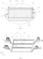
- FIG. 1 is a schematic diagram of a structure of a chassis 100 of a vehicle according to some embodiments of the present application.
- the chassis 100 of a vehicle includes end frames 10 and a battery compartment 20, wherein the end frames 10 are configured for mounting suspensions; and the battery compartment 20 is configured for accommodating a battery.
- the suspension also known as a suspension component, is an assembly of connecting mechanism between a wheel and a vehicle body, typically including a spring, a shock absorber, a swing arm and other accessories.
- the vehicle body is supported on the wheels by means of the suspensions, and the suspensions are configured for controlling the wheel hob to allow the vehicle to drive smoothly.
- the end frames 10 are configured for mounting the suspensions, a driving motor, and other vehicle components.
- the end frames 10 may include a front end frame for mounting two front wheels and suspensions thereof and a rear end frame for mounting two rear wheels and suspensions thereof.
- the battery compartment 20 is configured for accommodating a battery and supplies power to the vehicle.
- a first direction X is a moving direction of the vehicle, including forward and backward directions.
- FIG. 1 is a schematic diagram of a structure of a chassis of a vehicle according to some embodiments of the present application
- FIG. 2 is a schematic diagram of a structure of a first battery module according to some embodiments of the present application
- FIG. 3 is a schematic diagram of a structure of a second battery module according to some embodiments of the present application
- FIG. 4 is a schematic diagram of a structure of the chassis of a vehicle according to some embodiments of the present application in which battery modules are mounted
- FIG. 5 is a partial enlarged view of part A in FIG. 4
- FIG. 6 is a schematic diagram of a structure of the chassis of a vehicle according to some embodiments of the present application in which no battery module is mounted
- FIG. 7 is a partial enlarged view of part B in FIG. 6 .
- a battery compartment 20 is provided.
- the battery compartment 20 includes: a battery compartment frame 200 for accommodating battery modules 40; and at least two battery modules 40 disposed in the battery compartment frame 200; wherein each of the battery modules 40 includes a plurality of battery cells 400 and two end plates, the battery cells 400 are arranged in the first direction X, and the two end plates are respectively disposed on two ends of the plurality of battery cells 400 in the first direction X; the at least two battery modules 40 are arranged in a row in the first direction X; and the at least two battery modules 40 and the battery compartment frame 200 are configured to be in interference-fit in the first direction X.
- the battery modules 40 are mounted in the battery compartment frame 200 in an interference-fit manner, the end plates on two sides of each battery module 40 clamp the battery cells 400 therebetween in the first direction X, and the battery cells 400 are fixed and held in the battery compartment frame 200 in a manner of being clamped in the first direction X, so that the battery cells 400 can be fixed without adhering the battery cells 400 in the battery compartment 20, and it is convenient to remove the battery modules 40 for repair or replacement of the battery cells 40, thereby improving the replacement and repair performance of the battery cells 400 in the battery compartment 20.
- the at least two battery modules 40 and the battery compartment frame 200 being configured in interference-fit in the first direction X specifically means that, when not being stressed, the at least two battery modules 40 arranged in a row have a length in the first direction X slightly greater than the length of the internal space of the battery compartment frame 200, so that when the at least two battery modules 40 are placed in the battery compartment frame 200 in an interference-fit manner, the at least two battery modules 40 are clamped and fixed in the battery compartment frame 200 under the action of the clamping force of the battery compartment frame 200.
- FIG. 2 shows a schematic diagram of a structure of a first battery module 41 according to some embodiments of the present application.
- FIG. 3 shows a schematic diagram of a structure of a second battery module 42 according to some embodiments of the present application.
- the first battery module 41 includes a plurality of battery cells 400, a first end plate 411 and a second end plate 413.
- the second battery module 42 includes a plurality of battery cells 400, a third end plate 421 and a fourth end plate 423.
- the battery cells 400 are prismatic batteries, and the battery cells 400 are arranged such that an expansion direction of the battery cells 400 is parallel to the first direction X. That is, a side surface of the battery cell 400 having the largest area is perpendicular to the first direction X.
- the first direction X is a length direction of the vehicle, but not limited thereto, the first direction X may also be a width direction or a vertical direction of the vehicle.
- a first lifting slot 53 is formed between the two adjacent end plates of the two adjacent battery modules 40; and a second lifting slot 63 is formed between the battery compartment frame 200 and the end plate adjacent to the battery compartment frame 200.
- the first lifting slot 53 is formed between the second end plate 413 and the fourth end plate 423, which are adjacent to each other, of the first battery module 41 and the second battery module 42 adjacent to each other.
- a second lifting slot 63 is formed between the battery compartment frame 200 and the first end plate 411 of the first battery module 41 adjacent to the battery compartment frame 200.
- a second lifting slot 63 is also formed between the battery compartment frame 200 and the third end plate 421 of the second battery module 42 adjacent to the battery compartment frame 200.
- lifting tongs can operate to remove or place a single battery module 40, and during the removal or placement of the battery module 40, operation arms of the lifting tongs extend into the first lifting slot 53 and the second lifting slot 63 and apply pressing force to the battery module 40 in the first direction X so as to change the size of the battery module 40 in the first direction X after being pressed, so that the battery module 40 can be conveniently removed or placed.
- the two adjacent end plates of the two adjacent battery modules 40 are connected by means of a first engagement structure 50.
- the first engagement structure 50 can achieve mutual positioning of the two battery modules 40 and reduce the assembly gap between the two battery modules 40, thereby improving the space utilization of the battery compartment 20.
- the two end plates are connected by means of the first engagement structure 50, and the combined structure of the two end plates can also reinforce the entire battery compartment 20, and can function to replace an intermediate member located between two adjacent battery modules in an existing battery compartment and extending in a third direction Y perpendicular to the first direction X, so that the internal structure of the battery compartment 20 is more compact, and the space utilization is high.
- the engagement structure is generally a recess-protrusion fit structure, including a protrusion provided on one of two mating components and a recess provided on the other component, the protrusion being in shape-fit with the recess to form a connecting and limiting structure.
- the engagement structure includes alternately arranged protrusions and recesses provided on one of two mating components and alternately arranged recesses and protrusions provided on the other component, the protrusions being in shape-fit with the recesses to form the connection and limiting engagement structure.
- the first engagement structure 50 includes a first protrusion 51 provided on one of the two adjacent end plates of the two adjacent battery modules 40 and a first recess 52 provided on the other end plate, the first protrusion 51 being connected to the first recess 52 in an engagement manner.
- the first engagement structure 50 includes the first protrusion 51 and the first recess 52 provided on the two end plates of the two adjacent battery modules 40, and the first protrusion 51 is connected to the first recess 52 in an insertion manner to form the first engagement structure 50, which can achieve mutual limiting of the two battery modules 40 in the third direction Y perpendicular to the first direction X.
- the third direction is a width direction of the vehicle, but not limited thereto, the third direction may also be the length direction or the vertical direction of the vehicle.
- the first engagement structure 50 is disposed between the second end plate 413 of the first battery module 41 and the fourth end plate 423 of the second battery module 42.
- the second end plate 413 is provided with the alternately arranged first protrusions 51 and third recesses 55
- the fourth end plate 423 is provided with the alternately arranged first recesses 52 and third protrusions 54.
- the first recess 52 is connected to the first protrusion 51 in an insertion manner
- the third recess 55 is connected to the third protrusion 54 in an insertion manner, so as to form the first engagement structure 50, which can achieve mutual limiting of the two battery modules 40 in the third direction Y perpendicular to the first direction X.
- the first protrusion 51 protrudes in the first direction X, and the first recess 52 is recessed in the first direction X; the first protrusion 51 and the first recess 52 extend in the second direction Z; and the second direction Z is perpendicular to the first direction X and the third direction Y.
- the first recess 52 is provided with a first insertion opening through which the first protrusion 51 is inserted or removed.
- the first protrusion 51 and the first recess 52 are connected to each other in an insertion manner in the first direction X to form the first engagement structure 50.
- the first protrusion 51 is inserted into the first recess 52 or exits from the first recess 52 through the first insertion opening in the second direction Z so as to achieve connection or separation of the two battery modules 40.
- the structure and fitting relationship of the third recess 55 and the third protrusion 54 are the same as those of the first recess 52 and the first protrusion 51.
- the second direction Z is a vertical direction. But not limited thereto, in some embodiments, the second direction Z may also be the width direction or the length direction of the vehicle.
- the first protrusion 51 is provided with a first lifting slot 53, and the first lifting slot 53 is recessed in the first direction X and extends in the second direction Z; and the first lifting slot 53 is provided with a second insertion opening on at least one end in the second direction Z.
- the first lifting slot 53 is provided on the first protrusion 51, so that the first lifting slot 53 can be arranged by making full use of space of the first protrusion 51, which facilitates operation of the lifting tongs.
- each battery module 40 is provided with a first lifting slot 53 on one or both ends in the first direction X, which is convenient for the lifting tongs to clamp the battery module 40 from two sides.
- the first lifting slot 53 may also be provided on the third protrusion 54.
- the battery compartment frame 200 includes two first side members 21 disposed oppositely in the first direction X; the at least two battery modules 40 include a battery module 40 connected to one of the first side members 21; and one end plate, opposite to one of the first side members 21, of the battery module 40 connected to the first side member 21 is connected to the first side member 21 by means of a second engagement structure 60.
- the second engagement structure 60 is disposed on the first side member 21 and the end plate of the battery module 40 opposite to the first side member 21, which can achieve connection and limiting between the first side member 21 and the battery module 40 adjacent to the first side member 21.
- the battery compartment frame 200 includes two first side members 21 disposed oppositely in the first direction X and two second side members 22 disposed oppositely in the third direction Y.
- the first side members 21 and the second side members 22 are connected to each other to enclose an accommodation space for accommodating the battery modules.
- the battery compartment frame 200 further includes a bottom plate 24, and the bottom plate 24 is connected to the first side members 21 and the second side members 22 from the bottom and closes the battery compartment from the bottom.
- the battery compartment may be square or in other polygonal shapes.
- the second engagement structure 60 includes a second protrusion 61 provided on one of the first side member 21 and the end plate opposite to the first side member 21 and a second recess 62 provided on the other of the first side member 21 and the end plate opposite to the first side member 21, the second protrusion 61 being connected to the second recess 62 in an engagement manner.
- the second engagement structure 60 includes the second protrusion and the second recess respectively arranged on the first side member and the end plate of the battery module opposite to the first side member, and the second protrusion is connected to the second recess in an insertion manner to form the second engagement structure 60, which can achieve mutual limiting of the first side member 21 and the battery module 40 adjacent to the first side member in the third direction Y perpendicular to the first direction X.
- the second engagement structure 60 is disposed between the first end plate 411 of the first battery module 41 and the first side member 21.
- the first end plate 411 is provided with alternately arranged second protrusions 61 and fourth recesses 65
- the first side member 21 is provided with alternately arranged second recesses 62 and fourth protrusions 64.
- the second recess 62 is connected to the second protrusion 61 in an insertion manner, and the fourth recess 65 is connected to the fourth protrusion 64 in an insertion manner, so as to form the second engagement structure 60, which can achieve mutual limiting of the first battery module 41 and the first side member 21 in the third direction Y perpendicular to the first direction X.
- the second protrusion 61 protrudes in the first direction X, and the second recess 62 is recessed in the first direction X; the second protrusion 61 and the second recess 62 extend in the second direction Z; the second direction Z is perpendicular to the first direction X; and on at least one end in the second direction Z, the second recess 62 is provided with a third insertion opening through which the second protrusion 61 is inserted or removed.
- the second protrusion 61 and the second recess 62 are connected to each other in an insertion manner in the first direction X to form the second engagement structure 60.
- the second protrusion 61 When the battery module 40 is mounted or removed, the second protrusion 61 is inserted into the second recess 62 or exits from the second recess 62 through the third insertion opening in the second direction Z, so that the battery module 40 is connected to or separated from the first side member 61.
- the structure and fitting relationship of the fourth recess 65 and the fourth protrusion 64 are the same as those of the second recess 62 and the second protrusion 61.
- the fourth protrusion 64 is provided with a second lifting slot 63, and the second lifting slot 63 is recessed in the first direction X and extends in the second direction Z; and the second lifting slot 63 is provided with a fourth insertion opening on at least one end in the second direction Z.
- the second lifting slot 63 is provided on the fourth protrusion 64, so that the second lifting slot 63 can be arranged by making full use of space of the fourth protrusion 64, which facilitates operation of the lifting tongs.
- the second lifting slot 63 may also be provided on the second protrusion 61.
- multiple rows of the battery modules 40 are provided in the battery compartment frame 200; the multiple rows of the battery modules 40 are arranged in the third direction Y, and the third direction Y is perpendicular to the first direction X; and an intermediate member 23 is provided between the two adjacent rows of the battery modules 40, and two ends of the intermediate member 23 are respectively connected to the first side members 21.
- the intermediate member 23 By means of providing the intermediate member 23, the position of each row of the battery modules 40 in the third direction Y can be limited, and the intermediate member 23 can also reinforce the battery compartment frame 200.
- a chassis 100 is provided.
- the chassis 100 includes the battery compartment frame 200 in the above embodiments, and end frames 10 for mounting suspensions.
- the end frames 10 are connected to end portions of the battery compartment frame 200 of the battery compartment 20 in the first direction X.
- the battery compartment 20 is directly connected to the end frames 10, so that cross members, longitudinal members and other structures at a cab part of a conventional chassis are omitted, greatly reducing the number of components of the vehicle, which improves the space utilization of the chassis 100 and is conducive to carrying more batteries in the battery compartment 20, thereby further improving the endurance of the vehicle.
- the end frames 10 include a front end frame and a rear end frame.
- the front end frame is mounted at the front of the battery compartment 20, and the rear end frame is mounted at the rear of the battery compartment 20.
- each end frame 10 includes two frame longitudinal members 11 and two shock absorber towers 12, wherein each of the frame longitudinal members 11 is provided with one shock absorber tower 12; a set of suspensions are mounted on each of the frame longitudinal members 11 and the corresponding shock absorber tower 12; and the two frame longitudinal members 11 are connected to the battery compartment frame 200.
- the end frame 10 includes two frame longitudinal members 11 and two shock absorber towers 12, and a set of suspensions are mounted on each frame longitudinal member 11 and the corresponding shock absorber tower 12.
- the suspensions are directly mounted on the frame longitudinal members 11 and the shock absorber towers 12, which can omit a subframe and other suspension mounting structures of the vehicle, greatly reducing the number of components of the end frames to achieve higher integration level.
- the two frame longitudinal members 11 are mounted at the end portions of the battery compartment 20, and the end frames 10 are directly carried by the battery compartment, which omits the cross members, longitudinal member and other structures of the vehicle, so that the entire chassis has a compact structure and less components and is lightweight.
- the frame longitudinal member 11 is further provided with a motor mounting base 13.
- a driving motor can be mounted on the frame longitudinal members 11 and supported by the frame longitudinal members 11, which further improves the compactness of the chassis 100 and reduces the number of components.
- a vehicle in a third aspect of the present application, includes the chassis of a vehicle in the above embodiments.
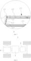
- FIG. 8 is a simplified schematic diagram of a vehicle according to some embodiments of the present application.
- a battery 2 is disposed inside the vehicle 1, and the battery 2 may be disposed in a battery compartment 20 of the vehicle 1.
- the battery 2 may be configured to supply power to the vehicle 1, for example, the battery 2 may serve as a power supply for operating the vehicle 1.
- the vehicle 1 may further include a controller 3 and a motor 4.
- the controller 3 is configured for controlling the battery 2 to supply power to the motor 4, for example, to meet working power requirements during starting, navigation and traveling of the vehicle 1.
- the battery 2 can not only serve as a power supply for operating the vehicle 1, but can also serve as a power supply for driving the vehicle 1, in place of or partially in place of fuel or natural gas, to provide driving power for the vehicle 1.
Landscapes
- Engineering & Computer Science (AREA)
- Chemical & Material Sciences (AREA)
- Chemical Kinetics & Catalysis (AREA)
- General Chemical & Material Sciences (AREA)
- Electrochemistry (AREA)
- Transportation (AREA)
- Mechanical Engineering (AREA)
- Combustion & Propulsion (AREA)
- Aviation & Aerospace Engineering (AREA)
- Life Sciences & Earth Sciences (AREA)
- Sustainable Development (AREA)
- Sustainable Energy (AREA)
- Power Engineering (AREA)
- Battery Mounting, Suspending (AREA)
Abstract
Description
- The present application claims the priority of
Chinese patent application no. 202111302274.2, entitled "BATTERY COMPARTMENT, CHASSIS, AND VEHICLE" and filed on November 4, 2021 - The present application relates to the field of vehicles, and in particular to a battery compartment, a chassis and a vehicle.
- In an existing electric vehicle, battery cells in a battery compartment are typically fixed in the battery compartment using an adhesive, so that it will be difficult to repair and replace the battery cells when they fail. Therefore, how to improve the replacement and repair performance of the battery cells in the battery compartment is a technical problem to be solved urgently for the electric vehicle.
- In various aspects of the present application, a battery compartment, a chassis and a vehicle are provided, which can improve the replacement and repair performance of the battery compartment of an electric vehicle.
- In a first aspect of the present application, a battery compartment is provided. The battery compartment includes: a battery compartment frame for accommodating battery modules; and at least two battery modules disposed in the battery compartment frame; wherein each of the battery modules includes a plurality of battery cells and two end plates, the plurality of battery cells are arranged in a first direction, and the two end plates are respectively disposed on two ends of the plurality of battery cells in the first direction; the at least two battery modules are arranged in a row in the first direction; and the at least two battery modules and the battery compartment frame are configured to be in interference-fit in the first direction.
- In this embodiment, by means of allowing the at least two battery modules and the battery compartment frame to be configured in interference-fit in the first direction, the battery cells are fixed in the battery compartment frame in a clamped manner in the first direction, so that the battery cells are fixed without using an adhesive, and it is also convenient to remove the battery modules for repair and replacement of the battery cells, thereby improving the replacement and repair performance of the battery cells in the battery compartment.
- In some embodiments, a first lifting slot is formed between the two adjacent end plates of the two adjacent battery modules; and a second lifting slot is formed between the battery compartment frame and the end plate adjacent to the battery compartment frame. By means of providing the first lifting slot and the second lifting slot, lifting tongs can operate to remove or place a single battery module, and during the removal or placement of the battery module, operation arms of the lifting tongs extend into the first lifting slot and the second lifting slot and apply pressing force to the battery module in the first direction so as to change the size of the battery module in the first direction after being pressed, so that the battery module can be conveniently removed or placed.
- In some embodiments, the two adjacent end plates of the two adjacent battery modules are connected by means of a first engagement structure. The first engagement structure can achieve mutual positioning of the two battery modules and reduce the assembly gap between the two battery modules, thereby improving the space utilization of the battery compartment. Also, the two end plates are connected by means of the first engagement structure, and the combined structure of the two end plates can also reinforce the entire battery compartment, and can function to replace an intermediate member located between two adjacent battery modules in an existing battery compartment and arranged in a third direction perpendicular to the first direction, so that the internal structure of the battery compartment is more compact, and the space utilization is high.
- In some embodiments, the first engagement structure includes a first protrusion provided on one of the two adjacent end plates of the two adjacent battery modules and a first recess provided on the other end plate, the first protrusion being connected to the first recess in an engagement manner. The first engagement structure includes the first protrusion and the first recess respectively provided on the two end plates of the two adjacent battery modules, and the first protrusion is connected to the first recess in an insertion manner to form the first engagement structure, which can achieve mutual limiting of the two battery modules in the third direction perpendicular to the first direction.
- In some embodiments, the first protrusion protrudes in the first direction, and the first recess is recessed in the first direction; the first protrusion and the first recess extend in a second direction; the second direction is perpendicular to the first direction; and on at least one end in the second direction, the first recess is provided with a first insertion opening through which the first protrusion is inserted or removed. The first protrusion and the first recess are connected to each other in an insertion manner in the first direction to form the first engagement structure. When the battery module is mounted or removed, the first protrusion is inserted into or exits from the first recess through the first insertion opening in the second direction so as to achieve connection or separation of the two battery modules.
- In some embodiments, the first protrusion is provided with a first lifting slot recessed in the first direction and extending in the second direction; and the first lifting slot is provided with a second insertion opening on at least one end in the second direction. The first lifting slot is provided on the first protrusion, so that the first lifting slot can be arranged by making full use of space of the first protrusion, which facilitates operation of the lifting tongs.
- In some embodiments, the battery compartment frame includes two first side members disposed oppositely in the first direction; the at least two battery modules include a battery module connected to one of the first side members; and one end plate, opposite to one of the first side members, of the battery module connected to the first side member is connected to the first side member by means of a second engagement structure. The second engagement structure is disposed on the first side member and one end plate of the battery module opposite to the first side member, which can achieve connection and limiting of the first side member and the battery module adjacent to the first side member.
- In some embodiments, the second engagement structure includes a second protrusion provided on one of the first side member and the end plate opposite to the first side member and a second recess provided on the other of the first side member and the end plate opposite to the first side member, the second protrusion being connected to the second recess in an engagement manner. The second engagement structure includes the second protrusion and the second recess respectively provided on the first side member and the end plate of the battery module opposite to the first side member, and the second protrusion is connected to the second recess in an insertion manner to form the second engagement structure, which can achieve mutual limiting of the first side member and the battery module adjacent to the first side member in the third direction perpendicular to the first direction.
- In some embodiments, the second protrusion protrudes in the first direction, and the second recess is recessed in the first direction; the second protrusion and the second recess extend in the second direction; the second direction is perpendicular to the first direction; and on at least one end in the second direction, the second recess is provided with a third insertion opening through which the second protrusion is inserted or removed. The second protrusion and the second recess are connected to each other in an insertion manner in the first direction to form the second engagement structure. When the battery module is mounted or removed, the second protrusion is inserted into or exits from the second recess through the third insertion opening in the second direction, so that the battery module is connected to or separated from the first side member.
- In some embodiments, the second protrusion is provided with a second lifting slot recessed in the first direction and extending in the second direction; and the second lifting slot is provided with a fourth insertion opening on at least one end in the second direction. The second lifting slot is provided on the second protrusion, so that the second lifting slot can be arranged by making full use of space of the second protrusion, which facilitates operation of the lifting tongs.
- In some embodiments, multiple rows of the battery modules are provided in the battery compartment frame; the multiple rows of the battery modules are arranged in the third direction perpendicular to the first direction; and an intermediate member is provided between the two adjacent rows of the battery modules, and two ends of the intermediate member are respectively connected to the first side members. By means of providing the intermediate member, the position of each row of the battery modules in the third direction can be limited, and the intermediate member can also reinforce the battery compartment frame.
- In a second aspect of the present application, a chassis is provided. The chassis includes the battery compartment frame in the above embodiments, and end frames for mounting suspensions. The end frames are connected to end portions of the battery compartment frame of the battery compartment in the first direction. The battery compartment is directly connected to the end frames, so that cross members, longitudinal members and other structures at a cab part of a conventional chassis are omitted, greatly reducing the number of components of the vehicle, which improves the space utilization of the chassis and is conducive to carrying more batteries in the battery compartment, thereby further improving the endurance of the vehicle.
- In some embodiments, the end frames include a front end frame and a rear end frame.
- In some embodiments, the end frame includes two frame longitudinal members, two shock absorber towers and a first cross member, wherein each of the frame longitudinal members is provided with one shock absorber tower; a set of suspensions are mounted on each of the frame longitudinal members and the corresponding shock absorber tower; and the two frame longitudinal members are connected to the battery compartment frame. In this embodiment, the end frame includes two frame longitudinal members and two shock absorber towers, a set of suspensions are mounted on each frame longitudinal member and the corresponding shock absorber tower. The suspensions are directly mounted on the frame longitudinal members and the shock absorber towers, so that a subframe and other suspension mounting structures of the vehicle can be omitted, greatly reducing the number of components of the end frames to achieve higher integration level. The two frame longitudinal members are mounted at the end portions of the battery compartment, and the end frames are directly carried by the battery compartment, which omits the cross members, longitudinal member and other structures of the vehicle body, so that the entire chassis has a compact structure and less components and is lightweight.
- In some embodiments, the frame longitudinal member is further provided with a motor mounting base. By means of providing the motor mounting base, a driving motor can be mounted on and supported by the frame longitudinal members, which further improves the compactness of the chassis and reduces the number of components.
- In a third aspect of the present application, a vehicle is provided. The vehicle includes the chassis of a vehicle in the above embodiments.
- The aforementioned description is merely an overview of the technical solutions of the embodiments of the present application. In order to more clearly understand the technical means of the embodiments of the present application to implement the technical means according to the content of the specification, and in order to make the above and other objectives, features and advantages of the embodiments of the present application more obvious and understandable, specific implementations of the present application are illustratively described below.
- In order to more clearly illustrate the technical solutions in the embodiments of the present application, the drawings to be used in the description of the embodiments will be described briefly below. Obviously, the drawings in the following description are merely some embodiments of the present application. For those of ordinary skill in the art, other drawings can also be obtained according to these drawings without involving any inventive effort.
-
FIG. 1 is a schematic diagram of a structure of a chassis of a vehicle according to some embodiments of the present application; -
FIG. 2 is a schematic diagram of a structure of a first battery module according to some embodiments of the present application; -
FIG. 3 is a schematic diagram of a structure of a second battery module according to some embodiments of the present application; -
FIG. 4 is a schematic diagram of a structure of the chassis of a vehicle according to some embodiments of the present application in which battery modules are mounted; -
FIG. 5 is a partial enlarged view of part A inFIG. 4 ; -
FIG. 6 is a schematic diagram of a structure of the chassis of a vehicle according to some embodiments of the present application in which no battery module is mounted; -
FIG. 7 is a partial enlarged view of part B inFIG. 6 ; and -
FIG. 8 is a simplified schematic diagram of a vehicle according to some embodiments of the present application. - In order to make the objectives, technical solutions and advantages of embodiments of the present application clearer, the technical solutions in the embodiments of the present application will be described clearly and completely below with reference to the accompanying drawings in the embodiments of the present application. Apparently, the embodiments described are some, but not all, embodiments of the present application. All other embodiments obtained by those of ordinary skill in the art on the basis of the embodiments of the present application without involving any inventive effort shall fall within the scope of protection of the present application.
- Unless otherwise defined, all technical and scientific terms used herein have the same meanings as those commonly understood by those skilled in the art to which the present application belongs. The terms used in the description of the present application herein are merely for the purpose of describing the specific embodiments, but are not intended to limit the present application. The terms "including" and "having" and any variations thereof in the specification and the claims of the present application as well as the brief description of the accompanying drawings described above are intended to cover non-exclusive inclusion.
- The phrase "embodiment" mentioned herein means that the specific features, structures, or characteristics described in conjunction with the embodiment can be encompassed in at least one embodiment of the present application. The phrase at various locations in the specification does not necessarily refer to the same embodiment, or an independent or alternative embodiment exclusive of another embodiment. Those skilled in the art understand explicitly or implicitly that the embodiment described herein may be combined with another embodiment.
- The term "and/or" herein is merely the description of an associated relationship of associated objects, and indicates that three relationships may exist. For example, A and/or B may indicate: only A exists, both A and B exist, and only B exists. In addition, the character "/" herein generally indicates an "or" relationship between the associated objects.
- In the description of the present application, it should be understood that the orientation or positional relationships indicated by the terms "center", "longitudinal", "transverse", "length", "width", "thickness", "upper", "lower", "front", "rear", "left", "right", "vertical", "horizontal", "top", "bottom", "inner", "outer", "clockwise", "anticlockwise", "axial", "radial", "circumferential", etc. are based on the orientation or positional relationships shown in the accompanying drawings and are merely for ease of description of the present application and simplification of the description, rather than indicating or implying that the devices or elements referred to must have a specific orientation or be constructed and operated in a described orientation, and therefore cannot be construed as limiting the present application. In addition, the terms "first", "second", etc. in the specification, the claims, or the accompanying drawings of the present application are used for distinguishing different objects, instead of describing a specific order, and thus can explicitly or implicitly include one or more features. In the description of the present application, the term "a plurality of' means two or more, unless otherwise specified.
- In the description of the present application, it should be noted that the terms "mounting", "connecting", and "connection" should be interpreted in the broad sense unless explicitly defined and limited otherwise. For example, the connection may be a fixed connection, a detachable connection, or an integral connection; or may be a mechanical connection or an electrical connection; or may be a direct connection, an indirect connection by means of an intermediate medium, or internal communication between two elements. For those of ordinary skill in the art, the specific meanings of the terms in the present application can be construed according to specific circumstances.
- In the present application, the battery cell may include a lithium-ion secondary battery cell, a lithium-ion primary battery cell, a lithium-sulfur battery cell, a sodium-lithium-ion battery cell, a sodium-ion battery cell, a magnesium-ion battery cell, etc., which will not be limited in the embodiments of the present application. The battery cell may be cylindrical, flat, cuboid or in other shapes, which will also not be limited in the embodiments of the present application. The battery cells are generally classified into three types depending on the way of package: cylindrical battery cells, prismatic battery cells and pouch battery cells, which will also not be limited in the embodiments of the present application.
- The battery mentioned in the embodiments of the present application refers to a single physical module including one or more battery cells to provide a higher voltage and capacity. For example, the battery mentioned in the present application may include a battery module, a battery pack, etc. The battery generally includes a case for packaging one or more battery cells. The case can prevent liquid or other foreign matters from affecting charging or discharging of the battery cells.
- The technical solutions described in the embodiments of the present application are applicable to a vehicle, which may be a fuel vehicle, a gas vehicle or a new-energy vehicle. The new-energy vehicle may be a battery electric vehicle, a hybrid vehicle, an extended-range vehicle, etc. The vehicle mentioned above is not specially limited in the embodiments of the present application.
- In an existing vehicle, battery cells in a battery compartment are typically fixed in the battery compartment using an adhesive, so that if a battery cell fails later, it is difficult to repair and replace the battery cell, and the operation is inconvenient.
- In order to solve the above technical problem, the inventors of the present application propose a chassis structure and a battery compartment structure of a vehicle.
FIG. 1 is a schematic diagram of a structure of achassis 100 of a vehicle according to some embodiments of the present application. - As shown in
FIG. 1 , thechassis 100 of a vehicle includes end frames 10 and abattery compartment 20, wherein the end frames 10 are configured for mounting suspensions; and thebattery compartment 20 is configured for accommodating a battery. - In some embodiments, the suspension, also known as a suspension component, is an assembly of connecting mechanism between a wheel and a vehicle body, typically including a spring, a shock absorber, a swing arm and other accessories. The vehicle body is supported on the wheels by means of the suspensions, and the suspensions are configured for controlling the wheel hob to allow the vehicle to drive smoothly.
- In some embodiments, the end frames 10 are configured for mounting the suspensions, a driving motor, and other vehicle components. For a four-wheeled vehicle, the end frames 10 may include a front end frame for mounting two front wheels and suspensions thereof and a rear end frame for mounting two rear wheels and suspensions thereof.
- In some embodiments, the
battery compartment 20 is configured for accommodating a battery and supplies power to the vehicle. - In some embodiments, a first direction X is a moving direction of the vehicle, including forward and backward directions.
-
FIG. 1 is a schematic diagram of a structure of a chassis of a vehicle according to some embodiments of the present application;FIG. 2 is a schematic diagram of a structure of a first battery module according to some embodiments of the present application;FIG. 3 is a schematic diagram of a structure of a second battery module according to some embodiments of the present application;FIG. 4 is a schematic diagram of a structure of the chassis of a vehicle according to some embodiments of the present application in which battery modules are mounted;FIG. 5 is a partial enlarged view of part A inFIG. 4 ;FIG. 6 is a schematic diagram of a structure of the chassis of a vehicle according to some embodiments of the present application in which no battery module is mounted;FIG. 7 is a partial enlarged view of part B inFIG. 6 . - In a first aspect of the embodiments of the present application, a
battery compartment 20 is provided. As shown in the embodiments inFIGS. 1 to 7 , thebattery compartment 20 includes: abattery compartment frame 200 for accommodatingbattery modules 40; and at least twobattery modules 40 disposed in thebattery compartment frame 200; wherein each of thebattery modules 40 includes a plurality ofbattery cells 400 and two end plates, thebattery cells 400 are arranged in the first direction X, and the two end plates are respectively disposed on two ends of the plurality ofbattery cells 400 in the first direction X; the at least twobattery modules 40 are arranged in a row in the first direction X; and the at least twobattery modules 40 and thebattery compartment frame 200 are configured to be in interference-fit in the first direction X. In this embodiment, by means of allowing the at least twobattery modules 40 and thebattery compartment frame 200 to be configured in interference-fit in the first direction X, thebattery modules 40 are mounted in thebattery compartment frame 200 in an interference-fit manner, the end plates on two sides of eachbattery module 40 clamp thebattery cells 400 therebetween in the first direction X, and thebattery cells 400 are fixed and held in thebattery compartment frame 200 in a manner of being clamped in the first direction X, so that thebattery cells 400 can be fixed without adhering thebattery cells 400 in thebattery compartment 20, and it is convenient to remove thebattery modules 40 for repair or replacement of thebattery cells 40, thereby improving the replacement and repair performance of thebattery cells 400 in thebattery compartment 20. - In some embodiments, there may be two, three, or
more battery modules 40 arranged in a row in the first direction X. There may be one ormore battery cells 400 in eachbattery module 40. - The at least two
battery modules 40 and thebattery compartment frame 200 being configured in interference-fit in the first direction X specifically means that, when not being stressed, the at least twobattery modules 40 arranged in a row have a length in the first direction X slightly greater than the length of the internal space of thebattery compartment frame 200, so that when the at least twobattery modules 40 are placed in thebattery compartment frame 200 in an interference-fit manner, the at least twobattery modules 40 are clamped and fixed in thebattery compartment frame 200 under the action of the clamping force of thebattery compartment frame 200. -
FIG. 2 shows a schematic diagram of a structure of afirst battery module 41 according to some embodiments of the present application.FIG. 3 shows a schematic diagram of a structure of asecond battery module 42 according to some embodiments of the present application. InFIG. 1 , there may be twobattery modules 40 arranged in a row in the first direction X, including thefirst battery module 41 and thesecond battery module 42. Thefirst battery module 41 includes a plurality ofbattery cells 400, afirst end plate 411 and asecond end plate 413. Thesecond battery module 42 includes a plurality ofbattery cells 400, athird end plate 421 and afourth end plate 423. - The
battery cells 400 are prismatic batteries, and thebattery cells 400 are arranged such that an expansion direction of thebattery cells 400 is parallel to the first direction X. That is, a side surface of thebattery cell 400 having the largest area is perpendicular to the first direction X. The first direction X is a length direction of the vehicle, but not limited thereto, the first direction X may also be a width direction or a vertical direction of the vehicle. - In some embodiments, a
first lifting slot 53 is formed between the two adjacent end plates of the twoadjacent battery modules 40; and asecond lifting slot 63 is formed between thebattery compartment frame 200 and the end plate adjacent to thebattery compartment frame 200. - Specifically, taking the embodiments shown in
FIGS. 2 to 5 as an example, thefirst lifting slot 53 is formed between thesecond end plate 413 and thefourth end plate 423, which are adjacent to each other, of thefirst battery module 41 and thesecond battery module 42 adjacent to each other. Asecond lifting slot 63 is formed between thebattery compartment frame 200 and thefirst end plate 411 of thefirst battery module 41 adjacent to thebattery compartment frame 200. Asecond lifting slot 63 is also formed between thebattery compartment frame 200 and thethird end plate 421 of thesecond battery module 42 adjacent to thebattery compartment frame 200. - In this embodiment, by means of providing the
first lifting slot 53 and thesecond lifting slot 63, lifting tongs can operate to remove or place asingle battery module 40, and during the removal or placement of thebattery module 40, operation arms of the lifting tongs extend into thefirst lifting slot 53 and thesecond lifting slot 63 and apply pressing force to thebattery module 40 in the first direction X so as to change the size of thebattery module 40 in the first direction X after being pressed, so that thebattery module 40 can be conveniently removed or placed. - In some embodiments, the two adjacent end plates of the two
adjacent battery modules 40 are connected by means of afirst engagement structure 50. Thefirst engagement structure 50 can achieve mutual positioning of the twobattery modules 40 and reduce the assembly gap between the twobattery modules 40, thereby improving the space utilization of thebattery compartment 20. Also, the two end plates are connected by means of thefirst engagement structure 50, and the combined structure of the two end plates can also reinforce theentire battery compartment 20, and can function to replace an intermediate member located between two adjacent battery modules in an existing battery compartment and extending in a third direction Y perpendicular to the first direction X, so that the internal structure of thebattery compartment 20 is more compact, and the space utilization is high. - In some embodiments, the engagement structure is generally a recess-protrusion fit structure, including a protrusion provided on one of two mating components and a recess provided on the other component, the protrusion being in shape-fit with the recess to form a connecting and limiting structure. In some embodiments, the engagement structure includes alternately arranged protrusions and recesses provided on one of two mating components and alternately arranged recesses and protrusions provided on the other component, the protrusions being in shape-fit with the recesses to form the connection and limiting engagement structure.
- In some embodiments, the
first engagement structure 50 includes afirst protrusion 51 provided on one of the two adjacent end plates of the twoadjacent battery modules 40 and afirst recess 52 provided on the other end plate, thefirst protrusion 51 being connected to thefirst recess 52 in an engagement manner. Thefirst engagement structure 50 includes thefirst protrusion 51 and thefirst recess 52 provided on the two end plates of the twoadjacent battery modules 40, and thefirst protrusion 51 is connected to thefirst recess 52 in an insertion manner to form thefirst engagement structure 50, which can achieve mutual limiting of the twobattery modules 40 in the third direction Y perpendicular to the first direction X. In some embodiments, the third direction is a width direction of the vehicle, but not limited thereto, the third direction may also be the length direction or the vertical direction of the vehicle. - Specifically, in the embodiments as shown in
FIGS. 2 to 5 , thefirst engagement structure 50 is disposed between thesecond end plate 413 of thefirst battery module 41 and thefourth end plate 423 of thesecond battery module 42. Thesecond end plate 413 is provided with the alternately arrangedfirst protrusions 51 andthird recesses 55, and thefourth end plate 423 is provided with the alternately arranged first recesses 52 andthird protrusions 54. Between thesecond end plate 413 and thefourth end plate 423, thefirst recess 52 is connected to thefirst protrusion 51 in an insertion manner, and thethird recess 55 is connected to thethird protrusion 54 in an insertion manner, so as to form thefirst engagement structure 50, which can achieve mutual limiting of the twobattery modules 40 in the third direction Y perpendicular to the first direction X. - In some embodiments, the
first protrusion 51 protrudes in the first direction X, and thefirst recess 52 is recessed in the first direction X; thefirst protrusion 51 and thefirst recess 52 extend in the second direction Z; and the second direction Z is perpendicular to the first direction X and the third direction Y. On at least one end in the second direction Z, thefirst recess 52 is provided with a first insertion opening through which thefirst protrusion 51 is inserted or removed. Thefirst protrusion 51 and thefirst recess 52 are connected to each other in an insertion manner in the first direction X to form thefirst engagement structure 50. When thebattery module 40 is mounted or removed, thefirst protrusion 51 is inserted into thefirst recess 52 or exits from thefirst recess 52 through the first insertion opening in the second direction Z so as to achieve connection or separation of the twobattery modules 40. The structure and fitting relationship of thethird recess 55 and thethird protrusion 54 are the same as those of thefirst recess 52 and thefirst protrusion 51. - In some embodiments, the second direction Z is a vertical direction. But not limited thereto, in some embodiments, the second direction Z may also be the width direction or the length direction of the vehicle.
- In some embodiments, as shown in
FIGS. 2 to 5 , thefirst protrusion 51 is provided with afirst lifting slot 53, and thefirst lifting slot 53 is recessed in the first direction X and extends in the second direction Z; and thefirst lifting slot 53 is provided with a second insertion opening on at least one end in the second direction Z. Thefirst lifting slot 53 is provided on thefirst protrusion 51, so that thefirst lifting slot 53 can be arranged by making full use of space of thefirst protrusion 51, which facilitates operation of the lifting tongs. As shown in the figures, eachbattery module 40 is provided with afirst lifting slot 53 on one or both ends in the first direction X, which is convenient for the lifting tongs to clamp thebattery module 40 from two sides. In other embodiments, thefirst lifting slot 53 may also be provided on thethird protrusion 54. - In some embodiments, referring to
FIGS. 3 to 6 , thebattery compartment frame 200 includes twofirst side members 21 disposed oppositely in the first direction X; the at least twobattery modules 40 include abattery module 40 connected to one of thefirst side members 21; and one end plate, opposite to one of thefirst side members 21, of thebattery module 40 connected to thefirst side member 21 is connected to thefirst side member 21 by means of asecond engagement structure 60. Thesecond engagement structure 60 is disposed on thefirst side member 21 and the end plate of thebattery module 40 opposite to thefirst side member 21, which can achieve connection and limiting between thefirst side member 21 and thebattery module 40 adjacent to thefirst side member 21. - Specifically, in the embodiments as shown in
FIGS. 4 to 7 , thebattery compartment frame 200 includes twofirst side members 21 disposed oppositely in the first direction X and twosecond side members 22 disposed oppositely in the third direction Y. Thefirst side members 21 and thesecond side members 22 are connected to each other to enclose an accommodation space for accommodating the battery modules. In some embodiments, thebattery compartment frame 200 further includes a bottom plate 24, and the bottom plate 24 is connected to thefirst side members 21 and thesecond side members 22 from the bottom and closes the battery compartment from the bottom. The battery compartment may be square or in other polygonal shapes. - In some embodiments, the
second engagement structure 60 includes asecond protrusion 61 provided on one of thefirst side member 21 and the end plate opposite to thefirst side member 21 and asecond recess 62 provided on the other of thefirst side member 21 and the end plate opposite to thefirst side member 21, thesecond protrusion 61 being connected to thesecond recess 62 in an engagement manner. Thesecond engagement structure 60 includes the second protrusion and the second recess respectively arranged on the first side member and the end plate of the battery module opposite to the first side member, and the second protrusion is connected to the second recess in an insertion manner to form thesecond engagement structure 60, which can achieve mutual limiting of thefirst side member 21 and thebattery module 40 adjacent to the first side member in the third direction Y perpendicular to the first direction X. - Specifically, in the embodiments as shown in
FIGS. 4 to 7 , thesecond engagement structure 60 is disposed between thefirst end plate 411 of thefirst battery module 41 and thefirst side member 21. Thefirst end plate 411 is provided with alternately arrangedsecond protrusions 61 andfourth recesses 65, and thefirst side member 21 is provided with alternately arranged second recesses 62 andfourth protrusions 64. Between thefirst end plate 411 and thefirst side member 21, thesecond recess 62 is connected to thesecond protrusion 61 in an insertion manner, and thefourth recess 65 is connected to thefourth protrusion 64 in an insertion manner, so as to form thesecond engagement structure 60, which can achieve mutual limiting of thefirst battery module 41 and thefirst side member 21 in the third direction Y perpendicular to the first direction X. - In some embodiments, the
second protrusion 61 protrudes in the first direction X, and thesecond recess 62 is recessed in the first direction X; thesecond protrusion 61 and thesecond recess 62 extend in the second direction Z; the second direction Z is perpendicular to the first direction X; and on at least one end in the second direction Z, thesecond recess 62 is provided with a third insertion opening through which thesecond protrusion 61 is inserted or removed. Thesecond protrusion 61 and thesecond recess 62 are connected to each other in an insertion manner in the first direction X to form thesecond engagement structure 60. When thebattery module 40 is mounted or removed, thesecond protrusion 61 is inserted into thesecond recess 62 or exits from thesecond recess 62 through the third insertion opening in the second direction Z, so that thebattery module 40 is connected to or separated from thefirst side member 61. The structure and fitting relationship of thefourth recess 65 and thefourth protrusion 64 are the same as those of thesecond recess 62 and thesecond protrusion 61. - In some embodiments, as shown in
FIG. 6 , thefourth protrusion 64 is provided with asecond lifting slot 63, and thesecond lifting slot 63 is recessed in the first direction X and extends in the second direction Z; and thesecond lifting slot 63 is provided with a fourth insertion opening on at least one end in the second direction Z. Thesecond lifting slot 63 is provided on thefourth protrusion 64, so that thesecond lifting slot 63 can be arranged by making full use of space of thefourth protrusion 64, which facilitates operation of the lifting tongs. In other embodiments, thesecond lifting slot 63 may also be provided on thesecond protrusion 61. - In some embodiments, multiple rows of the
battery modules 40 are provided in thebattery compartment frame 200; the multiple rows of thebattery modules 40 are arranged in the third direction Y, and the third direction Y is perpendicular to the first direction X; and anintermediate member 23 is provided between the two adjacent rows of thebattery modules 40, and two ends of theintermediate member 23 are respectively connected to thefirst side members 21. By means of providing theintermediate member 23, the position of each row of thebattery modules 40 in the third direction Y can be limited, and theintermediate member 23 can also reinforce thebattery compartment frame 200. - Referring to the embodiments as shown in
FIGS. 1 to 7 , in a second aspect of the present application, achassis 100 is provided. Thechassis 100 includes thebattery compartment frame 200 in the above embodiments, and endframes 10 for mounting suspensions. The end frames 10 are connected to end portions of thebattery compartment frame 200 of thebattery compartment 20 in the first direction X. Thebattery compartment 20 is directly connected to the end frames 10, so that cross members, longitudinal members and other structures at a cab part of a conventional chassis are omitted, greatly reducing the number of components of the vehicle, which improves the space utilization of thechassis 100 and is conducive to carrying more batteries in thebattery compartment 20, thereby further improving the endurance of the vehicle. - In some embodiments, the end frames 10 include a front end frame and a rear end frame. The front end frame is mounted at the front of the
battery compartment 20, and the rear end frame is mounted at the rear of thebattery compartment 20. - In some embodiments, each
end frame 10 includes two framelongitudinal members 11 and two shock absorber towers 12, wherein each of the framelongitudinal members 11 is provided with oneshock absorber tower 12; a set of suspensions are mounted on each of the framelongitudinal members 11 and the correspondingshock absorber tower 12; and the two framelongitudinal members 11 are connected to thebattery compartment frame 200. In this embodiment, theend frame 10 includes two framelongitudinal members 11 and two shock absorber towers 12, and a set of suspensions are mounted on each framelongitudinal member 11 and the correspondingshock absorber tower 12. The suspensions are directly mounted on the framelongitudinal members 11 and the shock absorber towers 12, which can omit a subframe and other suspension mounting structures of the vehicle, greatly reducing the number of components of the end frames to achieve higher integration level. The two framelongitudinal members 11 are mounted at the end portions of thebattery compartment 20, and the end frames 10 are directly carried by the battery compartment, which omits the cross members, longitudinal member and other structures of the vehicle, so that the entire chassis has a compact structure and less components and is lightweight. - In some embodiments, the frame
longitudinal member 11 is further provided with amotor mounting base 13. By means of providing themotor mounting base 13, a driving motor can be mounted on the framelongitudinal members 11 and supported by the framelongitudinal members 11, which further improves the compactness of thechassis 100 and reduces the number of components. - In a third aspect of the present application, a vehicle is provided. The vehicle includes the chassis of a vehicle in the above embodiments.
-
FIG. 8 is a simplified schematic diagram of a vehicle according to some embodiments of the present application. - As shown in
FIG. 8 , abattery 2 is disposed inside thevehicle 1, and thebattery 2 may be disposed in abattery compartment 20 of thevehicle 1. Thebattery 2 may be configured to supply power to thevehicle 1, for example, thebattery 2 may serve as a power supply for operating thevehicle 1. - The
vehicle 1 may further include acontroller 3 and amotor 4. Thecontroller 3 is configured for controlling thebattery 2 to supply power to themotor 4, for example, to meet working power requirements during starting, navigation and traveling of thevehicle 1. - In some embodiments of the present application, the
battery 2 can not only serve as a power supply for operating thevehicle 1, but can also serve as a power supply for driving thevehicle 1, in place of or partially in place of fuel or natural gas, to provide driving power for thevehicle 1. - Those skilled in the art should understand that, although some of the embodiments herein include some features, but not other features, included in other embodiments, the combination of the features of different embodiments means being within the scope of the present application and forms different embodiments. For example, in the claims, any one of the claimed embodiments may be used in any combination.
- The foregoing embodiments are merely used for illustrating rather than limiting the technical solutions of the present application. Although the present application has been illustrated in detail with reference to the foregoing embodiments, it should be understood by those of ordinary skill in the art that the technical solutions recited in the foregoing examples may still be modified, or some of the technical features thereof may be equivalently substituted; and the modifications or substitutions do not make the essence of the corresponding technical solutions depart from the spirit and scope of the technical solutions of the embodiments of the present application.
Claims (16)
- A battery compartment, comprising:a battery compartment frame for accommodating battery modules; andat least two battery modules disposed in the battery compartment frame;wherein each of the battery modules comprises a plurality of battery cells and two end plates, the plurality of battery cells being arranged in a first direction, and the two end plates being respectively disposed on two ends of the plurality of battery cells in the first direction;the at least two battery modules are arranged in a row in the first direction; andthe at least two battery modules and the battery compartment frame are configured in interference-fit in the first direction.
- The battery compartment of claim 1, wherein a first lifting slot is formed between the two adjacent end plates of the two adjacent battery modules; and a second lifting slot is formed between the battery compartment frame and the end plate adjacent to the battery compartment frame.
- The battery compartment of claim 1 or 2, wherein the two adjacent end plates of the two adjacent battery modules are connected by means of a first engagement structure.
- The battery compartment of claim 3, wherein the first engagement structure comprises a first protrusion provided on one of the two adjacent end plates of the two adjacent battery modules and a first recess provided on the other end plate, the first protrusion being connected to the first recess in an engagement manner.
- The battery compartment of claim 4, wherein the first protrusion protrudes in the first direction, and the first recess is recessed in the first direction; the first protrusion and the first recess extend in a second direction; the second direction is perpendicular to the first direction; and on at least one end in the second direction, the first recess is provided with a first insertion opening through which the first protrusion is inserted or removed.
- The battery compartment of claim 4 or 5, wherein the first protrusion is provided with a first lifting slot recessed in the first direction and extending in the second direction; and the first lifting slot is provided with a second insertion opening on at least one end in the second direction perpendicular to the first direction.
- The battery compartment of any one of claims 1 to 6, wherein the battery compartment frame comprises two first side members disposed oppositely in the first direction; the at least two battery modules include a battery module connected to one of the first side members; and one end plate, opposite to one of the first side members, of the battery module connected to the first side member is connected to the first side member by means of a second engagement structure.
- The battery compartment of claim 7, wherein the second engagement structure comprises a second protrusion provided on one of the first side member and the end plate opposite to the first side member and a second recess provided on the other of the first side member and the end plate opposite to the first side member, the second protrusion being connected to the second recess in an engagement manner.
- The battery compartment of claim 8, wherein the second protrusion protrudes in the first direction, and the second recess is recessed in the first direction; the second protrusion and the second recess extend in the second direction; the second direction is perpendicular to the first direction; and on at least one end in the second direction, the second recess is provided with a third insertion opening through which the second protrusion is inserted or removed.
- The battery compartment of claim 8 or 9, wherein the second protrusion is provided with a second lifting slot recessed in the first direction and extending in the second direction; and the second lifting slot is provided with a fourth insertion opening on at least one end in the second direction perpendicular to the first direction.
- The battery compartment of any one of claims 7 to 10, wherein multiple rows of the battery modules are provided in the battery compartment frame; the multiple rows of the battery modules are arranged in a third direction perpendicular to the first direction; and an intermediate member is provided between the two adjacent rows of the battery modules, and two ends of the intermediate member are respectively connected to the first side members.
- A chassis, comprising: a battery compartment of any one of claims 1 to 11, and end frames for mounting suspensions; wherein the end frames are connected to end portions of the battery compartment frame of the battery compartment in the first direction.
- The chassis of claim 12, wherein the end frames include a front end frame and a rear end frame.
- The chassis of claim 12 or 13, wherein the end frame comprises two frame longitudinal members, two shock absorber towers and a first cross member, and each of the frame longitudinal members is provided with one shock absorber tower; a set of suspensions are mounted on each of the frame longitudinal members and the corresponding shock absorber tower; and the two frame longitudinal members are connected to the battery compartment frame.
- The chassis of claim 14, wherein a motor mounting base is further provided on the frame longitudinal members.
- A vehicle, comprising a chassis of any one of claims 12 to 15.
Applications Claiming Priority (2)
| Application Number | Priority Date | Filing Date | Title |
|---|---|---|---|
| CN202111302274.2A CN116061712A (en) | 2021-11-04 | 2021-11-04 | Battery compartment, chassis and vehicle |
| PCT/CN2022/128025 WO2023078160A1 (en) | 2021-11-04 | 2022-10-27 | Battery compartment, chassis and vehicle |
Publications (2)
| Publication Number | Publication Date |
|---|---|
| EP4324683A1 true EP4324683A1 (en) | 2024-02-21 |
| EP4324683A4 EP4324683A4 (en) | 2024-10-16 |
Family
ID=86172110
Family Applications (1)
| Application Number | Title | Priority Date | Filing Date |
|---|---|---|---|
| EP22889185.9A Pending EP4324683A4 (en) | 2021-11-04 | 2022-10-27 | BATTERY COMPARTMENT, CHASSIS AND VEHICLE |
Country Status (4)
| Country | Link |
|---|---|
| US (1) | US20240243408A1 (en) |
| EP (1) | EP4324683A4 (en) |
| CN (2) | CN116061712A (en) |
| WO (1) | WO2023078160A1 (en) |
Families Citing this family (3)
| Publication number | Priority date | Publication date | Assignee | Title |
|---|---|---|---|---|
| CN116061712A (en) * | 2021-11-04 | 2023-05-05 | 宁德时代新能源科技股份有限公司 | Battery compartment, chassis and vehicle |
| KR20260030564A (en) * | 2024-08-27 | 2026-03-06 | 주식회사 엘지에너지솔루션 | Battery pack, and vehicle including the same |
| KR20260030517A (en) * | 2024-08-27 | 2026-03-06 | 주식회사 엘지에너지솔루션 | Battery pack, and vehicle including the same |
Family Cites Families (17)
| Publication number | Priority date | Publication date | Assignee | Title |
|---|---|---|---|---|
| CN206022488U (en) * | 2016-09-13 | 2017-03-15 | 深圳市沃特玛电池有限公司 | A kind of battery modules fixed structure |
| US20180105062A1 (en) * | 2016-10-14 | 2018-04-19 | Inevit, Inc. | Battery module compartment chamber and battery module mounting area of an energy storage system and method thereof |
| DE102016123553A1 (en) * | 2016-12-06 | 2018-06-07 | Dr. Ing. H.C. F. Porsche Aktiengesellschaft | Vehicle body for an electrically driven vehicle |
| US9937781B1 (en) * | 2016-12-19 | 2018-04-10 | GM Global Technology Operations LLC | Battery pack mounting architecture with shear plate for electric drive motor vehicles |
| KR102179788B1 (en) * | 2018-11-28 | 2020-11-18 | 한국생산기술연구원 | Power Supply System for Electric Vehicle |
| US11114722B2 (en) * | 2019-01-03 | 2021-09-07 | Ford Global Technologies, Llc | Vehicle battery module |
| CN210200810U (en) * | 2019-08-20 | 2020-03-27 | 福建飞毛腿动力科技有限公司 | Anti-collision power battery structure |
| US11325453B2 (en) * | 2019-12-18 | 2022-05-10 | Toyota Motor Engineering & Manufacturing North America, Inc. | Battery mounting bracket for heavy duty vehicle |
| JP7149253B2 (en) * | 2019-12-23 | 2022-10-06 | 本田技研工業株式会社 | power storage device |
| JP7302507B2 (en) * | 2020-03-02 | 2023-07-04 | トヨタ自動車株式会社 | BATTERY MODULE AND BATTERY MODULE MANUFACTURING METHOD |
| CN112133858B (en) * | 2020-09-29 | 2023-02-21 | 中国第一汽车股份有限公司 | Battery cell module, battery pack and design method of battery pack |
| CN213768245U (en) * | 2020-10-29 | 2021-07-23 | 深圳市柯讯科技有限公司 | Integrated power battery system |
| CN112201891A (en) * | 2020-11-16 | 2021-01-08 | 厦门金龙汽车新能源科技有限公司 | Expandable battery pack and electric passenger car with expandable battery pack integrated on chassis |
| CN114930618B (en) * | 2020-12-11 | 2024-03-29 | 宁德时代新能源科技股份有限公司 | Battery, electrical device and method of preparing battery |
| CN113060303B (en) * | 2021-03-18 | 2022-07-29 | 中国人民解放军国防科技大学 | Integrated spacecraft cabin plate containing structural lithium battery |
| JP7491265B2 (en) * | 2021-06-01 | 2024-05-28 | トヨタ自動車株式会社 | Battery case and method for manufacturing the battery case |
| CN116061712A (en) * | 2021-11-04 | 2023-05-05 | 宁德时代新能源科技股份有限公司 | Battery compartment, chassis and vehicle |
-
2021
- 2021-11-04 CN CN202111302274.2A patent/CN116061712A/en active Pending
-
2022
- 2022-10-27 CN CN202290000278.7U patent/CN220923820U/en active Active
- 2022-10-27 EP EP22889185.9A patent/EP4324683A4/en active Pending
- 2022-10-27 WO PCT/CN2022/128025 patent/WO2023078160A1/en not_active Ceased
-
2024
- 2024-03-27 US US18/618,848 patent/US20240243408A1/en active Pending
Also Published As
| Publication number | Publication date |
|---|---|
| CN116061712A (en) | 2023-05-05 |
| CN220923820U (en) | 2024-05-10 |
| WO2023078160A1 (en) | 2023-05-11 |
| EP4324683A4 (en) | 2024-10-16 |
| US20240243408A1 (en) | 2024-07-18 |
Similar Documents
| Publication | Publication Date | Title |
|---|---|---|
| EP4324683A1 (en) | Battery compartment, chassis and vehicle | |
| EP3093908B1 (en) | Battery pack | |
| EP2690684B1 (en) | Battery cell holder having connection reliability, and battery module including same | |
| JP7513752B2 (en) | BATTERY, DEVICE, METHOD AND APPARATUS FOR MANUFACTURING BATTERY - Patent application | |
| JP7154382B2 (en) | Battery packs and automobiles containing them | |
| EP4391206A1 (en) | Electric device, battery, battery cell and manufacturing method therefor | |
| JP2024532823A (en) | Battery cells, batteries and electrical devices | |
| CN116261810A (en) | Battery, electrical device, method and device for producing battery | |
| CN117199736A (en) | Battery cell, battery and electricity utilization device | |
| CN110915018A (en) | Battery pack | |
| WO2022170492A1 (en) | Battery, power apparatus, and battery manufacturing method and device | |
| US20240396128A1 (en) | Battery cell, battery, and electric device | |
| CN219584286U (en) | Vehicle body structure and vehicle | |
| US20230387559A1 (en) | Battery, power consuming device, and method and apparatus for manufacturing battery | |
| KR102353836B1 (en) | Battery pack with asymmetric arrangement | |
| CN116391293A (en) | Battery packs, power systems and vehicles | |
| CN216648489U (en) | Automobile chassis battery grouping system and electric automobile | |
| EP4123817B1 (en) | Fixing member, battery and method for manufacturing battery | |
| CN218101551U (en) | Battery and power consumption device | |
| CN221201427U (en) | Battery and electricity utilization device | |
| CN222300807U (en) | Battery cells, battery packs and electrical devices | |
| CN219696613U (en) | Battery box, battery and power consumption device | |
| EP4583270A1 (en) | Battery module, battery, energy storage device and electric device | |
| US20240372193A1 (en) | Battery with rechargeable electrochemical energy storage elements | |
| CN221041325U (en) | Battery and electricity utilization device |
Legal Events
| Date | Code | Title | Description |
|---|---|---|---|
| STAA | Information on the status of an ep patent application or granted ep patent |
Free format text: STATUS: THE INTERNATIONAL PUBLICATION HAS BEEN MADE |
|
| PUAI | Public reference made under article 153(3) epc to a published international application that has entered the european phase |
Free format text: ORIGINAL CODE: 0009012 |
|
| STAA | Information on the status of an ep patent application or granted ep patent |
Free format text: STATUS: REQUEST FOR EXAMINATION WAS MADE |
|
| 17P | Request for examination filed |
Effective date: 20231115 |
|
| AK | Designated contracting states |
Kind code of ref document: A1 Designated state(s): AL AT BE BG CH CY CZ DE DK EE ES FI FR GB GR HR HU IE IS IT LI LT LU LV MC ME MK MT NL NO PL PT RO RS SE SI SK SM TR |
|
| RAP1 | Party data changed (applicant data changed or rights of an application transferred) |
Owner name: CONTEMPORARY AMPEREX TECHNOLOGY(HONG KONG) LIMITED |
|
| A4 | Supplementary search report drawn up and despatched |
Effective date: 20240916 |
|
| RIC1 | Information provided on ipc code assigned before grant |
Ipc: H01M 50/207 20210101ALI20240910BHEP Ipc: H01M 50/204 20210101ALI20240910BHEP Ipc: B60L 50/60 20190101AFI20240910BHEP |
|
| DAV | Request for validation of the european patent (deleted) | ||
| DAX | Request for extension of the european patent (deleted) |