EP4324496A1 - Fluid collecting container - Google Patents
Fluid collecting container Download PDFInfo
- Publication number
- EP4324496A1 EP4324496A1 EP22191058.1A EP22191058A EP4324496A1 EP 4324496 A1 EP4324496 A1 EP 4324496A1 EP 22191058 A EP22191058 A EP 22191058A EP 4324496 A1 EP4324496 A1 EP 4324496A1
- Authority
- EP
- European Patent Office
- Prior art keywords
- fluid
- collecting container
- channel
- fluid collecting
- chamber
- Prior art date
- Legal status (The legal status is an assumption and is not a legal conclusion. Google has not performed a legal analysis and makes no representation as to the accuracy of the status listed.)
- Pending
Links
- 239000012530 fluid Substances 0.000 title claims abstract description 151
- 239000007788 liquid Substances 0.000 claims description 26
- 238000011282 treatment Methods 0.000 claims description 16
- 239000002699 waste material Substances 0.000 claims description 14
- 239000008280 blood Substances 0.000 claims description 13
- 210000004369 blood Anatomy 0.000 claims description 13
- 230000037452 priming Effects 0.000 claims description 11
- 238000000034 method Methods 0.000 claims description 6
- 229920003229 poly(methyl methacrylate) Polymers 0.000 claims description 4
- 239000004926 polymethyl methacrylate Substances 0.000 claims description 4
- 239000012815 thermoplastic material Substances 0.000 claims description 4
- 239000004952 Polyamide Substances 0.000 description 3
- 239000004698 Polyethylene Substances 0.000 description 3
- 239000004743 Polypropylene Substances 0.000 description 3
- 229920002647 polyamide Polymers 0.000 description 3
- -1 polyethylene Polymers 0.000 description 3
- 229920000573 polyethylene Polymers 0.000 description 3
- 229920000139 polyethylene terephthalate Polymers 0.000 description 3
- 239000005020 polyethylene terephthalate Substances 0.000 description 3
- 229920001155 polypropylene Polymers 0.000 description 3
- 239000004800 polyvinyl chloride Substances 0.000 description 3
- 238000000502 dialysis Methods 0.000 description 2
- 238000012986 modification Methods 0.000 description 2
- 230000004048 modification Effects 0.000 description 2
- 238000004806 packaging method and process Methods 0.000 description 2
- 229920000915 polyvinyl chloride Polymers 0.000 description 2
- 230000001154 acute effect Effects 0.000 description 1
- 238000007792 addition Methods 0.000 description 1
- 238000005352 clarification Methods 0.000 description 1
- 238000010276 construction Methods 0.000 description 1
- 230000001419 dependent effect Effects 0.000 description 1
- 230000000694 effects Effects 0.000 description 1
- 239000000203 mixture Substances 0.000 description 1
- 230000009291 secondary effect Effects 0.000 description 1
Images

Classifications
-
- A—HUMAN NECESSITIES
- A61—MEDICAL OR VETERINARY SCIENCE; HYGIENE
- A61M—DEVICES FOR INTRODUCING MEDIA INTO, OR ONTO, THE BODY; DEVICES FOR TRANSDUCING BODY MEDIA OR FOR TAKING MEDIA FROM THE BODY; DEVICES FOR PRODUCING OR ENDING SLEEP OR STUPOR
- A61M1/00—Suction or pumping devices for medical purposes; Devices for carrying-off, for treatment of, or for carrying-over, body-liquids; Drainage systems
- A61M1/69—Drainage containers not being adapted for subjection to vacuum, e.g. bags
-
- A—HUMAN NECESSITIES
- A61—MEDICAL OR VETERINARY SCIENCE; HYGIENE
- A61M—DEVICES FOR INTRODUCING MEDIA INTO, OR ONTO, THE BODY; DEVICES FOR TRANSDUCING BODY MEDIA OR FOR TAKING MEDIA FROM THE BODY; DEVICES FOR PRODUCING OR ENDING SLEEP OR STUPOR
- A61M1/00—Suction or pumping devices for medical purposes; Devices for carrying-off, for treatment of, or for carrying-over, body-liquids; Drainage systems
- A61M1/36—Other treatment of blood in a by-pass of the natural circulatory system, e.g. temperature adaptation, irradiation ; Extra-corporeal blood circuits
- A61M1/3621—Extra-corporeal blood circuits
- A61M1/3622—Extra-corporeal blood circuits with a cassette forming partially or totally the blood circuit
- A61M1/36224—Extra-corporeal blood circuits with a cassette forming partially or totally the blood circuit with sensing means or components thereof
-
- A—HUMAN NECESSITIES
- A61—MEDICAL OR VETERINARY SCIENCE; HYGIENE
- A61M—DEVICES FOR INTRODUCING MEDIA INTO, OR ONTO, THE BODY; DEVICES FOR TRANSDUCING BODY MEDIA OR FOR TAKING MEDIA FROM THE BODY; DEVICES FOR PRODUCING OR ENDING SLEEP OR STUPOR
- A61M1/00—Suction or pumping devices for medical purposes; Devices for carrying-off, for treatment of, or for carrying-over, body-liquids; Drainage systems
- A61M1/36—Other treatment of blood in a by-pass of the natural circulatory system, e.g. temperature adaptation, irradiation ; Extra-corporeal blood circuits
- A61M1/3621—Extra-corporeal blood circuits
- A61M1/3643—Priming, rinsing before or after use
-
- A—HUMAN NECESSITIES
- A61—MEDICAL OR VETERINARY SCIENCE; HYGIENE
- A61J—CONTAINERS SPECIALLY ADAPTED FOR MEDICAL OR PHARMACEUTICAL PURPOSES; DEVICES OR METHODS SPECIALLY ADAPTED FOR BRINGING PHARMACEUTICAL PRODUCTS INTO PARTICULAR PHYSICAL OR ADMINISTERING FORMS; DEVICES FOR ADMINISTERING FOOD OR MEDICINES ORALLY; BABY COMFORTERS; DEVICES FOR RECEIVING SPITTLE
- A61J1/00—Containers specially adapted for medical or pharmaceutical purposes
- A61J1/05—Containers specially adapted for medical or pharmaceutical purposes for collecting, storing or administering blood, plasma or medical fluids ; Infusion or perfusion containers
- A61J1/10—Bag-type containers
-
- A—HUMAN NECESSITIES
- A61—MEDICAL OR VETERINARY SCIENCE; HYGIENE
- A61J—CONTAINERS SPECIALLY ADAPTED FOR MEDICAL OR PHARMACEUTICAL PURPOSES; DEVICES OR METHODS SPECIALLY ADAPTED FOR BRINGING PHARMACEUTICAL PRODUCTS INTO PARTICULAR PHYSICAL OR ADMINISTERING FORMS; DEVICES FOR ADMINISTERING FOOD OR MEDICINES ORALLY; BABY COMFORTERS; DEVICES FOR RECEIVING SPITTLE
- A61J1/00—Containers specially adapted for medical or pharmaceutical purposes
- A61J1/14—Details; Accessories therefor
- A61J1/1475—Inlet or outlet ports
-
- A—HUMAN NECESSITIES
- A61—MEDICAL OR VETERINARY SCIENCE; HYGIENE
- A61M—DEVICES FOR INTRODUCING MEDIA INTO, OR ONTO, THE BODY; DEVICES FOR TRANSDUCING BODY MEDIA OR FOR TAKING MEDIA FROM THE BODY; DEVICES FOR PRODUCING OR ENDING SLEEP OR STUPOR
- A61M1/00—Suction or pumping devices for medical purposes; Devices for carrying-off, for treatment of, or for carrying-over, body-liquids; Drainage systems
- A61M1/14—Dialysis systems; Artificial kidneys; Blood oxygenators ; Reciprocating systems for treatment of body fluids, e.g. single needle systems for hemofiltration or pheresis
- A61M1/16—Dialysis systems; Artificial kidneys; Blood oxygenators ; Reciprocating systems for treatment of body fluids, e.g. single needle systems for hemofiltration or pheresis with membranes
- A61M1/1654—Dialysates therefor
- A61M1/1656—Apparatus for preparing dialysates
- A61M1/1668—Details of containers
Definitions
- the present invention concerns a fluid collecting container, in particular a self-levelling effluent container, for example in the form of a bag or pouch, that can be used in particular in all the applications where a plurality of fluid collecting containers that shall prime in parallel, so connected to the same liquid source, for example an extracorporeal blood treatment device.
- a fluid collecting container in particular a self-levelling effluent container, for example in the form of a bag or pouch, that can be used in particular in all the applications where a plurality of fluid collecting containers that shall prime in parallel, so connected to the same liquid source, for example an extracorporeal blood treatment device.
- waste fluid that accumulates during the treatment for example blood treatment, is usually collected in one or more waste bags located on load cells of the machines.
- Every bag 10a, 10b is provided with an inlet tube 12, in which it is positioned said non-return valve 11 and, and an outlet tube 14, in which a manual clamp 13 is positioned.
- one purpose of the present invention is to provide a fluid collecting container that allows it to be used in parallel with one or more other fluid collecting containers, with the certainty of priming them all substantially with the same liquid level.
- Another purpose of the present invention is to provide fluid collecting container that can be efficiently utilized in medical fields, in particular, during extra corporeal treatments like dialysis to collect the waste liquid.
- Another purpose of the present invention is to provide a simple and efficient method to collect fluid in a fluid collecting container.
- Another purpose of the present invention is to provide an extracorporeal blood treatment device that uses at least a couple of fluid collecting containers.
- the Applicant has devised, tested and embodied the present invention to overcome the shortcomings of the state of the art and to obtain these and other purposes and advantages.
- a fluid collecting container comprises a fluid inlet, a fluid outlet, a front sheet and a back sheet, which are fixed together at their edges and create a space in which the fluid can be collected.
- the fluid collecting container comprises a channel realized in said space, provided with a first upper end fluidically connected to said fluid inlet and a second bottom end fluidically connected to said space. Said channel is configured to increase the pressure drop at the fluid inlet once the fluid level in said space reaches said second bottom end.
- the pressure in the fluid inlet is increased until is greater than the sum of all the variables described above, that is non-return valve characteristics, adhesion of the sheets, the presence of marked folds due to packaging.
- the fluid collecting containers can be filled equally and the liquid in them remain at the same level.
- the present fluid collecting container can be used in parallel with one or more other fluid collecting containers, with the certainty of priming them all substantially with the same liquid level.
- the present fluid collecting container can thus be efficiently utilized in medical fields, in particular, during extra corporeal treatments like dialysis to collect the waste liquid.
- the fluid collecting container is in the form of a bag or a pouch and realized in polyvinyl chloride (PVC) or other similar thermoplastic materials.
- the fluid collecting container can be realized in polyethylene (PE), polyethylene terephthalate (PET), poly methyl methacrylate (PMMA), polypropylene (PP) or polyamide (PA).
- the fluid collecting container can be realized with combinations or blends of two or more of the thermoplastic materials listed above.
- said fluid inlet is placed so as to lead the fluid in said collecting container directly inside said channel and said fluid outlet is located outside said channel.
- said channel is formed by a lateral edge of said fluid collecting containers and by a weld that connects said front and back sheets.
- said weld comprises a first weld part and a second weld part positioned such that the weld is substantially "L-shaped".
- said first weld part is substantially horizontal, positioned above said fluid inlet and starting from said lateral edge of the fluid collecting container.
- said second weld part is substantially vertical, starting from the end of the first weld part and its lower end defines said second bottom end of the channel.
- said second weld part is substantially parallel to said lateral edge and thus the width of the channel is substantially constant.
- a minimum distance between a bottom edge of the fluid collecting container and said second bottom end of the channel is defined that is dimensioned to allow the desired flowrate of the fluid from said channel toward said chamber. According to one possible embodiment, said minimum distance is substantially equal to the width of the channel.
- the width of said channel is 5-25% of the width of the fluid collecting container.
- the width of said channel corresponds to the length of said first weld part, said length being 5-25% of the length of the second weld part.
- the maximum capacity of said chamber is comprised between 2 and 10 liters, preferably between 5 and 8 liters.
- Another aspect of the invention is a method to collect fluid in a fluid collecting container, comprising a fluid inlet, a fluid outlet, a front sheet and a back sheet which are fixed together at their edges and create a chamber in which the fluid can be collected.
- the method comprises:
- Another aspect of the invention is an extracorporeal blood treatment device, comprising at least a waste liquid discharge line and two or more fluid collecting containers connected in parallel to said waste liquid discharge line.
- the present extracorporeal blood treatment device advantageously, utilizes at least two fluid collecting containers in parallel that, thanks to the respective priming channels, are self-levelling such that the levels of the liquid in said fluid collecting containers are the same over time.
- a fluid collecting container 15a comprises a fluid inlet 20, a fluid outlet 21, a front sheet 16 and a back sheet 17. Said front and back sheets 16, 17 are fixed together at their edges 18a, 18b, 18c, 18d to create a chamber 19 in which the fluid can be collected.
- the maximum capacity of the chamber 19, when it is completely full, may range from 2 to 10 liters, more preferably from 5 to 8 liters, for example 7 liters.
- the fluid collecting container 15a comprises at least a channel 22 made in said chamber 19.
- the channel 22 comprises a first upper end 23 fluidically communicating with said fluid inlet 20 and a second bottom end 24 fluidically communicating with said chamber 19.
- the channel 22 is configured to increase the pressure drop at the fluid inlet 20 once the fluid level L in said chamber 19 reaches said second bottom end 24.
- the fluid collecting container 15a can be in the form of a bag or a pouch and be made in PVC (Polyvinyl chloride) or other similar flexible thermoplastic materials suitable to be used in medical field, such as for example PE, PET, PMMA, PP or PA.
- PVC Polyvinyl chloride
- the fluid inlet 20 and the fluid outlet 21 are fluidically communicating respectively with an inlet tube 25 and outlet tube 26 where respective manual clamps 27 are positioned.
- the fluid inlet 20 is placed so as to lead the fluid entering the collecting container 15a directly inside the channel 22.
- the fluid outlet 21 is located outside said channel 22.
- the fluid outlet 21 is located in the upper part of the fluid collecting container 15a, in particular above the fluid inlet 20.
- the fluid outlet 21 is located in the bottom part of the fluid collecting container 15a, at the bottom edge 18d.
- the fluid outlet 21 near the lateral edge 18a, namely in the side of the container further from the channel 22 to avoid that the presence of the fluid outlet 21 may interfere with the filling of the collecting container 15a through the channel 22.
- Said channel 22 is formed by a lateral edge 18c and by a first weld part 28 and a second weld part 29 that forms a substantially "L-shaped" weld 30.
- the weld 30 connects along said weld parts 28, 29 the front sheet 16 and the back sheet 17 of the fluid collecting container 15a.
- the first weld part 28 is substantially horizontal, positioned above said fluid inlet 20 and starting from the lateral edge 18c of the fluid collecting container 15a. In other words, the first weld part 28 is located above the fluid inlet 20 so that the latter lead the fluid into the channel 22.
- the first weld part 28 can be inclined respect to a horizontal line, for example of an acute angle, up to 30°.
- the second weld part 29 is substantially vertical, starting from the end of the first weld part 28 and its lower end defines said second bottom end 24 of the channel 22.
- Said second weld part 29 is substantially parallel to said lateral edge 18c and thus the width W1 of the channel 22 is constant.
- Said width W1 of the channel 22 can be 5-25% of the width W2 of the fluid collecting container 15a.
- a minimum distance D dimensioned to allow the desired flowrate of the fluid from the channel 22 toward the chamber 19.
- dimension D is substantially equal to the width W1 of the channel 22.
- the width W1 of the channel 22 is basically defined by the length of the first weld part 28. Said length of the first weld part 28 can be 5-25% of the length of the second weld part 29.
- the weld 30 allows to create a closed channel 22 that increases the pressure drop in the inlet tube 25 once the liquid level L reaches the weld 30 itself, in particular the bottom end 24 of the channel 22. Due to the design of the weld 30 and thus of the channel 22, it is possible to ensure that the fluid collecting container 15a starts filling from the bottom side still maintaining the fluid inlet 20 in the upper part of the fluid collecting container 15a.
- an extracorporeal blood treatment device 31 comprising for example a blood treatment unit, provided with at least two fluids collecting containers 15a and 15b connected in parallel to a waste liquid discharge line 32.
- the waste fluid discharge line 32 is divided into a first waste fluid discharge branch 33 connected to the fluid collecting container 15a and a second waste fluid discharge branch 34 connected to the fluid collecting container 15b. It should be noted that there may be additional branches and thus corresponding additional fluid collecting containers.
- Flush lines 35 connects the outlet tubes 26 to any suitable waste disposal plant (not shown), for example comprising a reservoir or a sewerage. This allows to empties the fluid collecting containers 15a, 15b once they are filled up.
- the pressure drops in the inlet tube 25 is increased until the pressure drop in each inlet tube 25 is greater than the pressure side effects generated by a sum of variables described above in the background section, for example non-return valve characteristics, adhesion of the sheets 16, 17, the presence of marked folds due to packaging.
- the liquid is introduced in each fluid liquid container 15a, 15b through the inlet tube 25 and when the liquid level reaches the bottom end 24 of the channel 22, the pressure increases in said channel 22, increasing the pressure drop in said inlet tube.
- both the fluid collecting containers 15a and 15b continue priming equally, thanks to the channel 22 realized in each fluid collecting container 15a, 15b.
- the levels La and Lb of the liquid in the fluid collecting containers 15a and 15b are the same and these latter containers 15a and 15b are thus filled homogeneously.
- the present solution basically follows the Pascal principle which states that each variation of pressure in a closed recipient is transmitted equally to each part of the recipient and the liquid too.
- self-levelling fluid collecting containers 15a, 15b are advantageously obtained and can be used in all the applications where two or more fluid collecting containers shall prime in parallel, so as to be connected to the same liquid source, for example an extracorporeal blood treatment device 31.
Landscapes
- Health & Medical Sciences (AREA)
- Heart & Thoracic Surgery (AREA)
- Vascular Medicine (AREA)
- Animal Behavior & Ethology (AREA)
- Hematology (AREA)
- Life Sciences & Earth Sciences (AREA)
- General Health & Medical Sciences (AREA)
- Public Health (AREA)
- Veterinary Medicine (AREA)
- Engineering & Computer Science (AREA)
- Anesthesiology (AREA)
- Biomedical Technology (AREA)
- Cardiology (AREA)
- Pharmacology & Pharmacy (AREA)
- External Artificial Organs (AREA)
Abstract
Description
- The present invention concerns a fluid collecting container, in particular a self-levelling effluent container, for example in the form of a bag or pouch, that can be used in particular in all the applications where a plurality of fluid collecting containers that shall prime in parallel, so connected to the same liquid source, for example an extracorporeal blood treatment device.
- In known machines or devices for extracorporeal blood treatment, waste fluid that accumulates during the treatment, for example blood treatment, is usually collected in one or more waste bags located on load cells of the machines.
- The use for example of a couple of bags instead of one bag allows the operator to replace the full bags less frequently. One problem affecting this system is that sometimes one bag remains empty and the other become full when they are filled with liquid simultaneously and from the same source.
- The problem related to said
standard bags fig. 1 of the attached drawings, when primed in parallel using the same liquid source is that both the "in-air" side of bags are at the same pressure (P1= P2) since the beginning until the end of the priming. This means that the prevalence of the liquid is given solely by the difference in pressure drop of one bag with respect to the other. The differences in term of pressure drop, either localized in some zone of the bags or distributed along the piping, are caused, for example, bynon-return valves 11 characteristics and other secondary effects such as the different adhesion of the sheets of which the bag is composed and the presence of more or less marked folds that change the characteristics in terms of resistance to filling. - Every
bag inlet tube 12, in which it is positioned saidnon-return valve 11 and, and anoutlet tube 14, in which amanual clamp 13 is positioned. - Another solution known in the art is given by the bags that are filled from the bottom. These bags solve the problem of not homogeneous filling since the two bags maintains the same level during priming.
- However, filling bags from the bottom has some disadvantages for several reasons:
- the attachment for the tubes are uncomfortable to be reached by the operator every time they replace a filled bag;
- it requires longer tube for the connection with the machine instead of tube attachments on the upper side of the bags, as shown in the other solution herein above,
- the attachments may interfere with the feet of the machine or with the floor so that the bags can rest at least partially on these external elements. This distorts the weight measure of the scale to which the bags are hung.
- There is therefore a need to perfect a fluid collecting container, which can overcome at least one of the disadvantages of the state of the art.
- In particular, one purpose of the present invention is to provide a fluid collecting container that allows it to be used in parallel with one or more other fluid collecting containers, with the certainty of priming them all substantially with the same liquid level.
- Another purpose of the present invention is to provide fluid collecting container that can be efficiently utilized in medical fields, in particular, during extra corporeal treatments like dialysis to collect the waste liquid.
- Another purpose of the present invention is to provide a simple and efficient method to collect fluid in a fluid collecting container.
- Another purpose of the present invention is to provide an extracorporeal blood treatment device that uses at least a couple of fluid collecting containers.
- The Applicant has devised, tested and embodied the present invention to overcome the shortcomings of the state of the art and to obtain these and other purposes and advantages.
- The present invention is set forth and characterized in the independent claims. The dependent claims describe other characteristics of the present invention or variants to the main inventive idea.
- In accordance with the above purposes, a fluid collecting container according to the present invention comprises a fluid inlet, a fluid outlet, a front sheet and a back sheet, which are fixed together at their edges and create a space in which the fluid can be collected.
- According to one aspect of the invention, the fluid collecting container comprises a channel realized in said space, provided with a first upper end fluidically connected to said fluid inlet and a second bottom end fluidically connected to said space. Said channel is configured to increase the pressure drop at the fluid inlet once the fluid level in said space reaches said second bottom end.
- Thanks to the provision of said channel, the pressure in the fluid inlet is increased until is greater than the sum of all the variables described above, that is non-return valve characteristics, adhesion of the sheets, the presence of marked folds due to packaging. Thus, in case of two fluid collecting containers connected in parallel to an extracorporeal blood treatment device, the fluid collecting containers can be filled equally and the liquid in them remain at the same level.
- Thus, advantageously, the present fluid collecting container can be used in parallel with one or more other fluid collecting containers, with the certainty of priming them all substantially with the same liquid level.
- The present fluid collecting container can thus be efficiently utilized in medical fields, in particular, during extra corporeal treatments like dialysis to collect the waste liquid.
- According to a further aspect of the invention, the fluid collecting container is in the form of a bag or a pouch and realized in polyvinyl chloride (PVC) or other similar thermoplastic materials. For example, the fluid collecting container can be realized in polyethylene (PE), polyethylene terephthalate (PET), poly methyl methacrylate (PMMA), polypropylene (PP) or polyamide (PA). In possible embodiments, the fluid collecting container can be realized with combinations or blends of two or more of the thermoplastic materials listed above.
- According to a further aspect of the invention, said fluid inlet is placed so as to lead the fluid in said collecting container directly inside said channel and said fluid outlet is located outside said channel.
- According to a further aspect of the invention, said channel is formed by a lateral edge of said fluid collecting containers and by a weld that connects said front and back sheets.
- According to a further aspect of the invention, said weld comprises a first weld part and a second weld part positioned such that the weld is substantially "L-shaped".
- According to a further aspect of the invention, said first weld part is substantially horizontal, positioned above said fluid inlet and starting from said lateral edge of the fluid collecting container.
- According to a further aspect of the invention, said second weld part is substantially vertical, starting from the end of the first weld part and its lower end defines said second bottom end of the channel.
- According to a further aspect of the invention, said second weld part is substantially parallel to said lateral edge and thus the width of the channel is substantially constant.
- According to a further aspect of the invention, a minimum distance between a bottom edge of the fluid collecting container and said second bottom end of the channel is defined that is dimensioned to allow the desired flowrate of the fluid from said channel toward said chamber. According to one possible embodiment, said minimum distance is substantially equal to the width of the channel.
- According to a further aspect of the invention, the width of said channel is 5-25% of the width of the fluid collecting container.
- According to a further aspect of the invention, the width of said channel corresponds to the length of said first weld part, said length being 5-25% of the length of the second weld part.
- According to a further aspect of the invention, the maximum capacity of said chamber is comprised between 2 and 10 liters, preferably between 5 and 8 liters.
- Another aspect of the invention is a method to collect fluid in a fluid collecting container, comprising a fluid inlet, a fluid outlet, a front sheet and a back sheet which are fixed together at their edges and create a chamber in which the fluid can be collected.
- The method comprises:
- the realization of a channel in said chamber, said channel comprising a first upper end fluidically connected to said fluid inlet and a second bottom end fluidically connected to said chamber;
- priming the fluid collecting container through said channel and increasing the pressure drop at the fluid inlet once the fluid level in said chamber reaches said second bottom end.
- Another aspect of the invention is an extracorporeal blood treatment device, comprising at least a waste liquid discharge line and two or more fluid collecting containers connected in parallel to said waste liquid discharge line.
- The present extracorporeal blood treatment device, advantageously, utilizes at least two fluid collecting containers in parallel that, thanks to the respective priming channels, are self-levelling such that the levels of the liquid in said fluid collecting containers are the same over time.
- Thanks to the invention it is possible to achieve a homogeneous priming of the waste fluid amongst the two bags connected in parallel.
- These and other aspects, characteristics and advantages of the present invention will become apparent from the following description of some embodiments, given as a non-restrictive example with reference to the attached drawings wherein:
-
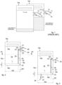
fig. 1 is a schematic front view related to two standard effluent bags known in the art; -
fig. 2 is a schematic front view of fluid collecting container according to the present invention; -
fig. 3 is a variant of the fluid collecting container offig. 2 ; -
fig. 4 is a section of the fluid collecting container taken along line III-III offig. 2 ; - fig. 5s is a schematic view of an extracorporeal blood treatment device according to the present invention.
- To facilitate comprehension, the same reference numbers have been used, where possible, to identify identical common elements in the drawings. It is understood that elements and characteristics of one embodiment can conveniently be incorporated into other embodiments without further clarifications.
- We will now refer in detail to the possible embodiments of the invention, of which one or more examples are shown in the attached drawings. Each example is supplied by way of illustration of the invention and shall not be understood as a limitation thereof. For example, one or more characteristics shown or described insomuch as they are part of one embodiment can be varied or adopted on, or in association with, other embodiments to produce further embodiments. It is understood that the present invention shall include all such modifications and variants.
- Before describing these embodiments, we must also clarify that the present description is not limited in its application to details of the construction and disposition of the components as described in the following description using the attached drawings. The present description can provide other embodiments and can be obtained or executed in various other ways. We must also clarify that the phraseology and terminology used here is for the purposes of description only and cannot be considered as limitative.
- With reference to the attached drawings, see for example
figs. 2-4 , afluid collecting container 15a comprises afluid inlet 20, afluid outlet 21, afront sheet 16 and aback sheet 17. Said front andback sheets edges chamber 19 in which the fluid can be collected. - The maximum capacity of the
chamber 19, when it is completely full, may range from 2 to 10 liters, more preferably from 5 to 8 liters, for example 7 liters. - The
fluid collecting container 15a comprises at least achannel 22 made in saidchamber 19. - The
channel 22 comprises a firstupper end 23 fluidically communicating with saidfluid inlet 20 and a secondbottom end 24 fluidically communicating with saidchamber 19. - The
channel 22 is configured to increase the pressure drop at thefluid inlet 20 once the fluid level L in saidchamber 19 reaches said secondbottom end 24. - The
fluid collecting container 15a can be in the form of a bag or a pouch and be made in PVC (Polyvinyl chloride) or other similar flexible thermoplastic materials suitable to be used in medical field, such as for example PE, PET, PMMA, PP or PA. - The
fluid inlet 20 and thefluid outlet 21 are fluidically communicating respectively with aninlet tube 25 andoutlet tube 26 where respective manual clamps 27 are positioned. - The
fluid inlet 20 is placed so as to lead the fluid entering the collectingcontainer 15a directly inside thechannel 22. Thefluid outlet 21 is located outside saidchannel 22. - In the exemplary embodiment of
fig. 2 , thefluid outlet 21 is located in the upper part of thefluid collecting container 15a, in particular above the fluid inlet 20.In the variant embodiment offig. 3 , thefluid outlet 21 is located in the bottom part of thefluid collecting container 15a, at thebottom edge 18d. Preferably, thefluid outlet 21 near thelateral edge 18a, namely in the side of the container further from thechannel 22 to avoid that the presence of thefluid outlet 21 may interfere with the filling of the collectingcontainer 15a through thechannel 22. - Said
channel 22 is formed by alateral edge 18c and by afirst weld part 28 and asecond weld part 29 that forms a substantially "L-shaped"weld 30. Theweld 30 connects along saidweld parts front sheet 16 and theback sheet 17 of thefluid collecting container 15a. - The
first weld part 28 is substantially horizontal, positioned above saidfluid inlet 20 and starting from thelateral edge 18c of thefluid collecting container 15a. In other words, thefirst weld part 28 is located above thefluid inlet 20 so that the latter lead the fluid into thechannel 22. - In another possible variant, the
first weld part 28 can be inclined respect to a horizontal line, for example of an acute angle, up to 30°. - The
second weld part 29 is substantially vertical, starting from the end of thefirst weld part 28 and its lower end defines said secondbottom end 24 of thechannel 22. - Said
second weld part 29 is substantially parallel to saidlateral edge 18c and thus the width W1 of thechannel 22 is constant. - Said width W1 of the
channel 22 can be 5-25% of the width W2 of thefluid collecting container 15a. - Between the
bottom edge 18d of thefluid collecting container 15a and said secondbottom end 24 of thechannel 22 there is defined a minimum distance D, dimensioned to allow the desired flowrate of the fluid from thechannel 22 toward thechamber 19. - In the examples shown in the figures attached, dimension D is substantially equal to the width W1 of the
channel 22. - The width W1 of the
channel 22 is basically defined by the length of thefirst weld part 28. Said length of thefirst weld part 28 can be 5-25% of the length of thesecond weld part 29. - Substantially, the
weld 30 allows to create aclosed channel 22 that increases the pressure drop in theinlet tube 25 once the liquid level L reaches theweld 30 itself, in particular thebottom end 24 of thechannel 22. Due to the design of theweld 30 and thus of thechannel 22, it is possible to ensure that thefluid collecting container 15a starts filling from the bottom side still maintaining thefluid inlet 20 in the upper part of thefluid collecting container 15a. - In
fig. 4 it is shown an extracorporealblood treatment device 31, comprising for example a blood treatment unit, provided with at least twofluids collecting containers liquid discharge line 32. The wastefluid discharge line 32 is divided into a first wastefluid discharge branch 33 connected to thefluid collecting container 15a and a second wastefluid discharge branch 34 connected to thefluid collecting container 15b. It should be noted that there may be additional branches and thus corresponding additional fluid collecting containers. -
Flush lines 35 connects theoutlet tubes 26 to any suitable waste disposal plant (not shown), for example comprising a reservoir or a sewerage. This allows to empties thefluid collecting containers - In the present
fluid collecting container 15a, the pressure drops in theinlet tube 25 is increased until the pressure drop in eachinlet tube 25 is greater than the pressure side effects generated by a sum of variables described above in the background section, for example non-return valve characteristics, adhesion of thesheets - The liquid is introduced in each fluid
liquid container inlet tube 25 and when the liquid level reaches thebottom end 24 of thechannel 22, the pressure increases in saidchannel 22, increasing the pressure drop in said inlet tube. - With this pressure drop increasing, the liquid prevalence is due only to liquid level that creates a huge pressure on respect to the above secondary variables; this new concept has been tested by simulating the issue related to the standard design of the bags according to the following procedure:
- connecting at least two
fluids collecting containers blood treatment device 31; - clamping one of the two fluid collecting
containers inlet tube 25; for example, clamping the inlet tube of thefluid collecting container 15a; - starting the priming procedure of the other
fluid collecting container 15b in which theinlet tube 25 is not clamped - observing the behavior of the
fluid collecting containers clamp 27 of theinlet tube 25 of thefluid collecting container 15a is opened. - As a result, once the clamped
fluid collecting container 15a is opened, it begins priming until the same liquid level of the otherfluid collecting container 15b is reached, then both thefluid collecting containers channel 22 realized in eachfluid collecting container fluid collecting containers latter containers - The present solution basically follows the Pascal principle which states that each variation of pressure in a closed recipient is transmitted equally to each part of the recipient and the liquid too.
- Thus, self-levelling
fluid collecting containers blood treatment device 31. - It is clear that modifications and/or additions of parts may be made to the fluid collecting container as described heretofore, without departing from the field and scope of the present invention, as defined by the claims.
- It is also clear that, although the present invention has been described with reference to some specific examples, a person of skill in the art shall certainly be able to achieve many other equivalent forms of fluid collecting container, having the characteristics as set forth in the claims and hence all coming within the field of protection defined thereby.
- In the following claims, the sole purpose of the references in brackets is to facilitate reading: they must not be considered as restrictive factors with regard to the field of protection claimed in the specific claims.
Claims (14)
- Fluid collecting container (15a, 15b), comprising a fluid inlet (20), a fluid outlet (21), a front sheet (16) and a back sheet (17), which are fixed together at their edges (18a, 18b, 18c, 18d) and create a chamber (19) in which the fluid can be collected, characterized in that it comprises a channel (22) realized in said chamber (19), provided with a first upper end (23) fluidically connected to said fluid inlet (20) and a second bottom end (24) fluidically connected to said chamber (19), said channel (22) being configured to increase the pressure drop at the fluid inlet (20) once the fluid level (L) in said chamber (19) reaches said second bottom end (24).
- Fluid collecting container (15a, 15b) according to claim 1, characterized in that it is in the form of a bag or a pouch and realized in PVC or other thermoplastic materials, such as for example PE, PET, PMMA, PP or PA.
- Fluid collecting container (15a, 15b) according to claim 1 or 2, characterized in that said fluid inlet (20) is placed so as to lead the fluid in said collecting container (15a, 15b) directly inside said channel (22) and said fluid outlet (21) is located outside said channel (22).
- Fluid collecting container (15a, 15b) according to any preceding claim, characterized in that said channel (22) is formed by a lateral edge (18c) of said fluid collecting containers (15a, 15b) and by a weld (30) that connects said front and back sheets (16, 17).
- Fluid collecting container (15a, 15b) according to claim 4, characterized in that said weld (30) comprises a first weld part (28) and a second weld part (29) positioned such that the weld (30) is substantially "L-shaped".
- Fluid collecting container (15a, 15b) according to claim 5, characterized in that said first weld part (28) is substantially horizontal, positioned above said fluid inlet (20) and starting from said lateral edge (18c) of the fluid collecting container (15a).
- Fluid collecting container (15a, 15b) according to claim 5 or 6, characterized in that said second weld part (29) is substantially vertical, starting from the end of the first weld part (28) and its lower end defines said second bottom end (24) of the channel (22).
- Fluid collecting container (15a, 15b) according to any one of claim 5 to 7, characterized in that said second weld part (29) is substantially parallel to said lateral edge (18c) and thus the width (W1) of the channel (22) is substantially constant.
- Fluid collecting container (15a, 15b) according to any one of the preceding claims, characterized in that a minimum distance (D) between a bottom edge (18d) of the fluid collecting container (15a, 15b) and said second bottom end (24) of the channel (22) is defined that is dimensioned to allow the desired flowrate of the fluid from said channel (22) toward said chamber (19).
- Fluid collecting container (15a, 15b) according to any one of the preceding claims, characterized in that the width (W1) of said channel (22) is 5-25% the width (W2) of the fluid collecting container (15a).
- Fluid collecting container (15a, 15b) according to any one of claims 5 to 10, when claims 9 and 10 depend on any of the claims 5-8, characterized in that the width (W1) of said channel (22) corresponds to the length of said first weld part (28), said length being 5-25% of the length of said second weld part (29).
- Fluid collecting container (15a, 15b) according to any one of the preceding claims, characterized in that the maximum capacity of said chamber (19) is comprised between 2 and 10 liters, preferably between 5 and 8 liters.
- Method to collect fluid in a fluid collecting container (15a, 15b), comprising a fluid inlet (20), a fluid outlet (21), a front sheet (16) and a back sheet (17) which are fixed together at their edges (18a, 18b, 18c, 18d) and create a chamber (19) in which the fluid can be collected, characterized in that it comprises:the realization of a channel (22) in said chamber (19), said channel (22) comprising a first upper end (23) fluidically connected to said fluid inlet (20) and a second bottom end (24) fluidically connected to said chamber (19);priming the fluid collecting container (15a, 15b) through said channel (22) and increasing the pressure drop at the fluid inlet (20) once the fluid level (L) in said chamber (19) reaches said second bottom end (24).
- Extracorporeal blood treatment device (31), comprising at least a waste liquid discharge line (32) and two or more fluid collecting containers (15a, 15b) as in any of the claims 1 to 12 that are connected in parallel to said waste liquid discharge line (32).
Priority Applications (4)
| Application Number | Priority Date | Filing Date | Title |
|---|---|---|---|
| EP22191058.1A EP4324496A1 (en) | 2022-08-18 | 2022-08-18 | Fluid collecting container |
| US18/451,575 US20240058517A1 (en) | 2022-08-18 | 2023-08-17 | Fluid collecting container |
| CN202311048676.3A CN117582563A (en) | 2022-08-18 | 2023-08-18 | Fluid collection container |
| CN202322246513.8U CN221998449U (en) | 2022-08-18 | 2023-08-18 | Fluid collection container and extracorporeal blood treatment device comprising same |
Applications Claiming Priority (1)
| Application Number | Priority Date | Filing Date | Title |
|---|---|---|---|
| EP22191058.1A EP4324496A1 (en) | 2022-08-18 | 2022-08-18 | Fluid collecting container |
Publications (1)
| Publication Number | Publication Date |
|---|---|
| EP4324496A1 true EP4324496A1 (en) | 2024-02-21 |
Family
ID=83004524
Family Applications (1)
| Application Number | Title | Priority Date | Filing Date |
|---|---|---|---|
| EP22191058.1A Pending EP4324496A1 (en) | 2022-08-18 | 2022-08-18 | Fluid collecting container |
Country Status (3)
| Country | Link |
|---|---|
| US (1) | US20240058517A1 (en) |
| EP (1) | EP4324496A1 (en) |
| CN (2) | CN221998449U (en) |
Citations (4)
| Publication number | Priority date | Publication date | Assignee | Title |
|---|---|---|---|---|
| US3985135A (en) * | 1975-03-31 | 1976-10-12 | Baxter Laboratories, Inc. | Dual chamber reservoir |
| US5431496A (en) * | 1993-01-19 | 1995-07-11 | Baxter International Inc. | Multiple chamber container |
| US20130078144A1 (en) * | 2008-01-22 | 2013-03-28 | Terumo Kabushiki Kaisha | Liquid collection container and extracorporeal circuit |
| US20190125952A1 (en) * | 2017-11-01 | 2019-05-02 | Baxter International Inc. | Mixing for online medical fluid generation |
-
2022
- 2022-08-18 EP EP22191058.1A patent/EP4324496A1/en active Pending
-
2023
- 2023-08-17 US US18/451,575 patent/US20240058517A1/en active Pending
- 2023-08-18 CN CN202322246513.8U patent/CN221998449U/en active Active
- 2023-08-18 CN CN202311048676.3A patent/CN117582563A/en active Pending
Patent Citations (4)
| Publication number | Priority date | Publication date | Assignee | Title |
|---|---|---|---|---|
| US3985135A (en) * | 1975-03-31 | 1976-10-12 | Baxter Laboratories, Inc. | Dual chamber reservoir |
| US5431496A (en) * | 1993-01-19 | 1995-07-11 | Baxter International Inc. | Multiple chamber container |
| US20130078144A1 (en) * | 2008-01-22 | 2013-03-28 | Terumo Kabushiki Kaisha | Liquid collection container and extracorporeal circuit |
| US20190125952A1 (en) * | 2017-11-01 | 2019-05-02 | Baxter International Inc. | Mixing for online medical fluid generation |
Also Published As
| Publication number | Publication date |
|---|---|
| CN117582563A (en) | 2024-02-23 |
| CN221998449U (en) | 2024-11-15 |
| US20240058517A1 (en) | 2024-02-22 |
Similar Documents
| Publication | Publication Date | Title |
|---|---|---|
| CA2680367C (en) | Pressure sensing device and use of the same in a connecting structure | |
| US8888755B2 (en) | Disposable bag comprising a multilayer film | |
| US11969534B2 (en) | Blood treatment device priming devices, methods, and systems | |
| US4559034A (en) | Line for use in body fluid treatment | |
| CN103687790B (en) | Fluid manifold system | |
| RU2166964C2 (en) | Device for carrying out peritoneal dialysis | |
| KR102708437B1 (en) | Method and device for emptying a effluent bag after blood treatment | |
| US9233196B2 (en) | Method for pre-filling a hemodialysis apparatus | |
| CN102438676A (en) | External functional device, blood treatment equipment and method for accommodating the external functional device of the present invention | |
| CN101189036A (en) | medical device | |
| US20210220537A1 (en) | Blood purification apparatus | |
| US20240058517A1 (en) | Fluid collecting container | |
| CA1194748A (en) | Infusion unit | |
| EP0902691B1 (en) | Soft tip blood reservoir for heart-lung machines | |
| EP1713431A1 (en) | A fluid bag, use of one or more fluid bags and a system including one or more fluid bags | |
| JP5260638B2 (en) | Blood processing apparatus and method with single needle operation | |
| JP6224048B2 (en) | Extracorporeal blood treatment device and collection container thereof | |
| WO2017069171A1 (en) | Blood purification device | |
| US3028863A (en) | Disposable enema units | |
| US3625216A (en) | Disposable water seal and suction control bag | |
| JP7135692B2 (en) | drainage system | |
| KR20200113257A (en) | Apparatus and method for determining patient static pressure | |
| US20170296735A1 (en) | Device with a bag-shaped container and method for filling a pump-operated hollow line-supported liquid circuit without forming gas bubbles using the device | |
| EP4160609A1 (en) | Detection of data entry errors for blood separation systems | |
| EP3842083B1 (en) | Blood purification apparatus |
Legal Events
| Date | Code | Title | Description |
|---|---|---|---|
| PUAI | Public reference made under article 153(3) epc to a published international application that has entered the european phase |
Free format text: ORIGINAL CODE: 0009012 |
|
| STAA | Information on the status of an ep patent application or granted ep patent |
Free format text: STATUS: THE APPLICATION HAS BEEN PUBLISHED |
|
| AK | Designated contracting states |
Kind code of ref document: A1 Designated state(s): AL AT BE BG CH CY CZ DE DK EE ES FI FR GB GR HR HU IE IS IT LI LT LU LV MC MK MT NL NO PL PT RO RS SE SI SK SM TR |
|
| STAA | Information on the status of an ep patent application or granted ep patent |
Free format text: STATUS: REQUEST FOR EXAMINATION WAS MADE |
|
| 17P | Request for examination filed |
Effective date: 20240807 |
|
| RBV | Designated contracting states (corrected) |
Designated state(s): AL AT BE BG CH CY CZ DE DK EE ES FI FR GB GR HR HU IE IS IT LI LT LU LV MC MK MT NL NO PL PT RO RS SE SI SK SM TR |