EP4322508A1 - Electronic device - Google Patents
Electronic device Download PDFInfo
- Publication number
- EP4322508A1 EP4322508A1 EP22783984.2A EP22783984A EP4322508A1 EP 4322508 A1 EP4322508 A1 EP 4322508A1 EP 22783984 A EP22783984 A EP 22783984A EP 4322508 A1 EP4322508 A1 EP 4322508A1
- Authority
- EP
- European Patent Office
- Prior art keywords
- bracket
- speaker
- main board
- electronic device
- display
- Prior art date
- Legal status (The legal status is an assumption and is not a legal conclusion. Google has not performed a legal analysis and makes no representation as to the accuracy of the status listed.)
- Pending
Links
Images




Classifications
-
- H—ELECTRICITY
- H04—ELECTRIC COMMUNICATION TECHNIQUE
- H04R—LOUDSPEAKERS, MICROPHONES, GRAMOPHONE PICK-UPS OR LIKE ACOUSTIC ELECTROMECHANICAL TRANSDUCERS; ELECTRIC HEARING AIDS; PUBLIC ADDRESS SYSTEMS
- H04R1/00—Details of transducers, loudspeakers or microphones
- H04R1/02—Casings; Cabinets ; Supports therefor; Mountings therein
- H04R1/025—Arrangements for fixing loudspeaker transducers, e.g. in a box, furniture
-
- H—ELECTRICITY
- H04—ELECTRIC COMMUNICATION TECHNIQUE
- H04M—TELEPHONIC COMMUNICATION
- H04M1/00—Substation equipment, e.g. for use by subscribers
- H04M1/02—Constructional features of telephone sets
- H04M1/03—Constructional features of telephone transmitters or receivers, e.g. telephone hand-sets
- H04M1/035—Improving the acoustic characteristics by means of constructional features of the housing, e.g. ribs, walls, resonating chambers or cavities
-
- H—ELECTRICITY
- H04—ELECTRIC COMMUNICATION TECHNIQUE
- H04M—TELEPHONIC COMMUNICATION
- H04M1/00—Substation equipment, e.g. for use by subscribers
- H04M1/02—Constructional features of telephone sets
- H04M1/0202—Portable telephone sets, e.g. cordless phones, mobile phones or bar type handsets
- H04M1/026—Details of the structure or mounting of specific components
-
- G—PHYSICS
- G06—COMPUTING OR CALCULATING; COUNTING
- G06F—ELECTRIC DIGITAL DATA PROCESSING
- G06F1/00—Details not covered by groups G06F3/00 - G06F13/00 and G06F21/00
- G06F1/16—Constructional details or arrangements
- G06F1/1613—Constructional details or arrangements for portable computers
- G06F1/1626—Constructional details or arrangements for portable computers with a single-body enclosure integrating a flat display, e.g. Personal Digital Assistants [PDAs]
-
- G—PHYSICS
- G06—COMPUTING OR CALCULATING; COUNTING
- G06F—ELECTRIC DIGITAL DATA PROCESSING
- G06F1/00—Details not covered by groups G06F3/00 - G06F13/00 and G06F21/00
- G06F1/16—Constructional details or arrangements
- G06F1/1613—Constructional details or arrangements for portable computers
- G06F1/1633—Constructional details or arrangements of portable computers not specific to the type of enclosures covered by groups G06F1/1615 - G06F1/1626
- G06F1/1637—Details related to the display arrangement, including those related to the mounting of the display in the housing
-
- G—PHYSICS
- G06—COMPUTING OR CALCULATING; COUNTING
- G06F—ELECTRIC DIGITAL DATA PROCESSING
- G06F1/00—Details not covered by groups G06F3/00 - G06F13/00 and G06F21/00
- G06F1/16—Constructional details or arrangements
- G06F1/1613—Constructional details or arrangements for portable computers
- G06F1/1633—Constructional details or arrangements of portable computers not specific to the type of enclosures covered by groups G06F1/1615 - G06F1/1626
- G06F1/1684—Constructional details or arrangements related to integrated I/O peripherals not covered by groups G06F1/1635 - G06F1/1675
- G06F1/1688—Constructional details or arrangements related to integrated I/O peripherals not covered by groups G06F1/1635 - G06F1/1675 the I/O peripheral being integrated loudspeakers
-
- H—ELECTRICITY
- H04—ELECTRIC COMMUNICATION TECHNIQUE
- H04R—LOUDSPEAKERS, MICROPHONES, GRAMOPHONE PICK-UPS OR LIKE ACOUSTIC ELECTROMECHANICAL TRANSDUCERS; ELECTRIC HEARING AIDS; PUBLIC ADDRESS SYSTEMS
- H04R1/00—Details of transducers, loudspeakers or microphones
- H04R1/02—Casings; Cabinets ; Supports therefor; Mountings therein
- H04R1/021—Casings; Cabinets ; Supports therefor; Mountings therein incorporating only one transducer
-
- H—ELECTRICITY
- H04—ELECTRIC COMMUNICATION TECHNIQUE
- H04R—LOUDSPEAKERS, MICROPHONES, GRAMOPHONE PICK-UPS OR LIKE ACOUSTIC ELECTROMECHANICAL TRANSDUCERS; ELECTRIC HEARING AIDS; PUBLIC ADDRESS SYSTEMS
- H04R1/00—Details of transducers, loudspeakers or microphones
- H04R1/02—Casings; Cabinets ; Supports therefor; Mountings therein
- H04R1/026—Supports for loudspeaker casings
-
- H—ELECTRICITY
- H04—ELECTRIC COMMUNICATION TECHNIQUE
- H04M—TELEPHONIC COMMUNICATION
- H04M1/00—Substation equipment, e.g. for use by subscribers
- H04M1/02—Constructional features of telephone sets
- H04M1/0202—Portable telephone sets, e.g. cordless phones, mobile phones or bar type handsets
- H04M1/026—Details of the structure or mounting of specific components
- H04M1/0266—Details of the structure or mounting of specific components for a display module assembly
-
- H—ELECTRICITY
- H04—ELECTRIC COMMUNICATION TECHNIQUE
- H04R—LOUDSPEAKERS, MICROPHONES, GRAMOPHONE PICK-UPS OR LIKE ACOUSTIC ELECTROMECHANICAL TRANSDUCERS; ELECTRIC HEARING AIDS; PUBLIC ADDRESS SYSTEMS
- H04R2499/00—Aspects covered by H04R or H04S not otherwise provided for in their subgroups
- H04R2499/10—General applications
- H04R2499/15—Transducers incorporated in visual displaying devices, e.g. televisions, computer displays, laptops
Definitions
- This application pertains to the field of communications technologies, and specifically relates to an electronic device.
- Existing speakers are generally classified as closed speakers, semi-open speakers, open speakers, and the like. Most electronic devices are provided with a semi-open speaker to lower costs; however, semi-open speakers generally have a large rear cavity. Therefore, the speaker occupies a relatively large space in existing electronic devices.
- Embodiments of this application are intended to provide an electronic device, which can solve the problem of a large space being occupied by a speaker in existing electronic devices.
- An embodiment of this application provides an electronic device, where the electronic device includes:
- the speaker disposed on the speaker bracket vibrates, it can vibrate the air in the closed rear cavity jointly created by the speaker bracket, the speaker, and the main board bracket.
- the closed rear cavity jointly created by the speaker bracket, the speaker, and the main board bracket can replace a speaker rear cavity created by other additional components. Therefore, in this embodiment of this application, fewer additional components are used for creating the speaker rear cavity, making the speaker occupy less space.
- fast-flowing gas generated during operation of the speaker cannot escape, thereby avoiding vibration caused by impact on other components of the electronic device, thus improving user experience.
- first”, “second”, and the like in this specification and claims of this application are used to distinguish between similar objects rather than to describe a specific order or sequence. It should be understood that the data used in this way is interchangeable in appropriate circumstances, such that the embodiments of this application can be implemented in other orders than the order illustrated or described herein.
- objects distinguished by “first”, “second”, and the like are generally of a same type, and the number of the objects are not limited. For example, there may be one or more first objects.
- “and/or” in the specification and claims represents at least one of connected objects, and the character “/" generally indicates that the associated objects have an "or” relationship.
- the electronic device includes a display bracket 100, a speaker bracket 200, a speaker 300, and a main board bracket 400.
- the display bracket 100 is a carrier of the display and other internal components of the electronic device, and also a mounting base for the speaker bracket 200.
- the speaker bracket 200 is disposed on the display bracket 100, and the speaker bracket 200 is a mounting base for the speaker 300.
- the speaker bracket 200 may further be provided with a limiting structure 203 for positioning the speaker 300.
- the limiting structure 203 can prevent the speaker 300 from moving within the electronic device, thereby avoiding effects on a sound-producing function of the speaker 300 and preventing the speaker 300 from colliding with other functional components within the electronic device.
- the speaker 300 is disposed on the speaker bracket 200, and the speaker 300 is on a side of the speaker bracket 200 back away from the display bracket 100.
- the speaker 300 vibrates surrounding air to generate a sound.
- the main board bracket 400 is connected to the display bracket 100, and the speaker bracket 200 and the speaker 300 are both located between the display bracket 100 and the main board bracket 400.
- the speaker bracket 200, the speaker 300, and the main board bracket 400 jointly create a closed rear cavity 910, and the speaker 300 vibrates air in the closed rear cavity 910 to generate a sound.
- a sealing component such as a double-sided adhesive or foam, may be used for sealing between the speaker bracket 200, the speaker 300, and the main board bracket 400, thereby completely sealing the closed rear cavity 910, thus preventing gas from escaping the closed rear cavity 910.
- the speaker 300 disposed on the speaker bracket 200 vibrates, it can vibrate the air in the closed rear cavity 910 jointly created by the speaker bracket 200, the speaker 300, and the main board bracket 400.
- the closed rear cavity 910 jointly created by the speaker bracket 200, the speaker 300, and the main board bracket 400 can replace a speaker rear cavity created by other additional components. Therefore, in this embodiment of this application, fewer additional components are used for creating the speaker rear cavity, making the speaker occupy less space.
- the closed rear cavity 910 created may be concentrated around the speaker 300, covering a smaller area, thus allowing easier sealing and lowering the risk of gas leak.
- the speaker bracket 200 is provided with a first through hole 201 to enlarge the closed rear cavity 910, where the first through hole 201 faces the display bracket 100, and the speaker bracket 200, the speaker 300, the main board bracket 400, and the display bracket 100 jointly create the closed rear cavity 910.
- the first through hole 201 is provided on the speaker bracket 200, so that the display bracket 100 can participate in creating the closed rear cavity 910. In this way, volume of the closed rear cavity 910 can be increased; and since the speaker bracket 200 is provided with the first through hole 201, the speaker bracket 200 can be made into a smaller size and in turn a smaller mass, so the entire electronic device can be made lighter.
- the electronic device includes a first main board 500, and the first main board 500 is disposed on the main board bracket 400.
- the first main board 500 may be connected to a side of the main board bracket 400, in which case the speaker bracket 200 and the first main board 500 may not be directly connected to each other.
- the speaker bracket 200, the speaker 300, the main board bracket 400, and the display bracket 100 jointly create the closed rear cavity 910, and the first main board 500 does not participate in creating the closed rear cavity 910.
- the speaker bracket 200, the speaker 300, the first main board 500, the main board bracket 400, and the display bracket 100 jointly create the closed rear cavity 910.
- the first main board 500 participates in creating the closed rear cavity 910, in which case the first main board 500 may be disposed between the speaker bracket 200 and the main board bracket 400, so that part of surface of the first main board 500 can be used for creating the closed rear cavity 910.
- the additional components used for creating the closed rear cavity 910 in the electronic device can be further reduced, or even no additional components are required for creating the closed rear cavity 910.
- this embodiment can further reduce the space occupied by the speaker.
- the first main board 500 may be totally provided on a side of the closed rear cavity 910.
- edge of the first main board 500 can only extend to edge of the closed rear cavity 910, resulting in a small area of the first main board 500, and consequently no additional components can be integrated on the first main board 500. Therefore, the first main board 500 may be provided with an avoidance hole 501, and a part of the speaker 300 is located in the avoidance hole 501. That is, the first main board 500 surrounds the speaker 300 via the avoidance hole 501, so the space around the speaker 300 can be utilized, and thus a first main board 500 having a larger area can be provided.
- a groove 401 is provided on a side of the main board bracket 400 facing the speaker bracket 200.
- the groove 401 is in communication with the avoidance hole 501, a part of the speaker 300 is located in the groove 401, and the closed rear cavity 910 includes a space created by side walls of the groove 401 and the speaker 300.
- the main board bracket 400 can be closer to the display bracket 100, so that the thickness of the electronic device can be smaller, improving the grip feeling of the user.
- the volume of the closed rear cavity 910 is not reduced even in a case that the main board bracket 400 is closer to the display bracket 100.
- the first main board 500 is attached to the main board bracket 400.
- the usable area of the first main board 500 is only its part not attached to the main board bracket 400, so only a small area of the first main board 500 can be utilized, causing a low utilization rate of the first main board 500. Therefore, in other embodiments, the main board bracket 400 includes a bracket body 410 and a protrusion portion 420.
- the protrusion portion 420 is provided on a side of the bracket body 410 facing the speaker bracket 200, the bracket body 410 and the protrusion portion 420 jointly form a groove 401, and a gap is present between the first main board 500 and the bracket body 410.
- the speaker 300 can be accommodated in the groove 401 formed by the bracket body 410 and the protrusion portion 420, thereby reducing the thickness of the electronic device.
- the gap between the first main board 500 and the bracket body 410 allows components to be arranged on both sides of the first main board 500, improving the utilization rate of the first main board 500.
- the gap between the first main board 500 and the bracket body 410 also allows heat generated by the first main board 500 to be led out, thereby improving a heat dissipation effect of the electronic device.
- an orthographic projection area of the groove 401 may be smaller or larger than an orthographic projection area of the avoidance hole 501 in a direction perpendicular to the first main board 500.
- a cover area of the groove 401 is smaller than the area of the avoidance hole 501, so that the volume of the closed rear cavity 910 is reduced; in the case that the orthographic projection of the groove 401 is larger than the orthographic projection of the avoidance hole 501, a part of the groove 401 presses the main board at a position close to the center of the main board, and as a result, the first main board 500 may be damaged in the presence of densely arranged components on the first main board 500.
- the orthographic projection of the groove 401 and the orthographic projection of the avoidance hole 501 can be made to coincide, so that not only the foregoing problems can be avoided, but also the closed rear cavity 910 created has a more regular shape, allowing more smooth gas flowing in the closed rear cavity 910.
- the first main board 500 can be supported by the speaker bracket 200 in the part where the first main board 500 is in contact with the protrusion portion 420, avoiding the problem that the first main board 500 is prone to bending.
- the first main board 500 may be fixedly connected to the display bracket 100 via a colloid, where the colloid may be an adhesive substance such as double-sided adhesive.
- the first main board 500 may be provided with a perforation 502, and the main board bracket 400 is fixedly connected to the display bracket 100 via a fastener 800.
- One end of the fastener 800 passes through the perforation 502, and the fastener 800 may be a screw, a bolt, or the like, which is not limited in this embodiment of this application.
- the connection between the main board bracket 400, the first main board 500, and the display bracket 100 can be made more secure and reliable by the fastener 800, and the sealing of the closed rear cavity 910 can be improved by the connection via the fastener 800.
- the electronic device may further include a second main board 600 and a support member 700.
- the second main board 600 is connected to the first main board 500 via the support member 700, and the second main board 600 is located in a space jointly created by the speaker bracket 200, the first main board 500, and the display bracket 100.
- more components can be integrated through the addition of the second main board 600, and the first main board 500 and the second main board 600 can be separated by the support member 700, preventing the interaction between the first main board 500 and the second main board 600.
- the space created by the speaker bracket 200, the first main board 500, and the display bracket 100 can be used to lead out heat generated by the first main board 500 and the second main board 600, thereby improving the heat dissipation effect of the electronic device.
- the display bracket 100 is provided with a sound output channel 101.
- the speaker bracket 200 is provided with a second through hole 202, and the second through hole 202 is in communication with the sound output channel 101.
- the display bracket 100, the speaker bracket 200, and the speaker 300 jointly create a speaker front cavity 920, and the speaker front cavity 920 is located on a side of the speaker 300 back away from the main board bracket 400.
- the speaker 300 provided on the speaker bracket 200 vibrates, it can vibrate the air in the speaker front cavity 920, thereby generating sound waves, and then lead out sound through the sound output channel 101, so that the user can hear the sound emitted by the electronic device.
- the second through hole 202 provided in the speaker bracket 200 can not only lead out the sound generated by the speaker 300 through the sound output channel 101, but also reduce the volume of the speaker bracket 200, thus reducing the weight of the speaker bracket 200 and in turn making the electronic device lighter.
- the electronic device disclosed in the embodiments of this application may be a smartphone, a tablet computer, an electronic book reader, a wearable device (such as a smart watch), an electronic game machine, or the like. Embodiments of this application do not limit the specific type of the electronic device.
Landscapes
- Engineering & Computer Science (AREA)
- Physics & Mathematics (AREA)
- Theoretical Computer Science (AREA)
- Computer Hardware Design (AREA)
- Signal Processing (AREA)
- Acoustics & Sound (AREA)
- Human Computer Interaction (AREA)
- General Engineering & Computer Science (AREA)
- General Physics & Mathematics (AREA)
- Details Of Audible-Bandwidth Transducers (AREA)
Abstract
Description
- The present invention claims priority to
Chinese Patent Application No. 202110367325.3, filed with the China National Intellectual Property Administration on April 06, 2021 - This application pertains to the field of communications technologies, and specifically relates to an electronic device.
- In existing electronic devices, multiple speakers are generally provided in order to meet the ever-increasing video and audio requirements of users.
- Existing speakers are generally classified as closed speakers, semi-open speakers, open speakers, and the like. Most electronic devices are provided with a semi-open speaker to lower costs; however, semi-open speakers generally have a large rear cavity. Therefore, the speaker occupies a relatively large space in existing electronic devices.
- Embodiments of this application are intended to provide an electronic device, which can solve the problem of a large space being occupied by a speaker in existing electronic devices.
- To resolve the foregoing technical problem, this application is implemented as follows.
- An embodiment of this application provides an electronic device, where the electronic device includes:
- a display bracket;
- a speaker bracket, where the speaker bracket is disposed on the display bracket;
- a speaker, where the speaker is disposed on the speaker bracket, and the speaker is located on a side of the speaker bracket back away from the display bracket; and
- a main board bracket, where the main board bracket is connected to the display bracket, and the speaker bracket and the speaker are both located between the display bracket and the main board bracket; where
- the speaker bracket, the speaker, and the main board bracket jointly create a closed rear cavity.
- In this embodiment of this application, in a case that the speaker disposed on the speaker bracket vibrates, it can vibrate the air in the closed rear cavity jointly created by the speaker bracket, the speaker, and the main board bracket. It can be seen that the closed rear cavity jointly created by the speaker bracket, the speaker, and the main board bracket can replace a speaker rear cavity created by other additional components. Therefore, in this embodiment of this application, fewer additional components are used for creating the speaker rear cavity, making the speaker occupy less space. In addition, due to good sealing of the closed rear cavity, fast-flowing gas generated during operation of the speaker cannot escape, thereby avoiding vibration caused by impact on other components of the electronic device, thus improving user experience.
-
-
FIG. 1 is an exploded view of a partial structure of an electronic device according to an embodiment of this application; -
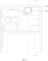
FIG. 2 andFIG. 3 are partial structural diagrams of an electronic device according to an embodiment of this application; -
FIG. 4 is a sectional view along A-A of the electronic device inFIG. 3 ; and -
FIG. 5 is a partial structural diagram of an electronic device according to another embodiment of this application. - Reference signs are described as follows:
- 100-display bracket, 101-sound output channel;
- 200-speaker bracket, 201-first through hole, 202-second through hole, 203-limiting structure;
- 300-speaker;
- 400-main board bracket, 401-groove, 410-bracket body, 420-protrusion portion;
- 500-first main board, 501-avoidance hole, 502-perforation;
- 600-second main board;
- 700-support member;
- 800-fastener; and
- 910-closed rear cavity, and 920-speaker front cavity.
- The following clearly and completely describes the technical solutions in the embodiments of this application with reference to the accompanying drawings in the embodiments of this application. Apparently, the described embodiments are some but not all of the embodiments of this application. All other embodiments obtained by persons of ordinary skill in the art based on the embodiments of this application without creative efforts shall fall within the protection scope of this application.
- The terms "first", "second", and the like in this specification and claims of this application are used to distinguish between similar objects rather than to describe a specific order or sequence. It should be understood that the data used in this way is interchangeable in appropriate circumstances, such that the embodiments of this application can be implemented in other orders than the order illustrated or described herein. In addition, objects distinguished by "first", "second", and the like are generally of a same type, and the number of the objects are not limited. For example, there may be one or more first objects. In addition, "and/or" in the specification and claims represents at least one of connected objects, and the character "/" generally indicates that the associated objects have an "or" relationship.
- With reference to the accompanying drawings, the following describes in detail the electronic device provided in embodiments of this application through specific embodiments and application scenarios thereof.
- As shown in
FIG. 1 to FIG. 4 , an electronic device is provided in an embodiment of this application. The electronic device includes adisplay bracket 100, aspeaker bracket 200, aspeaker 300, and amain board bracket 400. - The
display bracket 100 is a carrier of the display and other internal components of the electronic device, and also a mounting base for thespeaker bracket 200. - The
speaker bracket 200 is disposed on thedisplay bracket 100, and thespeaker bracket 200 is a mounting base for thespeaker 300. Thespeaker bracket 200 may further be provided with alimiting structure 203 for positioning thespeaker 300. Thelimiting structure 203 can prevent thespeaker 300 from moving within the electronic device, thereby avoiding effects on a sound-producing function of thespeaker 300 and preventing thespeaker 300 from colliding with other functional components within the electronic device. - The
speaker 300 is disposed on thespeaker bracket 200, and thespeaker 300 is on a side of thespeaker bracket 200 back away from thedisplay bracket 100. Thespeaker 300 vibrates surrounding air to generate a sound. - The
main board bracket 400 is connected to thedisplay bracket 100, and thespeaker bracket 200 and thespeaker 300 are both located between thedisplay bracket 100 and themain board bracket 400. - The
speaker bracket 200, thespeaker 300, and themain board bracket 400 jointly create a closedrear cavity 910, and thespeaker 300 vibrates air in the closedrear cavity 910 to generate a sound. A sealing component such as a double-sided adhesive or foam, may be used for sealing between thespeaker bracket 200, thespeaker 300, and themain board bracket 400, thereby completely sealing the closedrear cavity 910, thus preventing gas from escaping the closedrear cavity 910. - In this embodiment of this application, in a case that the
speaker 300 disposed on thespeaker bracket 200 vibrates, it can vibrate the air in the closedrear cavity 910 jointly created by thespeaker bracket 200, thespeaker 300, and themain board bracket 400. It can be seen that the closedrear cavity 910 jointly created by thespeaker bracket 200, thespeaker 300, and themain board bracket 400 can replace a speaker rear cavity created by other additional components. Therefore, in this embodiment of this application, fewer additional components are used for creating the speaker rear cavity, making the speaker occupy less space. In addition, due to good sealing of the closedrear cavity 910, fast-flowing gas generated during operation of thespeaker 300 cannot escape, thereby avoiding vibration caused by impact on other components of the electronic device, thus improving user experience. Furthermore, the closedrear cavity 910 created may be concentrated around thespeaker 300, covering a smaller area, thus allowing easier sealing and lowering the risk of gas leak. - As the size of the closed
rear cavity 910 of the speaker affects sound quality of the speaker, in an embodiment, thespeaker bracket 200 is provided with a first throughhole 201 to enlarge the closedrear cavity 910, where the first throughhole 201 faces thedisplay bracket 100, and thespeaker bracket 200, thespeaker 300, themain board bracket 400, and thedisplay bracket 100 jointly create the closedrear cavity 910. In this embodiment, the first throughhole 201 is provided on thespeaker bracket 200, so that thedisplay bracket 100 can participate in creating the closedrear cavity 910. In this way, volume of the closedrear cavity 910 can be increased; and since thespeaker bracket 200 is provided with the first throughhole 201, thespeaker bracket 200 can be made into a smaller size and in turn a smaller mass, so the entire electronic device can be made lighter. - Further, the electronic device includes a first
main board 500, and the firstmain board 500 is disposed on themain board bracket 400. Optionally, the firstmain board 500 may be connected to a side of themain board bracket 400, in which case thespeaker bracket 200 and the firstmain board 500 may not be directly connected to each other. In this embodiment, thespeaker bracket 200, thespeaker 300, themain board bracket 400, and thedisplay bracket 100 jointly create the closedrear cavity 910, and the firstmain board 500 does not participate in creating the closedrear cavity 910. In another embodiment, thespeaker bracket 200, thespeaker 300, the firstmain board 500, themain board bracket 400, and thedisplay bracket 100 jointly create the closedrear cavity 910. That is, the firstmain board 500 participates in creating the closedrear cavity 910, in which case the firstmain board 500 may be disposed between thespeaker bracket 200 and themain board bracket 400, so that part of surface of the firstmain board 500 can be used for creating the closedrear cavity 910. As the firstmain board 500 can also participate in creating the closedrear cavity 910, the additional components used for creating the closedrear cavity 910 in the electronic device can be further reduced, or even no additional components are required for creating the closedrear cavity 910. Thus, this embodiment can further reduce the space occupied by the speaker. - In a further embodiment, the first
main board 500 may be totally provided on a side of the closedrear cavity 910. In this case, since the firstmain board 500 has to create the closedrear cavity 910 together with thespeaker bracket 200, thespeaker 300, themain board bracket 400, and thedisplay bracket 100, edge of the firstmain board 500 can only extend to edge of the closedrear cavity 910, resulting in a small area of the firstmain board 500, and consequently no additional components can be integrated on the firstmain board 500. Therefore, the firstmain board 500 may be provided with anavoidance hole 501, and a part of thespeaker 300 is located in theavoidance hole 501. That is, the firstmain board 500 surrounds thespeaker 300 via theavoidance hole 501, so the space around thespeaker 300 can be utilized, and thus a firstmain board 500 having a larger area can be provided. - In a further optional embodiment, in the case that the
main board bracket 400 participates in creating the closedrear cavity 910, the electronic device will have an increased thickness due to the thickness of themain board bracket 400, affecting grip feeling of the user using the electronic device. Therefore, agroove 401 is provided on a side of themain board bracket 400 facing thespeaker bracket 200. Thegroove 401 is in communication with theavoidance hole 501, a part of thespeaker 300 is located in thegroove 401, and the closedrear cavity 910 includes a space created by side walls of thegroove 401 and thespeaker 300. In the foregoing implementation, since a part of thespeaker 300 can be located in thegroove 401, themain board bracket 400 can be closer to thedisplay bracket 100, so that the thickness of the electronic device can be smaller, improving the grip feeling of the user. In addition, in this case, due to the existence of thegroove 401, the volume of the closedrear cavity 910 is not reduced even in a case that themain board bracket 400 is closer to thedisplay bracket 100. - In an optional embodiment, the first
main board 500 is attached to themain board bracket 400. In this arrangement, the usable area of the firstmain board 500 is only its part not attached to themain board bracket 400, so only a small area of the firstmain board 500 can be utilized, causing a low utilization rate of the firstmain board 500. Therefore, in other embodiments, themain board bracket 400 includes abracket body 410 and aprotrusion portion 420. Theprotrusion portion 420 is provided on a side of thebracket body 410 facing thespeaker bracket 200, thebracket body 410 and theprotrusion portion 420 jointly form agroove 401, and a gap is present between the firstmain board 500 and thebracket body 410. In this embodiment, thespeaker 300 can be accommodated in thegroove 401 formed by thebracket body 410 and theprotrusion portion 420, thereby reducing the thickness of the electronic device. Moreover, the gap between the firstmain board 500 and thebracket body 410 allows components to be arranged on both sides of the firstmain board 500, improving the utilization rate of the firstmain board 500. In addition, the gap between the firstmain board 500 and thebracket body 410 also allows heat generated by the firstmain board 500 to be led out, thereby improving a heat dissipation effect of the electronic device. - In another optional embodiment, an orthographic projection area of the
groove 401 may be smaller or larger than an orthographic projection area of theavoidance hole 501 in a direction perpendicular to the firstmain board 500. In the case that the orthographic projection area of thegroove 401 is smaller than the orthographic projection area of theavoidance hole 501, a cover area of thegroove 401 is smaller than the area of theavoidance hole 501, so that the volume of the closedrear cavity 910 is reduced; in the case that the orthographic projection of thegroove 401 is larger than the orthographic projection of theavoidance hole 501, a part of thegroove 401 presses the main board at a position close to the center of the main board, and as a result, the firstmain board 500 may be damaged in the presence of densely arranged components on the firstmain board 500. Therefore, the orthographic projection of thegroove 401 and the orthographic projection of theavoidance hole 501 can be made to coincide, so that not only the foregoing problems can be avoided, but also the closedrear cavity 910 created has a more regular shape, allowing more smooth gas flowing in the closedrear cavity 910. In addition, with the orthographic projection of thegroove 401 coinciding with the orthographic projection of theavoidance hole 501, the firstmain board 500 can be supported by thespeaker bracket 200 in the part where the firstmain board 500 is in contact with theprotrusion portion 420, avoiding the problem that the firstmain board 500 is prone to bending. - In an embodiment, the first
main board 500 may be fixedly connected to thedisplay bracket 100 via a colloid, where the colloid may be an adhesive substance such as double-sided adhesive. However, in this manner, the adhesion of the colloid is impacted by high temperatures, and therefore, the manner has poor reliability. Therefore, the firstmain board 500 may be provided with aperforation 502, and themain board bracket 400 is fixedly connected to thedisplay bracket 100 via afastener 800. One end of thefastener 800 passes through theperforation 502, and thefastener 800 may be a screw, a bolt, or the like, which is not limited in this embodiment of this application. The connection between themain board bracket 400, the firstmain board 500, and thedisplay bracket 100 can be made more secure and reliable by thefastener 800, and the sealing of the closedrear cavity 910 can be improved by the connection via thefastener 800. - In another embodiment, in a case that there is only the first
main board 500 in the electronic device, fewer components can be integrated on the firstmain board 500 due to a limited area. Therefore, as shown inFIG. 5 , the electronic device may further include a secondmain board 600 and asupport member 700. The secondmain board 600 is connected to the firstmain board 500 via thesupport member 700, and the secondmain board 600 is located in a space jointly created by thespeaker bracket 200, the firstmain board 500, and thedisplay bracket 100. In this embodiment, more components can be integrated through the addition of the secondmain board 600, and the firstmain board 500 and the secondmain board 600 can be separated by thesupport member 700, preventing the interaction between the firstmain board 500 and the secondmain board 600. In addition, the space created by thespeaker bracket 200, the firstmain board 500, and thedisplay bracket 100 can be used to lead out heat generated by the firstmain board 500 and the secondmain board 600, thereby improving the heat dissipation effect of the electronic device. - In an optional embodiment, the
display bracket 100 is provided with asound output channel 101. Thespeaker bracket 200 is provided with a second throughhole 202, and the second throughhole 202 is in communication with thesound output channel 101. Thedisplay bracket 100, thespeaker bracket 200, and thespeaker 300 jointly create aspeaker front cavity 920, and thespeaker front cavity 920 is located on a side of thespeaker 300 back away from themain board bracket 400. In a case that thespeaker 300 provided on thespeaker bracket 200 vibrates, it can vibrate the air in thespeaker front cavity 920, thereby generating sound waves, and then lead out sound through thesound output channel 101, so that the user can hear the sound emitted by the electronic device. The second throughhole 202 provided in thespeaker bracket 200 can not only lead out the sound generated by thespeaker 300 through thesound output channel 101, but also reduce the volume of thespeaker bracket 200, thus reducing the weight of thespeaker bracket 200 and in turn making the electronic device lighter. - The electronic device disclosed in the embodiments of this application may be a smartphone, a tablet computer, an electronic book reader, a wearable device (such as a smart watch), an electronic game machine, or the like. Embodiments of this application do not limit the specific type of the electronic device.
- The foregoing describes the embodiments of this application with reference to the accompanying drawings. However, this application is not limited to the foregoing specific implementations. These specific implementations are merely illustrative rather than restrictive. Inspired by this application, persons of ordinary skill in the art may develop many other forms without departing from the essence of this application and the protection scope of the claims, and all such forms shall fall within the protection scope of this application.
Claims (10)
- An electronic device, comprising:a display bracket;a speaker bracket, wherein the speaker bracket is disposed on the display bracket;a speaker, wherein the speaker is disposed on the speaker bracket, and the speaker is located on a side of the speaker bracket back away from the display bracket; anda main board bracket, wherein the main board bracket is connected to the display bracket, and the speaker bracket and the speaker are both located between the display bracket and the main board bracket; whereinthe speaker bracket, the speaker, and the main board bracket jointly create a closed rear cavity.
- The electronic device according to claim 1, wherein the speaker bracket is provided with a first through hole, wherein the first through hole faces the display bracket, and the speaker bracket, the speaker, the main board bracket, and the display bracket jointly create the closed rear cavity.
- The electronic device according to claim 2, wherein the electronic device further comprises a first main board, wherein the first main board is disposed on the main board bracket, the speaker bracket is connected to the first main board, the speaker bracket is located on a side of the first main board back away from the main board bracket, and the speaker bracket, the speaker, the first main board, the main board bracket, and the display bracket jointly create the closed rear cavity.
- The electronic device according to claim 3, wherein the first main board is provided with an avoidance hole, and a part of the speaker is located in the avoidance hole.
- The electronic device according to claim 4, wherein a side of the main board bracket facing the speaker bracket is provided with a groove, wherein the groove is in communication with the avoidance hole, a part of the speaker is located in the groove, and the closed rear cavity comprises a space enclosed by side walls of the groove and the speaker.
- The electronic device according to claim 5, wherein the main board bracket comprises a bracket body and a protrusion portion, wherein the protrusion portion is disposed on a surface of the bracket body facing the speaker bracket, the bracket body and the protrusion portion jointly form the groove, and a gap is present between the first main board and the bracket body.
- The electronic device according to claim 5, wherein in a direction perpendicular to the first main board, an orthographic projection of the groove coincides with an orthographic projection of the avoidance hole.
- The electronic device according to claim 3, wherein the first main board is provided with a perforation, the main board bracket is fixedly connected to the display bracket via a fastener, and one end of the fastener passes through the perforation.
- The electronic device according to claim 3, wherein the electronic device further comprises a second main board and a support member, wherein the second main board is connected to the first main board via the support member, and the second main board is located in a space jointly created by the speaker bracket, the first main board, and the display bracket.
- The electronic device according to claim 1, wherein the display bracket is provided with a sound output channel, the speaker bracket is provided with a second through hole, the second through hole is in communication with the sound output channel, and the display bracket, the speaker bracket, and the speaker jointly create a speaker front cavity, the speaker front cavity is located on a side of the speaker back away from the main board bracket.
Applications Claiming Priority (2)
| Application Number | Priority Date | Filing Date | Title |
|---|---|---|---|
| CN202110367325.3A CN113099003B (en) | 2021-04-06 | 2021-04-06 | Electronic device |
| PCT/CN2022/085025 WO2022213918A1 (en) | 2021-04-06 | 2022-04-02 | Electronic device |
Publications (2)
| Publication Number | Publication Date |
|---|---|
| EP4322508A1 true EP4322508A1 (en) | 2024-02-14 |
| EP4322508A4 EP4322508A4 (en) | 2024-10-02 |
Family
ID=76674231
Family Applications (1)
| Application Number | Title | Priority Date | Filing Date |
|---|---|---|---|
| EP22783984.2A Pending EP4322508A4 (en) | 2021-04-06 | 2022-04-02 | Electronic device |
Country Status (5)
| Country | Link |
|---|---|
| US (1) | US12532097B2 (en) |
| EP (1) | EP4322508A4 (en) |
| KR (1) | KR102844731B1 (en) |
| CN (1) | CN113099003B (en) |
| WO (1) | WO2022213918A1 (en) |
Cited By (1)
| Publication number | Priority date | Publication date | Assignee | Title |
|---|---|---|---|---|
| EP4354833A4 (en) * | 2021-06-09 | 2024-10-09 | Vivo Mobile Communication Co., Ltd. | Electronic device |
Families Citing this family (2)
| Publication number | Priority date | Publication date | Assignee | Title |
|---|---|---|---|---|
| CN113099003B (en) | 2021-04-06 | 2023-03-31 | 维沃移动通信有限公司 | Electronic device |
| CN117412228B (en) * | 2023-09-20 | 2025-09-09 | 荣耀终端股份有限公司 | Electronic equipment |
Family Cites Families (11)
| Publication number | Priority date | Publication date | Assignee | Title |
|---|---|---|---|---|
| CN102340710B (en) * | 2010-07-21 | 2014-03-26 | 深圳富泰宏精密工业有限公司 | Electronic device with voice function |
| JP2013255021A (en) * | 2012-06-05 | 2013-12-19 | Nec Casio Mobile Communications Ltd | Portable terminal device and assembly method of the same |
| CN202679442U (en) * | 2012-06-19 | 2013-01-16 | 惠州Tcl移动通信有限公司 | Cell phone and sound chamber structure thereof |
| EP3104250A1 (en) * | 2015-06-10 | 2016-12-14 | FairPhone B.V. | Modular electronic device |
| CN106412776B (en) * | 2016-11-04 | 2020-05-19 | 惠州Tcl移动通信有限公司 | Mobile terminal and loudspeaker assembly thereof |
| CN106714047B (en) * | 2016-11-29 | 2019-08-30 | 努比亚技术有限公司 | A kind of audio cavity structure and mobile terminal |
| CN209046878U (en) * | 2018-11-29 | 2019-06-28 | Oppo(重庆)智能科技有限公司 | A kind of electronic equipment |
| KR102573519B1 (en) * | 2018-12-04 | 2023-09-04 | 삼성전자주식회사 | Electronic device including speaker module |
| CN112261203B (en) * | 2020-10-22 | 2022-06-10 | 维沃移动通信有限公司 | Electronic equipment and control method and control device thereof |
| CN112291394A (en) * | 2020-10-29 | 2021-01-29 | 维沃移动通信有限公司 | Electronic device |
| CN113099003B (en) * | 2021-04-06 | 2023-03-31 | 维沃移动通信有限公司 | Electronic device |
-
2021
- 2021-04-06 CN CN202110367325.3A patent/CN113099003B/en active Active
-
2022
- 2022-04-02 EP EP22783984.2A patent/EP4322508A4/en active Pending
- 2022-04-02 KR KR1020237029699A patent/KR102844731B1/en active Active
- 2022-04-02 WO PCT/CN2022/085025 patent/WO2022213918A1/en not_active Ceased
-
2023
- 2023-09-26 US US18/474,413 patent/US12532097B2/en active Active
Cited By (1)
| Publication number | Priority date | Publication date | Assignee | Title |
|---|---|---|---|---|
| EP4354833A4 (en) * | 2021-06-09 | 2024-10-09 | Vivo Mobile Communication Co., Ltd. | Electronic device |
Also Published As
| Publication number | Publication date |
|---|---|
| WO2022213918A1 (en) | 2022-10-13 |
| US20240022843A1 (en) | 2024-01-18 |
| CN113099003A (en) | 2021-07-09 |
| KR20230133929A (en) | 2023-09-19 |
| KR102844731B1 (en) | 2025-08-11 |
| CN113099003B (en) | 2023-03-31 |
| EP4322508A4 (en) | 2024-10-02 |
| US12532097B2 (en) | 2026-01-20 |
Similar Documents
| Publication | Publication Date | Title |
|---|---|---|
| US12532097B2 (en) | Electronic device | |
| US12137320B2 (en) | Speaker and terminal | |
| JP7514394B2 (en) | Electronics | |
| US8942410B2 (en) | Magnetically biased electromagnet for audio applications | |
| EP4354833A1 (en) | Electronic device | |
| CN113490086A (en) | Electronic device | |
| CN209046878U (en) | A kind of electronic equipment | |
| CN106603775A (en) | Mobile terminal | |
| WO2021244365A1 (en) | Electronic device | |
| WO2021190209A1 (en) | Electronic apparatus | |
| CN215499051U (en) | Electronic equipment | |
| US11425504B2 (en) | Acoustic module and electronic product | |
| JP2013090336A (en) | Portable terminal | |
| CN106453759A (en) | Mobile device | |
| CN217010936U (en) | Electronic device | |
| CN214101676U (en) | Electronic equipment | |
| JP2005033723A (en) | Mobile terminal device | |
| CN206542463U (en) | Mobile terminal | |
| JP6874613B2 (en) | Electronics | |
| CN112911037A (en) | Electronic device | |
| WO2021169410A1 (en) | Vibration component of electronic device and electronic device | |
| CN210466214U (en) | tablet | |
| TWM597546U (en) | Speaker unit with microphone | |
| JP2007036871A (en) | Mobile terminal device | |
| JP2013102528A (en) | Sound emission structure of housing and electronic equipment |
Legal Events
| Date | Code | Title | Description |
|---|---|---|---|
| STAA | Information on the status of an ep patent application or granted ep patent |
Free format text: STATUS: THE INTERNATIONAL PUBLICATION HAS BEEN MADE |
|
| PUAI | Public reference made under article 153(3) epc to a published international application that has entered the european phase |
Free format text: ORIGINAL CODE: 0009012 |
|
| STAA | Information on the status of an ep patent application or granted ep patent |
Free format text: STATUS: REQUEST FOR EXAMINATION WAS MADE |
|
| 17P | Request for examination filed |
Effective date: 20230922 |
|
| AK | Designated contracting states |
Kind code of ref document: A1 Designated state(s): AL AT BE BG CH CY CZ DE DK EE ES FI FR GB GR HR HU IE IS IT LI LT LU LV MC MK MT NL NO PL PT RO RS SE SI SK SM TR |
|
| DAV | Request for validation of the european patent (deleted) | ||
| DAX | Request for extension of the european patent (deleted) | ||
| A4 | Supplementary search report drawn up and despatched |
Effective date: 20240829 |
|
| RIC1 | Information provided on ipc code assigned before grant |
Ipc: H04R 1/02 20060101ALI20240823BHEP Ipc: H04M 1/03 20060101ALI20240823BHEP Ipc: G06F 1/16 20060101ALI20240823BHEP Ipc: H04M 1/02 20060101AFI20240823BHEP |