EP4322282A1 - Three-electrode cell structure and preparation method therefor, and method for testing negative electrode potential - Google Patents
Three-electrode cell structure and preparation method therefor, and method for testing negative electrode potential Download PDFInfo
- Publication number
- EP4322282A1 EP4322282A1 EP22819171.4A EP22819171A EP4322282A1 EP 4322282 A1 EP4322282 A1 EP 4322282A1 EP 22819171 A EP22819171 A EP 22819171A EP 4322282 A1 EP4322282 A1 EP 4322282A1
- Authority
- EP
- European Patent Office
- Prior art keywords
- electrode
- separator membrane
- negative electrode
- end head
- reference electrode
- Prior art date
- Legal status (The legal status is an assumption and is not a legal conclusion. Google has not performed a legal analysis and makes no representation as to the accuracy of the status listed.)
- Pending
Links
Images

Classifications
-
- H—ELECTRICITY
- H01—ELECTRIC ELEMENTS
- H01M—PROCESSES OR MEANS, e.g. BATTERIES, FOR THE DIRECT CONVERSION OF CHEMICAL ENERGY INTO ELECTRICAL ENERGY
- H01M10/00—Secondary cells; Manufacture thereof
- H01M10/42—Methods or arrangements for servicing or maintenance of secondary cells or secondary half-cells
- H01M10/48—Accumulators combined with arrangements for measuring, testing or indicating the condition of cells, e.g. the level or density of the electrolyte
-
- G—PHYSICS
- G01—MEASURING; TESTING
- G01R—MEASURING ELECTRIC VARIABLES; MEASURING MAGNETIC VARIABLES
- G01R19/00—Arrangements for measuring currents or voltages or for indicating presence or sign thereof
- G01R19/0084—Measuring voltage only
-
- H—ELECTRICITY
- H01—ELECTRIC ELEMENTS
- H01M—PROCESSES OR MEANS, e.g. BATTERIES, FOR THE DIRECT CONVERSION OF CHEMICAL ENERGY INTO ELECTRICAL ENERGY
- H01M10/00—Secondary cells; Manufacture thereof
- H01M10/05—Accumulators with non-aqueous electrolyte
- H01M10/052—Li-accumulators
-
- H—ELECTRICITY
- H01—ELECTRIC ELEMENTS
- H01M—PROCESSES OR MEANS, e.g. BATTERIES, FOR THE DIRECT CONVERSION OF CHEMICAL ENERGY INTO ELECTRICAL ENERGY
- H01M10/00—Secondary cells; Manufacture thereof
- H01M10/05—Accumulators with non-aqueous electrolyte
- H01M10/052—Li-accumulators
- H01M10/0525—Rocking-chair batteries, i.e. batteries with lithium insertion or intercalation in both electrodes; Lithium-ion batteries
-
- H—ELECTRICITY
- H01—ELECTRIC ELEMENTS
- H01M—PROCESSES OR MEANS, e.g. BATTERIES, FOR THE DIRECT CONVERSION OF CHEMICAL ENERGY INTO ELECTRICAL ENERGY
- H01M10/00—Secondary cells; Manufacture thereof
- H01M10/05—Accumulators with non-aqueous electrolyte
- H01M10/058—Construction or manufacture
- H01M10/0585—Construction or manufacture of accumulators having only flat construction elements, i.e. flat positive electrodes, flat negative electrodes and flat separators
-
- H—ELECTRICITY
- H01—ELECTRIC ELEMENTS
- H01M—PROCESSES OR MEANS, e.g. BATTERIES, FOR THE DIRECT CONVERSION OF CHEMICAL ENERGY INTO ELECTRICAL ENERGY
- H01M10/00—Secondary cells; Manufacture thereof
- H01M10/05—Accumulators with non-aqueous electrolyte
- H01M10/058—Construction or manufacture
- H01M10/0587—Construction or manufacture of accumulators having only wound construction elements, i.e. wound positive electrodes, wound negative electrodes and wound separators
-
- H—ELECTRICITY
- H01—ELECTRIC ELEMENTS
- H01M—PROCESSES OR MEANS, e.g. BATTERIES, FOR THE DIRECT CONVERSION OF CHEMICAL ENERGY INTO ELECTRICAL ENERGY
- H01M10/00—Secondary cells; Manufacture thereof
- H01M10/42—Methods or arrangements for servicing or maintenance of secondary cells or secondary half-cells
- H01M10/4235—Safety or regulating additives or arrangements in electrodes, separators or electrolyte
-
- H—ELECTRICITY
- H01—ELECTRIC ELEMENTS
- H01M—PROCESSES OR MEANS, e.g. BATTERIES, FOR THE DIRECT CONVERSION OF CHEMICAL ENERGY INTO ELECTRICAL ENERGY
- H01M2220/00—Batteries for particular applications
- H01M2220/20—Batteries in motive systems, e.g. vehicle, ship, plane
-
- H—ELECTRICITY
- H01—ELECTRIC ELEMENTS
- H01M—PROCESSES OR MEANS, e.g. BATTERIES, FOR THE DIRECT CONVERSION OF CHEMICAL ENERGY INTO ELECTRICAL ENERGY
- H01M2220/00—Batteries for particular applications
- H01M2220/30—Batteries in portable systems, e.g. mobile phone, laptop
-
- Y—GENERAL TAGGING OF NEW TECHNOLOGICAL DEVELOPMENTS; GENERAL TAGGING OF CROSS-SECTIONAL TECHNOLOGIES SPANNING OVER SEVERAL SECTIONS OF THE IPC; TECHNICAL SUBJECTS COVERED BY FORMER USPC CROSS-REFERENCE ART COLLECTIONS [XRACs] AND DIGESTS
- Y02—TECHNOLOGIES OR APPLICATIONS FOR MITIGATION OR ADAPTATION AGAINST CLIMATE CHANGE
- Y02E—REDUCTION OF GREENHOUSE GAS [GHG] EMISSIONS, RELATED TO ENERGY GENERATION, TRANSMISSION OR DISTRIBUTION
- Y02E60/00—Enabling technologies; Technologies with a potential or indirect contribution to GHG emissions mitigation
- Y02E60/10—Energy storage using batteries
-
- Y—GENERAL TAGGING OF NEW TECHNOLOGICAL DEVELOPMENTS; GENERAL TAGGING OF CROSS-SECTIONAL TECHNOLOGIES SPANNING OVER SEVERAL SECTIONS OF THE IPC; TECHNICAL SUBJECTS COVERED BY FORMER USPC CROSS-REFERENCE ART COLLECTIONS [XRACs] AND DIGESTS
- Y02—TECHNOLOGIES OR APPLICATIONS FOR MITIGATION OR ADAPTATION AGAINST CLIMATE CHANGE
- Y02P—CLIMATE CHANGE MITIGATION TECHNOLOGIES IN THE PRODUCTION OR PROCESSING OF GOODS
- Y02P70/00—Climate change mitigation technologies in the production process for final industrial or consumer products
- Y02P70/50—Manufacturing or production processes characterised by the final manufactured product
Definitions
- the present invention relates to the field of batteries, in particular to a three-electrode cell structure and a preparation method therefor, and a method for testing an electric potential of a negative electrode.
- Lithium batteries as a power source for electronic products, are widely used and essential in social life.
- the increasing consumption of fossil energy on Earth and the resulted environmental issues have also sounded an alarm for human energy applications.
- replacing existing fossil energy with electric energy for driving vehicles, namely developing power battery vehicles has become one of the efforts of various countries.
- methods for judging lithium precipitation of the cells include: 1, a three-electrode method, taking an electric potential of a negative electrode of 0 V as a standard for negative electrode lithium precipitation; 2, a voltage relaxation curve method, taking whether there is a characteristic peak in a voltage curve in a standing state after charging as a judging standard for lithium precipitation; 3, a discharge capacity differential curve method, judging whether lithium precipitation occurs by observing whether there is a characteristic peak in a capacity differential curve in a discharging process; and 4, a visual method, mainly, disassembling the cells in a cycling process in a fully charged state, observing a negative electrode interface and judging whether lithium precipitation occurs.
- the voltage relaxation curve and discharge capacity differential curve methods have obvious characteristic peaks when lithium precipitation occurs at a low temperature in the cells, but the characteristic peaks are difficult to observe at a room temperature, such that there are certain limitations.
- the visual method requires a long-time cycling test to judge whether lithium precipitation occurs through cycling disassembly, the time consumption is long, and costs are high.
- the method for judging whether lithium precipitation occurs by disassembling a battery to observe a negative electrode interface is affected by human influence greatly due to the limitations of human visual observation, which will result in errors in the judgment of results and cannot be quantified through specific data.
- a relatively mature method is to judge whether lithium precipitation occurs through a three-electrode cell, with the electric potential of the negative electrode of 0 V as a standard. When the electric potential of the negative electrode is less than 0 V, it is considered that lithium precipitation occurs.
- the separator membrane is introduced into the production process to generate polarization, which will cause a certain deviation in test results of three electrodes, and correction is required.
- a main objective of the present invention is to provide a three-electrode cell structure and a preparation method therefor, and a method for testing an electric potential of a negative electrode, so as to solve the problem of inaccurate test results caused by polarization generated by the introduction of a separator membrane when using a three-electrode method to test the electric potential of the negative electrode in the prior art.
- a three-electrode cell structure including a shell, an electrolyte solution encapsulated inside the shell, and at least one electrode group, the electrode group includes a positive electrode, a negative electrode and a first separator membrane located between the positive electrode and the negative electrode, and the at least one electrode group further includes a first reference electrode, located between the negative electrode and the first separator membrane; a second separator membrane, located between the negative electrode and the first reference electrode; a second reference electrode, located between the positive electrode and the first separator membrane; and a third separator membrane, located between the positive electrode and the second reference electrode.
- the first separator membrane, the second separator membrane and the third separator membrane all have the same structure.
- first reference electrode and the second reference electrode are both copper wires; preferably, each of the copper wires has a first end head and a second end head opposite to the first end head, wherein the first end head is a bare copper wire end head and located between the positive electrode and the negative electrode; and the second end head is an enamelled copper wire end head and located outside the space between the positive electrode and the negative electrode, and the second end head penetrates through the shell to extend to the outside of the shell.
- the first end head has a length ranging from 1 cm to 2.5 cm; and preferably, the enamelled copper wire end head has a diameter ranging from 22 ⁇ m to 53 ⁇ m, and the bare copper wire end head has a diameter ranging from 20 ⁇ m to 50 ⁇ m.
- a metal lithium layer is plated on a surface of the first end head.
- the three-electrode cell structure includes a plurality of electrode groups
- the plurality of electrode groups are sequentially connected in parallel, every two adjacent electrode groups are separated by a fourth separator membrane, and the fourth separator membrane has the same structure as the first separator membrane.
- a preparation method for the above three-electrode cell structure including the following steps: step S 1, providing at least one electrode group, wherein each electrode group includes a positive electrode, a negative electrode and a first separator membrane located between the positive electrode and the negative electrode, and the at least one electrode group further includes a first reference electrode disposed between the negative electrode and the first separator membrane; a second separator membrane disposed between the negative electrode and the first reference electrode; a second reference electrode disposed between the positive electrode and the first separator membrane; and a third separator membrane disposed between the positive electrode and the second reference electrode, wherein the first separator membrane, the second separator membrane and the third separator membrane all have the same structure; and step S2, encapsulating the at least one electrode group by a shell, and filling the shell with an electrolyte solution to obtain the three-electrode cell structure.
- a process of disposing the first reference electrode and the second reference electrode is as follows: putting one end of an enamelled copper wire into concentrated sulfuric acid to remove an enamelled coating on a surface, then washing with water to obtain a copper wire with a first end head as a bare copper wire end head and a second end head as an enamelled copper wire end head; putting the first end head of one copper wire prepared by the above step between the negative electrode and the first separator membrane, and putting the second end head thereof outside the space between the negative electrode and the first separator membrane to form the first reference electrode; putting the first end head of another copper wire prepared by the above step between the positive electrode and the first separator membrane, and putting the second end head thereof outside the space between the positive electrode and the first separator membrane to form the second reference electrode; and arranging, after encapsulation, the second end heads of the first reference electrode and the second reference electrode to both penetrate through the shell to extend to the outside of the shell.
- the step S2 further includes a step of plating lithium on a surface of the bare copper wire end head; preferably, lithium plating treatment is performed on the surfaces of the bare copper wire end heads of the first reference electrode and the second reference electrode respectively at a current ranging from 10 mA to 15 mA by using an external power supply; and preferably, a lithium plating treatment process is performed for treatment time ranging from 6h to 8h.
- the charging process is performed at a temperature ranging from -45°C to 60°C.
- the second separator membrane, the first reference electrode, the first separator membrane, the second reference electrode and the third separator membrane are sequentially disposed between the negative electrode and the positive electrode of the at least one electrode group in a stacked mode.
- assembly is performed according to the three-electrode cell structure provided in the present invention in a production process of laminating and winding cells; then, polarization generated by the introduction of the separator membrane in testing the three electrodes can be corrected by testing a potential difference between the negative electrode and the first reference electrode, and a potential difference between the negative electrode and the second reference electrode, so that a deviation is effectively removed; and a more accurate electric potential of the negative electrode is attained by measuring in a charging process, thereby providing more accurate data support for judging whether lithium precipitation occurs in a lithium battery.
- the present invention provides a three-electrode cell structure, including a shell, an electrolyte solution encapsulated inside the shell, and at least one electrode group, the electrode group includes a positive electrode 11, a negative electrode 12 and a first separator membrane 13 located between the positive electrode 11 and the negative electrode 12, and the at least one electrode group further includes a first reference electrode 14, located between the negative electrode 12 and the first separator membrane 13; a second separator membrane 15, located between the negative electrode 12 and the first reference electrode 14; a second reference electrode 16, located between the positive electrode 11 and the first separator membrane 13; and a third separator membrane 17, located between the positive electrode 11 and the second reference electrode 16.
- the first separator membrane 13, the second separator membrane 15 and the third separator membrane 17 all have the same structure.
- the first separator membrane 13, the first reference electrode 14, the second separator membrane 15, the second reference electrode 16 and the third separator membrane 17 are sequentially disposed between the negative electrode 12 and the positive electrode 11 in a stacked mode.
- the three-electrode cell structure of the present invention introduces the first reference electrode 14, the second separator membrane 15, the second reference electrode 16 and the third separator membrane 17 into the at least one electrode group. As shown in FIG. 1 and FIG.
- the first reference electrode 14 is located between the negative electrode 12 and the first separator membrane 13
- the second separator membrane 15 is located between the negative electrode 12 and the first reference electrode 14
- the second reference electrode 16 is located between the positive electrode 11 and the first separator membrane 13
- the third separator membrane 17 is located between the positive electrode 11 and the second reference electrode 16
- the first separator membrane 13 the second separator membrane 15 and the third separator membrane 17 all have the same structure.
- assembly is performed according to the three-electrode cell structure provided in the present invention in a production process of laminating and winding cells, then, a polarization difference value generated by the introduction of the separator membrane in testing the three electrodes can be corrected by testing a potential difference between the negative electrode and the first reference electrode 14, and a potential difference between the negative electrode and the second reference electrode 16, so that a deviation is effectively removed; and a more accurate electric potential of the negative electrode is attained by measuring in a charging process, thereby providing more accurate data support for judging whether lithium precipitation occurs in a battery.
- the above three-electrode cell is charged, and in the charging process, an electric potential change of the first reference electrode 14 relative to the negative electrode is recorded as ⁇ 1, an electric potential change of the second reference electrode 16 relative to the negative electrode is recorded as ⁇ 2, a potential value of the negative electrode is designated as ⁇ negative electrode , and a polarization value caused by the separator membrane is designated as ⁇ separator membrane ; and through the following calculation formulas.
- the polarization value caused by the separator membrane ⁇ separator membrane may be calculated, the deviation caused by the separator membrane is effectively removed, so as to obtain the more accurate electric potential of the negative electrode and provide more accurate data support for judging whether lithium precipitation occurs in the battery.
- the first separator membrane 13, the second separator membrane 15 and the third separator membrane 17 are each independently one of a porous polymer separator membrane, a non-woven fabric separator membrane or an inorganic composite separator membrane.
- the separator membranes may be purchased from separator membrane material companies such as Enjie, Xingyuan, Cangzhou Mingzhu and ZTE New Materials.
- the shell may be made of an aluminum plastic film, and may be a cylindrical or square shell specifically; and the electrolyte solution includes, but is not limited to one of organic solvent electrolyte lithium salts.
- the positive electrode 11 is made of lithium cobalt oxide LCO, a nickel-cobalt-manganese ternary material NCM or lithium iron phosphate LFP, and preferably, the positive electrode material has a length ranging from 5 cm to 30 cm, a width ranging from 3 cm to 20 cm, and a thickness ranging from 0.1 cm to 0.2 cm; and preferably, a negative electrode material is a carbon negative electrode material, a silicon negative electrode material or a lithium-containing transition metal nitride negative electrode material, and preferably, the negative electrode material has a length ranging from 5.5 cm to 30.5 cm, a width ranging from 3.5 cm to 20.5 cm, and a thickness ranging from 0.1 cm to 0.2 cm.
- the three-electrode cell structure may be obtained by encapsulating the above electrode group, shell and electrolyte solution according to a production process of a soft package cell or a square shell cell.
- the first reference electrode 14 and the second reference electrode 16 are both copper wires; preferably, each of the copper wires has a first end head and a second end head opposite to the first end head, wherein the first end head is a bare copper wire end head and located between the positive electrode 11 and the negative electrode 12; and the second end head is an enamelled copper wire end head and located outside the space between the positive electrode 11 and the negative electrode 12, and the second end head penetrates through the shell to extend to the outside of the shell.
- the copper wires are taken as the first reference electrode 14 and the second reference electrode 16, on the one hand, they are easy to obtain and have low costs.
- transmission efficiency of lithium ions between the positive electrode and the negative electrode may be improved, and potential of the positive electrode 11 and potential of the negative electrode 12 may be monitored in situ in a charging process of a lithium-ion battery.
- one ends of the reference electrodes are the copper wires, and the other ends of the reference electrodes are enamelled copper wires, in this way, interference of the electrolyte solution on electrical signals may be reduced to a larger extent, and thus detection accuracy is improved.
- the enamelled copper wires as copper wires in a middle section between the first end head and the second end head.
- a whole copper wire may be used as the first reference electrode 14
- another whole copper wire may be used as the second reference electrode 16
- first end heads of the copper wires are disposed as bare copper wire end heads, and the remaining parts, including the middle section and second end heads, are disposed as the enamelled copper wires.
- the first end head has a length ranging from 1 cm to 2.5 cm; and preferably, the enamelled copper wire end head has a diameter ranging from 22 ⁇ m to 53 ⁇ m, and the bare copper wire end head has a diameter ranging from 20 ⁇ m to 50 ⁇ m.
- a metal lithium layer is plated on a surface of the first end head.
- the potential stability of the reference electrodes may be further improved, thereby promoting the detection accuracy to be higher.
- the three-electrode cell structure of the present invention on the one hand, capacity demands of a conventional battery may be met, and on the other hand, the electric potential of the negative electrode in a charging and discharging process of the battery itself may further be tested.
- conventional battery production is simulated, when the three-electrode cell structure includes a plurality of electrode groups, as shown in FIG. 2 , the plurality of electrode groups 10 are sequentially disposed in parallel, every two adjacent electrode groups 10 are separated through a fourth separator membrane 18, and the fourth separator membrane 18 has the same structure as the first separator membrane 13.
- parallel setting refers to the negative electrode 12 of the second electrode group being close to the positive electrode 11 of the first electrode group, and the two are separated by the fourth separator membrane 18, which will not be repeated here.
- the present invention further provides a preparation method for the above three-electrode cell structure.
- the preparation method includes the following steps: step S1, at least one electrode group is provided, wherein each electrode group includes a positive electrode 11, a negative electrode 12 and a first separator membrane 13 located between the positive electrode 11 and the negative electrode 12, and the at least one electrode group further includes: a first reference electrode 14 disposed between the negative electrode 12 and the first separator membrane 13; a second separator membrane 15 disposed between the negative electrode 12 and the first reference electrode 14; a second reference electrode 16 disposed between the positive electrode 11 and the first separator membrane 13; and a third separator membrane 17 disposed between the positive electrode 11 and the second reference electrode 16, wherein the first separator membrane 13, the second separator membrane 15 and the third separator membrane 17 all have the same structure; and step S2, the at least one electrode group is encapsulated in a shell, and the shell is filled with an electrolyte solution to obtain the three-electrode cell structure.
- the three-electrode cell structure of the present disclosure introduces the first reference electrode 14, the second separator membrane 15, the second reference electrode 16 and the third separator membrane 17 into the at least one electrode group.
- the first reference electrode 14 is located between the negative electrode 12 and the first separator membrane 13
- the second separator membrane 15 is located between the negative electrode 12 and the first reference electrode 14
- the second reference electrode 16 is located between the positive electrode 11 and the first separator membrane 13
- the third separator membrane 17 is located between the positive electrode 11 and the second reference electrode 16 and the first separator membrane 13, the second separator membrane 15 and the third separator membrane 17 all have the same structure.
- a polarization difference value generated by the introduction of the separator membrane in testing the three electrodes can be corrected by testing a potential difference between the negative electrode and the first reference electrode 14, and a potential difference between the negative electrode and the second reference electrode 16, so that a deviation is effectively removed; and a more accurate electric potential of the negative electrode is attained by measuring in a charging process, thereby providing more accurate data support for judging whether lithium precipitation occurs in a battery.
- a potential value of the negative electrode is designated as ⁇ negative electrode
- a process of disposing the first reference electrode 14 and the second reference electrode 16 is as follows: one end of an enamelled copper wire is put into concentrated sulfuric acid with a concentration of 98% to remove an enamelled coating on a surface thereof, then it is washed with water to obtain a copper wire with a first end head as a bare copper wire end head and a second end head as an enamelled copper wire end head; the first end head of one copper wire is put between the negative electrode 12 and the first separator membrane 13, and the second end head is put outside the negative electrode 12 and the first separator membrane 13; the first end head of the other copper wire is put between the positive electrode 11 and the first separator membrane 13, and the second end head is put outside the space between the positive electrode 11 and the first separator membrane 13; and after the encapsulation step, the first reference electrode 14 and the second reference electrode 16 are formed.
- washing treatment may further remove the residual concentrated sulfuric acid on the surface of the bare copper wire at the first end head.
- the step S2 further includes a step of plating lithium on a surface of the bare copper wire end head; preferably, lithium plating treatment is performed on the first reference electrode 14 and the second reference electrode 16 respectively by using a current ranging from 10 mA to 15 mA; and preferably, a lithium plating treatment process is performed for treatment time ranging from 6h to 8h.
- the lithium plating process is more stable, the effects of detecting internal chemical and electrochemical reactions in the battery may be further balanced, and thus the detection accuracy is improved.
- an external power supply is provided, firstly, a positive electrode of the power supply is connected with the positive electrode 11 in the three-electrode cell structure of the present invention, a negative electrode of the power supply is connected with the reference electrodes in the three-electrode cell structure of the present invention, after treating with the current ranging from 10 mA to 15 mA for 3h, the positive electrode of the power supply is connected with the negative electrode in the three-electrode cell structure of the present invention, the negative electrode of the power supply is connected with the reference electrodes in the three-electrode cell structure of the present invention, and similarly after treating with the current ranging from 10 mA to 15 mA for 3h, the reference electrodes with metal lithium layers plated on the surfaces of the first end heads are obtained.
- This is an operation that may be performed by those skilled in the art in conjunction with conventional knowledge, which will not be repeated here.
- a polarization difference value generated by the introduction of the separator membrane in testing the three electrodes can be corrected by testing a potential difference between the negative electrode and the first reference electrode 14, and a potential difference between the negative electrode and the second reference electrode 16, so that a deviation is effectively removed; and a more accurate electric potential of the negative electrode is attained by measuring in a charging process, thereby providing more accurate data support for judging whether lithium precipitation occurs in a battery.
- the charging process is performed at a temperature ranging from -45°C to 60°C.
- Negative electrode sheet source 5 Ah soft package cell graphite negative electrode.
- a negative electrode material is Gr graphite, with a length of 105 mm, a width of 55 mm and a thickness of 0.1 mm.
- Positive electrode sheet source 5 Ah soft package cell NCM ternary positive electrode.
- a positive electrode material is an NCM ternary positive electrode, with a length of 100 mm, a width of 50 mm and a thickness of 0.1 mm.
- a separator membrane is purchased from a porous polymer separator membrane of ZTE New Materials Technology Co., Ltd.
- a three-electrode cell structure is as shown in FIG. 1 , and a process for preparing the three-electrode cell structure is as follows.
- Example 2 The difference from Example 1 is only that the three-electrode cell structure includes two electrode groups, and the three-electrode cell structure is as shown in FIG. 2 .
- Example 1 The difference from Example 1 is only that there is no second separator membrane and second reference electrode.
- the electric potential change of the first reference electrode relative to the negative electrode is the potential on the surface of the negative electrode.
- Example 1 and Comparative Example 1 are put into a constant temperature and humidity box (Sanmu Technology brand, with a temperature control range from -70°C to 180°C, and a humidity range from 10% to 98%), and the cells are subject to charging and discharging cycling through a 5 V, 6 A Xinwei charging and discharging device. Charging is performed at a constant current of 1 C to a charge cutoff voltage and then performed at a constant voltage, charging is stopped until a charge end current drops to 0.05 C, it is subject to standing for 0.5h after charging, and then discharging is performed at 1 C to a discharge end voltage. This system is performed for 2000 cycles until a discharge capacity is 80% of an initial capacity, and after cycling, the cells are charged fully (soc100%).
- Example 1 the corrected potential on the surface of the negative electrode after charging 100% is a positive value, indicating that test results in Example 1 of the present invention are consistent with actual situations. But in Comparative Example 1, the potential on the surface of the negative electrode after charging 100% is a negative value, which is not consistent with the actual situations.
- Whether lithium precipitation occurs is judged through a three-electrode cell, with the electric potential of the negative electrode of 0 V as a standard. When the electric potential of the negative electrode is less than 0 V, it is considered that lithium precipitation occurs.
- the separator membrane is introduced into the production process to generate polarization, which will cause a certain deviation in test results of three electrodes.
- the polarization value caused by the separator membrane cannot be tested in Comparative Example 1, so its test results are inaccurate.
- the polarization value caused by the separator membrane may be tested, so that an actual potential value on the surface of the negative electrode may be obtained by correcting, and the test results are more accurate.
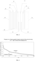
- FIG. 3 shows change curves of electric potentials of negative electrodes of three-electrode cell structures in Example 1 and Comparative Example 1 of the present invention during charging at a constant current of 1 C at 25°C.
- An abscissa is a battery charging state (soc/%), which is 0.00%, 20.00%, 40.00%, 60.00%, 80.00% and 100.00% sequentially, and an ordinate is an electric potential of the negative electrode (V), which is -0.05, 0.00, 0.05, 0.10, 0.15, 0.20, 0.25, 0.30 and 0.35 sequentially.
Landscapes
- Engineering & Computer Science (AREA)
- Chemical & Material Sciences (AREA)
- Manufacturing & Machinery (AREA)
- Chemical Kinetics & Catalysis (AREA)
- Electrochemistry (AREA)
- General Chemical & Material Sciences (AREA)
- Physics & Mathematics (AREA)
- General Physics & Mathematics (AREA)
- Materials Engineering (AREA)
- Secondary Cells (AREA)
Abstract
Description
- The present invention relates to the field of batteries, in particular to a three-electrode cell structure and a preparation method therefor, and a method for testing an electric potential of a negative electrode.
- Lithium batteries, as a power source for electronic products, are widely used and essential in social life. The increasing consumption of fossil energy on Earth and the resulted environmental issues have also sounded an alarm for human energy applications. On the one hand, it is necessary to develop and utilize renewable energy to reduce dependence on single fossil energy, and on the other hand, it is necessary to control and harmlessly treat harmful substances generated by the consumption of the fossil energy. In response to these issues, replacing existing fossil energy with electric energy for driving vehicles, namely developing power battery vehicles, has become one of the efforts of various countries.
- However, during the use of lithium batteries, a lithium precipitation phenomenon is prone to occurring in negative electrodes, the generation of lithium precipitation will accelerate the capacity degradation of the batteries, in severe cases, it will puncture separator membranes, causing internal short circuits, and resulting in serious safety accidents. Therefore, how to accurately judge whether lithium precipitation occurs in lithium battery cells is very important.
- At present, methods for judging lithium precipitation of the cells include: 1, a three-electrode method, taking an electric potential of a negative electrode of 0 V as a standard for negative electrode lithium precipitation; 2, a voltage relaxation curve method, taking whether there is a characteristic peak in a voltage curve in a standing state after charging as a judging standard for lithium precipitation; 3, a discharge capacity differential curve method, judging whether lithium precipitation occurs by observing whether there is a characteristic peak in a capacity differential curve in a discharging process; and 4, a visual method, mainly, disassembling the cells in a cycling process in a fully charged state, observing a negative electrode interface and judging whether lithium precipitation occurs.
- However, in the current testing methods, the voltage relaxation curve and discharge capacity differential curve methods have obvious characteristic peaks when lithium precipitation occurs at a low temperature in the cells, but the characteristic peaks are difficult to observe at a room temperature, such that there are certain limitations. The visual method requires a long-time cycling test to judge whether lithium precipitation occurs through cycling disassembly, the time consumption is long, and costs are high. Moreover, the method for judging whether lithium precipitation occurs by disassembling a battery to observe a negative electrode interface is affected by human influence greatly due to the limitations of human visual observation, which will result in errors in the judgment of results and cannot be quantified through specific data. A relatively mature method is to judge whether lithium precipitation occurs through a three-electrode cell, with the electric potential of the negative electrode of 0 V as a standard. When the electric potential of the negative electrode is less than 0 V, it is considered that lithium precipitation occurs. However, in an actual production process of the three-electrode cell, it is necessary to add a separator membrane outside a reference electrode, the separator membrane is introduced into the production process to generate polarization, which will cause a certain deviation in test results of three electrodes, and correction is required.
- In summary, in the prior art, when the three-electrode method is used to test the electric potential of the negative electrode, there is a deviation due to the introduction of the separator membrane, which results in inaccurate test results. Therefore, it is necessary to provide a testing method that can eliminate the polarization generated by the introduction of the separator membrane in a three electrode production process to a maximum extent, so that the deviation is effectively removed, and real potential on a surface of a negative electrode is obtained.
- A main objective of the present invention is to provide a three-electrode cell structure and a preparation method therefor, and a method for testing an electric potential of a negative electrode, so as to solve the problem of inaccurate test results caused by polarization generated by the introduction of a separator membrane when using a three-electrode method to test the electric potential of the negative electrode in the prior art.
- In order to achieve the above objective, according to one aspect of the present invention, a three-electrode cell structure is provided, including a shell, an electrolyte solution encapsulated inside the shell, and at least one electrode group, the electrode group includes a positive electrode, a negative electrode and a first separator membrane located between the positive electrode and the negative electrode, and the at least one electrode group further includes a first reference electrode, located between the negative electrode and the first separator membrane; a second separator membrane, located between the negative electrode and the first reference electrode; a second reference electrode, located between the positive electrode and the first separator membrane; and a third separator membrane, located between the positive electrode and the second reference electrode. The first separator membrane, the second separator membrane and the third separator membrane all have the same structure.
- Further, the first reference electrode and the second reference electrode are both copper wires; preferably, each of the copper wires has a first end head and a second end head opposite to the first end head, wherein the first end head is a bare copper wire end head and located between the positive electrode and the negative electrode; and the second end head is an enamelled copper wire end head and located outside the space between the positive electrode and the negative electrode, and the second end head penetrates through the shell to extend to the outside of the shell.
- Further, the first end head has a length ranging from 1 cm to 2.5 cm; and preferably, the enamelled copper wire end head has a diameter ranging from 22 µm to 53 µm, and the bare copper wire end head has a diameter ranging from 20 µm to 50 µm.
- Further, a metal lithium layer is plated on a surface of the first end head.
- Further, when the three-electrode cell structure includes a plurality of electrode groups, the plurality of electrode groups are sequentially connected in parallel, every two adjacent electrode groups are separated by a fourth separator membrane, and the fourth separator membrane has the same structure as the first separator membrane.
- In order to achieve the above objective, according to one aspect of the present invention, a preparation method for the above three-electrode cell structure is provided, including the following steps:
step S 1, providing at least one electrode group, wherein each electrode group includes a positive electrode, a negative electrode and a first separator membrane located between the positive electrode and the negative electrode, and the at least one electrode group further includes a first reference electrode disposed between the negative electrode and the first separator membrane; a second separator membrane disposed between the negative electrode and the first reference electrode; a second reference electrode disposed between the positive electrode and the first separator membrane; and a third separator membrane disposed between the positive electrode and the second reference electrode, wherein the first separator membrane, the second separator membrane and the third separator membrane all have the same structure; and step S2, encapsulating the at least one electrode group by a shell, and filling the shell with an electrolyte solution to obtain the three-electrode cell structure. - Further, in step S1, a process of disposing the first reference electrode and the second reference electrode is as follows: putting one end of an enamelled copper wire into concentrated sulfuric acid to remove an enamelled coating on a surface, then washing with water to obtain a copper wire with a first end head as a bare copper wire end head and a second end head as an enamelled copper wire end head; putting the first end head of one copper wire prepared by the above step between the negative electrode and the first separator membrane, and putting the second end head thereof outside the space between the negative electrode and the first separator membrane to form the first reference electrode; putting the first end head of another copper wire prepared by the above step between the positive electrode and the first separator membrane, and putting the second end head thereof outside the space between the positive electrode and the first separator membrane to form the second reference electrode; and arranging, after encapsulation, the second end heads of the first reference electrode and the second reference electrode to both penetrate through the shell to extend to the outside of the shell.
- Further, after the step of filling the shell with the electrolyte solution, the step S2 further includes a step of plating lithium on a surface of the bare copper wire end head; preferably, lithium plating treatment is performed on the surfaces of the bare copper wire end heads of the first reference electrode and the second reference electrode respectively at a current ranging from 10 mA to 15 mA by using an external power supply; and preferably, a lithium plating treatment process is performed for treatment time ranging from 6h to 8h.
- According to another aspect of the present invention, a method for testing an electric potential of a negative electrode is provided. The method includes the following steps: providing a three-electrode cell, the three-electrode cell being of the above three-electrode cell structure or a three-electrode cell structure prepared by the above preparation method, wherein a negative electrode in the three-electrode cell is a to-be-tested negative electrode; charging the three-electrode cell, and in the charging process, recording an electric potential change of a first reference electrode relative to the negative electrode as ϕ1, recording an electric potential change of a second reference electrode relative to the negative electrode as ϕ2, designating a potential value of the negative electrode as ϕnegative electrode, and designating a polarization value caused by a separator membrane as Δϕseparator membrane; and calculating the potential value of the negative electrode by using the following formula I and formula II: Δϕseparator membrane=ϕ2-ϕ1, and ϕnegative electrode=ϕ1-Δϕseparator membrane.
- Further, the charging process is performed at a temperature ranging from -45°C to 60°C.
- In the three-electrode cell structure of the present invention, the second separator membrane, the first reference electrode, the first separator membrane, the second reference electrode and the third separator membrane are sequentially disposed between the negative electrode and the positive electrode of the at least one electrode group in a stacked mode. In an actual measurement process, assembly is performed according to the three-electrode cell structure provided in the present invention in a production process of laminating and winding cells; then, polarization generated by the introduction of the separator membrane in testing the three electrodes can be corrected by testing a potential difference between the negative electrode and the first reference electrode, and a potential difference between the negative electrode and the second reference electrode, so that a deviation is effectively removed; and a more accurate electric potential of the negative electrode is attained by measuring in a charging process, thereby providing more accurate data support for judging whether lithium precipitation occurs in a lithium battery.
- Accompanying drawings of the specification, which constitute a part of the present application, are used to provide a further understanding of the present invention, and the schematic examples of the present invention and descriptions thereof are used to explain the present invention, and do not constitute an improper limitation to the present invention. In the figures:
-
FIG. 1 shows a schematic diagram of a three-electrode cell structure in an implementation of the present invention. -
FIG. 2 shows a schematic diagram of a three-electrode cell structure in another implementation of the present invention. -
FIG. 3 shows a test diagram of an electric potential of a negative electrode of a three-electrode cell structure in Example 1 and Comparative Example 1 of the present invention. -
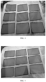
FIG. 4 shows a photo of a negative electrode interface of battery disassembly after fully charging in Example 1 of the present invention. -
FIG. 5 shows a photo of a negative electrode interface of battery disassembly after fully charging in Comparative Example 1 of the present invention. - The above accompanying drawings include the following reference numerals:
10, electrode group; 11, positive electrode; 12, negative electrode; 13, first separator membrane; 14, first reference electrode; 15, second separator membrane; 16, second reference electrode; 17, third separator membrane; and 18, fourth separator membrane. - It should be noted that the examples and features in the examples of the present application may be combined with each other in the case of not conflict. The present invention will be described in detail below with reference to the accompanying drawings and in combination with the examples.
- As described in the background part, in the prior art, when a three-electrode method is used to test electric potential of a negative electrode, polarization is generated by the introduction of a separator membrane, resulting in inaccurate test results. In order to solve the problem, the present invention provides a three-electrode cell structure, including a shell, an electrolyte solution encapsulated inside the shell, and at least one electrode group, the electrode group includes a
positive electrode 11, anegative electrode 12 and afirst separator membrane 13 located between thepositive electrode 11 and thenegative electrode 12, and the at least one electrode group further includes afirst reference electrode 14, located between thenegative electrode 12 and thefirst separator membrane 13; asecond separator membrane 15, located between thenegative electrode 12 and thefirst reference electrode 14; asecond reference electrode 16, located between thepositive electrode 11 and thefirst separator membrane 13; and athird separator membrane 17, located between thepositive electrode 11 and thesecond reference electrode 16. Thefirst separator membrane 13, thesecond separator membrane 15 and thethird separator membrane 17 all have the same structure. - In the three-electrode cell structure of the present invention, in the at least one electrode group, the
first separator membrane 13, thefirst reference electrode 14, thesecond separator membrane 15, thesecond reference electrode 16 and thethird separator membrane 17 are sequentially disposed between thenegative electrode 12 and thepositive electrode 11 in a stacked mode. Different from a traditional three-electrode cell, the three-electrode cell structure of the present invention introduces thefirst reference electrode 14, thesecond separator membrane 15, thesecond reference electrode 16 and thethird separator membrane 17 into the at least one electrode group. As shown inFIG. 1 andFIG. 2 , thefirst reference electrode 14 is located between thenegative electrode 12 and thefirst separator membrane 13, thesecond separator membrane 15 is located between thenegative electrode 12 and thefirst reference electrode 14, thesecond reference electrode 16 is located between thepositive electrode 11 and thefirst separator membrane 13, thethird separator membrane 17 is located between thepositive electrode 11 and thesecond reference electrode 16, and thefirst separator membrane 13, thesecond separator membrane 15 and thethird separator membrane 17 all have the same structure. - In an actual measurement process, assembly is performed according to the three-electrode cell structure provided in the present invention in a production process of laminating and winding cells, then, a polarization difference value generated by the introduction of the separator membrane in testing the three electrodes can be corrected by testing a potential difference between the negative electrode and the
first reference electrode 14, and a potential difference between the negative electrode and thesecond reference electrode 16, so that a deviation is effectively removed; and a more accurate electric potential of the negative electrode is attained by measuring in a charging process, thereby providing more accurate data support for judging whether lithium precipitation occurs in a battery. Specifically, in a subsequent testing process, the above three-electrode cell is charged, and in the charging process, an electric potential change of thefirst reference electrode 14 relative to the negative electrode is recorded as ϕ1, an electric potential change of thesecond reference electrode 16 relative to the negative electrode is recorded as ϕ2, a potential value of the negative electrode is designated as ϕnegative electrode, and a polarization value caused by the separator membrane is designated as Δϕseparator membrane; and through the following calculation formulas. Δϕseparator membrane=ϕ2-ϕ1, and ϕnegative electrode=ϕ1-Δϕseparator membrane, the polarization value caused by the separator membrane Δϕseparator membrane may be calculated, the deviation caused by the separator membrane is effectively removed, so as to obtain the more accurate electric potential of the negative electrode and provide more accurate data support for judging whether lithium precipitation occurs in the battery. - In the above three-electrode cell structure, in addition to the to-be-tested negative electrode, other separator membranes, positive electrodes and electrolyte solutions may all adopt commonly used types in the field of lithium batteries or a testing process of the three-electrode method. In a preferred embodiment, in the above three-electrode cell structure, the
first separator membrane 13, thesecond separator membrane 15 and thethird separator membrane 17 are each independently one of a porous polymer separator membrane, a non-woven fabric separator membrane or an inorganic composite separator membrane. The separator membranes may be purchased from separator membrane material companies such as Enjie, Xingyuan, Cangzhou Mingzhu and ZTE New Materials. The shell may be made of an aluminum plastic film, and may be a cylindrical or square shell specifically; and the electrolyte solution includes, but is not limited to one of organic solvent electrolyte lithium salts. In a preferred embodiment, thepositive electrode 11 is made of lithium cobalt oxide LCO, a nickel-cobalt-manganese ternary material NCM or lithium iron phosphate LFP, and preferably, the positive electrode material has a length ranging from 5 cm to 30 cm, a width ranging from 3 cm to 20 cm, and a thickness ranging from 0.1 cm to 0.2 cm; and preferably, a negative electrode material is a carbon negative electrode material, a silicon negative electrode material or a lithium-containing transition metal nitride negative electrode material, and preferably, the negative electrode material has a length ranging from 5.5 cm to 30.5 cm, a width ranging from 3.5 cm to 20.5 cm, and a thickness ranging from 0.1 cm to 0.2 cm. The three-electrode cell structure may be obtained by encapsulating the above electrode group, shell and electrolyte solution according to a production process of a soft package cell or a square shell cell. These are all options that those skilled in the art can choose based on their own production needs, and will not be repeated here. - Preferably, the
first reference electrode 14 and thesecond reference electrode 16 are both copper wires; preferably, each of the copper wires has a first end head and a second end head opposite to the first end head, wherein the first end head is a bare copper wire end head and located between thepositive electrode 11 and thenegative electrode 12; and the second end head is an enamelled copper wire end head and located outside the space between thepositive electrode 11 and thenegative electrode 12, and the second end head penetrates through the shell to extend to the outside of the shell. The copper wires are taken as thefirst reference electrode 14 and thesecond reference electrode 16, on the one hand, they are easy to obtain and have low costs. On the other hand, transmission efficiency of lithium ions between the positive electrode and the negative electrode may be improved, and potential of thepositive electrode 11 and potential of thenegative electrode 12 may be monitored in situ in a charging process of a lithium-ion battery. In addition, one ends of the reference electrodes are the copper wires, and the other ends of the reference electrodes are enamelled copper wires, in this way, interference of the electrolyte solution on electrical signals may be reduced to a larger extent, and thus detection accuracy is improved. Furthermore, it is inevitable that copper wires between the two end heads are immersed in the electrolyte solution in an encapsulation process, and in order to further reduce the interference of the electrolyte solution on the electrical signals, it is preferred to use the enamelled copper wires as copper wires in a middle section between the first end head and the second end head. In an actual assembly process, a whole copper wire may be used as thefirst reference electrode 14, another whole copper wire may be used as thesecond reference electrode 16, then first end heads of the copper wires are disposed as bare copper wire end heads, and the remaining parts, including the middle section and second end heads, are disposed as the enamelled copper wires. - In order to further improve stability of the setting of the
first reference electrode 14 and thesecond reference electrode 16 and maintain the stability of currents in the electrode group, so as to further improve the detection accuracy, preferably, the first end head has a length ranging from 1 cm to 2.5 cm; and preferably, the enamelled copper wire end head has a diameter ranging from 22 µm to 53 µm, and the bare copper wire end head has a diameter ranging from 20 µm to 50 µm. - Preferably, a metal lithium layer is plated on a surface of the first end head. In this way, the potential stability of the reference electrodes may be further improved, thereby promoting the detection accuracy to be higher.
- For the three-electrode cell structure of the present invention, on the one hand, capacity demands of a conventional battery may be met, and on the other hand, the electric potential of the negative electrode in a charging and discharging process of the battery itself may further be tested. Preferably, in an embodiment, conventional battery production is simulated, when the three-electrode cell structure includes a plurality of electrode groups, as shown in
FIG. 2 , the plurality ofelectrode groups 10 are sequentially disposed in parallel, every twoadjacent electrode groups 10 are separated through afourth separator membrane 18, and thefourth separator membrane 18 has the same structure as thefirst separator membrane 13. This may be operated according to the well-known battery preparation process in the art, which may be self-assembled by those skilled in the art according to production needs. For example, parallel setting refers to thenegative electrode 12 of the second electrode group being close to thepositive electrode 11 of the first electrode group, and the two are separated by thefourth separator membrane 18, which will not be repeated here. - The present invention further provides a preparation method for the above three-electrode cell structure. The preparation method includes the following steps: step S1, at least one electrode group is provided, wherein each electrode group includes a
positive electrode 11, anegative electrode 12 and afirst separator membrane 13 located between thepositive electrode 11 and thenegative electrode 12, and the at least one electrode group further includes: afirst reference electrode 14 disposed between thenegative electrode 12 and thefirst separator membrane 13; asecond separator membrane 15 disposed between thenegative electrode 12 and thefirst reference electrode 14; asecond reference electrode 16 disposed between thepositive electrode 11 and thefirst separator membrane 13; and athird separator membrane 17 disposed between thepositive electrode 11 and thesecond reference electrode 16, wherein thefirst separator membrane 13, thesecond separator membrane 15 and thethird separator membrane 17 all have the same structure; and step S2, the at least one electrode group is encapsulated in a shell, and the shell is filled with an electrolyte solution to obtain the three-electrode cell structure. - Based on the various reasons mentioned earlier, the three-electrode cell structure of the present disclosure introduces the
first reference electrode 14, thesecond separator membrane 15, thesecond reference electrode 16 and thethird separator membrane 17 into the at least one electrode group. Thefirst reference electrode 14 is located between thenegative electrode 12 and thefirst separator membrane 13, thesecond separator membrane 15 is located between thenegative electrode 12 and thefirst reference electrode 14, thesecond reference electrode 16 is located between thepositive electrode 11 and thefirst separator membrane 13, thethird separator membrane 17 is located between thepositive electrode 11 and thesecond reference electrode 16, and thefirst separator membrane 13, thesecond separator membrane 15 and thethird separator membrane 17 all have the same structure. Specifically, in a cell production and manufacturing process, assembly is performed according to the three-electrode cell structure provided in the present invention, then, a polarization difference value generated by the introduction of the separator membrane in testing the three electrodes can be corrected by testing a potential difference between the negative electrode and thefirst reference electrode 14, and a potential difference between the negative electrode and thesecond reference electrode 16, so that a deviation is effectively removed; and a more accurate electric potential of the negative electrode is attained by measuring in a charging process, thereby providing more accurate data support for judging whether lithium precipitation occurs in a battery. Specifically, in a subsequent testing process, the above three-electrode cell is charged, in a charging process, an electric potential change of thefirst reference electrode 14 relative to the negative electrode is recorded as ϕ1, an electric potential change of thesecond reference electrode 16 relative to the negative electrode is recorded as ϕ2, a potential value of the negative electrode is designated as ϕnegative electrode, and a polarization value caused by the separator membrane is designated as Δϕseparator membrane; and through the following calculation formulas: Δϕseparator membrane=ϕ2-ϕ1, and ϕnegative electrode=ϕ1-Δϕseparator membrane, the polarization value caused by the separator membrane Δϕseparator membrane may be calculated, the deviation caused by the separator membrane is effectively removed, so as to obtain the more accurate electric potential of the negative electrode and provide more accurate data support for judging whether lithium precipitation occurs in the battery. - Preferably, in step S1, a process of disposing the
first reference electrode 14 and thesecond reference electrode 16 is as follows: one end of an enamelled copper wire is put into concentrated sulfuric acid with a concentration of 98% to remove an enamelled coating on a surface thereof, then it is washed with water to obtain a copper wire with a first end head as a bare copper wire end head and a second end head as an enamelled copper wire end head; the first end head of one copper wire is put between thenegative electrode 12 and thefirst separator membrane 13, and the second end head is put outside thenegative electrode 12 and thefirst separator membrane 13; the first end head of the other copper wire is put between thepositive electrode 11 and thefirst separator membrane 13, and the second end head is put outside the space between thepositive electrode 11 and thefirst separator membrane 13; and after the encapsulation step, thefirst reference electrode 14 and thesecond reference electrode 16 are formed. In this way, the outer enamelled part of the first end head may be completely removed to obtain a bare copper wire with a higher purity, thereby improving the transmission efficiency of the lithium ions between the positive electrode and the negative electrode. Preferably, washing treatment may further remove the residual concentrated sulfuric acid on the surface of the bare copper wire at the first end head. - Preferably, after the step of filling the shell with the electrolyte solution, the step S2 further includes a step of plating lithium on a surface of the bare copper wire end head; preferably, lithium plating treatment is performed on the
first reference electrode 14 and thesecond reference electrode 16 respectively by using a current ranging from 10 mA to 15 mA; and preferably, a lithium plating treatment process is performed for treatment time ranging from 6h to 8h. In this way, the lithium plating process is more stable, the effects of detecting internal chemical and electrochemical reactions in the battery may be further balanced, and thus the detection accuracy is improved. In an actual operation process, an external power supply is provided, firstly, a positive electrode of the power supply is connected with thepositive electrode 11 in the three-electrode cell structure of the present invention, a negative electrode of the power supply is connected with the reference electrodes in the three-electrode cell structure of the present invention, after treating with the current ranging from 10 mA to 15 mA for 3h, the positive electrode of the power supply is connected with the negative electrode in the three-electrode cell structure of the present invention, the negative electrode of the power supply is connected with the reference electrodes in the three-electrode cell structure of the present invention, and similarly after treating with the current ranging from 10 mA to 15 mA for 3h, the reference electrodes with metal lithium layers plated on the surfaces of the first end heads are obtained. This is an operation that may be performed by those skilled in the art in conjunction with conventional knowledge, which will not be repeated here. - The present invention further provides a method for testing an electric potential of a negative electrode, including the following steps: a three-electrode cell is provided, the three-electrode cell being the above three-electrode cell or a three-electrode cell prepared by the above preparation method, wherein a negative electrode in the three-electrode cell is a to-be-tested
negative electrode 12; the three-electrode cell is charged, in a charging process, an electric potential change of afirst reference electrode 14 relative to thenegative electrode 12 is recorded as ϕ1, an electric potential change of asecond reference electrode 16 relative to thenegative electrode 12 is recorded as ϕ2, a potential value of thenegative electrode 12 is designated as ϕnegative electrode, and a polarization value caused by a separator membrane is designated as Δϕseparator membrane; and the potential on the surface of thenegative electrode 12 is calculated, wherein calculation formulas are as follows: Δϕseparator membrane=ϕ2-ϕ1, and ϕnegative electrode=ϕ1-Δϕseparator membrane. - Based on the various reasons mentioned earlier, in an actual measurement process, assembly is performed according to the three-electrode cell structure provided in the present invention, then, a polarization difference value generated by the introduction of the separator membrane in testing the three electrodes can be corrected by testing a potential difference between the negative electrode and the
first reference electrode 14, and a potential difference between the negative electrode and thesecond reference electrode 16, so that a deviation is effectively removed; and a more accurate electric potential of the negative electrode is attained by measuring in a charging process, thereby providing more accurate data support for judging whether lithium precipitation occurs in a battery. Specifically, in a subsequent testing process, the above three-electrode cell is charged, in a charging process, an electric potential change of thefirst reference electrode 14 relative to the negative electrode is recorded asφ 1, an electric potential change of thesecond reference electrode 16 relative to the negative electrode is recorded as ϕ2, a potential value of the negative electrode is designated as ϕnegative electrode, and a polarization value caused by the separator membrane is designated as Δϕseparator membrane; and through the following calculation formulas: Δϕseparator membrane=ϕ2-ϕ1, and ϕnegative electrode=ϕ1-Δϕseparator membrane, the polarization value Δϕseparator membrane caused by the separator membrane separator membrane may be calculated, the deviation caused by the separator membrane is effectively removed, so as to obtain the more accurate electric potential of the negative electrode and provide more accurate data support for judging whether lithium precipitation occurs in the battery. - In order to further promote the stability of the charging process to be better, so as to improve the detection accuracy, preferably, the charging process is performed at a temperature ranging from -45°C to 60°C.
- The present application is further described in details in conjunction with specific examples below, and these examples cannot be understood as limiting the scope of protection claimed in the present application.
- Negative electrode sheet source: 5 Ah soft package cell graphite negative electrode. A negative electrode material is Gr graphite, with a length of 105 mm, a width of 55 mm and a thickness of 0.1 mm.
- Positive electrode sheet source: 5 Ah soft package cell NCM ternary positive electrode. A positive electrode material is an NCM ternary positive electrode, with a length of 100 mm, a width of 50 mm and a thickness of 0.1 mm.
- A separator membrane is purchased from a porous polymer separator membrane of ZTE New Materials Technology Co., Ltd.
- A three-electrode cell structure is as shown in
FIG. 1 , and a process for preparing the three-electrode cell structure is as follows. - 1. One ends of 2 cm with a diameter of 20 mm of two enamelled copper wires are put into concentrated sulfuric acid respectively to remove enamelled coatings on surfaces, and then they are washed with water to obtain two copper wires with first end heads as bare copper wire end heads and second end heads as enamelled copper wire end heads, which are a first reference electrode and a second reference electrode respectively.
- 2. A second separator membrane, the first reference electrode, a first separator membrane, the second reference electrode, a third separator membrane and a positive electrode sheet are sequentially disposed on a negative electrode sheet to obtain an electrode group, wherein the first end head of the first reference electrode is put between the negative electrode and the first separator membrane, and the second end head is put outside the negative electrode and the first separator membrane; and the first end head of the second reference electrode is put between the positive electrode and the first separator membrane, and the second end head is put outside the space between the positive electrode and the first separator membrane.
- 3. Parts of the second end heads of the first reference electrode and the second reference electrode are guided out of a cell shell, and a nickel belt is welded to the second end heads.
- 4. The above electrode group, shell and an electrode solution are encapsulated according to a production process of a soft package cell or a square shell cell.
- 5. After encapsulation, lithium plating is performed on the first reference electrode and the second reference electrode respectively by using a current of 10 mA, and metal lithium layers are both formed at the first end heads of the two to obtain the three-electrode cell structure.
- 6. The above three-electrode cell structure is charged at a 1C rate at a temperature ranging from -40°C to -30°C, and meanwhile electric potential changes of the first reference electrode and the second reference electrode relative to the negative electrode are monitored.
- 7. In a charging process, the electric potential change of the first reference electrode relative to the negative electrode is recorded as
cp 1, the electric potential change of the second reference electrode relative to thenegative electrode 12 is recorded as cp2, a potential value of the negative electrode is designated as ϕnegative electrode, and a polarization value caused by the separator membrane is designated as Δϕseparator membrane; and potential on the surface of the negative electrode is calculated through Δϕseparator membrane=ϕ2-ϕ1 and ϕnegative electrode=ϕ1-Δϕseparator membrane. - The difference from Example 1 is only that the three-electrode cell structure includes two electrode groups, and the three-electrode cell structure is as shown in
FIG. 2 . - The difference from Example 1 is only that there is no second separator membrane and second reference electrode. The electric potential change of the first reference electrode relative to the negative electrode is the potential on the surface of the negative electrode.
- The cells in Example 1 and Comparative Example 1 are put into a constant temperature and humidity box (Sanmu Technology brand, with a temperature control range from -70°C to 180°C, and a humidity range from 10% to 98%), and the cells are subject to charging and discharging cycling through a 5 V, 6 A Xinwei charging and discharging device. Charging is performed at a constant current of 1 C to a charge cutoff voltage and then performed at a constant voltage, charging is stopped until a charge end current drops to 0.05 C, it is subject to standing for 0.5h after charging, and then discharging is performed at 1 C to a discharge end voltage. This system is performed for 2000 cycles until a discharge capacity is 80% of an initial capacity, and after cycling, the cells are charged fully (soc100%).
- The fully charged cells are disassembled, their negative electrode interfaces are observed, no lithium precipitation is observed on surfaces of negative electrode sheets tested in Examples and Comparative Example, that is, lithium precipitation does not occur in the tested cells in Example 1 and Comparative Example 1 under an environmental temperature of 25°C and 1 C cycling conditions, as shown in
FIG. 4 (Example 1) andFIG. 5 (Comparative Example 1). As shown inFIG. 3 , in Example 1, the corrected potential on the surface of the negative electrode after charging 100% is a positive value, indicating that test results in Example 1 of the present invention are consistent with actual situations. But in Comparative Example 1, the potential on the surface of the negative electrode after charging 100% is a negative value, which is not consistent with the actual situations. Whether lithium precipitation occurs is judged through a three-electrode cell, with the electric potential of the negative electrode of 0 V as a standard. When the electric potential of the negative electrode is less than 0 V, it is considered that lithium precipitation occurs. However, in an actual production process of the three-electrode cell, it is necessary to add a separator membrane outside a reference electrode, the separator membrane is introduced into the production process to generate polarization, which will cause a certain deviation in test results of three electrodes. The polarization value caused by the separator membrane cannot be tested in Comparative Example 1, so its test results are inaccurate. In the present invention, the polarization value caused by the separator membrane may be tested, so that an actual potential value on the surface of the negative electrode may be obtained by correcting, and the test results are more accurate. -
FIG. 3 shows change curves of electric potentials of negative electrodes of three-electrode cell structures in Example 1 and Comparative Example 1 of the present invention during charging at a constant current of 1 C at 25°C. An abscissa is a battery charging state (soc/%), which is 0.00%, 20.00%, 40.00%, 60.00%, 80.00% and 100.00% sequentially, and an ordinate is an electric potential of the negative electrode (V), which is -0.05, 0.00, 0.05, 0.10, 0.15, 0.20, 0.25, 0.30 and 0.35 sequentially. - The above is only preferred examples of the present invention and is not intended to limit the present invention. For those skilled in the art, the present invention may have various modifications and variations. Any modification, equivalent replacement, improvement, etc. made within the spirit and principle of the present invention should be included in the protection scope of the present invention.
Claims (10)
- A three-electrode cell structure, comprising a shell, an electrolyte solution encapsulated inside the shell, and at least one electrode group (10), wherein the electrode group comprises a positive electrode (11), a negative electrode (12) and a first separator membrane located between the positive electrode (11) and the negative electrode (12), characterized in that the at least one electrode group further comprises:a first reference electrode (14), located between the negative electrode (12) and the first separator membrane (13);a second separator membrane (15), located between the negative electrode (12) and the first reference electrode (14);a second reference electrode (16), located between the positive electrode (11) and the first separator membrane (13); anda third separator membrane (17), located between the positive electrode (11) and the second reference electrode (16);wherein, the first separator membrane (13), the second separator membrane (15) and the third separator membrane (17) all have the same structure.
- The three-electrode cell structure of claim 1, characterized in that the first reference electrode (14) and the second reference electrode (16) are both copper wires.
- The three-electrode cell structure of claim 2, characterized in that each of the copper wires has a first end head and a second end head opposite to the first end head, wherein the first end head is a bare copper wire end head and located between the positive electrode (11) and the negative electrode (12); and the second end head is an enamelled copper wire end head and located outside the space between the positive electrode (11) and the negative electrode (12), and the second end head penetrates through the shell to extend to the outside of the shell, and the first end head has a length ranging from 1 cm to 2.5 cm.
- The three-electrode cell structure of claim 3, characterized in that a metal lithium layer is plated on a surface of the first end head.
- The three-electrode cell structure of any one of claims 1 to 3, characterized in that, when the three-electrode cell structure comprises a plurality of electrode groups, the plurality of electrode groups are sequentially connected in parallel, every two adjacent electrode groups are separated by a fourth separator membrane (18), and the fourth separator membrane (18) has the same structure as the first separator membrane (13).
- A preparation method for the three-electrode cell structure of any one of claims 1 to 5, characterized by comprising the following steps:step S1, providing at least one electrode group, wherein each electrode group comprises a positive electrode (11), a negative electrode (12) and a first separator membrane (13) located between the positive electrode (11) and the negative electrode (12), and the at least one electrode group further comprises:a first reference electrode (14) disposed between the negative electrode (12) and the first separator membrane (13);a second separator membrane (15) disposed between the negative electrode (12) and the first reference electrode (14);a second reference electrode (16) disposed between the positive electrode (13) and the first separator membrane (13); anda third separator membrane (17) disposed between the positive electrode (11) and the second reference electrode (16);wherein, the first separator membrane (13), the second separator membrane (15) and the third separator membrane (17) all have the same structure; andstep S2, encapsulating the at least one electrode group by a shell, and filling the shell with an electrolyte solution to obtain the three-electrode cell structure.
- The preparation method of claim 6, characterized in that, in step S1, the process of disposing the first reference electrode (14) and the second reference electrode (16) is as follows:putting one end of an enamelled copper wire into concentrated sulfuric acid with a mass concentration of 98% to remove an enamelled coating on a surface thereof, then washing with water to obtain a copper wire with a first end head as a bare copper wire end head and a second end head as an enamelled copper wire end head;putting the first end head of one copper wire prepared by the above step between the negative electrode (12) and the first separator membrane (13), and putting the second end head thereof outside the space between the negative electrode (12) and the first separator membrane (13) to form the first reference electrode (14);putting the first end head of another copper wire prepared by the above step between the positive electrode (11) and the first separator membrane (13), and putting the second end head thereof outside the space between the positive electrode (11) and the first separator membrane (13) to form the second reference electrode (16); andarranging, after encapsulation, the second end heads of the first reference electrode (14) and the second reference electrode (16) to both penetrate through the shell to extend to the outside of the shell.
- The preparation method of claim 7, characterized in that after the step of filling the shell with the electrolyte solution, the step S2 further comprises a step of performing lithium plating on a surface of the bare copper wire end head.
- A method for testing an electric potential of a negative electrode, characterized by comprising the following steps:providing a three-electrode cell, the three-electrode cell being of the three-electrode cell structure of any one of claims 1 to 5 or a three-electrode cell structure prepared by the preparation method of any one of claims 6 to 8, wherein a negative electrode in the three-electrode cell is a to-be-tested negative electrode (12);charging the three-electrode cell, and in the charging process, recording an electric potential change of the first reference electrode (14) relative to the negative electrode (12) as ϕ1, recording an electric potential change of the second reference electrode (16) relative to the negative electrode (12) as ϕ2, designating an electric potential value of the negative electrode as ϕnegative electrode, and designating a polarization value caused by a separator membrane as Δϕseparator membrane; and calculating the electric potential value of the negative electrode by using the following formula I and formula II:


- The method of claim 9 for testing an electric potential of a negative electrode, characterized in that the charging process is performed at a temperature ranging from -45°C to 60°C.
Applications Claiming Priority (2)
| Application Number | Priority Date | Filing Date | Title |
|---|---|---|---|
| CN202110640079.4A CN113258156B (en) | 2021-06-09 | 2021-06-09 | Three-electrode cell structure, preparation method thereof and method for testing negative electrode potential |
| PCT/CN2022/083838 WO2022257566A1 (en) | 2021-06-09 | 2022-03-29 | Three-electrode cell structure and preparation method therefor, and method for testing negative electrode potential |
Publications (2)
| Publication Number | Publication Date |
|---|---|
| EP4322282A1 true EP4322282A1 (en) | 2024-02-14 |
| EP4322282A4 EP4322282A4 (en) | 2024-09-11 |
Family
ID=77187131
Family Applications (1)
| Application Number | Title | Priority Date | Filing Date |
|---|---|---|---|
| EP22819171.4A Pending EP4322282A4 (en) | 2021-06-09 | 2022-03-29 | THREE-ELECTRODE CELLULAR STRUCTURE AND PREPARATION METHOD THEREOF, AND NEGATIVE ELECTRODE POTENTIAL TESTING METHOD |
Country Status (3)
| Country | Link |
|---|---|
| EP (1) | EP4322282A4 (en) |
| CN (1) | CN113258156B (en) |
| WO (1) | WO2022257566A1 (en) |
Families Citing this family (11)
| Publication number | Priority date | Publication date | Assignee | Title |
|---|---|---|---|---|
| CN113258156B (en) * | 2021-06-09 | 2021-11-30 | 蜂巢能源科技有限公司 | Three-electrode cell structure, preparation method thereof and method for testing negative electrode potential |
| CN113933361A (en) * | 2021-12-17 | 2022-01-14 | 苏州易来科得科技有限公司 | Electrochemical device with reference electrode and lithium precipitation prevention application method thereof |
| CN113937340B (en) * | 2021-12-17 | 2022-03-08 | 中创新航科技股份有限公司 | Cell, battery and charging method |
| CN115963419B (en) * | 2023-01-16 | 2026-04-21 | 同济大学 | A fabrication and testing method for modifying a three-electrode battery based on a commercial battery. |
| CN115863785B (en) * | 2023-02-09 | 2023-04-28 | 楚能新能源股份有限公司 | Lithium ion battery and method for monitoring lithium deposition |
| CN116207357B (en) * | 2023-03-10 | 2024-12-06 | 国联汽车动力电池研究院有限责任公司 | Three-electrode cell structure, three-electrode battery and negative electrode potential monitoring method |
| CN116641074A (en) * | 2023-04-17 | 2023-08-25 | 合肥工业大学 | A battery positive electrode material regeneration device and method based on electrochemical reaction |
| CN116577659B (en) * | 2023-06-26 | 2025-12-30 | 湖北亿纬动力有限公司 | Battery testing methods |
| CN117491449A (en) * | 2023-11-07 | 2024-02-02 | 深蓝汽车科技有限公司 | Reference electrode assembly and preparation method and application thereof |
| CN118588457A (en) * | 2024-05-20 | 2024-09-03 | 中天储能科技有限公司 | A lithium plating method for a reference electrode in a lithium ion supercapacitor and its application |
| CN118549833B (en) * | 2024-07-29 | 2024-12-20 | 宁德时代新能源科技股份有限公司 | Battery cell shunt test method, device, system, computer equipment and storage medium |
Family Cites Families (14)
| Publication number | Priority date | Publication date | Assignee | Title |
|---|---|---|---|---|
| US8133374B2 (en) * | 2006-09-21 | 2012-03-13 | Panasonic Corporation | Method and apparatus for manufacturing negative electrode for non-aqueous electrolyte secondary battery |
| JP5365089B2 (en) * | 2008-08-07 | 2013-12-11 | トヨタ自動車株式会社 | Electrode performance evaluation device |
| WO2017156757A1 (en) * | 2016-03-18 | 2017-09-21 | GM Global Technology Operations LLC | Reference electrode structures for lithium cells |
| KR20180137118A (en) * | 2017-06-16 | 2018-12-27 | 백창근 | Three electrode coin cell |
| CN107293778A (en) * | 2017-07-05 | 2017-10-24 | 力信(江苏)能源科技有限责任公司 | A kind of three-electrode battery and preparation method thereof |
| CN107677712A (en) * | 2017-09-14 | 2018-02-09 | 合肥国轩高科动力能源有限公司 | A kind of testing method of lithium-ion battery electrochemical impedance spectroscopy |
| CN108427077A (en) * | 2018-02-27 | 2018-08-21 | 山西长征动力科技有限公司 | A kind of experimental method for analysing lithium using reference electrode monitoring cathode |
| CN108519410A (en) * | 2018-03-15 | 2018-09-11 | 合肥国轩高科动力能源有限公司 | A method for characterizing the change of lithium ion concentration in electrolyte during cycling |
| CN108630980A (en) * | 2018-05-09 | 2018-10-09 | 合肥国轩高科动力能源有限公司 | A kind of lithium-ion three-electrode pouch battery and testing method thereof |
| CN108987659A (en) * | 2018-06-26 | 2018-12-11 | 桑顿新能源科技有限公司 | A kind of four electrode system of lithium ion soft-package battery and preparation method thereof |
| CN110797569B (en) * | 2019-10-31 | 2021-06-25 | 深圳新恒业电池科技有限公司 | Four-electrode lithium ion battery and potential measuring method thereof |
| CN112444753B (en) * | 2020-11-11 | 2022-04-19 | 北京理工大学 | Impedance test method for lithium analysis detection of lithium ion battery |
| CN112433159B (en) * | 2020-11-11 | 2022-07-22 | 北京理工大学 | Detection method for lithium ion battery graphite negative electrode lithium separation |
| CN113258156B (en) * | 2021-06-09 | 2021-11-30 | 蜂巢能源科技有限公司 | Three-electrode cell structure, preparation method thereof and method for testing negative electrode potential |
-
2021
- 2021-06-09 CN CN202110640079.4A patent/CN113258156B/en active Active
-
2022
- 2022-03-29 EP EP22819171.4A patent/EP4322282A4/en active Pending
- 2022-03-29 WO PCT/CN2022/083838 patent/WO2022257566A1/en not_active Ceased
Also Published As
| Publication number | Publication date |
|---|---|
| CN113258156B (en) | 2021-11-30 |
| EP4322282A4 (en) | 2024-09-11 |
| WO2022257566A1 (en) | 2022-12-15 |
| CN113258156A (en) | 2021-08-13 |
Similar Documents
| Publication | Publication Date | Title |
|---|---|---|
| CN113258156B (en) | Three-electrode cell structure, preparation method thereof and method for testing negative electrode potential | |
| JP5050999B2 (en) | Test method for battery and electrode | |
| CN116207357B (en) | Three-electrode cell structure, three-electrode battery and negative electrode potential monitoring method | |
| JP2014222603A (en) | Inspection method for battery | |
| JP5985280B2 (en) | Inspection method for lithium ion secondary battery | |
| CN110828886A (en) | Three-electrode lithium ion battery and preparation method thereof | |
| CN104237800A (en) | Detection method of lithium ion battery for hybrid power ship | |
| CN114497693A (en) | Preparation method of three-electrode battery and lithium precipitation testing method thereof | |
| CN102227031A (en) | Lithium ion battery with high-rate discharge characteristic | |
| CN104204829A (en) | Apparatus and method for inspecting all-solid battery | |
| CN202050030U (en) | Lithium ion battery with high-multiplying-power discharge performance | |
| CN111129432A (en) | Novel reference electrode and three-electrode system for nondestructive testing of lithium ion battery industry and method | |
| CN110658473A (en) | Method for evaluating storage performance of lithium ion battery anode material | |
| CN113359047B (en) | Method for evaluating influence of internal short circuit measurement on performance of lithium ion battery | |
| CN111082151A (en) | Method for in-situ generation of lithium reference electrode in lithium ion soft package battery | |
| CN102520363A (en) | A low-temperature performance evaluation method for lithium-ion batteries | |
| CN119985636A (en) | A test method and application of cycle performance of hard carbon negative electrode material | |
| CN116520177A (en) | A Test Method for Calendar Life | |
| CN115774200B (en) | Micro/internal short circuit detection method for lithium ion battery serial module | |
| JP7453203B2 (en) | Evaluation method of power storage device and manufacturing method of power storage device | |
| JP2964745B2 (en) | Inspection methods for sealed lead-acid batteries | |
| KR102885117B1 (en) | Method for evaluating a low voltage defective battery cell | |
| CN114965654A (en) | Method for evaluating gram capacity and NP ratio of positive and negative electrode materials in lithium battery | |
| CN101191778B (en) | A method for judging the electrochemical performance of graphite | |
| CN112034020A (en) | A kind of method and device for measuring the amount of pre-inserted lithium in negative electrode of lithium ion battery |
Legal Events
| Date | Code | Title | Description |
|---|---|---|---|
| STAA | Information on the status of an ep patent application or granted ep patent |
Free format text: STATUS: THE INTERNATIONAL PUBLICATION HAS BEEN MADE |
|
| PUAI | Public reference made under article 153(3) epc to a published international application that has entered the european phase |
Free format text: ORIGINAL CODE: 0009012 |
|
| STAA | Information on the status of an ep patent application or granted ep patent |
Free format text: STATUS: REQUEST FOR EXAMINATION WAS MADE |
|
| 17P | Request for examination filed |
Effective date: 20231108 |
|
| AK | Designated contracting states |
Kind code of ref document: A1 Designated state(s): AL AT BE BG CH CY CZ DE DK EE ES FI FR GB GR HR HU IE IS IT LI LT LU LV MC MK MT NL NO PL PT RO RS SE SI SK SM TR |
|
| A4 | Supplementary search report drawn up and despatched |
Effective date: 20240812 |
|
| RIC1 | Information provided on ipc code assigned before grant |
Ipc: H01M 10/0587 20100101ALI20240806BHEP Ipc: H01M 10/0525 20100101ALI20240806BHEP Ipc: H01M 10/052 20100101ALI20240806BHEP Ipc: H01M 10/0585 20100101ALI20240806BHEP Ipc: H01M 10/42 20060101ALI20240806BHEP Ipc: H01M 10/48 20060101AFI20240806BHEP |
|
| DAV | Request for validation of the european patent (deleted) | ||
| DAX | Request for extension of the european patent (deleted) | ||
| GRAP | Despatch of communication of intention to grant a patent |
Free format text: ORIGINAL CODE: EPIDOSNIGR1 |
|
| STAA | Information on the status of an ep patent application or granted ep patent |
Free format text: STATUS: GRANT OF PATENT IS INTENDED |
|
| INTG | Intention to grant announced |
Effective date: 20260204 |
|
| RAP3 | Party data changed (applicant data changed or rights of an application transferred) |
Owner name: SVOLT ENERGY TECHNOLOGY CO., LTD. |