EP4322272A1 - Method for sealing electrode assembly and sealing device therefor - Google Patents
Method for sealing electrode assembly and sealing device therefor Download PDFInfo
- Publication number
- EP4322272A1 EP4322272A1 EP22907798.7A EP22907798A EP4322272A1 EP 4322272 A1 EP4322272 A1 EP 4322272A1 EP 22907798 A EP22907798 A EP 22907798A EP 4322272 A1 EP4322272 A1 EP 4322272A1
- Authority
- EP
- European Patent Office
- Prior art keywords
- hot air
- electrode assembly
- sealing
- corner portion
- air blower
- Prior art date
- Legal status (The legal status is an assumption and is not a legal conclusion. Google has not performed a legal analysis and makes no representation as to the accuracy of the status listed.)
- Granted
Links
Images



Classifications
-
- H—ELECTRICITY
- H01—ELECTRIC ELEMENTS
- H01M—PROCESSES OR MEANS, e.g. BATTERIES, FOR THE DIRECT CONVERSION OF CHEMICAL ENERGY INTO ELECTRICAL ENERGY
- H01M10/00—Secondary cells; Manufacture thereof
- H01M10/04—Construction or manufacture in general
- H01M10/0404—Machines for assembling batteries
-
- B—PERFORMING OPERATIONS; TRANSPORTING
- B32—LAYERED PRODUCTS
- B32B—LAYERED PRODUCTS, i.e. PRODUCTS BUILT-UP OF STRATA OF FLAT OR NON-FLAT, e.g. CELLULAR OR HONEYCOMB, FORM
- B32B37/00—Methods or apparatus for laminating, e.g. by curing or by ultrasonic bonding
- B32B37/06—Methods or apparatus for laminating, e.g. by curing or by ultrasonic bonding characterised by the heating method
-
- H—ELECTRICITY
- H01—ELECTRIC ELEMENTS
- H01M—PROCESSES OR MEANS, e.g. BATTERIES, FOR THE DIRECT CONVERSION OF CHEMICAL ENERGY INTO ELECTRICAL ENERGY
- H01M10/00—Secondary cells; Manufacture thereof
- H01M10/04—Construction or manufacture in general
- H01M10/0413—Large-sized flat cells or batteries for motive or stationary systems with plate-like electrodes
-
- H—ELECTRICITY
- H01—ELECTRIC ELEMENTS
- H01M—PROCESSES OR MEANS, e.g. BATTERIES, FOR THE DIRECT CONVERSION OF CHEMICAL ENERGY INTO ELECTRICAL ENERGY
- H01M10/00—Secondary cells; Manufacture thereof
- H01M10/04—Construction or manufacture in general
- H01M10/0436—Small-sized flat cells or batteries for portable equipment
-
- H—ELECTRICITY
- H01—ELECTRIC ELEMENTS
- H01M—PROCESSES OR MEANS, e.g. BATTERIES, FOR THE DIRECT CONVERSION OF CHEMICAL ENERGY INTO ELECTRICAL ENERGY
- H01M10/00—Secondary cells; Manufacture thereof
- H01M10/04—Construction or manufacture in general
- H01M10/0463—Cells or batteries with horizontal or inclined electrodes
-
- H—ELECTRICITY
- H01—ELECTRIC ELEMENTS
- H01M—PROCESSES OR MEANS, e.g. BATTERIES, FOR THE DIRECT CONVERSION OF CHEMICAL ENERGY INTO ELECTRICAL ENERGY
- H01M10/00—Secondary cells; Manufacture thereof
- H01M10/05—Accumulators with non-aqueous electrolyte
- H01M10/058—Construction or manufacture
- H01M10/0585—Construction or manufacture of accumulators having only flat construction elements, i.e. flat positive electrodes, flat negative electrodes and flat separators
-
- H—ELECTRICITY
- H01—ELECTRIC ELEMENTS
- H01M—PROCESSES OR MEANS, e.g. BATTERIES, FOR THE DIRECT CONVERSION OF CHEMICAL ENERGY INTO ELECTRICAL ENERGY
- H01M4/00—Electrodes
- H01M4/02—Electrodes composed of, or comprising, active material
- H01M4/04—Processes of manufacture in general
- H01M4/0471—Processes of manufacture in general involving thermal treatment, e.g. firing, sintering, backing particulate active material, thermal decomposition, pyrolysis
-
- B—PERFORMING OPERATIONS; TRANSPORTING
- B32—LAYERED PRODUCTS
- B32B—LAYERED PRODUCTS, i.e. PRODUCTS BUILT-UP OF STRATA OF FLAT OR NON-FLAT, e.g. CELLULAR OR HONEYCOMB, FORM
- B32B2457/00—Electrical equipment
- B32B2457/10—Batteries
-
- H—ELECTRICITY
- H01—ELECTRIC ELEMENTS
- H01M—PROCESSES OR MEANS, e.g. BATTERIES, FOR THE DIRECT CONVERSION OF CHEMICAL ENERGY INTO ELECTRICAL ENERGY
- H01M10/00—Secondary cells; Manufacture thereof
- H01M10/04—Construction or manufacture in general
- H01M10/049—Processes for forming or storing electrodes in the battery container
-
- Y—GENERAL TAGGING OF NEW TECHNOLOGICAL DEVELOPMENTS; GENERAL TAGGING OF CROSS-SECTIONAL TECHNOLOGIES SPANNING OVER SEVERAL SECTIONS OF THE IPC; TECHNICAL SUBJECTS COVERED BY FORMER USPC CROSS-REFERENCE ART COLLECTIONS [XRACs] AND DIGESTS
- Y02—TECHNOLOGIES OR APPLICATIONS FOR MITIGATION OR ADAPTATION AGAINST CLIMATE CHANGE
- Y02E—REDUCTION OF GREENHOUSE GAS [GHG] EMISSIONS, RELATED TO ENERGY GENERATION, TRANSMISSION OR DISTRIBUTION
- Y02E60/00—Enabling technologies; Technologies with a potential or indirect contribution to GHG emissions mitigation
- Y02E60/10—Energy storage using batteries
-
- Y—GENERAL TAGGING OF NEW TECHNOLOGICAL DEVELOPMENTS; GENERAL TAGGING OF CROSS-SECTIONAL TECHNOLOGIES SPANNING OVER SEVERAL SECTIONS OF THE IPC; TECHNICAL SUBJECTS COVERED BY FORMER USPC CROSS-REFERENCE ART COLLECTIONS [XRACs] AND DIGESTS
- Y02—TECHNOLOGIES OR APPLICATIONS FOR MITIGATION OR ADAPTATION AGAINST CLIMATE CHANGE
- Y02P—CLIMATE CHANGE MITIGATION TECHNOLOGIES IN THE PRODUCTION OR PROCESSING OF GOODS
- Y02P70/00—Climate change mitigation technologies in the production process for final industrial or consumer products
- Y02P70/50—Manufacturing or production processes characterised by the final manufactured product
Definitions
- the present invention relates to a method for sealing an electrode assembly, and a device for sealing an electrode assembly.
- the secondary batteries are produced through processes such as an electrode process, an assembly process and a formation process, and processes to be performed may be different according to the types of the secondary batteries.
- a winding process, a stacking process, a folding process and so on are performed.
- sealing for assembling and sealing the secondary batteries is performed, and the sealing is performed generally in such a way that a sealing block having a set temperature is in contact with a sealing region to thermally fuse the sealing region under a set pressure.
- the sealing block is in physical contact with the sealing region to perform the sealing. Accordingly, heat may be applied to an unintended region or an impact may be applied to an object other than an object to be sealed.
- An object to be solved by the present invention is to provide a sealing method, which is capable of sealing an object to be sealed or a sealing region without physical contact and controlling conditions for the sealing to secure sealing quality, and a sealing device for such sealing.
- a method for sealing an electrode assembly which includes a plurality of electrodes stacked alternately with a separator therebetween, may include seating the electrode assembly on a nest, and sealing the electrode assembly by spraying hot air toward a corner portion of the electrode assembly.
- a hot air blower including a nozzle may be used to spray the hot air toward the corner portion.
- the hot air blower may adjust at least one of a temperature, pressure, spray time, or spray angle of the hot air.
- the method may further include moving the hot air blower toward the corner portion of the electrode assembly by using a driver before the sealing process.
- the driver may adjust a distance between the hot air blower and the corner portion.
- the electrode assembly may include long sides parallel to a first direction and short sides parallel to a second direction perpendicular to the first direction.
- the method may include adjusting a spray angle of the hot air with respect to the first direction and the second direction.
- the corner portion may be provided in plurality, and a plurality of hot air blowers corresponding to the number of the plurality of corner portions may be used to spray the hot air.
- a device for sealing an electrode assembly which includes a plurality of electrodes stacked alternately with a separator therebetween, may include a nest that supports the electrode assembly, and a hot air blower that sprays hot air toward a corner portion of the electrode assembly to seal the corner portion in a non-contact state.
- the hot air blower may include a main body, and a nozzle of which an angle with respect to the main body is variable.
- the device may further include a driver that moves the hot air blower with respect to the corner portion.
- the hot air blower may adjust at least one of a temperature, pressure, spray time, or spray angle of the hot air.
- the electrode assembly may include long sides parallel to a first direction and short sides parallel to a second direction perpendicular to the first direction.
- the hot air blower may control the nozzle to adjust a spray angle of the hot air with respect to the first direction and the second direction.
- the sealing may be performed in the non-contact method to minimize the impact or damage on the portion other than the object to be sealed or the sealing region, which may be caused by the physical contact during the sealing.
- the conditions for performing the sealing may be controlled according to the situations to adaptively secure the uniform and stable sealing quality.
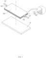
- FIG. 1 illustrates an electrode assembly 100 according to an embodiment of the present invention and arrangement of the electrode assembly 100.
- the electrode assembly 100 may include a negative electrode 110, a separator 120, and a positive electrode 130.
- the electrode assembly 100 may include the electrodes stacked alternately with the separator 120 therebetween.
- the electrodes may include a plurality of negative electrodes 110 and a plurality of positive electrodes 130.
- the electrode assembly 100 may include a negative electrode tab 140 and a negative electrode lead 141.
- the plurality of negative electrodes 110 of the electrode assembly 100 may be electrically connected to the negative electrode tab 140.
- the negative electrode tab 140 may be electrically connected to the negative electrode lead 141, and the negative electrode lead 141 may be electrically connected to the outside of the electrode assembly 100.
- the plurality of negative electrodes 110 of the electrode assembly 100 are electrically connected to the negative electrode tab 140 and the negative electrode lead 141, the plurality of negative electrodes 110 may be electrically connected to the outside of the electrode assembly 100.
- the electrode assembly 100 may include a positive electrode tab 150 and a positive electrode lead 151.
- the plurality of positive electrodes 130 of the electrode assembly 100 may be electrically connected to the positive electrode tab 150.
- the positive electrode tab 150 may be electrically connected to the positive electrode lead 151, and the positive electrode lead 151 may be electrically connected to the outside of the electrode assembly 100.
- the plurality of positive electrodes 130 of the electrode assembly 100 are electrically connected to the positive electrode tab 150 and the positive electrode lead 151, the plurality of positive electrodes 130 may be electrically connected to the outside of the electrode assembly 100.
- the electrode assembly 100 may include corner portions 301, 302, 303 and 304.
- the electrode assembly 100 may include long sides parallel to a first direction and short sides parallel to a second direction perpendicular to the first direction.
- the corner portions 301, 302, 303 and 304 may mean portions at which that the long sides meet the short sides, respectively.
- four corner portions may be formed when the electrode assembly 100 has a shape corresponding to a rectangle having four sides (or edges) when viewed from an upper side.
- four sides (or edges), each of which connects two surfaces facing each other may be the corner portions.
- the sealing of the electrode assembly 100 may be performed based on a sealing device.
- the sealing device may include a nest 10.
- the electrode assembly 100 may be disposed on the nest 10.
- the sealing device performs the sealing, the sealing of the electrode assembly 100 may be performed in a state in which the electrode assembly 100 is disposed on the nest 10.
- the sealing device may include hot air blowers 310, 320, 330 and 340, and the sealing device may control the hot air blowers 310, 320, 330 and 340.
- the hot air blowers will be described later with reference to FIGS. 2 to 5 .
- FIG. 2 illustrates a flowchart of a method for sealing an electrode assembly 100 according to another embodiment of the present invention.
- the electrode assembly 100 may be seated on a nest 10.
- the sealing may be performed in a state in which the electrode assembly 100 is seated on the nest 10 of a sealing device.
- an embodiment of the present invention is not limited thereto.
- hot air blowers 310, 320, 330 and 340 may be moved toward corner portions 301, 302, 303 and 304, respectively, of the electrode assembly 100.
- the sealing device may include the hot air blowers 310, 320, 330 and 340.
- the sealing device may control the hot air blowers 310, 320, 330 and 340 so that the hot air blowers 310, 320, 330 and 340 are moved close to the corner portions 301, 302, 303 and 304 of the electrode assembly 100, respectively.
- the sealing device may control the hot air blowers 310, 320, 330 and 340 so that the hot air blowers 310, 320, 330 and 340 are moved far away from the corner portions 301, 302, 303 and 304 of the electrode assembly 100, respectively.
- the sealing device may be provided with a plurality of hot air blowers 310, 320, 330 and 340.
- the hot air blowers 310, 320, 330 and 340 corresponding to the number of the corner portions 301, 302, 303 and 304 of the electrode assembly 100 may be provided.
- the sealing device may include a driver.
- the sealing device may use (or control) the driver to control movement of the hot air blowers 310, 320, 330 and 340.
- the sealing device may use the driver to move the hot air blowers 310, 320, 330 and 340 toward the corner portions 301, 302, 303 and 304, respectively, of the electrode assembly 100.
- the sealing device may use the driver to move the hot air blowers 310, 320, 330 and 340 to be far away from the corner portions 301, 302, 303 and 304, respectively, of the electrode assembly 100.
- the sealing device may use the driver to adjust distances between the hot air blowers 310, 320, 330 and 340 and the corner portions 301, 302, 303 and 304, respectively.
- the sealing device may be provided with a plurality of drivers.
- the sealing device may include the drivers corresponding to the number of the corner portions 301, 302, 303 and 304 of the electrode assembly 100.
- the sealing device may control the plurality of drivers simultaneously, or may control the plurality of drivers separately.
- the sealing device may control the plurality of drivers simultaneously and control the movement of the hot air blowers 310, 320, 330 and 340 simultaneously.
- the sealing device may use the plurality of drivers corresponding to the hot air blowers 310, 320, 330 and 340, respectively, and control the movement of the hot air blowers 310, 320, 330 and 340 separately.
- the hot air blowers 310, 320, 330 and 340 may be used to spray hot air and seal a separator at each of the corner portions 301, 302, 303 and 304.
- the hot air blowers 310, 320, 330 and 340 may spray the hot air.
- the hot air blowers 310, 320, 330 and 340 may at least include main bodies 311, 321, 331 and 341 and nozzles 312, 322, 332 and 342, respectively.
- the hot air blowers 310, 320, 330 and 340 may control the hot air and the nozzles 312, 322, 332 and 342, respectively.
- the hot air blowers 310, 320, 330 and 340 may adjust at least one of a temperature, pressure, or spray time of the hot air.
- the hot air blowers 310, 320, 330 and 340 may control the nozzles 312, 322, 332 and 342 to adjust spray angles, respectively.
- the angles of the nozzles 312, 322, 332 and 342 with respect to the main bodies 311, 321, 331 and 341, respectively, may be variable.
- the hot air blowers 310, 320, 330 and 340 adjust the spray angles of the nozzles 312, 322, 332 and 342, respectively, the angles of the nozzles 312, 322, 332 and 342 with respect to the main bodies 311, 321, 331 and 341, respectively, may change.
- the hot air blowers 310, 320, 330 and 340 may use the nozzles 312, 322, 332 and 342 to spray the hot air toward the corner portions 301, 302, 303 and 304 of the electrode assembly 100, respectively.
- the hot air blowers 310, 320, 330 and 340 may adjust at least one of a temperature, pressure, or spray time of the hot air to be sprayed, and the hot air blowers 310, 320, 330 and 340 may spray the hot air, of which the at least one of the temperature, pressure, or spray time has been adjusted, toward the corner portions 301, 302, 303 and 304, respectively.
- the hot air blowers 310, 320, 330 and 340 may adjust the spray angles so that the nozzles 312, 322, 332 and 342 face the corner portions 301, 302, 303 and 304, respectively, and the hot air blowers 310, 320, 330 and 340 may spray the hot air toward the corner portions 301, 302, 303 and 304 through the nozzles 312, 322, 332 and 342 at the adjusted spray angles, respectively.
- the adjusting (controlling) of the hot air and the nozzles 312, 322, 332 and 342 of the hot air blowers 310, 320, 330 and 340 may be performed in real time even during the spraying of the hot air.
- the hot air blowers 310, 320, 330 and 340 may be electrically connected to the driver.
- the controlling of the hot air and the nozzles 312, 322, 332 and 342 of the hot air blowers 310, 320, 330 and 340, which is described above, may be performed by the driver.
- the corner portions 301, 302, 303 and 304 may each include a portion of the separator 130, and the portion of the separator 130 may be sealed by the hot air.
- the portion of the separator 130 may be melted by the hot air, and the melted portion of the separator 130 may be pressed to seal each of the corner portions 301, 302, 303 and 304 of the electrode assembly 100.
- the sealing device may use the hot air blowers 310, 320, 330 and 340 to seal, in a non-contact state, the portions of the separator 130 that correspond to the corner portions 301, 302, 303 and 304 of the electrode assembly 100, respectively, and minimize a damage of the electrode and other components during the non-contact sealing.
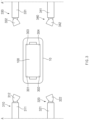
- FIG. 3 illustrates some processes of a method for sealing an electrode assembly according to an embodiment of the present invention.
- An electrode assembly 100 may be in a state of being seated on a nest 10.
- the electrode assembly 100 may include electrodes, which are stacked alternately with a separator 120 therebetween and include a plurality of negative electrodes 110 and a plurality of positive electrodes 130.
- the electrode assembly 100 may include a plurality of corner portions 301, 302, 303 and 304.
- the electrode assembly 100 may include a first corner portion 301, a second corner portion 302, a third corner portion 303 and a fourth corner portion 304.
- the plurality of corner portions 301, 302, 303 and 304 may each include a portion of the separator 120.
- the separator 120 may protrude outward from the negative electrodes 110 and the positive electrodes 130 and constitute the perimeter of the electrode assembly 100, particularly the plurality of corner portions 301, 302, 303 and 304.
- first corner portion 301 may include a portion of the separator 120, which corresponds to the first corner portion 301.
- the second corner portion 302, the third corner portion 303, and the fourth corner portion 304 may include portions of the separator 120, which correspond to the second corner portion 302, the third corner portion 303, and the fourth corner portion 304, respectively.
- Hot air blowers 310, 320, 330 and 340 may be on standby (in preparation) at positions corresponding to the plurality of corner portions 301, 302, 303 and 304, respectively.
- each of the first hot air blower 310 and the second air blower 320 may be on standby at a position corresponding to a standby line (e.g., a line A).
- each of the third hot air blower 330 and the fourth air blower 340 may be on standby at a position corresponding to a standby line (e.g., a line A').
- the hot air blowers 310, 320, 330 and 340 may be disposed apart from the plurality of corner portions 301, 302, 303 and 304, respectively, and are not limited to the examples.
- FIG. 4 illustrates a sealing process of a method for sealing an electrode assembly according to an embodiment of the present invention.
- the hot air blowers 310, 320, 330 and 340 may move to be close to the plurality of corner portions 301, 302, 303 and 304 from the positions (or standby positions), respectively, each of which corresponds to the standby line (e.g., the line A or the line A').
- a sealing device may use a driver to move the hot air blowers 310, 320, 330 and 340 to be close to the plurality of corner portions 301, 302, 303 and 304, respectively.
- the sealing device may use the driver to move each of the first hot air blower 310 and the second air blower 320 from the position corresponding to the line A to a position corresponding to a line B.
- the sealing device may use the driver to move each of the third hot air blower 330 and the fourth air blower 340 from the position corresponding to the line A' to a position corresponding to a line B'.
- the foregoing positions are described as examples, and the positions may not be limited thereto.
- the sealing device may control the driver or each of the hot air blowers 310, 320, 330 and 340 to adjust at least one of a temperature, pressure, or spray time of hot air sprayed by each of nozzles 312, 322, 332 and 342.
- the sealing device may control the driver or each of the hot air blowers 310, 320, 330 and 340 to adjust the hot air temperature, pressure, or spray time required for sealing and satisfy conditions necessary for the sealing.
- the sealing device may control the driver or each of the hot air blowers 310, 320, 330 and 340 to adjust a spray angle at which each of nozzles 312, 322, 332 and 342 sprays the hot air.
- the electrode assembly 100 may include long sides parallel to a first direction and short sides parallel to a second direction perpendicular to the first direction.
- the sealing device may control the driver or each of the hot air blowers 310, 320, 330 and 340 and adjust the spray angle of each of nozzles 312, 322, 332 and 342 so that the hot air is sprayed in a third direction in which an angle is formed with respect to the first direction and the second direction.
- the sealing device may control the driver or each of the hot air blowers 310, 320, 330 and 340 to adjust the spray angle of each of nozzles 312, 322, 332 and 342 so that the hot air is sprayed in a direction diagonal with respect to each of the plurality of corner portions 301, 302, 303 and 304.
- the sealing device may control the driver to adjust (set) distances from the hot air blowers 310, 320, 330 and 340 to the plurality of corner portions 301, 302, 303 and 304, respectively.
- the sealing device may control the driver to adjust a distance between the first hot air blower 310 and the first corner portion 301, a distance between the second hot air blower 320 and the second corner portion 302, a distance between the third hot air blower 330 and the third corner portion 303, a distance between the fourth hot air blower 340 and the fourth corner portion 304.
- the sealing device may control the driver so that the distances from the hot air blowers 310, 320, 330 and 340 to the plurality of corner portions 301, 302, 303 and 304 are the preset distance values, respectively.
- the hot air blowers 310, 320, 330 and 340 may spray the hot air at specific positions close to the plurality of corner portions 301, 302, 303 and 304, respectively.
- the sealing device may use the hot air blowers 310, 320, 330 and 340 to spray the hot air based on the set temperature, pressure, and spray time of the hot air, toward the corner portions 301, 302, 303 and 304, respectively.
- the corner portions 301, 302, 303 and 304 may each include a portion of the separator 130, and the portion of the separator 130 may be sealed in a non-contact method by the hot air.
- the portion of the separator 130 may be melted by the hot air, and the melted portion of the separator 130 may be pressed to seal each of the corner portions 301, 302, 303 and 304 of the electrode assembly 100.
- the sealing device may control the conditions for performing the sealing, such as the temperature, spray pressure, spray time, spray angle of the hot air, and the distances between the hot air blowers 310, 320, 330 and 340 and the corner portions 301, 302, 303 and 304, respectively. Accordingly, uniform and stable sealing quality may be adaptively secured.
- FIG. 5 illustrates some processes of a method for sealing an electrode assembly according to an embodiment of the present invention.
- a sealing device may control a driver to re-adjust (or re-set) distances from hot air blowers 310, 320, 330 and 340 to a plurality of corner portions 301, 302, 303 and 304, respectively.
- the sealing device may control the driver to move the hot air blowers 310, 320, 330 and 340 to initial positions, respectively.
- the sealing device may use the driver to move the hot air blowers 310, 320, 330 and 340 to be far away from the plurality of corner portions 301, 302, 303 and 304, respectively.
- the sealing device may use the driver to move each of a first hot air blower 310 and a second air blower 320 from a position corresponding to a line B to a position corresponding to a line A.
- the sealing device may use the driver to move each of a third hot air blower 330 and a fourth air blower 340 from a position corresponding to a line B' to a position corresponding to a line A'.
- the sealing device may control the driver to move the hot air blowers 310, 320, 330 and 340 from positions, which are close to the plurality of corner portions 301, 302, 303 and 304, to the positions (or standby positions), respectively, each of which corresponds to a standby line (e.g., the line A or the line A').
- a standby line e.g., the line A or the line A'
Landscapes
- Engineering & Computer Science (AREA)
- Manufacturing & Machinery (AREA)
- Chemical & Material Sciences (AREA)
- Chemical Kinetics & Catalysis (AREA)
- Electrochemistry (AREA)
- General Chemical & Material Sciences (AREA)
- Secondary Cells (AREA)
- Sealing Battery Cases Or Jackets (AREA)
Abstract
Description
- The present application claims the benefit of the priority of
Korean Patent Application No. 10-2021-0182155, filed on December 17, 2021 - The present invention relates to a method for sealing an electrode assembly, and a device for sealing an electrode assembly.
- According to a need for energy sources as alternatives to oil energy causing environmental pollution, research on and development for power generation based on energy sources such as solar heat, water power, wind power, ocean energy, and biomass energy, which have little impact on the environmental pollution, are carried out. In particular, researches on secondary batteries that can be repeatedly charged are actively carried out, and development is carried out on aspects such as the materials, efficiency, structures, and stability of the secondary batteries.
- In order to produce secondary batteries, various processes are performed, and processes are applied which correspond to various types of the secondary batteries, such as a pouch type, a prismatic type or a cylindrical type. In general, the secondary batteries are produced through processes such as an electrode process, an assembly process and a formation process, and processes to be performed may be different according to the types of the secondary batteries. In particular, with respect to the assembly process, a winding process, a stacking process, a folding process and so on are performed.
- In the assembly process of the secondary batteries, sealing for assembling and sealing the secondary batteries is performed, and the sealing is performed generally in such a way that a sealing block having a set temperature is in contact with a sealing region to thermally fuse the sealing region under a set pressure.
- According to the related art, however, the sealing block is in physical contact with the sealing region to perform the sealing. Accordingly, heat may be applied to an unintended region or an impact may be applied to an object other than an object to be sealed.
- An object to be solved by the present invention is to provide a sealing method, which is capable of sealing an object to be sealed or a sealing region without physical contact and controlling conditions for the sealing to secure sealing quality, and a sealing device for such sealing.
- A method for sealing an electrode assembly, which includes a plurality of electrodes stacked alternately with a separator therebetween, according to an embodiment of the present invention may include seating the electrode assembly on a nest, and sealing the electrode assembly by spraying hot air toward a corner portion of the electrode assembly.
- In the sealing, a hot air blower including a nozzle may be used to spray the hot air toward the corner portion.
- In the method, the hot air blower may adjust at least one of a temperature, pressure, spray time, or spray angle of the hot air.
- The method may further include moving the hot air blower toward the corner portion of the electrode assembly by using a driver before the sealing process.
- In the method, the driver may adjust a distance between the hot air blower and the corner portion.
- In the method, the electrode assembly may include long sides parallel to a first direction and short sides parallel to a second direction perpendicular to the first direction. The method may include adjusting a spray angle of the hot air with respect to the first direction and the second direction.
- In the method, the corner portion may be provided in plurality, and a plurality of hot air blowers corresponding to the number of the plurality of corner portions may be used to spray the hot air.
- A device for sealing an electrode assembly, which includes a plurality of electrodes stacked alternately with a separator therebetween, according to another embodiment of the present invention may include a nest that supports the electrode assembly, and a hot air blower that sprays hot air toward a corner portion of the electrode assembly to seal the corner portion in a non-contact state.
- The hot air blower may include a main body, and a nozzle of which an angle with respect to the main body is variable.
- The device may further include a driver that moves the hot air blower with respect to the corner portion.
- The hot air blower may adjust at least one of a temperature, pressure, spray time, or spray angle of the hot air.
- The electrode assembly may include long sides parallel to a first direction and short sides parallel to a second direction perpendicular to the first direction. The hot air blower may control the nozzle to adjust a spray angle of the hot air with respect to the first direction and the second direction.
- According to the embodiments of the present invention, the sealing may be performed in the non-contact method to minimize the impact or damage on the portion other than the object to be sealed or the sealing region, which may be caused by the physical contact during the sealing.
- According to the embodiments of the present invention, the conditions for performing the sealing may be controlled according to the situations to adaptively secure the uniform and stable sealing quality.
-
-
FIG. 1 is a view illustrating an electrode assembly according to an embodiment of the present invention and arrangement of the electrode assembly. -
FIG. 2 is a flowchart illustrating a method for sealing an electrode assembly according to another embodiment of the present invention. -
FIG. 3 is a view illustrating some processes of a method for sealing an electrode assembly according to an embodiment of the present invention. -
FIG. 4 is a view illustrating a sealing process of a method for sealing an electrode assembly according to an embodiment of the present invention. -
FIG. 5 is a view illustrating some processes of a method for sealing an electrode assembly according to an embodiment of the present invention. - Hereinafter, preferred embodiments of the present invention will be described in detail with reference to the accompanying drawings to enable those skilled in the art to which the present invention pertains to easily carry out the present invention. The present invention may, however, be embodied in different forms and should not be construed as limited by the embodiments set forth herein.
- The parts unrelated to the description, or the detailed descriptions of related well-known art that may unnecessarily obscure subject matters of the present invention, will be ruled out in order to clearly describe the present invention. Like reference numerals refer to like elements throughout the whole specification.
- Moreover, terms or words used in this specification and claims should not be restrictively interpreted as ordinary meanings or dictionary-based meanings, but should be interpreted as meanings and concepts conforming to the scope of the present invention on the basis of the principle that an inventor can properly define the concept of a term to describe and explain his or her invention in the best ways.
-
FIG. 1 illustrates anelectrode assembly 100 according to an embodiment of the present invention and arrangement of theelectrode assembly 100. - The
electrode assembly 100 may include anegative electrode 110, aseparator 120, and apositive electrode 130. For example, theelectrode assembly 100 may include the electrodes stacked alternately with theseparator 120 therebetween. The electrodes may include a plurality ofnegative electrodes 110 and a plurality ofpositive electrodes 130. - The
electrode assembly 100 may include anegative electrode tab 140 and anegative electrode lead 141. For example, the plurality ofnegative electrodes 110 of theelectrode assembly 100 may be electrically connected to thenegative electrode tab 140. Thenegative electrode tab 140 may be electrically connected to thenegative electrode lead 141, and thenegative electrode lead 141 may be electrically connected to the outside of theelectrode assembly 100. As the plurality ofnegative electrodes 110 of theelectrode assembly 100 are electrically connected to thenegative electrode tab 140 and thenegative electrode lead 141, the plurality ofnegative electrodes 110 may be electrically connected to the outside of theelectrode assembly 100. - The
electrode assembly 100 may include apositive electrode tab 150 and apositive electrode lead 151. For example, the plurality ofpositive electrodes 130 of theelectrode assembly 100 may be electrically connected to thepositive electrode tab 150. Thepositive electrode tab 150 may be electrically connected to thepositive electrode lead 151, and thepositive electrode lead 151 may be electrically connected to the outside of theelectrode assembly 100. As the plurality ofpositive electrodes 130 of theelectrode assembly 100 are electrically connected to thepositive electrode tab 150 and thepositive electrode lead 151, the plurality ofpositive electrodes 130 may be electrically connected to the outside of theelectrode assembly 100. - The
electrode assembly 100 may includecorner portions electrode assembly 100 may include long sides parallel to a first direction and short sides parallel to a second direction perpendicular to the first direction. Thecorner portions electrode assembly 100 has a shape corresponding to a rectangle having four sides (or edges) when viewed from an upper side. For still another example, when theelectrode assembly 100 has a shape corresponding to a hexahedron, four sides (or edges), each of which connects two surfaces facing each other, may be the corner portions. - The sealing of the
electrode assembly 100 may be performed based on a sealing device. - The sealing device may include a
nest 10. For example, theelectrode assembly 100 may be disposed on thenest 10. When the sealing device performs the sealing, the sealing of theelectrode assembly 100 may be performed in a state in which theelectrode assembly 100 is disposed on thenest 10. - The sealing device may include
hot air blowers hot air blowers FIGS. 2 to 5 . -
FIG. 2 illustrates a flowchart of a method for sealing anelectrode assembly 100 according to another embodiment of the present invention. - According to a
process 210, theelectrode assembly 100 may be seated on anest 10. - The sealing may be performed in a state in which the
electrode assembly 100 is seated on thenest 10 of a sealing device. However, an embodiment of the present invention is not limited thereto. - According to a
process 220,hot air blowers corner portions electrode assembly 100. - The sealing device may include the
hot air blowers - The sealing device may control the
hot air blowers hot air blowers corner portions electrode assembly 100, respectively. The sealing device may control thehot air blowers hot air blowers corner portions electrode assembly 100, respectively. - The sealing device may be provided with a plurality of
hot air blowers hot air blowers corner portions electrode assembly 100 may be provided. - The sealing device may include a driver.
- The sealing device may use (or control) the driver to control movement of the
hot air blowers hot air blowers corner portions electrode assembly 100. For another example, the sealing device may use the driver to move thehot air blowers corner portions electrode assembly 100. For still another example, the sealing device may use the driver to adjust distances between thehot air blowers corner portions - The sealing device may be provided with a plurality of drivers. For example, the sealing device may include the drivers corresponding to the number of the
corner portions electrode assembly 100. - The sealing device may control the plurality of drivers simultaneously, or may control the plurality of drivers separately. For example, the sealing device may control the plurality of drivers simultaneously and control the movement of the
hot air blowers hot air blowers hot air blowers - According to a
process 230, thehot air blowers corner portions - The
hot air blowers - The
hot air blowers main bodies nozzles - The
hot air blowers nozzles hot air blowers hot air blowers nozzles - The angles of the
nozzles main bodies hot air blowers nozzles nozzles main bodies - The
hot air blowers nozzles corner portions electrode assembly 100, respectively. For example, thehot air blowers hot air blowers corner portions hot air blowers nozzles corner portions hot air blowers corner portions nozzles - The adjusting (controlling) of the hot air and the
nozzles hot air blowers - The
hot air blowers main bodies nozzles hot air blowers - The
corner portions separator 130, and the portion of theseparator 130 may be sealed by the hot air. For example, the portion of theseparator 130 may be melted by the hot air, and the melted portion of theseparator 130 may be pressed to seal each of thecorner portions electrode assembly 100. - According to the foregoing, the sealing device may use the
hot air blowers separator 130 that correspond to thecorner portions electrode assembly 100, respectively, and minimize a damage of the electrode and other components during the non-contact sealing. -
FIG. 3 illustrates some processes of a method for sealing an electrode assembly according to an embodiment of the present invention. - An
electrode assembly 100 may be in a state of being seated on anest 10. - The
electrode assembly 100 may include electrodes, which are stacked alternately with aseparator 120 therebetween and include a plurality ofnegative electrodes 110 and a plurality ofpositive electrodes 130. - The
electrode assembly 100 may include a plurality ofcorner portions electrode assembly 100 may include afirst corner portion 301, asecond corner portion 302, athird corner portion 303 and afourth corner portion 304. - The plurality of
corner portions separator 120. In more detail, theseparator 120 may protrude outward from thenegative electrodes 110 and thepositive electrodes 130 and constitute the perimeter of theelectrode assembly 100, particularly the plurality ofcorner portions - For example, the
first corner portion 301 may include a portion of theseparator 120, which corresponds to thefirst corner portion 301. For another example, thesecond corner portion 302, thethird corner portion 303, and thefourth corner portion 304 may include portions of theseparator 120, which correspond to thesecond corner portion 302, thethird corner portion 303, and thefourth corner portion 304, respectively. -
Hot air blowers corner portions hot air blower 310 and thesecond air blower 320 may be on standby at a position corresponding to a standby line (e.g., a line A). For another example, each of the thirdhot air blower 330 and thefourth air blower 340 may be on standby at a position corresponding to a standby line (e.g., a line A'). The foregoing standby lines are examples. Thehot air blowers corner portions -
FIG. 4 illustrates a sealing process of a method for sealing an electrode assembly according to an embodiment of the present invention. - The
hot air blowers corner portions - A sealing device may use a driver to move the
hot air blowers corner portions hot air blower 310 and thesecond air blower 320 from the position corresponding to the line A to a position corresponding to a line B. For another example, the sealing device may use the driver to move each of the thirdhot air blower 330 and thefourth air blower 340 from the position corresponding to the line A' to a position corresponding to a line B'. The foregoing positions are described as examples, and the positions may not be limited thereto. - The sealing device may control the driver or each of the
hot air blowers nozzles hot air blowers - The sealing device may control the driver or each of the
hot air blowers nozzles electrode assembly 100 may include long sides parallel to a first direction and short sides parallel to a second direction perpendicular to the first direction. The sealing device may control the driver or each of thehot air blowers nozzles hot air blowers nozzles corner portions - The sealing device may control the driver to adjust (set) distances from the
hot air blowers corner portions hot air blower 310 and thefirst corner portion 301, a distance between the secondhot air blower 320 and thesecond corner portion 302, a distance between the thirdhot air blower 330 and thethird corner portion 303, a distance between the fourthhot air blower 340 and thefourth corner portion 304. - When there are preset distance values, the sealing device may control the driver so that the distances from the
hot air blowers corner portions - The
hot air blowers corner portions corner portions nozzles hot air blowers corner portions - The
corner portions separator 130, and the portion of theseparator 130 may be sealed in a non-contact method by the hot air. For example, the portion of theseparator 130 may be melted by the hot air, and the melted portion of theseparator 130 may be pressed to seal each of thecorner portions electrode assembly 100. - As the sealing device performs the sealing in the non-contact method by using the
hot air blowers hot air blowers corner portions -
FIG. 5 illustrates some processes of a method for sealing an electrode assembly according to an embodiment of the present invention. - A sealing device may control a driver to re-adjust (or re-set) distances from
hot air blowers corner portions hot air blowers - The sealing device may use the driver to move the
hot air blowers corner portions hot air blower 310 and asecond air blower 320 from a position corresponding to a line B to a position corresponding to a line A. For another example, the sealing device may use the driver to move each of a thirdhot air blower 330 and afourth air blower 340 from a position corresponding to a line B' to a position corresponding to a line A'. - The sealing device may control the driver to move the
hot air blowers corner portions - Although the present invention has been described with reference to the limited embodiments and drawings, the present invention is not limited thereto and may be variously implemented by those of ordinary skill in the art to which the present invention pertains, within the technical idea of the present invention and an equivalent of the appended claims.
-
- 10: Nest
- 100: Electrode assembly
- 110: Negative electrode
- 120: Separator
- 130: Positive electrode
- 140: Negative electrode tab
- 141: Negative electrode lead
- 150: Positive electrode tab
- 151: Positive electrode lead
- 301: First corner portion
- 302: Second corner portion
- 303: Third corner portion
- 304: Fourth corner portion
- 310: First hot air blower
- 311: First main body
- 312: First nozzle
- 320: Second hot air blower
- 321: Second main body
- 322: Second nozzle
- 330: Third hot air blower
- 331: Third main body
- 332: Third nozzle
- 340: Fourth hot air blower
- 341: Fourth main body
- 342: Fourth nozzle
Claims (12)
- A method for sealing an electrode assembly comprising a plurality of electrodes stacked alternately with a separator therebetween, the method comprising:seating the electrode assembly on a nest; andsealing the electrode assembly by spraying hot air toward a corner portion of the electrode assembly,
- The method of claim 1, wherein, in the sealing, a hot air blower comprising a nozzle is used to spray the hot air toward the corner portion.
- The method of claim 2, wherein the hot air blower adjusts at least one of a temperature, pressure, spray time, or spray angle of the hot air.
- The method of claim 2, further comprising moving the hot air blower toward the corner portion of the electrode assembly by using a driver before the sealing.
- The method of claim 4, wherein the driver adjusts a distance between the hot air blower and the corner portion.
- The method of claim 2, wherein the electrode assembly comprises long sides parallel to a first direction and short sides parallel to a second direction perpendicular to the first direction,
wherein the method comprises adjusting a spray angle of the hot air with respect to the first direction and the second direction. - The method of claim 2, wherein the corner portion is provided in plurality,
wherein a plurality of hot air blowers corresponding to the number of the plurality of corner portions are used to splay the hot air. - A device for sealing an electrode assembly comprising a plurality of electrodes stacked alternately with a separator therebetween, the device comprising:a nest configured to support the electrode assembly; anda hot air blower configured to spray hot air toward a corner portion of the electrode assembly to seal the corner portion in a non-contact state.
- The device of claim 8, wherein the hot air blower comprises:a main body; anda nozzle of which an angle with respect to the main body is variable.
- The device of claim 9, further comprising a driver configured to move the hot air blower with respect to the corner portion.
- The device of claim 9, wherein the hot air blower adjusts at least one of a temperature, pressure, spray time, or spray angle of the hot air.
- The device of claim 9, wherein the electrode assembly comprises long sides parallel to a first direction and short sides parallel to a second direction perpendicular to the first direction,
wherein the hot air blower controls the nozzle to adjust a spray angle of the hot air with respect to the first direction and the second direction.
Applications Claiming Priority (2)
| Application Number | Priority Date | Filing Date | Title |
|---|---|---|---|
| KR1020210182155A KR102875758B1 (en) | 2021-12-17 | 2021-12-17 | Method for sealing electrode assembly and sealing device for the same |
| PCT/KR2022/019521 WO2023113329A1 (en) | 2021-12-17 | 2022-12-02 | Method for sealing electrode assembly and sealing device therefor |
Publications (3)
| Publication Number | Publication Date |
|---|---|
| EP4322272A1 true EP4322272A1 (en) | 2024-02-14 |
| EP4322272A4 EP4322272A4 (en) | 2025-04-23 |
| EP4322272B1 EP4322272B1 (en) | 2026-04-15 |
Family
ID=86773070
Family Applications (1)
| Application Number | Title | Priority Date | Filing Date |
|---|---|---|---|
| EP22907798.7A Active EP4322272B1 (en) | 2021-12-17 | 2022-12-02 | Method for sealing electrode assembly and sealing device therefor |
Country Status (6)
| Country | Link |
|---|---|
| US (1) | US20240379987A1 (en) |
| EP (1) | EP4322272B1 (en) |
| JP (1) | JP7683152B2 (en) |
| KR (1) | KR102875758B1 (en) |
| CN (1) | CN117546327A (en) |
| WO (1) | WO2023113329A1 (en) |
Families Citing this family (1)
| Publication number | Priority date | Publication date | Assignee | Title |
|---|---|---|---|---|
| KR20250080769A (en) | 2023-11-28 | 2025-06-05 | 주식회사 엘지에너지솔루션 | Electrode assembly separator corner sealing device and sealing method |
Family Cites Families (14)
| Publication number | Priority date | Publication date | Assignee | Title |
|---|---|---|---|---|
| JPH01122574A (en) * | 1987-11-06 | 1989-05-15 | Matsushita Electric Ind Co Ltd | Cylindrical lithium secondary battery |
| JP3227773B2 (en) * | 1992-03-13 | 2001-11-12 | 日本電池株式会社 | Sealed lead-acid battery |
| JPH1064506A (en) * | 1996-08-19 | 1998-03-06 | Shin Kobe Electric Mach Co Ltd | Prismatic battery |
| JP2002298924A (en) * | 2001-03-30 | 2002-10-11 | Toray Eng Co Ltd | Secondary battery, secondary battery manufacturing method, and secondary battery manufacturing apparatus |
| JP6351930B2 (en) * | 2012-08-21 | 2018-07-04 | 積水化学工業株式会社 | Method for producing multilayer membrane electrode assembly |
| JP6058783B2 (en) * | 2013-03-05 | 2017-01-11 | 協立化学産業株式会社 | Battery electrode or separator coating film composition, battery electrode or separator having a coating film obtained by using the same, and battery having this battery electrode or separator |
| JP6569230B2 (en) * | 2015-02-06 | 2019-09-04 | 日産自動車株式会社 | Secondary battery and manufacturing method thereof |
| JP6620068B2 (en) | 2016-06-03 | 2019-12-11 | 株式会社オザワエナックス | Manufacturing method of sheet-like lithium ion secondary battery |
| JP6640690B2 (en) | 2016-09-21 | 2020-02-05 | 株式会社東芝 | Electrode structure, secondary battery, battery pack and vehicle |
| JP2018116823A (en) * | 2017-01-18 | 2018-07-26 | パナソニックIpマネジメント株式会社 | Manufacturing apparatus and manufacturing method of electrolyte membrane-electrode assembly |
| JP6874482B2 (en) | 2017-03-31 | 2021-05-19 | 株式会社豊田自動織機 | Power storage module and its manufacturing method |
| JP6772972B2 (en) * | 2017-07-03 | 2020-10-21 | トヨタ自動車株式会社 | Manufacturing method of laminated solid-state battery |
| JP2019029065A (en) | 2017-07-25 | 2019-02-21 | 株式会社豊田自動織機 | Device and method for manufacturing electrode body |
| JP6959526B2 (en) * | 2017-12-28 | 2021-11-02 | 株式会社豊田自動織機 | Electrode unit manufacturing equipment |
-
2021
- 2021-12-17 KR KR1020210182155A patent/KR102875758B1/en active Active
-
2022
- 2022-12-02 JP JP2023568186A patent/JP7683152B2/en active Active
- 2022-12-02 EP EP22907798.7A patent/EP4322272B1/en active Active
- 2022-12-02 US US18/564,351 patent/US20240379987A1/en active Pending
- 2022-12-02 WO PCT/KR2022/019521 patent/WO2023113329A1/en not_active Ceased
- 2022-12-02 CN CN202280044486.1A patent/CN117546327A/en active Pending
Also Published As
| Publication number | Publication date |
|---|---|
| JP2024517006A (en) | 2024-04-18 |
| US20240379987A1 (en) | 2024-11-14 |
| KR20230092613A (en) | 2023-06-26 |
| KR102875758B1 (en) | 2025-10-24 |
| EP4322272A4 (en) | 2025-04-23 |
| WO2023113329A1 (en) | 2023-06-22 |
| EP4322272B1 (en) | 2026-04-15 |
| CN117546327A (en) | 2024-02-09 |
| JP7683152B2 (en) | 2025-05-27 |
Similar Documents
| Publication | Publication Date | Title |
|---|---|---|
| EP4322272B1 (en) | Method for sealing electrode assembly and sealing device therefor | |
| JP2021507477A (en) | Electrochemical system | |
| US20120276435A1 (en) | Method of forming encapsulated solid electrochemical component | |
| US20240313296A1 (en) | Battery, electrical apparatus, method for preparing battery, and apparatus for preparing battery | |
| KR20240030290A (en) | Marking generation device | |
| KR102265849B1 (en) | Electrode for secondary battery, method for manufacturing the same and electrode assembly | |
| JP7618816B2 (en) | Battery cell and its manufacturing method, manufacturing device, battery, and power consumption device | |
| US20250233289A1 (en) | Battery cell, battery, and electric device | |
| EP3496195B1 (en) | Separator plate and fuel cell stack comprising same | |
| EP4527540A1 (en) | Etching machine | |
| KR102322077B1 (en) | Secondary battery stacking device with folding plate | |
| KR20250123184A (en) | Battery cells, batteries and electrical devices | |
| KR102848111B1 (en) | Electrode assembly and secondary battery comprising the same | |
| EP4715999A1 (en) | Anode for lithium metal battery, electrode assembly for lithium metal battery, and lithium metal battery | |
| KR20260056640A (en) | Battery cell Manufacturing Apparatus and Method | |
| KR20250149524A (en) | Method and device for welding case-cap | |
| US20250183432A1 (en) | Battery cell and battery cell manufacturing method | |
| US20260074329A1 (en) | Battery and method for manufacturing the same | |
| US20250246723A1 (en) | Housing, battery cell, battery, and electric device | |
| KR102940382B1 (en) | Automatic adjustment device for taping device for secondary battery | |
| EP4550491A1 (en) | Folding device and folding method | |
| US20240178436A1 (en) | Battery cell pressing device | |
| CN115939430B (en) | Battery pack adjusting device | |
| US20260142345A1 (en) | Secondary battery and method of manufacturing the secondary battery | |
| US20240313295A1 (en) | Battery, electrical apparatus, method for preparing battery, and apparatus for preparing battery |
Legal Events
| Date | Code | Title | Description |
|---|---|---|---|
| STAA | Information on the status of an ep patent application or granted ep patent |
Free format text: STATUS: THE INTERNATIONAL PUBLICATION HAS BEEN MADE |
|
| PUAI | Public reference made under article 153(3) epc to a published international application that has entered the european phase |
Free format text: ORIGINAL CODE: 0009012 |
|
| STAA | Information on the status of an ep patent application or granted ep patent |
Free format text: STATUS: REQUEST FOR EXAMINATION WAS MADE |
|
| 17P | Request for examination filed |
Effective date: 20231106 |
|
| AK | Designated contracting states |
Kind code of ref document: A1 Designated state(s): AL AT BE BG CH CY CZ DE DK EE ES FI FR GB GR HR HU IE IS IT LI LT LU LV MC ME MK MT NL NO PL PT RO RS SE SI SK SM TR |
|
| DAV | Request for validation of the european patent (deleted) | ||
| DAX | Request for extension of the european patent (deleted) | ||
| A4 | Supplementary search report drawn up and despatched |
Effective date: 20250321 |
|
| RIC1 | Information provided on ipc code assigned before grant |
Ipc: H01M 10/0585 20100101ALI20250317BHEP Ipc: H01M 10/04 20060101AFI20250317BHEP |
|
| RIC1 | Information provided on ipc code assigned before grant |
Ipc: H01M 10/04 20060101AFI20251202BHEP Ipc: H01M 10/0585 20100101ALI20251202BHEP |
|
| GRAP | Despatch of communication of intention to grant a patent |
Free format text: ORIGINAL CODE: EPIDOSNIGR1 |
|
| STAA | Information on the status of an ep patent application or granted ep patent |
Free format text: STATUS: GRANT OF PATENT IS INTENDED |
|
| INTG | Intention to grant announced |
Effective date: 20260112 |
|
| GRAS | Grant fee paid |
Free format text: ORIGINAL CODE: EPIDOSNIGR3 |
|
| GRAA | (expected) grant |
Free format text: ORIGINAL CODE: 0009210 |
|
| STAA | Information on the status of an ep patent application or granted ep patent |
Free format text: STATUS: THE PATENT HAS BEEN GRANTED |
|
| AK | Designated contracting states |
Kind code of ref document: B1 Designated state(s): AL AT BE BG CH CY CZ DE DK EE ES FI FR GB GR HR HU IE IS IT LI LT LU LV MC ME MK MT NL NO PL PT RO RS SE SI SK SM TR |
|
| REG | Reference to a national code |
Ref country code: CH Ref legal event code: F10 Free format text: ST27 STATUS EVENT CODE: U-0-0-F10-F00 (AS PROVIDED BY THE NATIONAL OFFICE) Effective date: 20260415 |
|
| REG | Reference to a national code |
Ref country code: DE Ref legal event code: R096 Ref document number: 602022034807 Country of ref document: DE |