EP4322240A1 - Drying apparatus capable of automatically adjusting screen - Google Patents
Drying apparatus capable of automatically adjusting screen Download PDFInfo
- Publication number
- EP4322240A1 EP4322240A1 EP23747329.3A EP23747329A EP4322240A1 EP 4322240 A1 EP4322240 A1 EP 4322240A1 EP 23747329 A EP23747329 A EP 23747329A EP 4322240 A1 EP4322240 A1 EP 4322240A1
- Authority
- EP
- European Patent Office
- Prior art keywords
- opening
- shield film
- drying device
- region
- sensing
- Prior art date
- Legal status (The legal status is an assumption and is not a legal conclusion. Google has not performed a legal analysis and makes no representation as to the accuracy of the status listed.)
- Granted
Links
Images



Classifications
-
- F—MECHANICAL ENGINEERING; LIGHTING; HEATING; WEAPONS; BLASTING
- F26—DRYING
- F26B—DRYING SOLID MATERIALS OR OBJECTS BY REMOVING LIQUID THEREFROM
- F26B13/00—Machines and apparatus for drying fabrics, fibres, yarns, or other materials in long lengths, with progressive movement
- F26B13/001—Drying and oxidising yarns, ribbons or the like
- F26B13/002—Drying coated, e.g. enamelled, varnished, wires
-
- F—MECHANICAL ENGINEERING; LIGHTING; HEATING; WEAPONS; BLASTING
- F26—DRYING
- F26B—DRYING SOLID MATERIALS OR OBJECTS BY REMOVING LIQUID THEREFROM
- F26B21/00—Arrangements for supplying or controlling air or other gases for drying solid materials or objects
- F26B21/30—Controlling, e.g. regulating, parameters of gas supply
-
- F—MECHANICAL ENGINEERING; LIGHTING; HEATING; WEAPONS; BLASTING
- F26—DRYING
- F26B—DRYING SOLID MATERIALS OR OBJECTS BY REMOVING LIQUID THEREFROM
- F26B13/00—Machines and apparatus for drying fabrics, fibres, yarns, or other materials in long lengths, with progressive movement
- F26B13/007—Treating a particular portion of the web or plate, e.g. the edge
-
- F—MECHANICAL ENGINEERING; LIGHTING; HEATING; WEAPONS; BLASTING
- F26—DRYING
- F26B—DRYING SOLID MATERIALS OR OBJECTS BY REMOVING LIQUID THEREFROM
- F26B13/00—Machines and apparatus for drying fabrics, fibres, yarns, or other materials in long lengths, with progressive movement
- F26B13/10—Arrangements for feeding, heating or supporting materials; Controlling movement, tension or position of materials
-
- F—MECHANICAL ENGINEERING; LIGHTING; HEATING; WEAPONS; BLASTING
- F26—DRYING
- F26B—DRYING SOLID MATERIALS OR OBJECTS BY REMOVING LIQUID THEREFROM
- F26B13/00—Machines and apparatus for drying fabrics, fibres, yarns, or other materials in long lengths, with progressive movement
- F26B13/10—Arrangements for feeding, heating or supporting materials; Controlling movement, tension or position of materials
- F26B13/108—Arrangements for feeding, heating or supporting materials; Controlling movement, tension or position of materials using one or more blowing devices, e.g. nozzle bar, the effective area of which is adjustable to the width of the material
-
- F—MECHANICAL ENGINEERING; LIGHTING; HEATING; WEAPONS; BLASTING
- F26—DRYING
- F26B—DRYING SOLID MATERIALS OR OBJECTS BY REMOVING LIQUID THEREFROM
- F26B21/00—Arrangements for supplying or controlling air or other gases for drying solid materials or objects
- F26B21/50—Ducting arrangements from the source of air or other gases to the materials or objects being dried
-
- F—MECHANICAL ENGINEERING; LIGHTING; HEATING; WEAPONS; BLASTING
- F26—DRYING
- F26B—DRYING SOLID MATERIALS OR OBJECTS BY REMOVING LIQUID THEREFROM
- F26B25/00—Details of general application not covered by group F26B21/00 or F26B23/00
- F26B25/06—Chambers, containers, or receptacles
- F26B25/066—Movable chambers, e.g. collapsible, demountable
-
- F—MECHANICAL ENGINEERING; LIGHTING; HEATING; WEAPONS; BLASTING
- F26—DRYING
- F26B—DRYING SOLID MATERIALS OR OBJECTS BY REMOVING LIQUID THEREFROM
- F26B3/00—Drying solid materials or objects by processes involving the application of heat
- F26B3/02—Drying solid materials or objects by processes involving the application of heat by convection, i.e. heat being conveyed from a heat source to the materials or objects to be dried by a gas or vapour, e.g. air
- F26B3/04—Drying solid materials or objects by processes involving the application of heat by convection, i.e. heat being conveyed from a heat source to the materials or objects to be dried by a gas or vapour, e.g. air the gas or vapour circulating over or surrounding the materials or objects to be dried
-
- F—MECHANICAL ENGINEERING; LIGHTING; HEATING; WEAPONS; BLASTING
- F26—DRYING
- F26B—DRYING SOLID MATERIALS OR OBJECTS BY REMOVING LIQUID THEREFROM
- F26B3/00—Drying solid materials or objects by processes involving the application of heat
- F26B3/28—Drying solid materials or objects by processes involving the application of heat by radiation, e.g. from the sun
- F26B3/30—Drying solid materials or objects by processes involving the application of heat by radiation, e.g. from the sun from infrared-emitting elements
-
- H—ELECTRICITY
- H01—ELECTRIC ELEMENTS
- H01M—PROCESSES OR MEANS, e.g. BATTERIES, FOR THE DIRECT CONVERSION OF CHEMICAL ENERGY INTO ELECTRICAL ENERGY
- H01M4/00—Electrodes
- H01M4/02—Electrodes composed of, or comprising, active material
- H01M4/04—Processes of manufacture in general
-
- H—ELECTRICITY
- H01—ELECTRIC ELEMENTS
- H01M—PROCESSES OR MEANS, e.g. BATTERIES, FOR THE DIRECT CONVERSION OF CHEMICAL ENERGY INTO ELECTRICAL ENERGY
- H01M4/00—Electrodes
- H01M4/02—Electrodes composed of, or comprising, active material
- H01M4/04—Processes of manufacture in general
- H01M4/0402—Methods of deposition of the material
- H01M4/0404—Methods of deposition of the material by coating on electrode collectors
-
- H—ELECTRICITY
- H01—ELECTRIC ELEMENTS
- H01M—PROCESSES OR MEANS, e.g. BATTERIES, FOR THE DIRECT CONVERSION OF CHEMICAL ENERGY INTO ELECTRICAL ENERGY
- H01M4/00—Electrodes
- H01M4/02—Electrodes composed of, or comprising, active material
- H01M4/04—Processes of manufacture in general
- H01M4/0471—Processes of manufacture in general involving thermal treatment, e.g. firing, sintering, backing particulate active material, thermal decomposition, pyrolysis
-
- Y—GENERAL TAGGING OF NEW TECHNOLOGICAL DEVELOPMENTS; GENERAL TAGGING OF CROSS-SECTIONAL TECHNOLOGIES SPANNING OVER SEVERAL SECTIONS OF THE IPC; TECHNICAL SUBJECTS COVERED BY FORMER USPC CROSS-REFERENCE ART COLLECTIONS [XRACs] AND DIGESTS
- Y02—TECHNOLOGIES OR APPLICATIONS FOR MITIGATION OR ADAPTATION AGAINST CLIMATE CHANGE
- Y02E—REDUCTION OF GREENHOUSE GAS [GHG] EMISSIONS, RELATED TO ENERGY GENERATION, TRANSMISSION OR DISTRIBUTION
- Y02E60/00—Enabling technologies; Technologies with a potential or indirect contribution to GHG emissions mitigation
- Y02E60/10—Energy storage using batteries
Definitions
- the present invention relates to a drying device, which relates to, particularly, a drying device with an automatically adjustable shield film, and relates to, specifically, a drying device with an automatically adjustable shield film, in which a shielding region can be automatically set according to the extent that a shield film part opens and closes an opening.
- a secondary battery is generally composed of electrodes (positive and negative electrodes), a separator, and an electrolyte, and is manufactured through a series of steps including an electrode process, an assembly process, and an activation process.
- the positive electrode and the negative electrode are manufactured by coating an active material-containing slurry on a current collector of a sheet, mesh, film, or foil, and the like of aluminum or copper, followed by drying.
- the electrode process is also referred to as a polar plate process, which is a process of manufacturing a positive electrode and a negative electrode, which are essential components of a secondary battery.
- the electrode process specifically comprises a mixing process, a coating process, a rolling (calendar) process, a slitting process, and a drying process.
- the positive electrode slurry prepared in the mixing process is applied to the positive electrode current collector in the coating process.
- the negative electrode slurry is also applied to the negative electrode current collector in the coating process.
- the current collector applied with the slurry is cut to meet the designed standard through the rolling process and the slitting process.
- moisture in the slurry applied to each current collector is removed through the drying process before entering the assembly process.
- hot air or infrared rays are mainly used to dry the coated slurry.
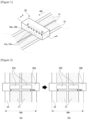
- Figures 1 and 2 are views for explaining a process of drying a current collector using a drying device equipped with a shield according to the conventional technology, where Figure 2 schematically depicts a cross-section of a state cut along the line A-A in Figure 1 .
- the drying degree difference of the slurry (11) in the width direction of the current collector (10) occurs at the edges of the current collector (10) and the center portion of the current collector (10).
- defects such as cracks occur on the surface to be dried.
- the use of a shield (20a) with different specifications is required.
- the shields (20a, 20b) to match each model according to the widths (Wa, Wb) of the current collector (10) are replaced and used.
- a shield A (20a) having the specification according to Model A is used.
- the opening (21a) of the shield A (20a) has a width (W1) of 800mm.
- a shield B (20b) having the specification according to Model B is used.
- the opening (21b) of the shield B (20b) has a width (W2) of 900mm.
- the time loss occurs as the process is stopped during the replacement time, and the process instability occurs due to improper installation of the shields.
- the thermal expansion coefficients of the coated portion (11, portion where the slurry is applied) and the uncoated portion (portion where the slurry is not applied) of the current collector (10) are different from each other, so that there may be a problem of the electrode, such as wrinkles or cracks.
- the problem of the electrode may affect the adhesion force between the slurry (11) and the current collector (10), and in this case, there may be a problem such as separation of the slurry and the current collector (10) during subsequent processes.
- the present invention is intended to provide a drying device with an automatically adjustable shield film in which a shielding region can be automatically set according to the extent that a shield film part opens and closes an opening.
- a drying device with an automatically adjustable shield film comprises: a housing installed on a transport path of a base material and having an opening on a reference surface facing the base material; a dry part installed in the housing to provide heat to the base material through the opening; a shield film part provided to cover a partial region of the opening and movably provided along the longitudinal direction of the opening to adjust an open area of the opening; a sensing part provided to sense a region where the shield film part covers the opening; and a control part controlling operation of the shield film part based on coating pattern information including width information of the base material and width information of a slurry applied to the base material, and sensing information of the sensing part.
- the shield film part may be provided to move in a unit of 1/n (n is a natural number of 2 or more) of the opening area toward a close direction based on both edges of the opening, where the close direction may be a direction moving from the edges of the opening toward the center of the opening.
- the shield film part may be provided to move in a unit of 1/n (n is a natural number of 2 or more) of the opening area toward an open direction, where the open direction may be a direction moving from the center of the opening toward the edges of the opening.
- the shield film part may comprise a pair of guide members installed on the reference surface along the longitudinal direction of the opening, and a plurality of shield film units movably installed on the pair of guide members and operated to cover one region or the entire region of the opening while moving in a close direction or an open direction.
- the close direction may be a direction moving from the edges of the opening toward the center of the opening
- the open direction may be a direction opposite to the close direction.
- the plurality of shield film units may comprise a first shield film unit covering one region of the opening while moving along the pair of guide members and a second shield film unit covering the other region of the opening while moving along the pair of guide members.
- the first shield film unit may comprise, on one side of the opening, a first reference bar installed on the reference surface, a first shield film member moving in the close direction or the open direction, wherein one end is wound around the first reference bar, and the other end is provided to be movable to the pair of guide members, along a rotation direction of the first reference bar, and a first drive unit providing rotative force to the first reference bar.
- the second shield film unit may comprise, on the other side of the opening, a second reference bar installed on the reference surface, a second shield film member moving in the close direction or the open direction, wherein one end is wound around the second reference bar, and the other end is provided to be movable to the pair of guide members, along a rotation direction of the second reference bar, and a second drive unit providing rotative force to the second reference bar.
- the first shield film unit comprises a plurality of first shield film members covering 1/n (n is a natural number of 2 or more) of the opening area, where the plurality of first shield film members may be provided to be folded and unfolded in multiple stages along the pair of guide members.
- the second shield film unit comprises a plurality of second shield film members covering 1/n (n is a natural number of 2 or more) of the opening area, where the plurality of second shield film members may be provided to be folded and unfolded in multiple stages along the pair of guide members.
- the sensing part comprises a plurality of sensing sensors, where the plurality of sensing sensors may be disposed apart in a line along the longitudinal direction of the opening.
- the plurality of sensing sensors may be disposed apart from each other at intervals of 1/n (n is a natural number of 2 or more) of the opening length.
- the plurality of sensing sensors may be disposed on an opposite surface of the housing facing the opening.
- control part may calculate a close region in which the shield film part covers the opening based on the sensing information of the sensing sensor, and adjust an open region of the opening through the shield film part based on the coating pattern information.
- a shielding region can be automatically set according to the extent that a shield film part opens and closes an opening, a time loss of shield film replacement can be reduced, and drying defects due to improper installation of the shield film can be improved.
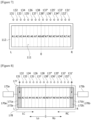
- Figure 3 schematically illustrates an installation state diagram of a drying device with an automatically adjustable shield film according to one example of the present invention
- Figure 4 schematically illustrates a cross-section of a drying device with an automatically adjustable shield film taken along the B-B cross-section of Figure 3
- Figure 5 is a view for explaining a process of providing heat to a base material upon operation of a drying device.
- Figure 6 schematically illustrates a configuration diagram of a drying device with an automatically adjustable shield film according to one example of the present invention.
- a drying device (100) with an automatically adjustable shield film comprises a housing (110), a control part (120), a sensing part (130), a dry part (150), and a shield film part (170).
- the drying device (100) comprises a housing (110) installed on a transport path of a base material (10) and having an opening (111) on a reference surface (112) facing the base material (10), a dry part (150) installed in the housing (110) to provide heat to the base material (10) through the opening (111), a shield film part (170) provided to cover a partial region of the opening (111) and movably provided along the longitudinal direction of the opening (111) to adjust an open area of the opening (111), a sensing part (130) provided to sense a region where the shield film part (170) covers the opening (111), and a control part (120) controlling operation of the shield film part (170) based on coating pattern information including width information of the base material (10) and width information of a slurry (11) applied to the base material (10), and sensing information of the sensing part (130).
- the housing (110) is installed on the transport path (MD) of the base material (10).
- the housing (110) is provided with the opening (111) on the reference surface (112) facing the base material (10).
- the sensing part (130), the dry part (150), and the shield film part (170) are each installed inside the housing (110).
- the sensing part (130) is installed on the opposite surface (114) of the housing (110).
- the opposing surface (114) is a surface facing the reference surface (112).
- the sensing part (130) may be installed, on the opposite surface (114), inside the housing (110) in the longitudinal direction of the opening (111).
- the sensing part (130) senses a region where the shield film part (170) covers the opening (111).
- the sensing part (130) may comprise a plurality of sensing sensors. For each sensing sensor, a sensor number may be previously set in the control part (120) according to an arrangement order.
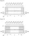
- Figure 7 is a view for explaining an arrangement state of an opening of a housing and a plurality of sensing sensors before a shield film part is installed, in one example of the present invention.
- the plurality of sensing sensors is disposed apart in a line along the longitudinal direction of the opening (111).
- the plurality of sensing sensors may be disposed apart from each other at intervals of 1/n of the length of the opening (111), and in this document, n is a natural number of 2 or more.
- the sensing sensors disposed on the left side of the center of the opening (111) are referred to as “L-sensing sensors (131 to 138)", and the sensing sensors disposed on the right side of the center of the opening (111) are referred to as “R-sensing sensors (131' to 138')”.
- each sensing sensor is numbered such that the sensor number increases from both side edges of the opening (111) toward the center of the opening (111) according to the arrangement order, whereby the sensor numbers may be stored in the control part (120).
- the "L-sensing sensors (131 to 138)” are divided and referred to as “first L-sensing sensor (131) to eighth L-sensing sensor (138)” according to the arrangement order of the sensors.
- the “R-sensing sensors (131' to 138')” are divided and referred to as “first R-sensing sensor (131') to eighth R-sensing sensor (138')” according to the arrangement order of the sensors.
- the left portion of the opening (111) may be divided into regions A1 to A8 based on the center of the opening, and the right portion may be divided into regions A'1 to A8' based on the center of the opening.
- the regions A1 to A8 and the regions A1' to A8' refer to the respective division regions.
- the virtual division region of the opening (111) is variable according to the number of installed sensing sensors. Also, the number of installed sensing sensors may be set to be equal to the number of virtual division regions.
- the first L-sensing sensor (131) is installed in the housing (110) to face the region A1 of the opening (111).
- the first L-sensing sensor (131) senses the closing of the region A1 by the shield film part (170).
- the second L-sensing sensor (132) senses the closing of the region A2 by the shield film part (170).
- the third L-sensing sensor (133) senses the closing of the region A3 by the shield film part (170).
- the fourth L-sensing sensor (134) senses the closing of the region A4 by the shield film part (170).
- the fifth L-sensing sensor (135) senses the closing of the region A5 by the shield film part (170).
- the sixth L-sensing sensor (136) senses the closing of the region A6 by the shield film part (170).
- the seventh L-sensing sensor (137) senses the closing of the region A7 by the shield film part (170).
- the eighth L-sensing sensor (138) senses the closing of the region A8 by the shield film part (170).
- the first R-sensing sensor (131') senses the closing of the region A1' by the shield film part (170).
- the second R-sensing sensor (132') senses the closing of the region A2' by the shield film part (170).
- the third R-sensing sensor (133') senses the closing of the region A3' by the shielding part (170).
- the fourth R-detecting sensor (134') senses the closing of the region A4' by the shield film part (170).
- the fifth R-sensing sensor (135') senses the closing of the region A5' by the shield film part (170).
- the sixth R-detecting sensor (136') senses the closing of the region A6' by the shield film part (170).
- the seventh R-sensor (137') senses the closing of the region A7' by the shield film part (170).
- the eighth R-sensing sensor (138') senses the closing of the region A8' by the shield film part (170).
- Figures 8 and 9 are views for explaining an operating state of a shield film part according to one example
- Figure 10 is a view for explaining an operating state of a shield film part according to another example.
- the shield film part (170) is installed in the housing (110) to open and close the opening (111) on the reference surface (112).
- the shield film part (170) is movably installed on the reference surface (112) along the longitudinal direction of the opening (111) to adjust the open area of the opening (111).
- the shield film part (170) is provided to cover a partial region or the entire region including both sides of the opening (111) in the width direction of the opening (111).
- the shield film part (170) includes a pair of guide members (177, 178), a first shield film unit (170a) and a second shield film unit (170b).
- the pair of guide members (177, 178) are disposed apart from each other side by side along the width direction of the opening (111), and each installed on the reference surface (112) along the length direction of the opening (111).
- the first shield film unit (170a) and the second shield film unit (170b) are movably installed on the pair of guide members (177, 178), respectively, and are operated to cover a partial region or the entire region of the opening (111) while moving in close directions or open directions.
- the close directions (Lc, Rc) are directions moving from the edges of the opening (111) toward the center of the opening (111).
- the open directions (Lo, Ro) are directions opposite to the close directions.
- the open directions (Lo, Ro) are directions moving from the center (o) of the opening (111) toward the edges of the opening (111).
- the first shield film unit (170a) is provided to cover one side region of the opening (111) while moving along the pair of guide members (177, 178).
- the first shield film unit (170a) opens and closes one side region of the opening (111) by control of the control part (120) while moving in the first close direction (Lc) or the first open direction (Lo) in a unit of 1/n of the opening area.
- the first shield film unit (170a) may adjust the open region of the opening (111) by control of the control part (120) while moving toward the first close direction (Lc) in a unit of 1/n of the opening area based on one side edge of the opening (111).
- the first shield film unit (170a) may adjust the open region of the opening (111) by control of the control part (120) while moving toward the first open direction (Lo) in a unit of 1/n of the opening area.
- the first shield film unit (170a) comprises a first reference bar (171a), a first shield film member (172a), and a first drive unit (173a).
- the first reference bar (171a) is installed on the reference surface (112) at one side of the opening (111).
- the first shield film member (172a) is connected to the first reference bar (171a) in a roll screen type.
- the first shield film member (172a) is provided such that one end is wound around the first reference bar (171a) and the other end is movable to the pair of guide members (177, 178). In addition, the first shield film member (172a) is operated to cover one side region of the opening (111) while moving in the close direction or the open direction according to the rotation direction of the first reference bar (171a).
- the first drive unit (173a) is coupled to the first reference bar (171a) to provide rotative force to the first reference bar (171a). According to the rotation direction of the first drive unit (173a), the first shield film member (172a) is wound around the first reference bar (171a) while moving in the first open direction (Lo), or unwound from the first reference bar (171a) while moving in the first close direction (Lc).
- the first shield film unit (170c) comprises a reference bar (171c) and a plurality of first shield film members (172c). Each of the first shield film members (172c) is provided to cover 1/n of the opening area.
- the reference bar (171c) is installed on one side of the opening (111).
- the plurality of first shield film members (172a) may have a shutter structure that is folded and unfolded in multiple stages along a pair of guide members based on the reference bar (171c).
- the first shield film member (172a) is operated to cover one side region of the opening (111) in a unit of 1/n of the opening area while moving along the pair of guide members (177, 178).
- the second shield film unit (170b) is provided to cover the other side region of the opening (111) while moving along the pair of guide members (177, 178).
- the second shield film unit (170b) opens and closes the other side region of the opening (111) by control of the control part (120) while moving in the second close direction (Rc) or the second open direction (Ro) in a unit of 1/n of the opening area.
- the second shield film unit (170b) may adjust the open region of the opening (111) by control of the control part (120) while moving toward the second close direction (Rc) in a unit of 1/n of the opening area based on one side edge of the opening (111).
- the second shield film unit (170b) may adjust the open region of the opening (111) by control of the control part (120) while moving toward the second open direction (Ro) in a unit of 1/n of the opening area.
- the second shield film unit (170b) comprises a second reference bar (171b), a second shield film member (172b), and a second drive unit (173b).
- the second reference bar (171b) is installed on the reference surface (112) at the other side of the opening (111).
- the second shield film member (172b) is connected to the second reference bar (171b) in a roll screen type.
- the second shield member (172b) is provided such that one end is wound around the second reference bar (171b) and the other end is movable to the pair of guide members (177, 178).
- the second shield member (172b) is operated to cover the other side region of the opening (111) while moving in the close direction or the open direction according to the rotation direction of the second reference bar (171b).
- the second drive unit (173b) is coupled to the second reference bar (171b) to provide rotative force to the second reference bar (171b). According to the rotation direction of the second drive unit, the second shield member (172b) is wound around the second reference bar (171b) while moving in the second open direction (Ro). Alternatively, the second shield member (172b) is unwound from the second reference bar (171b) while moving in the second close direction (Rc).
- the second shield film unit (170d) comprises a second reference bar (171d) and at least one second shield film member (172d).
- the second reference bar (171d) is installed on the other side of the opening.
- the second shield film member (172b) is provided to cover 1/n of the opening area.
- the at least one second shield film member (172d) may have a shutter structure that is folded and unfolded in multiple stages along a pair of guide members based on the second reference bar (171d).
- the second shield film member (172d) is operated to cover the other side region of the opening (111) in a unit of 1/n of the opening area while moving along the pair of guide members (177, 178).
- the dry part (150) is installed in the housing (110) so that heat (Q) can be provided to the base material (10) through the opening (111).
- a heating device capable of drying the slurry applied to the base material may be used, and for example, various types of heating devices such as hot air or infrared rays may be used as the dry part (150).
- the control part (120) controls the operation of the shield film part (170) based on the coating pattern information and the sensing information of the sensing part (130).
- the coating pattern information may comprise width information of the base material (10) and width information of the slurry (11) applied to the base material (10).
- the base material (10) means a positive or negative current collector.
- a sensor number for each sensing sensor is preset in the control part (120).
- the control part (120) obtains sensing information according to the sensor number.
- the control part (120) may calculate a close region where the shield film part (170) covers the opening (111), based on the sensing information. Then, the control part (120) may adjust the open region of the opening (111) by controlling the operation of the shield film part (170) to match the coating pattern information based on the coating pattern information and the close region calculation information.
- Figure 11 schematically illustrates coating pattern information recipes preset in a control part.
- a plurality of drying zones provided along the transport path of the base material may be classified into "first to thirteenth drying zones", and drying devices may be disposed for each drying zone.
- a close region of a drying device disposed in the relevant drying zone may be set differently for each drying zone. The close region may be adjusted by the shield film part (170).
- drying recipes according to coating pattern information for each drying zone are as follows.
- the drying recipes of the first drying zone and the second drying zone may be set such that the shield film opens the entire region of the opening (111).
- the drying recipe of the third drying zone may be set such that the first shield film unit (170a) and the second shield film unit (170b) each close one region (e.g., region A1 and region A1'), and open regions A2 to A8 and regions A2' to A8' excluding the region A1 and region A1'.
- the drying recipes of the fifth, sixth, and seventh drying zones may be set such that the first shield film unit (170a) and the second shield film unit (170b) each close two regions (e.g., region A1, region A2, region A1', and region A2'), and open regions A3 to A8, and regions A3' to A8'.
- the drying recipes of the eighth and ninth drying zones may be set such that the first shield film unit (170a) and the second shield film unit (170b) each close three regions (e.g., regions A1 to A3, and regions A1' to A3'), and open regions A4 to A8, and regions A4' to A8'.
- drying recipes of the 10th to 13th drying zones may be set such that the shield films open the entire region of the opening (111).
- the present invention can reduce the time loss of shield film replacement, and improve drying defects due to improper installation of the shield film.
- a shielding region can be automatically set according to the extent that a shield film part opens and closes an opening, a time loss of shield film replacement can be reduced, and drying defects due to improper installation of the shield film can be improved.
Landscapes
- Engineering & Computer Science (AREA)
- Mechanical Engineering (AREA)
- General Engineering & Computer Science (AREA)
- Chemical & Material Sciences (AREA)
- Microbiology (AREA)
- Life Sciences & Earth Sciences (AREA)
- Textile Engineering (AREA)
- Combustion & Propulsion (AREA)
- Manufacturing & Machinery (AREA)
- Chemical Kinetics & Catalysis (AREA)
- Electrochemistry (AREA)
- General Chemical & Material Sciences (AREA)
- Drying Of Solid Materials (AREA)
- Coating Apparatus (AREA)
- Battery Electrode And Active Subsutance (AREA)
Abstract
Description
- The present invention relates to a drying device, which relates to, particularly, a drying device with an automatically adjustable shield film, and relates to, specifically, a drying device with an automatically adjustable shield film, in which a shielding region can be automatically set according to the extent that a shield film part opens and closes an opening.
- This application claims the benefit of priority based on
Korean Patent Application No. 10-2022-0011994 dated January 27, 2022 - A secondary battery is generally composed of electrodes (positive and negative electrodes), a separator, and an electrolyte, and is manufactured through a series of steps including an electrode process, an assembly process, and an activation process. Here, the positive electrode and the negative electrode are manufactured by coating an active material-containing slurry on a current collector of a sheet, mesh, film, or foil, and the like of aluminum or copper, followed by drying.
- Meanwhile, the electrode process is also referred to as a polar plate process, which is a process of manufacturing a positive electrode and a negative electrode, which are essential components of a secondary battery. The electrode process specifically comprises a mixing process, a coating process, a rolling (calendar) process, a slitting process, and a drying process.
- The positive electrode slurry prepared in the mixing process is applied to the positive electrode current collector in the coating process. Here, the negative electrode slurry is also applied to the negative electrode current collector in the coating process. The current collector applied with the slurry is cut to meet the designed standard through the rolling process and the slitting process.
- After the slitting process, moisture in the slurry applied to each current collector is removed through the drying process before entering the assembly process. In this instance, hot air or infrared rays are mainly used to dry the coated slurry.
-
Figures 1 and 2 are views for explaining a process of drying a current collector using a drying device equipped with a shield according to the conventional technology, whereFigure 2 schematically depicts a cross-section of a state cut along the line A-A inFigure 1 . - Upon drying the current collector (10), heat (Q) is applied to the current collector (10). At this time, a drying speed difference occurs in the width direction (Wa, Wb) of the current collector (10), which is a direction perpendicular to the current collector running direction (MD). Specifically, the central portion of the current collector (10) dries later than both edges of the current collector (10), which affects production efficiency degradation and coating quality.
- Particularly, when high-temperature gas injected from a nozzle contacts the current collector (10) to evaporate a solvent, there is a problem that while the hot air flow rate at the edge of the current collector (10) is relatively faster than the hot air flow rate at the center of the current collector (10), the drying is first completed at the edges of the current collector than at the center.
- That is, due to the difference between the diffusion rate of the internal solvent and the evaporation rate of the surface to be dried, the drying degree difference of the slurry (11) in the width direction of the current collector (10) occurs at the edges of the current collector (10) and the center portion of the current collector (10). Thus, defects such as cracks occur on the surface to be dried.
- Conventionally, as shown in
Figure 1 , as the drying device (20) is provided with a detachably coupled shield (20a), the problem of hot air concentrating on the edges of the current collector (10) has been solved. - Meanwhile, depending on the coating width of the current collector (10), the use of a shield (20a) with different specifications is required. Conventionally, the shields (20a, 20b) to match each model according to the widths (Wa, Wb) of the current collector (10) are replaced and used.
- Referring to
Figure 2(a) , in order to dry the current collector (10) of Model A in which the current collector (10) has a width (Wa) of 1040mm, a shield A (20a) having the specification according to Model A is used. In this instance, the opening (21a) of the shield A (20a) has a width (W1) of 800mm. - Referring to
Figure 2(b) , as another example, in order to dry the current collector (10) of Model B in which the current collector (10) has a width (Wb) of 1140mm, a shield B (20b) having the specification according to Model B is used. In this instance, the opening (21b) of the shield B (20b) has a width (W2) of 900mm. - However, in the conventional drying device (20), when the coating width and coating pattern differences are large for each model of the current collector (10), a design change of the shielding plate is required for each model. Conventionally, the replacement of the shields (20a, 20b) is required for each model of the current collector (10).
- Upon replacing the shields (20a, 20b), the time loss occurs as the process is stopped during the replacement time, and the process instability occurs due to improper installation of the shields.
- Due to the improper installation of the shield (20a or 20b), the thermal expansion coefficients of the coated portion (11, portion where the slurry is applied) and the uncoated portion (portion where the slurry is not applied) of the current collector (10) are different from each other, so that there may be a problem of the electrode, such as wrinkles or cracks.
- The problem of the electrode, such as wrinkles or cracks, may affect the adhesion force between the slurry (11) and the current collector (10), and in this case, there may be a problem such as separation of the slurry and the current collector (10) during subsequent processes.
- Therefore, a technique capable of automatically setting the shielding region without replacing the shields (20a, 20b) is required.
- The present invention is intended to provide a drying device with an automatically adjustable shield film in which a shielding region can be automatically set according to the extent that a shield film part opens and closes an opening.
- A drying device with an automatically adjustable shield film according to one example of the present invention comprises: a housing installed on a transport path of a base material and having an opening on a reference surface facing the base material; a dry part installed in the housing to provide heat to the base material through the opening; a shield film part provided to cover a partial region of the opening and movably provided along the longitudinal direction of the opening to adjust an open area of the opening; a sensing part provided to sense a region where the shield film part covers the opening; and a control part controlling operation of the shield film part based on coating pattern information including width information of the base material and width information of a slurry applied to the base material, and sensing information of the sensing part.
- Also, the shield film part may be provided to move in a unit of 1/n (n is a natural number of 2 or more) of the opening area toward a close direction based on both edges of the opening, where the close direction may be a direction moving from the edges of the opening toward the center of the opening.
- In addition, the shield film part may be provided to move in a unit of 1/n (n is a natural number of 2 or more) of the opening area toward an open direction, where the open direction may be a direction moving from the center of the opening toward the edges of the opening.
- Furthermore, the shield film part may comprise a pair of guide members installed on the reference surface along the longitudinal direction of the opening, and a plurality of shield film units movably installed on the pair of guide members and operated to cover one region or the entire region of the opening while moving in a close direction or an open direction. In addition, the close direction may be a direction moving from the edges of the opening toward the center of the opening, and the open direction may be a direction opposite to the close direction.
- Also, the plurality of shield film units may comprise a first shield film unit covering one region of the opening while moving along the pair of guide members and a second shield film unit covering the other region of the opening while moving along the pair of guide members.
- In addition, the first shield film unit may comprise, on one side of the opening, a first reference bar installed on the reference surface, a first shield film member moving in the close direction or the open direction, wherein one end is wound around the first reference bar, and the other end is provided to be movable to the pair of guide members, along a rotation direction of the first reference bar, and a first drive unit providing rotative force to the first reference bar.
- The second shield film unit may comprise, on the other side of the opening, a second reference bar installed on the reference surface, a second shield film member moving in the close direction or the open direction, wherein one end is wound around the second reference bar, and the other end is provided to be movable to the pair of guide members, along a rotation direction of the second reference bar, and a second drive unit providing rotative force to the second reference bar.
- Also, the first shield film unit comprises a plurality of first shield film members covering 1/n (n is a natural number of 2 or more) of the opening area, where the plurality of first shield film members may be provided to be folded and unfolded in multiple stages along the pair of guide members.
- In addition, the second shield film unit comprises a plurality of second shield film members covering 1/n (n is a natural number of 2 or more) of the opening area, where the plurality of second shield film members may be provided to be folded and unfolded in multiple stages along the pair of guide members.
- Furthermore, the sensing part comprises a plurality of sensing sensors, where the plurality of sensing sensors may be disposed apart in a line along the longitudinal direction of the opening.
- Also, the plurality of sensing sensors may be disposed apart from each other at intervals of 1/n (n is a natural number of 2 or more) of the opening length.
- In addition, the plurality of sensing sensors may be disposed on an opposite surface of the housing facing the opening.
- Furthermore, the control part may calculate a close region in which the shield film part covers the opening based on the sensing information of the sensing sensor, and adjust an open region of the opening through the shield film part based on the coating pattern information.
- As described above, according to the drying device with an automatically adjustable shield film pursuant to one example of the present invention, a shielding region can be automatically set according to the extent that a shield film part opens and closes an opening, a time loss of shield film replacement can be reduced, and drying defects due to improper installation of the shield film can be improved.
-
-
Figures 1 and 2 are views for explaining a process of drying a current collector using a drying device equipped with a shield according to the conventional technology. -
Figure 3 schematically illustrates an installation state diagram of a drying device with an automatically adjustable shield film according to one example of the present invention. -
Figure 4 schematically illustrates a cross-section of a drying device with an automatically adjustable shield film taken along the B-B cross-section ofFigure 3 , andFigure 5 is a view for explaining a process of providing heat to a base material upon operation of a drying device. -
Figure 6 schematically illustrates a configuration diagram of a drying device with an automatically adjustable shield film according to one example of the present invention. -
Figure 7 is a view for explaining an arrangement state of an opening of a housing and a plurality of sensing sensors before a shield film part is installed, in one example of the present invention. -
Figures 8 and9 are views for explaining an operating state of a shield film part according to one example. -
Figure 10 is a view for explaining an operating state of a shield film part according to another example. -
Figure 11 schematically illustrates coating pattern information recipes preset in a control part. - Hereinafter, a drying device with an automatically adjustable shield film according to one example of the present invention will be described in detail with reference to the accompanying drawings.
- In addition, regardless of the reference numerals, the same or corresponding components are given by the same or similar reference numerals, and duplicate descriptions thereof will be omitted, and for convenience of explanation, the size and shape of each component as shown can be exaggerated or reduced.
-
Figure 3 schematically illustrates an installation state diagram of a drying device with an automatically adjustable shield film according to one example of the present invention,Figure 4 schematically illustrates a cross-section of a drying device with an automatically adjustable shield film taken along the B-B cross-section ofFigure 3 , andFigure 5 is a view for explaining a process of providing heat to a base material upon operation of a drying device. - In addition,
Figure 6 schematically illustrates a configuration diagram of a drying device with an automatically adjustable shield film according to one example of the present invention. - A drying device (100) with an automatically adjustable shield film according to one example of the present invention comprises a housing (110), a control part (120), a sensing part (130), a dry part (150), and a shield film part (170).
- The drying device (100) comprises a housing (110) installed on a transport path of a base material (10) and having an opening (111) on a reference surface (112) facing the base material (10), a dry part (150) installed in the housing (110) to provide heat to the base material (10) through the opening (111), a shield film part (170) provided to cover a partial region of the opening (111) and movably provided along the longitudinal direction of the opening (111) to adjust an open area of the opening (111), a sensing part (130) provided to sense a region where the shield film part (170) covers the opening (111), and a control part (120) controlling operation of the shield film part (170) based on coating pattern information including width information of the base material (10) and width information of a slurry (11) applied to the base material (10), and sensing information of the sensing part (130).
- Referring to
Figure 3 , the housing (110) is installed on the transport path (MD) of the base material (10). The housing (110) is provided with the opening (111) on the reference surface (112) facing the base material (10). The sensing part (130), the dry part (150), and the shield film part (170) are each installed inside the housing (110). - The sensing part (130) is installed on the opposite surface (114) of the housing (110). The opposing surface (114) is a surface facing the reference surface (112). The sensing part (130) may be installed, on the opposite surface (114), inside the housing (110) in the longitudinal direction of the opening (111). The sensing part (130) senses a region where the shield film part (170) covers the opening (111).
- The sensing part (130) may comprise a plurality of sensing sensors. For each sensing sensor, a sensor number may be previously set in the control part (120) according to an arrangement order.
-
Figure 7 is a view for explaining an arrangement state of an opening of a housing and a plurality of sensing sensors before a shield film part is installed, in one example of the present invention. - The plurality of sensing sensors is disposed apart in a line along the longitudinal direction of the opening (111). The plurality of sensing sensors may be disposed apart from each other at intervals of 1/n of the length of the opening (111), and in this document, n is a natural number of 2 or more.
- Referring to
Figures 4 and7 , for n sensing sensors, the sensing sensors disposed on the left side of the center of the opening (111) are referred to as "L-sensing sensors (131 to 138)", and the sensing sensors disposed on the right side of the center of the opening (111) are referred to as "R-sensing sensors (131' to 138')". - In addition, each sensing sensor is numbered such that the sensor number increases from both side edges of the opening (111) toward the center of the opening (111) according to the arrangement order, whereby the sensor numbers may be stored in the control part (120).
- For convenience of description, the "L-sensing sensors (131 to 138)" are divided and referred to as "first L-sensing sensor (131) to eighth L-sensing sensor (138)" according to the arrangement order of the sensors. Then, the "R-sensing sensors (131' to 138')" are divided and referred to as "first R-sensing sensor (131') to eighth R-sensing sensor (138')" according to the arrangement order of the sensors.
- In addition, the left portion of the opening (111) may be divided into regions A1 to A8 based on the center of the opening, and the right portion may be divided into regions A'1 to A8' based on the center of the opening.
- When the opening (111) is divided into 16 regions along the longitudinal direction of the opening (111), the regions A1 to A8 and the regions A1' to A8' refer to the respective division regions. The virtual division region of the opening (111) is variable according to the number of installed sensing sensors. Also, the number of installed sensing sensors may be set to be equal to the number of virtual division regions.
- Here, the first L-sensing sensor (131) is installed in the housing (110) to face the region A1 of the opening (111). The first L-sensing sensor (131) senses the closing of the region A1 by the shield film part (170). The second L-sensing sensor (132) senses the closing of the region A2 by the shield film part (170). The third L-sensing sensor (133) senses the closing of the region A3 by the shield film part (170). The fourth L-sensing sensor (134) senses the closing of the region A4 by the shield film part (170).
- The fifth L-sensing sensor (135) senses the closing of the region A5 by the shield film part (170). The sixth L-sensing sensor (136) senses the closing of the region A6 by the shield film part (170). The seventh L-sensing sensor (137) senses the closing of the region A7 by the shield film part (170). The eighth L-sensing sensor (138) senses the closing of the region A8 by the shield film part (170).
- The first R-sensing sensor (131') senses the closing of the region A1' by the shield film part (170). The second R-sensing sensor (132') senses the closing of the region A2' by the shield film part (170). The third R-sensing sensor (133') senses the closing of the region A3' by the shielding part (170). The fourth R-detecting sensor (134') senses the closing of the region A4' by the shield film part (170).
- The fifth R-sensing sensor (135') senses the closing of the region A5' by the shield film part (170). The sixth R-detecting sensor (136') senses the closing of the region A6' by the shield film part (170). The seventh R-sensor (137') senses the closing of the region A7' by the shield film part (170). The eighth R-sensing sensor (138') senses the closing of the region A8' by the shield film part (170).
-
Figures 8 and9 are views for explaining an operating state of a shield film part according to one example, andFigure 10 is a view for explaining an operating state of a shield film part according to another example. - The shield film part (170) is installed in the housing (110) to open and close the opening (111) on the reference surface (112). The shield film part (170) is movably installed on the reference surface (112) along the longitudinal direction of the opening (111) to adjust the open area of the opening (111). The shield film part (170) is provided to cover a partial region or the entire region including both sides of the opening (111) in the width direction of the opening (111).
- The shield film part (170) includes a pair of guide members (177, 178), a first shield film unit (170a) and a second shield film unit (170b).
- Here, the pair of guide members (177, 178) are disposed apart from each other side by side along the width direction of the opening (111), and each installed on the reference surface (112) along the length direction of the opening (111).
- The first shield film unit (170a) and the second shield film unit (170b) are movably installed on the pair of guide members (177, 178), respectively, and are operated to cover a partial region or the entire region of the opening (111) while moving in close directions or open directions.
- Here, the close directions (Lc, Rc) are directions moving from the edges of the opening (111) toward the center of the opening (111). Also, the open directions (Lo, Ro) are directions opposite to the close directions. The open directions (Lo, Ro) are directions moving from the center (o) of the opening (111) toward the edges of the opening (111).
- The first shield film unit (170a) is provided to cover one side region of the opening (111) while moving along the pair of guide members (177, 178). The first shield film unit (170a) opens and closes one side region of the opening (111) by control of the control part (120) while moving in the first close direction (Lc) or the first open direction (Lo) in a unit of 1/n of the opening area.
- Upon reduction of the open region of the opening (111), the first shield film unit (170a) may adjust the open region of the opening (111) by control of the control part (120) while moving toward the first close direction (Lc) in a unit of 1/n of the opening area based on one side edge of the opening (111).
- Then, upon expansion of the open region of the opening (111), the first shield film unit (170a) may adjust the open region of the opening (111) by control of the control part (120) while moving toward the first open direction (Lo) in a unit of 1/n of the opening area.
- For example, referring to
Figures 8 and9 , the first shield film unit (170a) comprises a first reference bar (171a), a first shield film member (172a), and a first drive unit (173a). - The first reference bar (171a) is installed on the reference surface (112) at one side of the opening (111). The first shield film member (172a) is connected to the first reference bar (171a) in a roll screen type.
- The first shield film member (172a) is provided such that one end is wound around the first reference bar (171a) and the other end is movable to the pair of guide members (177, 178). In addition, the first shield film member (172a) is operated to cover one side region of the opening (111) while moving in the close direction or the open direction according to the rotation direction of the first reference bar (171a).
- The first drive unit (173a) is coupled to the first reference bar (171a) to provide rotative force to the first reference bar (171a). According to the rotation direction of the first drive unit (173a), the first shield film member (172a) is wound around the first reference bar (171a) while moving in the first open direction (Lo), or unwound from the first reference bar (171a) while moving in the first close direction (Lc).
- As another example, referring to
Figure 10 , the first shield film unit (170c) comprises a reference bar (171c) and a plurality of first shield film members (172c). Each of the first shield film members (172c) is provided to cover 1/n of the opening area. The reference bar (171c) is installed on one side of the opening (111). - The plurality of first shield film members (172a) may have a shutter structure that is folded and unfolded in multiple stages along a pair of guide members based on the reference bar (171c). The first shield film member (172a) is operated to cover one side region of the opening (111) in a unit of 1/n of the opening area while moving along the pair of guide members (177, 178).
- The second shield film unit (170b) is provided to cover the other side region of the opening (111) while moving along the pair of guide members (177, 178). The second shield film unit (170b) opens and closes the other side region of the opening (111) by control of the control part (120) while moving in the second close direction (Rc) or the second open direction (Ro) in a unit of 1/n of the opening area.
- Upon reduction of the open region of the opening (111), the second shield film unit (170b) may adjust the open region of the opening (111) by control of the control part (120) while moving toward the second close direction (Rc) in a unit of 1/n of the opening area based on one side edge of the opening (111).
- Then, upon expansion of the open region of the opening (111), the second shield film unit (170b) may adjust the open region of the opening (111) by control of the control part (120) while moving toward the second open direction (Ro) in a unit of 1/n of the opening area.
- Referring to
Figures 8 and9 , the second shield film unit (170b) comprises a second reference bar (171b), a second shield film member (172b), and a second drive unit (173b). - The second reference bar (171b) is installed on the reference surface (112) at the other side of the opening (111). The second shield film member (172b) is connected to the second reference bar (171b) in a roll screen type.
- The second shield member (172b) is provided such that one end is wound around the second reference bar (171b) and the other end is movable to the pair of guide members (177, 178). The second shield member (172b) is operated to cover the other side region of the opening (111) while moving in the close direction or the open direction according to the rotation direction of the second reference bar (171b).
- The second drive unit (173b) is coupled to the second reference bar (171b) to provide rotative force to the second reference bar (171b). According to the rotation direction of the second drive unit, the second shield member (172b) is wound around the second reference bar (171b) while moving in the second open direction (Ro). Alternatively, the second shield member (172b) is unwound from the second reference bar (171b) while moving in the second close direction (Rc).
- As another example, referring to
Figure 10 , the second shield film unit (170d) comprises a second reference bar (171d) and at least one second shield film member (172d). The second reference bar (171d) is installed on the other side of the opening. - The second shield film member (172b) is provided to cover 1/n of the opening area. The at least one second shield film member (172d) may have a shutter structure that is folded and unfolded in multiple stages along a pair of guide members based on the second reference bar (171d).
- The second shield film member (172d) is operated to cover the other side region of the opening (111) in a unit of 1/n of the opening area while moving along the pair of guide members (177, 178).
- The dry part (150) is installed in the housing (110) so that heat (Q) can be provided to the base material (10) through the opening (111). As the dry part (150), a heating device capable of drying the slurry applied to the base material may be used, and for example, various types of heating devices such as hot air or infrared rays may be used as the dry part (150).
- The control part (120) controls the operation of the shield film part (170) based on the coating pattern information and the sensing information of the sensing part (130). The coating pattern information may comprise width information of the base material (10) and width information of the slurry (11) applied to the base material (10). In addition, in this document, the base material (10) means a positive or negative current collector.
- A sensor number for each sensing sensor is preset in the control part (120). When the close region by the shield film part is sensed by each sensing sensor, the control part (120) obtains sensing information according to the sensor number.
- The control part (120) may calculate a close region where the shield film part (170) covers the opening (111), based on the sensing information. Then, the control part (120) may adjust the open region of the opening (111) by controlling the operation of the shield film part (170) to match the coating pattern information based on the coating pattern information and the close region calculation information.
-
Figure 11 schematically illustrates coating pattern information recipes preset in a control part. - Referring to the coating pattern information of
Figure 11 , a plurality of drying zones provided along the transport path of the base material may be classified into "first to thirteenth drying zones", and drying devices may be disposed for each drying zone. In addition, a close region of a drying device disposed in the relevant drying zone may be set differently for each drying zone. The close region may be adjusted by the shield film part (170). - As one example, drying recipes according to coating pattern information for each drying zone are as follows.
- Referring to
Figure 11 , the drying recipes of the first drying zone and the second drying zone may be set such that the shield film opens the entire region of the opening (111). - The drying recipe of the third drying zone may be set such that the first shield film unit (170a) and the second shield film unit (170b) each close one region (e.g., region A1 and region A1'), and open regions A2 to A8 and regions A2' to A8' excluding the region A1 and region A1'.
- The drying recipes of the fifth, sixth, and seventh drying zones may be set such that the first shield film unit (170a) and the second shield film unit (170b) each close two regions (e.g., region A1, region A2, region A1', and region A2'), and open regions A3 to A8, and regions A3' to A8'.
- The drying recipes of the eighth and ninth drying zones may be set such that the first shield film unit (170a) and the second shield film unit (170b) each close three regions (e.g., regions A1 to A3, and regions A1' to A3'), and open regions A4 to A8, and regions A4' to A8'.
- In addition, the drying recipes of the 10th to 13th drying zones may be set such that the shield films open the entire region of the opening (111).
- Accordingly, as the shielding region is automatically set to the extent that the shield film part opens and closes the opening, the present invention can reduce the time loss of shield film replacement, and improve drying defects due to improper installation of the shield film.
- The preferred examples of the present invention as described above have been disclosed for illustrative purposes, and those skilled in the art having ordinary knowledge of the present invention will be able to make various modifications, changes, and additions within the spirit and scope of the present invention, and such modifications, changes, and additions should be regarded as falling within the scope of the following claims.
- As described above, according to the drying device with an automatically adjustable shield film pursuant to one example of the present invention, a shielding region can be automatically set according to the extent that a shield film part opens and closes an opening, a time loss of shield film replacement can be reduced, and drying defects due to improper installation of the shield film can be improved.
Claims (13)
- A drying device comprising:a housing installed on a transport path of a base material and having an opening on a reference surface facing the base material;a dry part installed in the housing to provide heat to the base material through the opening;a shield film part provided to cover a partial region of the opening and movably provided along the longitudinal direction of the opening to adjust an open area of the opening;a sensing part provided to sense a region where the shield film part covers the opening; anda control part controlling operation of the shield film part based on coating pattern information including width information of the base material and width information of a slurry applied to the base material, and sensing information of the sensing part.
- The drying device according to claim 1, whereinthe shield film part is provided to move in a unit of 1/n (n is a natural number of 2 or more) of the opening area toward a close direction based on both edges of the opening, andthe close direction is a direction moving from the edges of the opening toward the center of the opening.
- The drying device according to claim 2, whereinthe shield film part is provided to move in a unit of 1/n (n is a natural number of 2 or more) of the opening area toward an open direction, andthe open direction is a direction moving from the center of the opening toward the edges of the opening.
- The drying device according to claim 1, whereinthe shield film part comprises: a pair of guide members installed on the reference surface along the longitudinal direction of the opening; anda plurality of shield film units movably installed on the pair of guide members and operated to cover one region or the entire region of the opening while moving in a close direction or an open direction, andthe close direction is a direction moving from the edges of the opening toward the center of the opening, and the open direction is a direction opposite to the close direction.
- The drying device according to claim 4, wherein the plurality of shield film units comprises:a first shield film unit covering one region of the opening while moving along the pair of guide members; anda second shield film unit covering the other region of the opening while moving along the pair of guide members.
- The drying device according to claim 5, wherein the first shield film unit comprises:on one side of the opening, a first reference bar installed on the reference surface;a first shield film member moving in the close direction or the open direction, where one end is wound around the first reference bar, and the other end is provided to be movable to the pair of guide members, along a rotation direction of the first reference bar; anda first drive unit providing rotative force to the first reference bar.
- The drying device according to claim 5, wherein the second shield film unit comprise:on the other side of the opening, a second reference bar installed on the reference surface;a second shield film member moving in the close direction or the open direction, where one end is wound around the second reference bar, and the other end is provided to be movable to the pair of guide members, along a rotation direction of the second reference bar; anda second drive unit providing rotative force to the second reference bar.
- The drying device according to claim 5, whereinthe first shield film unit comprises a plurality of first shield film members covering 1/n (n is a natural number of 2 or more) of the opening area, andthe plurality of first shield film members is provided to be folded and unfolded in multiple stages along the pair of guide members.
- The drying device according to claim 5, whereinthe second shield film unit comprises a plurality of second shield film members covering 1/n (n is a natural number of 2 or more) of the opening area, andthe plurality of second shield film members is provided to be folded and unfolded in multiple stages along the pair of guide members.
- The drying device according to claim 1, whereinthe sensing part comprises a plurality of sensing sensors, andthe plurality of sensing sensors is disposed apart in a line along the longitudinal direction of the opening.
- The drying device according to claim 10, wherein
the plurality of sensing sensors is disposed apart from each other at intervals of 1/n (n is a natural number of 2 or more) of the opening length. - The drying device according to claim 11, wherein
the plurality of sensing sensors is disposed on an opposite surface of the housing facing the opening. - The drying device according to claim 10, wherein the control partcalculates a close region in which the shield film part covers the opening based on the sensing information of the sensing sensor, andadjusts an open region of the opening through the shield film part based on the coating pattern information.
Applications Claiming Priority (2)
| Application Number | Priority Date | Filing Date | Title |
|---|---|---|---|
| KR1020220011994A KR20230115464A (en) | 2022-01-27 | 2022-01-27 | Drying device for automatically adjusting the screen and method thereof |
| PCT/KR2023/001165 WO2023146288A1 (en) | 2022-01-27 | 2023-01-26 | Drying apparatus capable of automatically adjusting screen |
Publications (3)
| Publication Number | Publication Date |
|---|---|
| EP4322240A1 true EP4322240A1 (en) | 2024-02-14 |
| EP4322240A4 EP4322240A4 (en) | 2024-09-18 |
| EP4322240B1 EP4322240B1 (en) | 2025-08-06 |
Family
ID=87472055
Family Applications (1)
| Application Number | Title | Priority Date | Filing Date |
|---|---|---|---|
| EP23747329.3A Active EP4322240B1 (en) | 2022-01-27 | 2023-01-26 | Drying device with automatically adjustable shield film |
Country Status (8)
| Country | Link |
|---|---|
| US (1) | US20240271868A1 (en) |
| EP (1) | EP4322240B1 (en) |
| JP (1) | JP7642874B2 (en) |
| KR (1) | KR20230115464A (en) |
| CN (1) | CN117280485A (en) |
| ES (1) | ES3039140T3 (en) |
| HU (1) | HUE072612T2 (en) |
| WO (1) | WO2023146288A1 (en) |
Cited By (1)
| Publication number | Priority date | Publication date | Assignee | Title |
|---|---|---|---|---|
| WO2026037453A1 (en) * | 2024-08-12 | 2026-02-19 | Bayerische Motoren Werke Aktiengesellschaft | Method and device for drying electrode coatings |
Family Cites Families (22)
| Publication number | Priority date | Publication date | Assignee | Title |
|---|---|---|---|---|
| US3494048A (en) * | 1968-01-22 | 1970-02-10 | Fmc Corp | Web edge baffle in jet drying hood |
| JPH0886567A (en) * | 1994-09-20 | 1996-04-02 | Kobe Steel Ltd | Drying method by dryer and the same dryer |
| JPH09225372A (en) * | 1996-02-20 | 1997-09-02 | Chugai Ro Co Ltd | Apparatus for adjusting application width of die coater |
| JPH1038462A (en) * | 1996-07-24 | 1998-02-13 | Mitsubishi Electric Corp | Drying equipment |
| JP2003190859A (en) * | 2001-12-27 | 2003-07-08 | Konica Corp | Apparatus and method for coating and drying |
| JP3129765U (en) * | 2006-11-14 | 2007-03-08 | 洋一郎 山野邉 | Arbitrary adjustment of wind speed distribution / Space-saving type hot air circulation dryer |
| KR20090048233A (en) * | 2007-11-09 | 2009-05-13 | 삼성전기주식회사 | Substrate Drying Equipment |
| PL2551405T3 (en) * | 2010-03-25 | 2016-06-30 | Japan Tobacco Inc | Machine for producing low-ignition-propensity web, method for producing same, and method for producing low-ignition-propensity wrapping paper used in cigarettes |
| JP5987373B2 (en) * | 2011-03-10 | 2016-09-07 | 東レ株式会社 | Coating film drying apparatus and drying method |
| KR101475429B1 (en) * | 2012-05-15 | 2014-12-23 | 주식회사 엘지화학 | Flow Controller of Drying Oven with Automatic Air Charge for Manufacturing Secondary Battery |
| KR20160037763A (en) | 2014-09-29 | 2016-04-06 | 주식회사 엘지화학 | Method for preparing electrodes and electrodes manufactured by using same |
| JP2016150476A (en) * | 2015-02-16 | 2016-08-22 | 富士ゼロックス株式会社 | Dryer device, image formation apparatus, and drying program |
| CN206153096U (en) * | 2016-10-25 | 2017-05-10 | 宁德时代新能源科技股份有限公司 | Drying oven device of coating machine |
| WO2020053103A1 (en) * | 2018-09-13 | 2020-03-19 | Canon Production Printing Holding B.V.. | A dryer for an inkjet printer |
| KR102206057B1 (en) * | 2018-11-20 | 2021-01-20 | 주식회사 엘지화학 | An electrode rolling apparatus having a heating unit for heating a non-coated portion and Manufacturing system for an electrode comprising the same |
| KR102824103B1 (en) * | 2020-02-03 | 2025-06-23 | 주식회사 엘지에너지솔루션 | Electrode drying device and electrode drying equipment including the same |
| CN212238059U (en) * | 2020-03-20 | 2020-12-29 | 深圳市新嘉拓自动化技术有限公司 | Tuyere with adjustable effective drying width |
| KR102830277B1 (en) * | 2020-07-15 | 2025-07-04 | 주식회사 엘지에너지솔루션 | Drying apparatus and manufacturing apparatus for electrode comprising the same |
| KR20220011994A (en) | 2020-07-22 | 2022-02-03 | 심보광 | light and deodorized sleep earplugs |
| CN213078986U (en) * | 2020-08-18 | 2021-04-30 | 东莞市荣汉电子材料有限公司 | A coating machine for the production of multi-layer antistatic protective film that is easy to feed |
| CN113012917B (en) * | 2021-02-23 | 2023-06-30 | 山东电力设备有限公司 | Auxiliary fixture for bonding bar-shaped magnetic shielding of transformer and operation method |
| CN214917802U (en) * | 2021-04-01 | 2021-11-30 | 联动天翼新能源有限公司 | Drying oven air nozzle assembly for drying pole piece |
-
2022
- 2022-01-27 KR KR1020220011994A patent/KR20230115464A/en active Pending
-
2023
- 2023-01-26 EP EP23747329.3A patent/EP4322240B1/en active Active
- 2023-01-26 WO PCT/KR2023/001165 patent/WO2023146288A1/en not_active Ceased
- 2023-01-26 JP JP2023573652A patent/JP7642874B2/en active Active
- 2023-01-26 ES ES23747329T patent/ES3039140T3/en active Active
- 2023-01-26 CN CN202380011579.9A patent/CN117280485A/en active Pending
- 2023-01-26 US US18/561,902 patent/US20240271868A1/en active Pending
- 2023-01-26 HU HUE23747329A patent/HUE072612T2/en unknown
Cited By (1)
| Publication number | Priority date | Publication date | Assignee | Title |
|---|---|---|---|---|
| WO2026037453A1 (en) * | 2024-08-12 | 2026-02-19 | Bayerische Motoren Werke Aktiengesellschaft | Method and device for drying electrode coatings |
Also Published As
| Publication number | Publication date |
|---|---|
| US20240271868A1 (en) | 2024-08-15 |
| HUE072612T2 (en) | 2025-11-28 |
| KR20230115464A (en) | 2023-08-03 |
| ES3039140T3 (en) | 2025-10-17 |
| EP4322240A4 (en) | 2024-09-18 |
| WO2023146288A1 (en) | 2023-08-03 |
| JP7642874B2 (en) | 2025-03-10 |
| EP4322240B1 (en) | 2025-08-06 |
| JP2024522525A (en) | 2024-06-21 |
| CN117280485A (en) | 2023-12-22 |
Similar Documents
| Publication | Publication Date | Title |
|---|---|---|
| EP1383197B1 (en) | Secondary battery manufacturing method and manufacturing device | |
| CN107293807B (en) | winding device | |
| JP5293498B2 (en) | Web conveying apparatus and method and battery manufacturing method | |
| US20040170899A1 (en) | Secondary battery, manufacturing method for secondary battery, and manufacturing apparatus for secondary battery | |
| EP4322240B1 (en) | Drying device with automatically adjustable shield film | |
| EP4238658A1 (en) | Coating apparatus | |
| US20240383712A1 (en) | Electrode Manufacturing Apparatus | |
| US12620614B2 (en) | Roll for supporting electrode and electrode manufacturing apparatus including the same | |
| KR20180079841A (en) | Device for Drying Electrode Comprising Un-winder and Re-winder | |
| CN212695185U (en) | Pole piece rolling device | |
| US20240118028A1 (en) | Infrared Heat Source Module and Method of Manufacturing an Electrode Using the Module | |
| EP4567914A1 (en) | Drying device for manufacturing electrode | |
| KR20220009095A (en) | Drying apparatus and manufacturing apparatus for electrode comprising the same | |
| CN220277477U (en) | Alignment degree system for double-sided coating | |
| KR100646550B1 (en) | Electrode plate of secondary battery and electrode plate coating apparatus of secondary battery | |
| CN115997095B (en) | Electrode drying device | |
| KR102910529B1 (en) | Electrode drying device | |
| KR20230149718A (en) | Electrode manufacturing apparature | |
| JP2003045473A (en) | Secondary battery manufacturing method and secondary battery manufacturing device | |
| WO2025220990A1 (en) | Die coater | |
| KR20240176344A (en) | Secondary battery manufacturing device and method for manufacturing secondary battery using the same | |
| EP4737050A1 (en) | Laser notching apparatus | |
| JP5545185B2 (en) | Heat shielding device, paste-attached sheet manufacturing system, paste-attached sheet manufacturing method, and electrode plate manufacturing method | |
| CN120497264A (en) | Pole piece processing equipment, control method of pole piece processing equipment and battery production system | |
| KR20250099988A (en) | Water spray device and electrode drying device including the same |
Legal Events
| Date | Code | Title | Description |
|---|---|---|---|
| STAA | Information on the status of an ep patent application or granted ep patent |
Free format text: STATUS: THE INTERNATIONAL PUBLICATION HAS BEEN MADE |
|
| PUAI | Public reference made under article 153(3) epc to a published international application that has entered the european phase |
Free format text: ORIGINAL CODE: 0009012 |
|
| STAA | Information on the status of an ep patent application or granted ep patent |
Free format text: STATUS: REQUEST FOR EXAMINATION WAS MADE |
|
| 17P | Request for examination filed |
Effective date: 20231108 |
|
| AK | Designated contracting states |
Kind code of ref document: A1 Designated state(s): AL AT BE BG CH CY CZ DE DK EE ES FI FR GB GR HR HU IE IS IT LI LT LU LV MC ME MK MT NL NO PL PT RO RS SE SI SK SM TR |
|
| A4 | Supplementary search report drawn up and despatched |
Effective date: 20240819 |
|
| RIC1 | Information provided on ipc code assigned before grant |
Ipc: F26B 25/06 20060101ALI20240809BHEP Ipc: F26B 21/06 20060101ALI20240809BHEP Ipc: F26B 3/30 20060101ALI20240809BHEP Ipc: F26B 21/00 20060101ALI20240809BHEP Ipc: F26B 13/10 20060101ALI20240809BHEP Ipc: H01M 4/04 20060101AFI20240809BHEP |
|
| GRAP | Despatch of communication of intention to grant a patent |
Free format text: ORIGINAL CODE: EPIDOSNIGR1 |
|
| STAA | Information on the status of an ep patent application or granted ep patent |
Free format text: STATUS: GRANT OF PATENT IS INTENDED |
|
| DAV | Request for validation of the european patent (deleted) | ||
| DAX | Request for extension of the european patent (deleted) | ||
| INTG | Intention to grant announced |
Effective date: 20250403 |
|
| P01 | Opt-out of the competence of the unified patent court (upc) registered |
Free format text: CASE NUMBER: APP_21353/2025 Effective date: 20250506 |
|
| GRAS | Grant fee paid |
Free format text: ORIGINAL CODE: EPIDOSNIGR3 |
|
| GRAA | (expected) grant |
Free format text: ORIGINAL CODE: 0009210 |
|
| STAA | Information on the status of an ep patent application or granted ep patent |
Free format text: STATUS: THE PATENT HAS BEEN GRANTED |
|
| AK | Designated contracting states |
Kind code of ref document: B1 Designated state(s): AL AT BE BG CH CY CZ DE DK EE ES FI FR GB GR HR HU IE IS IT LI LT LU LV MC ME MK MT NL NO PL PT RO RS SE SI SK SM TR |
|
| REG | Reference to a national code |
Ref country code: GB Ref legal event code: FG4D |
|
| REG | Reference to a national code |
Ref country code: CH Ref legal event code: EP |
|
| REG | Reference to a national code |
Ref country code: IE Ref legal event code: FG4D |
|
| REG | Reference to a national code |
Ref country code: DE Ref legal event code: R096 Ref document number: 602023005524 Country of ref document: DE |
|
| REG | Reference to a national code |
Ref country code: ES Ref legal event code: FG2A Ref document number: 3039140 Country of ref document: ES Kind code of ref document: T3 Effective date: 20251017 |
|
| REG | Reference to a national code |
Ref country code: HU Ref legal event code: AG4A Ref document number: E072612 Country of ref document: HU |
|
| REG | Reference to a national code |
Ref country code: NL Ref legal event code: MP Effective date: 20250806 |
|
| PG25 | Lapsed in a contracting state [announced via postgrant information from national office to epo] |
Ref country code: IS Free format text: LAPSE BECAUSE OF FAILURE TO SUBMIT A TRANSLATION OF THE DESCRIPTION OR TO PAY THE FEE WITHIN THE PRESCRIBED TIME-LIMIT Effective date: 20251206 |
|
| PG25 | Lapsed in a contracting state [announced via postgrant information from national office to epo] |
Ref country code: NO Free format text: LAPSE BECAUSE OF FAILURE TO SUBMIT A TRANSLATION OF THE DESCRIPTION OR TO PAY THE FEE WITHIN THE PRESCRIBED TIME-LIMIT Effective date: 20251106 |
|
| REG | Reference to a national code |
Ref country code: LT Ref legal event code: MG9D |
|
| PG25 | Lapsed in a contracting state [announced via postgrant information from national office to epo] |
Ref country code: PT Free format text: LAPSE BECAUSE OF FAILURE TO SUBMIT A TRANSLATION OF THE DESCRIPTION OR TO PAY THE FEE WITHIN THE PRESCRIBED TIME-LIMIT Effective date: 20251209 |
|
| PG25 | Lapsed in a contracting state [announced via postgrant information from national office to epo] |
Ref country code: FI Free format text: LAPSE BECAUSE OF FAILURE TO SUBMIT A TRANSLATION OF THE DESCRIPTION OR TO PAY THE FEE WITHIN THE PRESCRIBED TIME-LIMIT Effective date: 20250806 |
|
| PG25 | Lapsed in a contracting state [announced via postgrant information from national office to epo] |
Ref country code: HR Free format text: LAPSE BECAUSE OF FAILURE TO SUBMIT A TRANSLATION OF THE DESCRIPTION OR TO PAY THE FEE WITHIN THE PRESCRIBED TIME-LIMIT Effective date: 20250806 Ref country code: NL Free format text: LAPSE BECAUSE OF FAILURE TO SUBMIT A TRANSLATION OF THE DESCRIPTION OR TO PAY THE FEE WITHIN THE PRESCRIBED TIME-LIMIT Effective date: 20250806 |
|
| PGFP | Annual fee paid to national office [announced via postgrant information from national office to epo] |
Ref country code: FR Payment date: 20251223 Year of fee payment: 4 |
|
| PG25 | Lapsed in a contracting state [announced via postgrant information from national office to epo] |
Ref country code: GR Free format text: LAPSE BECAUSE OF FAILURE TO SUBMIT A TRANSLATION OF THE DESCRIPTION OR TO PAY THE FEE WITHIN THE PRESCRIBED TIME-LIMIT Effective date: 20251107 |
|
| PGFP | Annual fee paid to national office [announced via postgrant information from national office to epo] |
Ref country code: BE Payment date: 20251229 Year of fee payment: 4 |
|
| PG25 | Lapsed in a contracting state [announced via postgrant information from national office to epo] |
Ref country code: SE Free format text: LAPSE BECAUSE OF FAILURE TO SUBMIT A TRANSLATION OF THE DESCRIPTION OR TO PAY THE FEE WITHIN THE PRESCRIBED TIME-LIMIT Effective date: 20250806 |
|
| PG25 | Lapsed in a contracting state [announced via postgrant information from national office to epo] |
Ref country code: LV Free format text: LAPSE BECAUSE OF FAILURE TO SUBMIT A TRANSLATION OF THE DESCRIPTION OR TO PAY THE FEE WITHIN THE PRESCRIBED TIME-LIMIT Effective date: 20250806 |
|
| PG25 | Lapsed in a contracting state [announced via postgrant information from national office to epo] |
Ref country code: PL Free format text: LAPSE BECAUSE OF FAILURE TO SUBMIT A TRANSLATION OF THE DESCRIPTION OR TO PAY THE FEE WITHIN THE PRESCRIBED TIME-LIMIT Effective date: 20250806 Ref country code: BG Free format text: LAPSE BECAUSE OF FAILURE TO SUBMIT A TRANSLATION OF THE DESCRIPTION OR TO PAY THE FEE WITHIN THE PRESCRIBED TIME-LIMIT Effective date: 20250806 |
|
| PG25 | Lapsed in a contracting state [announced via postgrant information from national office to epo] |
Ref country code: RS Free format text: LAPSE BECAUSE OF FAILURE TO SUBMIT A TRANSLATION OF THE DESCRIPTION OR TO PAY THE FEE WITHIN THE PRESCRIBED TIME-LIMIT Effective date: 20251106 |
|
| REG | Reference to a national code |
Ref country code: AT Ref legal event code: MK05 Ref document number: 1822999 Country of ref document: AT Kind code of ref document: T Effective date: 20250806 |
|
| PGFP | Annual fee paid to national office [announced via postgrant information from national office to epo] |
Ref country code: HU Payment date: 20260129 Year of fee payment: 4 |
|
| PG25 | Lapsed in a contracting state [announced via postgrant information from national office to epo] |
Ref country code: SM Free format text: LAPSE BECAUSE OF FAILURE TO SUBMIT A TRANSLATION OF THE DESCRIPTION OR TO PAY THE FEE WITHIN THE PRESCRIBED TIME-LIMIT Effective date: 20250806 |
|
| PGFP | Annual fee paid to national office [announced via postgrant information from national office to epo] |
Ref country code: ES Payment date: 20260212 Year of fee payment: 4 |
|
| PG25 | Lapsed in a contracting state [announced via postgrant information from national office to epo] |
Ref country code: DK Free format text: LAPSE BECAUSE OF FAILURE TO SUBMIT A TRANSLATION OF THE DESCRIPTION OR TO PAY THE FEE WITHIN THE PRESCRIBED TIME-LIMIT Effective date: 20250806 |
|
| PGFP | Annual fee paid to national office [announced via postgrant information from national office to epo] |
Ref country code: DE Payment date: 20251222 Year of fee payment: 4 |
|
| PG25 | Lapsed in a contracting state [announced via postgrant information from national office to epo] |
Ref country code: AT Free format text: LAPSE BECAUSE OF FAILURE TO SUBMIT A TRANSLATION OF THE DESCRIPTION OR TO PAY THE FEE WITHIN THE PRESCRIBED TIME-LIMIT Effective date: 20250806 |
|
| PG25 | Lapsed in a contracting state [announced via postgrant information from national office to epo] |
Ref country code: IT Free format text: LAPSE BECAUSE OF FAILURE TO SUBMIT A TRANSLATION OF THE DESCRIPTION OR TO PAY THE FEE WITHIN THE PRESCRIBED TIME-LIMIT Effective date: 20250806 |
|
| PG25 | Lapsed in a contracting state [announced via postgrant information from national office to epo] |
Ref country code: CZ Free format text: LAPSE BECAUSE OF FAILURE TO SUBMIT A TRANSLATION OF THE DESCRIPTION OR TO PAY THE FEE WITHIN THE PRESCRIBED TIME-LIMIT Effective date: 20250806 |
|
| PG25 | Lapsed in a contracting state [announced via postgrant information from national office to epo] |
Ref country code: SK Free format text: LAPSE BECAUSE OF FAILURE TO SUBMIT A TRANSLATION OF THE DESCRIPTION OR TO PAY THE FEE WITHIN THE PRESCRIBED TIME-LIMIT Effective date: 20250806 Ref country code: EE Free format text: LAPSE BECAUSE OF FAILURE TO SUBMIT A TRANSLATION OF THE DESCRIPTION OR TO PAY THE FEE WITHIN THE PRESCRIBED TIME-LIMIT Effective date: 20250806 |