EP4321436A2 - Adjustable width passenger seat - Google Patents
Adjustable width passenger seat Download PDFInfo
- Publication number
- EP4321436A2 EP4321436A2 EP23190095.2A EP23190095A EP4321436A2 EP 4321436 A2 EP4321436 A2 EP 4321436A2 EP 23190095 A EP23190095 A EP 23190095A EP 4321436 A2 EP4321436 A2 EP 4321436A2
- Authority
- EP
- European Patent Office
- Prior art keywords
- frame
- armrest
- seat
- lever
- assembly
- Prior art date
- Legal status (The legal status is an assumption and is not a legal conclusion. Google has not performed a legal analysis and makes no representation as to the accuracy of the status listed.)
- Granted
Links
Images


Classifications
-
- B—PERFORMING OPERATIONS; TRANSPORTING
- B64—AIRCRAFT; AVIATION; COSMONAUTICS
- B64D—EQUIPMENT FOR FITTING IN OR TO AIRCRAFT; FLIGHT SUITS; PARACHUTES; ARRANGEMENT OR MOUNTING OF POWER PLANTS OR PROPULSION TRANSMISSIONS IN AIRCRAFT
- B64D11/00—Passenger or crew accommodation; Flight-deck installations not otherwise provided for
- B64D11/06—Arrangements of seats, or adaptations or details specially adapted for aircraft seats
- B64D11/0639—Arrangements of seats, or adaptations or details specially adapted for aircraft seats with features for adjustment or converting of seats
- B64D11/0644—Adjustable arm rests
-
- B—PERFORMING OPERATIONS; TRANSPORTING
- B60—VEHICLES IN GENERAL
- B60N—SEATS SPECIALLY ADAPTED FOR VEHICLES; VEHICLE PASSENGER ACCOMMODATION NOT OTHERWISE PROVIDED FOR
- B60N2/00—Seats specially adapted for vehicles; Arrangement or mounting of seats in vehicles
- B60N2/75—Arm-rests
- B60N2/763—Arm-rests adjustable
- B60N2/777—Transversal adjustment
-
- B—PERFORMING OPERATIONS; TRANSPORTING
- B64—AIRCRAFT; AVIATION; COSMONAUTICS
- B64D—EQUIPMENT FOR FITTING IN OR TO AIRCRAFT; FLIGHT SUITS; PARACHUTES; ARRANGEMENT OR MOUNTING OF POWER PLANTS OR PROPULSION TRANSMISSIONS IN AIRCRAFT
- B64D11/00—Passenger or crew accommodation; Flight-deck installations not otherwise provided for
- B64D11/06—Arrangements of seats, or adaptations or details specially adapted for aircraft seats
- B64D11/0647—Seats characterised by special upholstery or cushioning features
-
- B—PERFORMING OPERATIONS; TRANSPORTING
- B64—AIRCRAFT; AVIATION; COSMONAUTICS
- B64D—EQUIPMENT FOR FITTING IN OR TO AIRCRAFT; FLIGHT SUITS; PARACHUTES; ARRANGEMENT OR MOUNTING OF POWER PLANTS OR PROPULSION TRANSMISSIONS IN AIRCRAFT
- B64D11/00—Passenger or crew accommodation; Flight-deck installations not otherwise provided for
- B64D11/06—Arrangements of seats, or adaptations or details specially adapted for aircraft seats
- B64D11/0693—Width modification of seat assemblies, e.g. for class modification
-
- B—PERFORMING OPERATIONS; TRANSPORTING
- B60—VEHICLES IN GENERAL
- B60N—SEATS SPECIALLY ADAPTED FOR VEHICLES; VEHICLE PASSENGER ACCOMMODATION NOT OTHERWISE PROVIDED FOR
- B60N2/00—Seats specially adapted for vehicles; Arrangement or mounting of seats in vehicles
- B60N2/02—Seats specially adapted for vehicles; Arrangement or mounting of seats in vehicles the seat or part thereof being movable, e.g. adjustable
- B60N2002/0288—Adjustable seat width
Definitions
- the present disclosure relates generally to passenger seats such as aircraft passenger seats, and more particularly to a width adjustable passenger seat including a seat bottom configured to adjust automatically according to the lateral armrest position.
- Passenger seats are designed according to average passenger dimensions. In the case of aircraft, passenger seats may be designed according to the 95 th percentile adult male passenger. In other words, based on a sampling of adult males, the designed seat should be able to accommodate 95% of those sampled. Assuming adult males are the largest anticipated passengers in terms of physical dimensions, smaller passengers such as the 95 th percentile female and 95 th percentile child should also fit in the designed seat. While the fit may not be optimal or ergonomic for all occupants, and even less so for those at the upper and lower ends of the range and for females and children, the intention is to design the seat for safety and reasonable comfort. Seat elements that contribute to safety and comfort include the seat bottom width, seat bottom length, backrest width, backrest height, and armrest positions, among others.
- Adjustment capabilities in economy class seats are limited by typical seat row construction and relatively short seat pitch.
- premium class seats singular seats and greater seat pitch provide opportunities for more and better adjustment capabilities.
- premium class seats may be equipped with adjustable leg rests, headrests, and backrests that recline to a steep angle, among others. Even with the multitude of currently available adjustment capabilities, there are still some seat adjustments that are not made.
- seat width is typically fixed and determined by the location of the spreaders and armrest attachment locations.
- the seat width and armrest spacing may be uncomfortable, particularly for those passengers at the limits of the seat design.
- the armrests may be positioned too wide for small body types and too narrow for large body types.
- the present disclosure is directed to passenger seat constructions in which seat elements are linked such that adjusting one seat element automatically adjusts the other seat element.
- the seat elements may include the armrests and the seat bottom cushion, wherein the width of the seat bottom cushion adjusts automatically according to the lateral armrest position.
- increasing the spacing between the armrests automatically increases the width of the seat bottom cushion, and vice versa.
- lateral armrest position may be changed using an active system that acts on the seat frame members
- seat bottom cushion width may be changed using a passive system such as an expandable bellows or the like formed in the cushion.
- the same principles may be applied to the backrest considering the width of the seat bottom and backrest cushions on aircraft passenger seats may be similarly constructed.
- Benefits of the seat adjustment mechanisms disclosed herein include, but are not limited to, the possibility for more supportive and comfortable passenger seats, the ability to accommodate a greater percentile of passengers, and an added feature for premium seating classes.
- a passenger seat including a lower frame assembly, a first lateral adjustment mechanism positioned on a first lateral side of the lower frame assembly, a first armrest mechanism positioned on an outboard lateral side of the first lateral adjustment mechanism, a second lateral adjustment mechanism positioned on a second lateral side of the lower frame assembly, and a second armrest mechanism positioned on an outboard lateral side of the second lateral adjustment mechanism.
- a cushion positioned on the lower frame assembly includes a middle portion positioned between adjustable side portions wherein, in use, the adjustable side portions are configured to automatically expand as the respective first and second armrest mechanisms are repositioned laterally outward, and automatically contract as the respective first and second armrest mechanisms are repositioned laterally inward.
- each of the first and second lateral adjustment mechanisms includes a frame, spaced first and second levers each including first and second links attached at a rotating joint, each of the first and second links configured to interact with the lower frame assembly, and a connecting frame including a first leg attached to the first lever and a second leg attached to the second lever.
- driving the connecting frame laterally outward relative to the lower frame assembly drives the frame laterally outward relative to the lower frame assembly
- driving the connecting frame laterally inward relative to the lower frame assembly drives the frame laterally inward toward the lower frame assembly.
- the frame is a vertically oriented plate and the connecting frame is oriented perpendicular to the plate.
- each of the first and second armrest mechanisms includes an armrest and at least one of a vertical armrest adjustment mechanism and a rotational armrest adjustment mechanism.
- the seat further includes at least one actuator positioned in the lower frame assembly operably coupled to the first and second lateral adjustment mechanisms.
- the adjustable side bellows are formed by material voids in the cushion.
- the adjustable bellows are pneumatically actuated and drive the armrest lateral repositioning.
- the at least one transverse frame member comprises a beam tube coupled at opposing ends to the first and second armrest mechanisms.
- an armrest mechanism attachable to a seat for laterally repositioning an armrest relative to a seat including a frame attachable to a lateral side of a seat frame, at least one lever configured to adjust lateral spacing between the frame and the seat frame, the at least one lever including spaced first and second levers attached at a rotating joint, the first and second links configured to interact with the seat frame, a connecting frame configured to couple the at least one lever to the seat frame, and an armrest assembly attached to the frame.
- the armrest assembly comprises an armrest and at least one of a vertical adjustment mechanism for vertically repositioning the armrest and a rotational adjustment mechanism for angularly repositioning the armrest.
- the frame is a vertical plate and the connecting frame is oriented perpendicular to the vertical plate.
- the at least one lever includes a first lever and a second lever spaced vertically apart
- the connecting frame includes a first leg coupled to the first lever and a second leg coupled to the second lever.
- each of the rotating joint of the first lever, the first leg, the rotating joint of the second lever, and the second leg is coupled to the frame through a vertical pivot axis formed through the frame.
- each of the first and second levers operates in a horizontal plane.
- the connecting frame and the armrest assembly are positioned on opposite sides of the vertical plate.
- Embodiments of the inventive concepts may include one or more or any combination of the above aspects, features and configurations.
- the present disclosure provides embodiments of passenger seat assemblies, for instance an aircraft passenger seat assembly, equipped with laterally repositionable armrests.
- repositioning the armrests laterally outward automatically causes the seat bottom cushion to expand through stored energy in the seat bottom cushion
- the repositioning the armrests laterally inward automatically causes the seat bottom cushion to contract through force of the armrest adjustment mechanisms against the lateral sides of the seat bottom cushion.
- the width of the armrests and the seat bottom cushion can be adjusted, in conjunction, according to the passenger preference, to tailor the seat to the size of the occupant, to change a seat size to accommodate a size change in a laterally adjacent seat, etc.
- the term “forward” may mean front or the direction of travel parallel to the aircraft longitudinal axis
- the term “lateral” may mean to the side such as perpendicular to the aircraft longitudinal axis
- the term “outward” may mean away from a longitudinal axis
- the term “inward” may mean toward a longitudinal axis.
- the seat includes a longitudinal axis and a forward end, and armrests movements are described with reference thereto such that lateral movement outward or repositioning outward may mean moving away from the seat longitudinal axis and lateral movement inward or repositioning inward may mean moving toward the seat longitudinal axis.
- the lateral armrest positions are configured to be changed from a first or contracted condition in which the armrests are positioned closer together, to a second or expanded condition in which the armrests are positioned farther apart.
- the contracted condition also referred to herein as "contracted”
- the expanded condition also referred to herein as “expanded”
- the contracted condition may accommodate the 95 th percentile occupant
- the expanded condition may accommodate occupants falling outside of the 95 th percentile or a particular seating preference of the passenger.
- a portion of the seat cushion undergoes a dimensional change with the lateral repositioning of the armrests. Specifically, at least one expandable portion of the seat cushion expands in its width dimension when the armrests are repositioned laterally outward, and contracts in its width dimension when the armrests are repositioned laterally inward.
- the construction of the cushion itself drives the width readjustment such that the readjustment happens automatically with the lateral armrest repositioning.
- stored energy in the compressed seat cushion causes expansion when the compressive force is removed when the armrests are repositioned laterally outward.
- FIGS. 1A-2B illustrate a non-limiting example of a passenger seat, for instance a premium class aircraft passenger seat 100.
- the passenger seat 100 may be mounted on a frame 102 capable of adjusting the lateral seat position. In other embodiments, the passenger seat 100 may be mounted directly to the floor.
- the passenger seat 100 generally includes a seat bottom 104, a backrest 106 including a headrest 108, a deployable leg rest 110, and left and right armrests 112.
- the passenger seat 100 may be equipped with various adjustment mechanisms including actuator driven translational and rotational mechanisms for changing sitting positions, component angles, component relationships, component performance, etc.
- the seat may adjust between an upright sitting position shown in the drawings and a bed position for sleeping, through various intermediate sitting positions.
- Frame members generally contribute to support while cushions and dress covers generally contribute to comfort. Dress covers and closeouts further contribute to the seat aesthetics.
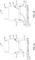
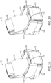
- FIGS. 1A and 2A show the "first" armrest position or seat condition in which the armrests 112 are positioned laterally inward and the seat cushion 114 contracted.
- FIGS. 1B and 2B show the "second" armrest position or seat condition in which the armrests 112 are repositioned laterally outward and the seat cushion 114 expanded.
- the seat cushion 114 is continuous from end-to-end and includes a middle portion 116 positioned between expandable side portions 118.
- the seat cushion 114 includes separate middle and side portions.
- the side portions 118 are configured to expand and contract automatically in conjunction with lateral armrest repositioning. For example, repositioning the armrests laterally inward causes an element to compress the at least one expandable cushion element, and repositioning the armrests laterally outward relaxes or removes the compressive force acting on the at least one expandable cushion element.
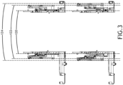
- FIG. 3 shows a comparison of the first and second lateral armrests positions.
- Reference lines 120 indicate the position of the fixed longitudinal seat frame members for a comparative reference. As used herein, the term "fixed” is with regard to the armrests and their adjustment mechanisms. It is understood that the seat may be equipped with other adjustment mechanisms configured to change the seat frame position in the aircraft or angle.
- Reference lines 122 indicate the first, normal or contracted position on the armrests.
- Reference lines 124 indicate the second, occasional or expanded position of the armrests.
- the armrests move laterally outward, independently or preferably in conjunction, from the contracted condition to the expanded condition, and laterally inward, independently or preferably in conjunction, from the expanded condition to the contracted condition.
- the difference between the first and second positions may be subtle as shown in FIG. 3 , for instance a few centimeters change, or more pronounced if desired depending on the seat construction and application.
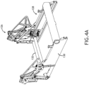
- FIG. 4A shows the seat frame assembly 126.
- the frame assembly 126 includes a lower carriage assembly 128, also referred to herein as a lower frame assembly, configured to translate forward and aft as the seat adjusts between upright and reclined.
- the lower frame assembly 128 generally includes spaced longitudinal frame members 130 interconnected through transverse frame members 132, for instance transverse beam tubes.
- the transverse frame members 132 support and maintain squareness of the lower frame assembly and further serve to attach and guide additional components as discussed further below.
- FIG. 4B shows the disassembled state of the frame assembly 126.
- the frame assembly 126 generally includes the lower carriage assembly 128, a first lateral adjustment mechanism 134 movably coupled to the first lateral side (e.g., right side) of the lower frame assembly 126, a first armrest mechanism 136 attached to an outboard lateral side of the first lateral adjustment mechanism 134, a second lateral adjustment mechanism 138 movably coupled to a second lateral side (e.g., left side) of the lower frame assembly 126, and a second armrest mechanism 140 (e.g., left side armrest) attached to an outboard lateral side of the second lateral adjustment mechanism 138.
- first lateral adjustment mechanism 134 movably coupled to the first lateral side (e.g., right side) of the lower frame assembly 126
- a first armrest mechanism 136 attached to an outboard lateral side of the first lateral adjustment mechanism 134
- a second lateral adjustment mechanism 138 movably coupled to a second lateral side (e
- the first or right-side lateral adjustment mechanism 134 operates to laterally reposition the first or right-side armrest mechanism 136
- the second or left-side lateral adjustment mechanism 138 operates to laterally reposition the second or left side armrest mechanism 140.
- the right-side armrest is carried by the right-side adjustment mechanism and the left-side armrest is carried by the left-side adjustment mechanism such that the right and left side armrests reposition laterally with their respective adjustment mechanism.
- Each armrest adjustment mechanism is couped to an armrest (see FIGS. 1A-2B ) and may include at least one of a vertical adjustment mechanism 142 and a rotational adjustment mechanism for inducing respective vertical position and angular changes in the armrest.
- FIGS. 5A and 5B show the frame assembly 126 with the lateral adjustment mechanisms 136, 138 attached to illustrate the lateral first and second positions.
- the lateral adjustment mechanisms 136, 138 are coupled to the transverse frame member 132 and move toward and apart from the fixed longitudinal frame members 130.
- the lateral adjustment mechanisms 136, 138 are driven toward and apart relative to the longitudinal frame members 130 by way of a motion driver and lever arrangement.
- FIG. 6 shows an embodiment of one of the lateral adjustment mechanisms 136.
- the mechanism generally includes a frame implemented as a vertical plate 144. Cutouts 146 formed in the plate 144 align in a vertical stack and receive levers 148 held in place using vertical pins 150.
- Each lever 148 includes a pair of links 152 attached together at a rotating joint 154.
- Each lever 148 is coupled to the plate 144 using a vertical pin 150.
- One lever is positioned above the other, for instance in a separate cutout formed in the plate, such that a vertical rotational axis extends through the height of the plate 144.
- Each lever 148 is further coupled to one end of a connecting frame 156 at its rotating joint 154.
- the connecting frame 156 is C-shaped and includes a first or top leg and a second or bottom leg.
- the top leg is associated with the top lever and the bottom leg is associated with the bottom lever in a vertical arrangement.
- the connecting frame 156 is further coupled to a motion driver, for instance a rack-and-pinion assembly 158 shown schematically in FIG. 6 , an actuator such as a linear or rotary actuator, or other mechanism for causing relative motion.
- a rack-and-pinion assembly 158 is coupled at opposing ends to the right and left connecting frames of the opposing lateral adjustment mechanisms 136, 138 such that activation of the assembly drives movement of the connecting frames in opposite directions thereby increasing or decreasing the distance between the armrests.
- driving the connecting frames 156 laterally outward relative to the frame assembly drives the frame 144 laterally outward away from the frame assembly
- driving the connecting frames 156 laterally inward relative to the frame assembly drives the frame 144 laterally inward toward the frame assembly.
- the ends of the levers 148 (shown detached in FIGS. 7A-8B and attached to the frame assembly in FIGS. 5A and 5B ) pivotally attach to the frame assembly, for instance to the longitudinal frame members.
- FIGS. 7A and 7B shown the lever ends diverged to position the frame 144 nearest the frame assembly.
- FIGS. 8A and 8B show the lever ends converged to position the frame 144 farthest the frame assembly.
- the action of the motion driver drives the motion of the connecting frame 156 and consequently the lever action.
- FIGS. 9A and 9B show cushion expansion and contraction schematically.
- the cushion includes a center portion 116 and at least one expandable side portion implemented as a bellows 160, and preferably an expandable side portion or bellows positioned on each lateral side of the center portion 116.
- the cushion may be integrally formed.
- the center and side portions may be separate.
- the cushion may be pneumatically actuated via a compressed air source.
- FIG. 9A shows air flow into and out of the expandable side portions.
- inflation of the expandable portions drives armrest positioning laterally outward while evacuation of air allows the armrests to return to their inward position, for instance via force of a return mechanism such as a return spring.
- FIGS. 10A-C show sequential cushion expansion driven by armrest repositioning.
- each side portion 116 includes voids forming a bellow.
- the material voids contract to decrease the width of the cushion.
- the material voids return to their resting state.
- the material voids are expanded.
- the lateral side of the expandable portion is coupled to the inboard side of the frame such that the cushion moves with the frame to follow and fill the formed gap.
Landscapes
- Engineering & Computer Science (AREA)
- Aviation & Aerospace Engineering (AREA)
- Transportation (AREA)
- Mechanical Engineering (AREA)
- Seats For Vehicles (AREA)
Abstract
Description
- The present disclosure relates generally to passenger seats such as aircraft passenger seats, and more particularly to a width adjustable passenger seat including a seat bottom configured to adjust automatically according to the lateral armrest position.
- Passenger seats are designed according to average passenger dimensions. In the case of aircraft, passenger seats may be designed according to the 95th percentile adult male passenger. In other words, based on a sampling of adult males, the designed seat should be able to accommodate 95% of those sampled. Assuming adult males are the largest anticipated passengers in terms of physical dimensions, smaller passengers such as the 95th percentile female and 95th percentile child should also fit in the designed seat. While the fit may not be optimal or ergonomic for all occupants, and even less so for those at the upper and lower ends of the range and for females and children, the intention is to design the seat for safety and reasonable comfort. Seat elements that contribute to safety and comfort include the seat bottom width, seat bottom length, backrest width, backrest height, and armrest positions, among others.
- Adjustment capabilities in economy class seats are limited by typical seat row construction and relatively short seat pitch. In premium class seats, singular seats and greater seat pitch provide opportunities for more and better adjustment capabilities. For example, premium class seats may be equipped with adjustable leg rests, headrests, and backrests that recline to a steep angle, among others. Even with the multitude of currently available adjustment capabilities, there are still some seat adjustments that are not made. For example, seat width is typically fixed and determined by the location of the spreaders and armrest attachment locations. For some passengers, the seat width and armrest spacing may be uncomfortable, particularly for those passengers at the limits of the seat design. For example, the armrests may be positioned too wide for small body types and too narrow for large body types.
- Therefore, what is needed are further adjustment capabilities for seats to better customize seat fit for each passenger. In addition, what is needed is a link between seat elements that works in conjunction to provide comfort and support such that adjustment of one component automatically adjusts the other component without having to adjust components separately.
- Broadly speaking, the present disclosure is directed to passenger seat constructions in which seat elements are linked such that adjusting one seat element automatically adjusts the other seat element. In embodiments, the seat elements may include the armrests and the seat bottom cushion, wherein the width of the seat bottom cushion adjusts automatically according to the lateral armrest position. In use, for example, increasing the spacing between the armrests automatically increases the width of the seat bottom cushion, and vice versa. Whereas lateral armrest position may be changed using an active system that acts on the seat frame members, seat bottom cushion width may be changed using a passive system such as an expandable bellows or the like formed in the cushion. The same principles may be applied to the backrest considering the width of the seat bottom and backrest cushions on aircraft passenger seats may be similarly constructed.
- Benefits of the seat adjustment mechanisms disclosed herein include, but are not limited to, the possibility for more supportive and comfortable passenger seats, the ability to accommodate a greater percentile of passengers, and an added feature for premium seating classes.
- To achieve the foregoing and other advantages, in a first aspect the present disclosure provides a passenger seat including a lower frame assembly, a first lateral adjustment mechanism positioned on a first lateral side of the lower frame assembly, a first armrest mechanism positioned on an outboard lateral side of the first lateral adjustment mechanism, a second lateral adjustment mechanism positioned on a second lateral side of the lower frame assembly, and a second armrest mechanism positioned on an outboard lateral side of the second lateral adjustment mechanism. A cushion positioned on the lower frame assembly includes a middle portion positioned between adjustable side portions wherein, in use, the adjustable side portions are configured to automatically expand as the respective first and second armrest mechanisms are repositioned laterally outward, and automatically contract as the respective first and second armrest mechanisms are repositioned laterally inward.
- In some embodiments, each of the first and second lateral adjustment mechanisms includes a frame, spaced first and second levers each including first and second links attached at a rotating joint, each of the first and second links configured to interact with the lower frame assembly, and a connecting frame including a first leg attached to the first lever and a second leg attached to the second lever. In use, driving the connecting frame laterally outward relative to the lower frame assembly drives the frame laterally outward relative to the lower frame assembly, and driving the connecting frame laterally inward relative to the lower frame assembly drives the frame laterally inward toward the lower frame assembly.
- In some embodiments, the frame is a vertically oriented plate and the connecting frame is oriented perpendicular to the plate.
- In some embodiments, each of the first and second armrest mechanisms includes an armrest and at least one of a vertical armrest adjustment mechanism and a rotational armrest adjustment mechanism.
- In some embodiments, the seat further includes at least one actuator positioned in the lower frame assembly operably coupled to the first and second lateral adjustment mechanisms.
- In some embodiments, the adjustable side bellows are formed by material voids in the cushion.
- In some embodiments, the adjustable bellows are pneumatically actuated and drive the armrest lateral repositioning.
- In some embodiments, the at least one transverse frame member comprises a beam tube coupled at opposing ends to the first and second armrest mechanisms.
- In a further aspect, the present disclosure provides an armrest mechanism attachable to a seat for laterally repositioning an armrest relative to a seat, including a frame attachable to a lateral side of a seat frame, at least one lever configured to adjust lateral spacing between the frame and the seat frame, the at least one lever including spaced first and second levers attached at a rotating joint, the first and second links configured to interact with the seat frame, a connecting frame configured to couple the at least one lever to the seat frame, and an armrest assembly attached to the frame.
- In some embodiments, the armrest assembly comprises an armrest and at least one of a vertical adjustment mechanism for vertically repositioning the armrest and a rotational adjustment mechanism for angularly repositioning the armrest.
- In some embodiments, the frame is a vertical plate and the connecting frame is oriented perpendicular to the vertical plate.
- In some embodiments, the at least one lever includes a first lever and a second lever spaced vertically apart, and the connecting frame includes a first leg coupled to the first lever and a second leg coupled to the second lever. In use, driving the connecting frame in a first direction causes opposing ends of each of the first and second levers to converge and driving the connecting frame in a second direction opposite the first direction causes the opposing end of each of the first and second levers to converge, wherein the opposing ends of each of the first and second levers are configured to interact with the seat frame.
- In some embodiments, each of the rotating joint of the first lever, the first leg, the rotating joint of the second lever, and the second leg is coupled to the frame through a vertical pivot axis formed through the frame.
- In some embodiments, each of the first and second levers operates in a horizontal plane.
- In some embodiments, the connecting frame and the armrest assembly are positioned on opposite sides of the vertical plate.
- Embodiments of the inventive concepts may include one or more or any combination of the above aspects, features and configurations.
- Implementations of the inventive concepts disclosed herein may be better understood when consideration is given to the following detailed description thereof. Such description makes reference to the included drawings, which are not necessarily to scale, and in which some features may be exaggerated, and some features may be omitted or may be represented schematically in the interest of clarity. Like reference numbers in the drawings may represent and refer to the same or similar element, feature, or function. In the drawings:
-
FIG. 1A is a front view of a passenger seat according to an embodiment of the present disclosure; -
FIG. 1B is a front view of the passenger seat ofFIG. 1A showing the armrests positioned laterally outward and the seat bottom cushion expanded; -
FIG. 2A is a front isometric view of the passenger seat showing the first armrest lateral position; -
FIG. 2B is a front isometric view of the passenger seat ofFIG. 2A showing the armrests positioned laterally outward; -
FIG. 3 is a comparative view of seat elements showing the first and second lateral armrests positions; -
FIG. 4A is a rear isometric view of seat frame elements; -
FIG. 4B is an exploded view of the seat frame elements ofFIG. 4A ; -
FIG. 5A is a top view of the seat frame elements showing the first armrest position; -
FIG. 5B is a top view of the seat frame elements showing the second armrest position; -
FIG. 6 is an exploded view of an armrest lateral adjustment mechanism; -
FIG. 7A is a side view of the armrest lateral adjustment mechanism ofFIG. 6 shown retracted; -
FIG. 7B is a cross sectional view ofFIG. 7A taken along line A-A; -
FIG. 8A is a side view of the armrest lateral adjustment mechanism shown expanded; -
FIG. 8B is a cross sectional view ofFIG. 8A taken along line B-B; -
FIG. 9A is a schematic diagram showing an expandable cushion element in a contracted condition; -
FIG. 9B is a schematic diagram showing the expandable cushion element in an expanded condition; and -
FIGS. 10A-C show cushion element expansion. - The description set forth below in connection with the appended drawings is intended to be a description of various, illustrative embodiments of the disclosed subject matter. Specific features and functionalities are described in connection with each illustrative embodiment; however, it will be apparent to those skilled in the art that the disclosed embodiments may be practiced without each of those specific features and functionalities. The aspects, features and functions described below in connection with one embodiment are intended to be applicable to the other embodiments described below except where expressly stated or where an aspect, feature or function is incompatible with an embodiment.
- Broadly speaking, the present disclosure provides embodiments of passenger seat assemblies, for instance an aircraft passenger seat assembly, equipped with laterally repositionable armrests. In use, repositioning the armrests laterally outward automatically causes the seat bottom cushion to expand through stored energy in the seat bottom cushion, and the repositioning the armrests laterally inward automatically causes the seat bottom cushion to contract through force of the armrest adjustment mechanisms against the lateral sides of the seat bottom cushion. As such, the width of the armrests and the seat bottom cushion can be adjusted, in conjunction, according to the passenger preference, to tailor the seat to the size of the occupant, to change a seat size to accommodate a size change in a laterally adjacent seat, etc.
- Various directional terms are used herein to describe components movement relative to the environment and to each other. For example, the term "forward" may mean front or the direction of travel parallel to the aircraft longitudinal axis, the term "lateral" may mean to the side such as perpendicular to the aircraft longitudinal axis, the term "outward" may mean away from a longitudinal axis, and the term "inward" may mean toward a longitudinal axis. For example, in the passenger seat embodiments disclosed herein the seat includes a longitudinal axis and a forward end, and armrests movements are described with reference thereto such that lateral movement outward or repositioning outward may mean moving away from the seat longitudinal axis and lateral movement inward or repositioning inward may mean moving toward the seat longitudinal axis.
- In embodiments, the lateral armrest positions are configured to be changed from a first or contracted condition in which the armrests are positioned closer together, to a second or expanded condition in which the armrests are positioned farther apart. In some embodiments, the contracted condition, also referred to herein as "contracted," may correspond to a standard or normal operating condition of the seat, whereas the expanded condition, also referred to herein as "expanded," may correspond to a non-standard or occasional operating condition of the seat. For example, the contracted condition may accommodate the 95th percentile occupant whereas the expanded condition may accommodate occupants falling outside of the 95th percentile or a particular seating preference of the passenger.
- In use, a portion of the seat cushion undergoes a dimensional change with the lateral repositioning of the armrests. Specifically, at least one expandable portion of the seat cushion expands in its width dimension when the armrests are repositioned laterally outward, and contracts in its width dimension when the armrests are repositioned laterally inward. In some embodiments, the construction of the cushion itself drives the width readjustment such that the readjustment happens automatically with the lateral armrest repositioning. In some embodiments, stored energy in the compressed seat cushion causes expansion when the compressive force is removed when the armrests are repositioned laterally outward.
-
FIGS. 1A-2B illustrate a non-limiting example of a passenger seat, for instance a premium classaircraft passenger seat 100. Thepassenger seat 100 may be mounted on aframe 102 capable of adjusting the lateral seat position. In other embodiments, thepassenger seat 100 may be mounted directly to the floor. As shown, thepassenger seat 100 generally includes aseat bottom 104, abackrest 106 including aheadrest 108, adeployable leg rest 110, and left andright armrests 112. Thepassenger seat 100 may be equipped with various adjustment mechanisms including actuator driven translational and rotational mechanisms for changing sitting positions, component angles, component relationships, component performance, etc. For example, the seat may adjust between an upright sitting position shown in the drawings and a bed position for sleeping, through various intermediate sitting positions. Frame members generally contribute to support while cushions and dress covers generally contribute to comfort. Dress covers and closeouts further contribute to the seat aesthetics. -
FIGS. 1A and2A show the "first" armrest position or seat condition in which thearmrests 112 are positioned laterally inward and theseat cushion 114 contracted.FIGS. 1B and2B show the "second" armrest position or seat condition in which thearmrests 112 are repositioned laterally outward and theseat cushion 114 expanded. In some embodiments, theseat cushion 114 is continuous from end-to-end and includes amiddle portion 116 positioned betweenexpandable side portions 118. In some embodiments, theseat cushion 114 includes separate middle and side portions. In embodiments, theside portions 118 are configured to expand and contract automatically in conjunction with lateral armrest repositioning. For example, repositioning the armrests laterally inward causes an element to compress the at least one expandable cushion element, and repositioning the armrests laterally outward relaxes or removes the compressive force acting on the at least one expandable cushion element. -
FIG. 3 shows a comparison of the first and second lateral armrests positions.Reference lines 120 indicate the position of the fixed longitudinal seat frame members for a comparative reference. As used herein, the term "fixed" is with regard to the armrests and their adjustment mechanisms. It is understood that the seat may be equipped with other adjustment mechanisms configured to change the seat frame position in the aircraft or angle.Reference lines 122 indicate the first, normal or contracted position on the armrests.Reference lines 124 indicate the second, occasional or expanded position of the armrests. In embodiments, the armrests move laterally outward, independently or preferably in conjunction, from the contracted condition to the expanded condition, and laterally inward, independently or preferably in conjunction, from the expanded condition to the contracted condition. The difference between the first and second positions may be subtle as shown inFIG. 3 , for instance a few centimeters change, or more pronounced if desired depending on the seat construction and application. -
FIG. 4A shows theseat frame assembly 126. In some embodiments, theframe assembly 126 includes alower carriage assembly 128, also referred to herein as a lower frame assembly, configured to translate forward and aft as the seat adjusts between upright and reclined. Thelower frame assembly 128 generally includes spacedlongitudinal frame members 130 interconnected throughtransverse frame members 132, for instance transverse beam tubes. Thetransverse frame members 132 support and maintain squareness of the lower frame assembly and further serve to attach and guide additional components as discussed further below. -
FIG. 4B shows the disassembled state of theframe assembly 126. Theframe assembly 126 generally includes thelower carriage assembly 128, a firstlateral adjustment mechanism 134 movably coupled to the first lateral side (e.g., right side) of thelower frame assembly 126, afirst armrest mechanism 136 attached to an outboard lateral side of the firstlateral adjustment mechanism 134, a secondlateral adjustment mechanism 138 movably coupled to a second lateral side (e.g., left side) of thelower frame assembly 126, and a second armrest mechanism 140 (e.g., left side armrest) attached to an outboard lateral side of the secondlateral adjustment mechanism 138. - In use, the first or right-side
lateral adjustment mechanism 134 operates to laterally reposition the first or right-side armrest mechanism 136, and the second or left-sidelateral adjustment mechanism 138 operates to laterally reposition the second or leftside armrest mechanism 140. The right-side armrest is carried by the right-side adjustment mechanism and the left-side armrest is carried by the left-side adjustment mechanism such that the right and left side armrests reposition laterally with their respective adjustment mechanism. Each armrest adjustment mechanism is couped to an armrest (seeFIGS. 1A-2B ) and may include at least one of avertical adjustment mechanism 142 and a rotational adjustment mechanism for inducing respective vertical position and angular changes in the armrest. -
FIGS. 5A and 5B show theframe assembly 126 with thelateral adjustment mechanisms lateral adjustment mechanisms transverse frame member 132 and move toward and apart from the fixedlongitudinal frame members 130. As discussed further below, thelateral adjustment mechanisms longitudinal frame members 130 by way of a motion driver and lever arrangement. -
FIG. 6 shows an embodiment of one of thelateral adjustment mechanisms 136. The mechanism generally includes a frame implemented as avertical plate 144.Cutouts 146 formed in theplate 144 align in a vertical stack and receivelevers 148 held in place usingvertical pins 150. Eachlever 148 includes a pair of links 152 attached together at arotating joint 154. Eachlever 148 is coupled to theplate 144 using avertical pin 150. One lever is positioned above the other, for instance in a separate cutout formed in the plate, such that a vertical rotational axis extends through the height of theplate 144. Eachlever 148 is further coupled to one end of a connectingframe 156 at itsrotating joint 154. - In some embodiments, the connecting
frame 156 is C-shaped and includes a first or top leg and a second or bottom leg. The top leg is associated with the top lever and the bottom leg is associated with the bottom lever in a vertical arrangement. The connectingframe 156 is further coupled to a motion driver, for instance a rack-and-pinion assembly 158 shown schematically inFIG. 6 , an actuator such as a linear or rotary actuator, or other mechanism for causing relative motion. In use, the rack-and-pinion assembly 158 is coupled at opposing ends to the right and left connecting frames of the opposinglateral adjustment mechanisms - Referring to
FIGS. 7A-8B , driving the connectingframes 156 laterally outward relative to the frame assembly drives theframe 144 laterally outward away from the frame assembly, and driving the connectingframes 156 laterally inward relative to the frame assembly drives theframe 144 laterally inward toward the frame assembly. The ends of the levers 148 (shown detached inFIGS. 7A-8B and attached to the frame assembly inFIGS. 5A and 5B ) pivotally attach to the frame assembly, for instance to the longitudinal frame members.FIGS. 7A and 7B shown the lever ends diverged to position theframe 144 nearest the frame assembly.FIGS. 8A and 8B show the lever ends converged to position theframe 144 farthest the frame assembly. As discussed above, the action of the motion driver drives the motion of the connectingframe 156 and consequently the lever action. -
FIGS. 9A and 9B show cushion expansion and contraction schematically. As shown, the cushion includes acenter portion 116 and at least one expandable side portion implemented as abellows 160, and preferably an expandable side portion or bellows positioned on each lateral side of thecenter portion 116. In some embodiments, the cushion may be integrally formed. In other embodiments, the center and side portions may be separate. In a particular embodiment, the cushion may be pneumatically actuated via a compressed air source.FIG. 9A shows air flow into and out of the expandable side portions. In some embodiments, inflation of the expandable portions drives armrest positioning laterally outward while evacuation of air allows the armrests to return to their inward position, for instance via force of a return mechanism such as a return spring. -
FIGS. 10A-C show sequential cushion expansion driven by armrest repositioning. As shown, eachside portion 116 includes voids forming a bellow. When compressed by the lateral adjustment mechanism as shown inFIG. 10A , for instance compressed by the frame (144 as shown inFIG. 6 ), the material voids contract to decrease the width of the cushion. When decompressed as shown inFIG. 10B , the material voids return to their resting state. When stretched, as shown inFIG. 10C , the material voids are expanded. In some embodiments, the lateral side of the expandable portion is coupled to the inboard side of the frame such that the cushion moves with the frame to follow and fill the formed gap. - While the foregoing description provides embodiments of the invention by way of example only, it is envisioned that other embodiments may perform similar functions and/or achieve similar results within the scope of the claims.
Claims (15)
- A passenger seat, comprising:a frame assembly (126) including spaced longitudinal frame members (130) and at least one transverse frame member (132);a first lateral adjustment mechanism (134) movably attached to a first lateral side of the frame assembly;a first armrest mechanism (136) positioned on an outboard lateral side of the first lateral adjustment mechanism;a second lateral adjustment mechanism (138) movably attached to a second lateral side of the frame assembly;a second armrest mechanism (140) positioned on an outboard lateral side of the second lateral adjustment mechanism; anda cushion element supported by the frame assembly, the cushion element including at least one laterally expandable portion;wherein the at least one laterally expandable portion is configured to automatically expand as the respective first and second armrest mechanisms are repositioned laterally outward, and automatically contract as the respective first and second armrest mechanisms are repositioned laterally inward.
- The passenger seat according to claim 1, wherein each of the first and second lateral adjustment mechanisms comprises:a frame (144);spaced first and second levers (148) each including first and second links (152) attached at a rotating joint (154), each of the first and second links configured to interact with the frame assembly; anda connecting frame (156) including a first leg attached to the first lever and a second leg attached to the second lever;wherein, in use, driving the connecting frame laterally outward relative to the frame assembly drives the frame laterally outward relative to the lower frame assembly, and driving the connecting frame laterally inward relative to the lower frame assembly drives the frame laterally inward toward the lower frame assembly.
- The passenger seat according to claim 2, wherein:the frame includes a vertical plate; andthe connecting frame is oriented perpendicular to the plate and is configured to be driven laterally inward or outward via a rack-and-pinion assembly.
- The passenger seat according to any preceding claim, wherein each of the first and second armrest mechanisms comprises:an armrest; andat least one of a vertical armrest adjustment mechanism and a rotational armrest adjustment mechanism.
- The passenger seat according to any preceding claim, further comprising a rack-and-pinion mechanism (158) positioned in the lower frame assembly coupled to each of the first and second lateral adjustment mechanisms.
- The passenger seat according to any preceding claim, wherein the at least one laterally expandable portion is implemented as a bellow including material voids formed in the cushion.
- The passenger seat according to any preceding claim, wherein the at least one laterally expandable portion is pneumatically actuated.
- The passenger seat according to any preceding claim, wherein the at least one transverse frame member comprises a beam tube coupled to each of the first and second armrest mechanisms.
- An armrest mechanism for laterally repositioning an armrest relative to a seat, comprising:a frame (144) movably attachable to a lateral side of a seat frame;at least one lever (148) configured to adjust lateral spacing between the frame and the seat frame, the at least one lever including spaced first and second links (152) attached at a rotating joint (154), the first and second links configured to interact with the seat frame;a connecting frame (156) configured to couple the at least one lever to the seat frame;an armrest assembly attached to the frame; anda motion driver coupled to the connecting frame operable for moving the connecting frame relative to the seat frame.
- The armrest mechanism according to claim 9, wherein the armrest assembly comprises:an armrest; andat least one of a vertical adjustment mechanism for vertically repositioning the armrest and a rotational adjustment mechanism for angularly repositioning the armrest.
- The armrest mechanism according to claim 9, wherein:the frame is a vertical plate; andthe connecting frame is oriented perpendicular to the vertical plate.
- The armrest mechanism according to claim 9, wherein:the at least one lever includes a first lever and a second lever spaced vertically apart; andthe connecting frame includes a first leg coupled to the first lever and a second leg coupled to the second lever;in use, driving the connecting frame in a first direction causes opposing ends of each of the first and second levers to converge and driving the connecting frame in a second direction opposite the first direction causes the opposing end of each of the first and second levers to converge, wherein the opposing ends of each of the first and second levers are configured to interact with the seat frame.
- The armrest mechanism according to claim 12, wherein each of the rotating joint of the first lever, the first leg, the rotating joint of the second lever, and the second leg is coupled to the frame through a vertical pivot axis formed through the frame.
- The armrest mechanism according to claim 12, wherein each of the first and second levers operates in a horizontal plane.
- The armrest mechanism according to claim 9, wherein the motion driver is a rack-and-pinion assembly (158).
Applications Claiming Priority (2)
| Application Number | Priority Date | Filing Date | Title |
|---|---|---|---|
| IN202241045427 | 2022-08-09 | ||
| US18/209,648 US12434843B2 (en) | 2022-08-09 | 2023-06-14 | Adjustable width passenger seat |
Publications (3)
| Publication Number | Publication Date |
|---|---|
| EP4321436A2 true EP4321436A2 (en) | 2024-02-14 |
| EP4321436A3 EP4321436A3 (en) | 2024-03-27 |
| EP4321436B1 EP4321436B1 (en) | 2025-11-26 |
Family
ID=87557953
Family Applications (1)
| Application Number | Title | Priority Date | Filing Date |
|---|---|---|---|
| EP23190095.2A Active EP4321436B1 (en) | 2022-08-09 | 2023-08-07 | Adjustable width passenger seat |
Country Status (1)
| Country | Link |
|---|---|
| EP (1) | EP4321436B1 (en) |
Family Cites Families (5)
| Publication number | Priority date | Publication date | Assignee | Title |
|---|---|---|---|---|
| US5104065A (en) * | 1990-02-20 | 1992-04-14 | The Boeing Company | Readily convertible aircraft passenger seats |
| GB2288728B (en) * | 1994-04-28 | 1998-05-06 | Flight Equip & Eng | Convertible aircraft passenger seating |
| EP0747286A3 (en) * | 1995-06-09 | 1998-01-21 | Aviointeriors S.P.A. | Improved mechanism for the conversion of passenger seats, particularly for aircraft |
| FR2875186B1 (en) * | 2004-09-14 | 2006-11-24 | France Design Sa | ADJUSTABLE INDIVIDUAL SEAT IN WIDTH, FOR VEHICLE |
| KR101422820B1 (en) * | 2013-08-06 | 2014-08-01 | 포레시아오토모티브시팅코리아 유한회사 | Apparatus for adjusting length of seat cushion for vehicle |
-
2023
- 2023-08-07 EP EP23190095.2A patent/EP4321436B1/en active Active
Also Published As
| Publication number | Publication date |
|---|---|
| EP4321436A3 (en) | 2024-03-27 |
| EP4321436B1 (en) | 2025-11-26 |
Similar Documents
| Publication | Publication Date | Title |
|---|---|---|
| EP3517434B1 (en) | Work-and-dine aircraft seat with tilt and shift articulation | |
| CN104080646B (en) | Tilted seat assembly | |
| US8696065B2 (en) | Adjustable headrest for an aircraft seat | |
| EP3089910B1 (en) | Aircraft seat | |
| EP3756942B1 (en) | Aircraft passenger seat with in-flight rocking motion | |
| EP2313316B1 (en) | Seat articulation mechanism | |
| US20120139300A1 (en) | Aircraft seat | |
| WO2017155069A1 (en) | Seat structure | |
| EP3715253B1 (en) | Passenger seat assembly with seat pan articulation mechanism | |
| CN111572780A (en) | Multi-position adjustable headrest assembly | |
| WO2012160443A2 (en) | Kinematic seat with elastic pivot | |
| US12434843B2 (en) | Adjustable width passenger seat | |
| EP3489078B1 (en) | A vehicle seat | |
| US10933787B2 (en) | Head restraint follower | |
| EP4321436B1 (en) | Adjustable width passenger seat | |
| US10450072B2 (en) | Seatback articulation assembly and method | |
| WO2018184660A1 (en) | A seat for a vehicle | |
| JP7423948B2 (en) | Armrest device for seating seats | |
| US12447871B2 (en) | Passenger seat with forward adjustable backrest | |
| EP4163150A1 (en) | Reclinable seat with multiple configurations | |
| US20100102608A1 (en) | Seat structure | |
| EP4282760B1 (en) | Passenger seat with forward adjustable backrest |
Legal Events
| Date | Code | Title | Description |
|---|---|---|---|
| PUAI | Public reference made under article 153(3) epc to a published international application that has entered the european phase |
Free format text: ORIGINAL CODE: 0009012 |
|
| STAA | Information on the status of an ep patent application or granted ep patent |
Free format text: STATUS: THE APPLICATION HAS BEEN PUBLISHED |
|
| AK | Designated contracting states |
Kind code of ref document: A2 Designated state(s): AL AT BE BG CH CY CZ DE DK EE ES FI FR GB GR HR HU IE IS IT LI LT LU LV MC ME MK MT NL NO PL PT RO RS SE SI SK SM TR |
|
| PUAL | Search report despatched |
Free format text: ORIGINAL CODE: 0009013 |
|
| AK | Designated contracting states |
Kind code of ref document: A3 Designated state(s): AL AT BE BG CH CY CZ DE DK EE ES FI FR GB GR HR HU IE IS IT LI LT LU LV MC ME MK MT NL NO PL PT RO RS SE SI SK SM TR |
|
| RIC1 | Information provided on ipc code assigned before grant |
Ipc: B60N 2/02 20060101ALN20240222BHEP Ipc: B60N 2/75 20180101ALI20240222BHEP Ipc: B64D 11/06 20060101AFI20240222BHEP |
|
| STAA | Information on the status of an ep patent application or granted ep patent |
Free format text: STATUS: REQUEST FOR EXAMINATION WAS MADE |
|
| 17P | Request for examination filed |
Effective date: 20240926 |
|
| RBV | Designated contracting states (corrected) |
Designated state(s): AL AT BE BG CH CY CZ DE DK EE ES FI FR GB GR HR HU IE IS IT LI LT LU LV MC ME MK MT NL NO PL PT RO RS SE SI SK SM TR |
|
| GRAP | Despatch of communication of intention to grant a patent |
Free format text: ORIGINAL CODE: EPIDOSNIGR1 |
|
| STAA | Information on the status of an ep patent application or granted ep patent |
Free format text: STATUS: GRANT OF PATENT IS INTENDED |
|
| RIC1 | Information provided on ipc code assigned before grant |
Ipc: B60N 2/02 20060101ALN20250605BHEP Ipc: B60N 2/75 20180101ALI20250605BHEP Ipc: B64D 11/06 20060101AFI20250605BHEP |
|
| INTG | Intention to grant announced |
Effective date: 20250623 |
|
| GRAS | Grant fee paid |
Free format text: ORIGINAL CODE: EPIDOSNIGR3 |
|
| GRAA | (expected) grant |
Free format text: ORIGINAL CODE: 0009210 |
|
| STAA | Information on the status of an ep patent application or granted ep patent |
Free format text: STATUS: THE PATENT HAS BEEN GRANTED |
|
| AK | Designated contracting states |
Kind code of ref document: B1 Designated state(s): AL AT BE BG CH CY CZ DE DK EE ES FI FR GB GR HR HU IE IS IT LI LT LU LV MC ME MK MT NL NO PL PT RO RS SE SI SK SM TR |
|
| REG | Reference to a national code |
Ref country code: CH Ref legal event code: F10 Free format text: ST27 STATUS EVENT CODE: U-0-0-F10-F00 (AS PROVIDED BY THE NATIONAL OFFICE) Effective date: 20251126 Ref country code: GB Ref legal event code: FG4D |
|
| REG | Reference to a national code |
Ref country code: DE Ref legal event code: R096 Ref document number: 602023008937 Country of ref document: DE |
|
| REG | Reference to a national code |
Ref country code: IE Ref legal event code: FG4D |
|
| REG | Reference to a national code |
Ref country code: NL Ref legal event code: MP Effective date: 20251126 |
|
| PG25 | Lapsed in a contracting state [announced via postgrant information from national office to epo] |
Ref country code: ES Free format text: LAPSE BECAUSE OF FAILURE TO SUBMIT A TRANSLATION OF THE DESCRIPTION OR TO PAY THE FEE WITHIN THE PRESCRIBED TIME-LIMIT Effective date: 20251126 |
|
| REG | Reference to a national code |
Ref country code: LT Ref legal event code: MG9D |
|
| PG25 | Lapsed in a contracting state [announced via postgrant information from national office to epo] |
Ref country code: NO Free format text: LAPSE BECAUSE OF FAILURE TO SUBMIT A TRANSLATION OF THE DESCRIPTION OR TO PAY THE FEE WITHIN THE PRESCRIBED TIME-LIMIT Effective date: 20260226 |
|
| PG25 | Lapsed in a contracting state [announced via postgrant information from national office to epo] |
Ref country code: FI Free format text: LAPSE BECAUSE OF FAILURE TO SUBMIT A TRANSLATION OF THE DESCRIPTION OR TO PAY THE FEE WITHIN THE PRESCRIBED TIME-LIMIT Effective date: 20251126 Ref country code: AT Free format text: LAPSE BECAUSE OF FAILURE TO SUBMIT A TRANSLATION OF THE DESCRIPTION OR TO PAY THE FEE WITHIN THE PRESCRIBED TIME-LIMIT Effective date: 20251126 Ref country code: HR Free format text: LAPSE BECAUSE OF FAILURE TO SUBMIT A TRANSLATION OF THE DESCRIPTION OR TO PAY THE FEE WITHIN THE PRESCRIBED TIME-LIMIT Effective date: 20251126 |
|
| REG | Reference to a national code |
Ref country code: AT Ref legal event code: MK05 Ref document number: 1860864 Country of ref document: AT Kind code of ref document: T Effective date: 20251126 |
|
| PG25 | Lapsed in a contracting state [announced via postgrant information from national office to epo] |
Ref country code: NL Free format text: LAPSE BECAUSE OF FAILURE TO SUBMIT A TRANSLATION OF THE DESCRIPTION OR TO PAY THE FEE WITHIN THE PRESCRIBED TIME-LIMIT Effective date: 20251126 |
|
| PG25 | Lapsed in a contracting state [announced via postgrant information from national office to epo] |
Ref country code: RS Free format text: LAPSE BECAUSE OF FAILURE TO SUBMIT A TRANSLATION OF THE DESCRIPTION OR TO PAY THE FEE WITHIN THE PRESCRIBED TIME-LIMIT Effective date: 20260226 |
|
| PG25 | Lapsed in a contracting state [announced via postgrant information from national office to epo] |
Ref country code: IS Free format text: LAPSE BECAUSE OF FAILURE TO SUBMIT A TRANSLATION OF THE DESCRIPTION OR TO PAY THE FEE WITHIN THE PRESCRIBED TIME-LIMIT Effective date: 20260326 |
|
| PG25 | Lapsed in a contracting state [announced via postgrant information from national office to epo] |
Ref country code: PT Free format text: LAPSE BECAUSE OF FAILURE TO SUBMIT A TRANSLATION OF THE DESCRIPTION OR TO PAY THE FEE WITHIN THE PRESCRIBED TIME-LIMIT Effective date: 20260326 |
|
| PG25 | Lapsed in a contracting state [announced via postgrant information from national office to epo] |
Ref country code: PL Free format text: LAPSE BECAUSE OF FAILURE TO SUBMIT A TRANSLATION OF THE DESCRIPTION OR TO PAY THE FEE WITHIN THE PRESCRIBED TIME-LIMIT Effective date: 20251126 |
|
| PG25 | Lapsed in a contracting state [announced via postgrant information from national office to epo] |
Ref country code: LV Free format text: LAPSE BECAUSE OF FAILURE TO SUBMIT A TRANSLATION OF THE DESCRIPTION OR TO PAY THE FEE WITHIN THE PRESCRIBED TIME-LIMIT Effective date: 20251126 |
|
| PG25 | Lapsed in a contracting state [announced via postgrant information from national office to epo] |
Ref country code: BG Free format text: LAPSE BECAUSE OF FAILURE TO SUBMIT A TRANSLATION OF THE DESCRIPTION OR TO PAY THE FEE WITHIN THE PRESCRIBED TIME-LIMIT Effective date: 20251126 |
|
| PG25 | Lapsed in a contracting state [announced via postgrant information from national office to epo] |
Ref country code: LT Free format text: LAPSE BECAUSE OF FAILURE TO SUBMIT A TRANSLATION OF THE DESCRIPTION OR TO PAY THE FEE WITHIN THE PRESCRIBED TIME-LIMIT Effective date: 20251126 |
|
| PG25 | Lapsed in a contracting state [announced via postgrant information from national office to epo] |
Ref country code: SM Free format text: LAPSE BECAUSE OF FAILURE TO SUBMIT A TRANSLATION OF THE DESCRIPTION OR TO PAY THE FEE WITHIN THE PRESCRIBED TIME-LIMIT Effective date: 20251126 |
|
| PG25 | Lapsed in a contracting state [announced via postgrant information from national office to epo] |
Ref country code: DK Free format text: LAPSE BECAUSE OF FAILURE TO SUBMIT A TRANSLATION OF THE DESCRIPTION OR TO PAY THE FEE WITHIN THE PRESCRIBED TIME-LIMIT Effective date: 20251126 |
|
| PG25 | Lapsed in a contracting state [announced via postgrant information from national office to epo] |
Ref country code: IT Free format text: LAPSE BECAUSE OF FAILURE TO SUBMIT A TRANSLATION OF THE DESCRIPTION OR TO PAY THE FEE WITHIN THE PRESCRIBED TIME-LIMIT Effective date: 20251126 |
|
| PG25 | Lapsed in a contracting state [announced via postgrant information from national office to epo] |
Ref country code: EE Free format text: LAPSE BECAUSE OF FAILURE TO SUBMIT A TRANSLATION OF THE DESCRIPTION OR TO PAY THE FEE WITHIN THE PRESCRIBED TIME-LIMIT Effective date: 20251126 |
|
| PG25 | Lapsed in a contracting state [announced via postgrant information from national office to epo] |
Ref country code: CZ Free format text: LAPSE BECAUSE OF FAILURE TO SUBMIT A TRANSLATION OF THE DESCRIPTION OR TO PAY THE FEE WITHIN THE PRESCRIBED TIME-LIMIT Effective date: 20251126 |
|
| PG25 | Lapsed in a contracting state [announced via postgrant information from national office to epo] |
Ref country code: SK Free format text: LAPSE BECAUSE OF FAILURE TO SUBMIT A TRANSLATION OF THE DESCRIPTION OR TO PAY THE FEE WITHIN THE PRESCRIBED TIME-LIMIT Effective date: 20251126 |
|
| PG25 | Lapsed in a contracting state [announced via postgrant information from national office to epo] |
Ref country code: SE Free format text: LAPSE BECAUSE OF FAILURE TO SUBMIT A TRANSLATION OF THE DESCRIPTION OR TO PAY THE FEE WITHIN THE PRESCRIBED TIME-LIMIT Effective date: 20251126 |