EP4321424A1 - System for distributing battery weight on a boat - Google Patents
System for distributing battery weight on a boat Download PDFInfo
- Publication number
- EP4321424A1 EP4321424A1 EP23190000.2A EP23190000A EP4321424A1 EP 4321424 A1 EP4321424 A1 EP 4321424A1 EP 23190000 A EP23190000 A EP 23190000A EP 4321424 A1 EP4321424 A1 EP 4321424A1
- Authority
- EP
- European Patent Office
- Prior art keywords
- battery pack
- boat
- guideway
- actuator
- main deck
- Prior art date
- Legal status (The legal status is an assumption and is not a legal conclusion. Google has not performed a legal analysis and makes no representation as to the accuracy of the status listed.)
- Pending
Links
Images




Classifications
-
- B—PERFORMING OPERATIONS; TRANSPORTING
- B63—SHIPS OR OTHER WATERBORNE VESSELS; RELATED EQUIPMENT
- B63B—SHIPS OR OTHER WATERBORNE VESSELS; EQUIPMENT FOR SHIPPING
- B63B39/00—Equipment to decrease pitch, roll, or like unwanted vessel movements; Apparatus for indicating vessel attitude
- B63B39/02—Equipment to decrease pitch, roll, or like unwanted vessel movements; Apparatus for indicating vessel attitude to decrease vessel movements by displacement of masses
-
- B—PERFORMING OPERATIONS; TRANSPORTING
- B60—VEHICLES IN GENERAL
- B60L—PROPULSION OF ELECTRICALLY-PROPELLED VEHICLES; SUPPLYING ELECTRIC POWER FOR AUXILIARY EQUIPMENT OF ELECTRICALLY-PROPELLED VEHICLES; ELECTRODYNAMIC BRAKE SYSTEMS FOR VEHICLES IN GENERAL; MAGNETIC SUSPENSION OR LEVITATION FOR VEHICLES; MONITORING OPERATING VARIABLES OF ELECTRICALLY-PROPELLED VEHICLES; ELECTRIC SAFETY DEVICES FOR ELECTRICALLY-PROPELLED VEHICLES
- B60L50/00—Electric propulsion with power supplied within the vehicle
- B60L50/50—Electric propulsion with power supplied within the vehicle using propulsion power supplied by batteries or fuel cells
- B60L50/60—Electric propulsion with power supplied within the vehicle using propulsion power supplied by batteries or fuel cells using power supplied by batteries
- B60L50/66—Arrangements of batteries
-
- B—PERFORMING OPERATIONS; TRANSPORTING
- B63—SHIPS OR OTHER WATERBORNE VESSELS; RELATED EQUIPMENT
- B63B—SHIPS OR OTHER WATERBORNE VESSELS; EQUIPMENT FOR SHIPPING
- B63B43/00—Improving safety of vessels, e.g. damage control, not otherwise provided for
- B63B43/02—Improving safety of vessels, e.g. damage control, not otherwise provided for reducing risk of capsizing or sinking
- B63B43/04—Improving safety of vessels, e.g. damage control, not otherwise provided for reducing risk of capsizing or sinking by improving stability
- B63B43/08—Improving safety of vessels, e.g. damage control, not otherwise provided for reducing risk of capsizing or sinking by improving stability by transfer of solid ballast
-
- G—PHYSICS
- G05—CONTROLLING; REGULATING
- G05D—SYSTEMS FOR CONTROLLING OR REGULATING NON-ELECTRIC VARIABLES
- G05D1/00—Control of position, course, altitude or attitude of land, water, air or space vehicles, e.g. using automatic pilots
- G05D1/20—Control system inputs
- G05D1/24—Arrangements for determining position or orientation
- G05D1/245—Arrangements for determining position or orientation using dead reckoning
-
- G—PHYSICS
- G05—CONTROLLING; REGULATING
- G05D—SYSTEMS FOR CONTROLLING OR REGULATING NON-ELECTRIC VARIABLES
- G05D1/00—Control of position, course, altitude or attitude of land, water, air or space vehicles, e.g. using automatic pilots
- G05D1/40—Control within particular dimensions
- G05D1/49—Control of attitude, i.e. control of roll, pitch or yaw
- G05D1/498—Control of attitude, i.e. control of roll, pitch or yaw involving adjustment of the relative position of the centre of gravity of the vehicle
-
- B—PERFORMING OPERATIONS; TRANSPORTING
- B60—VEHICLES IN GENERAL
- B60L—PROPULSION OF ELECTRICALLY-PROPELLED VEHICLES; SUPPLYING ELECTRIC POWER FOR AUXILIARY EQUIPMENT OF ELECTRICALLY-PROPELLED VEHICLES; ELECTRODYNAMIC BRAKE SYSTEMS FOR VEHICLES IN GENERAL; MAGNETIC SUSPENSION OR LEVITATION FOR VEHICLES; MONITORING OPERATING VARIABLES OF ELECTRICALLY-PROPELLED VEHICLES; ELECTRIC SAFETY DEVICES FOR ELECTRICALLY-PROPELLED VEHICLES
- B60L2200/00—Type of vehicles
- B60L2200/32—Waterborne vessels
-
- B—PERFORMING OPERATIONS; TRANSPORTING
- B63—SHIPS OR OTHER WATERBORNE VESSELS; RELATED EQUIPMENT
- B63B—SHIPS OR OTHER WATERBORNE VESSELS; EQUIPMENT FOR SHIPPING
- B63B2209/00—Energy supply or activating means
-
- B—PERFORMING OPERATIONS; TRANSPORTING
- B63—SHIPS OR OTHER WATERBORNE VESSELS; RELATED EQUIPMENT
- B63B—SHIPS OR OTHER WATERBORNE VESSELS; EQUIPMENT FOR SHIPPING
- B63B2241/00—Design characteristics
- B63B2241/20—Designs or arrangements for particular purposes not otherwise provided for in this class
- B63B2241/24—Designs or arrangements for particular purposes not otherwise provided for in this class for facilitating transport, e.g. hull shape with limited dimensions
-
- B—PERFORMING OPERATIONS; TRANSPORTING
- B63—SHIPS OR OTHER WATERBORNE VESSELS; RELATED EQUIPMENT
- B63B—SHIPS OR OTHER WATERBORNE VESSELS; EQUIPMENT FOR SHIPPING
- B63B34/00—Vessels specially adapted for water sports or leisure; Body-supporting devices specially adapted for water sports or leisure
- B63B34/70—Arrangements on vessels specially adapted for generating waves for surfing, wakeboarding or the like, e.g. ballast tanks
-
- B—PERFORMING OPERATIONS; TRANSPORTING
- B63—SHIPS OR OTHER WATERBORNE VESSELS; RELATED EQUIPMENT
- B63B—SHIPS OR OTHER WATERBORNE VESSELS; EQUIPMENT FOR SHIPPING
- B63B79/00—Monitoring properties or operating parameters of vessels in operation
- B63B79/10—Monitoring properties or operating parameters of vessels in operation using sensors, e.g. pressure sensors, strain gauges or accelerometers
-
- G—PHYSICS
- G05—CONTROLLING; REGULATING
- G05D—SYSTEMS FOR CONTROLLING OR REGULATING NON-ELECTRIC VARIABLES
- G05D2109/00—Types of controlled vehicles
- G05D2109/30—Water vehicles
- G05D2109/34—Water vehicles operating on the water surface
-
- G—PHYSICS
- G05—CONTROLLING; REGULATING
- G05D—SYSTEMS FOR CONTROLLING OR REGULATING NON-ELECTRIC VARIABLES
- G05D2111/00—Details of signals used for control of position, course, altitude or attitude of land, water, air or space vehicles
- G05D2111/50—Internal signals, i.e. from sensors located in the vehicle, e.g. from compasses or angular sensors
- G05D2111/52—Internal signals, i.e. from sensors located in the vehicle, e.g. from compasses or angular sensors generated by inertial navigation means, e.g. gyroscopes or accelerometers
-
- H—ELECTRICITY
- H01—ELECTRIC ELEMENTS
- H01M—PROCESSES OR MEANS, e.g. BATTERIES, FOR THE DIRECT CONVERSION OF CHEMICAL ENERGY INTO ELECTRICAL ENERGY
- H01M2220/00—Batteries for particular applications
- H01M2220/20—Batteries in motive systems, e.g. vehicle, ship, plane
-
- H—ELECTRICITY
- H01—ELECTRIC ELEMENTS
- H01M—PROCESSES OR MEANS, e.g. BATTERIES, FOR THE DIRECT CONVERSION OF CHEMICAL ENERGY INTO ELECTRICAL ENERGY
- H01M50/00—Constructional details or processes of manufacture of the non-active parts of electrochemical cells other than fuel cells, e.g. hybrid cells
- H01M50/20—Mountings; Secondary casings or frames; Racks, modules or packs; Suspension devices; Shock absorbers; Transport or carrying devices; Holders
-
- H—ELECTRICITY
- H01—ELECTRIC ELEMENTS
- H01M—PROCESSES OR MEANS, e.g. BATTERIES, FOR THE DIRECT CONVERSION OF CHEMICAL ENERGY INTO ELECTRICAL ENERGY
- H01M50/00—Constructional details or processes of manufacture of the non-active parts of electrochemical cells other than fuel cells, e.g. hybrid cells
- H01M50/20—Mountings; Secondary casings or frames; Racks, modules or packs; Suspension devices; Shock absorbers; Transport or carrying devices; Holders
- H01M50/249—Mountings; Secondary casings or frames; Racks, modules or packs; Suspension devices; Shock absorbers; Transport or carrying devices; Holders specially adapted for aircraft or vehicles, e.g. cars or trains
Definitions
- the present disclosure relates to boats that are equipped with electrically-powered marine propulsion devices.
- U.S. Patent Application Publication No. 2022/0328912 discloses a marine battery system configured to provide energy to a marine vessel load.
- the marine battery system includes a main enclosure body and an auxiliary enclosure body that is detachably coupled to the main enclosure body to define a sealed battery volume.
- the auxiliary enclosure body is configured to perform a pressure accommodation action responsive to an increase in a temperature within the sealed battery volume.
- the marine battery system further includes a battery disposed within the sealed battery volume.
- U.S. Patent Application Publication No. 2022/0328893 discloses a marine battery pack including an enclosure defining a cavity, a plurality of cell modules within the cavity, each comprising a plurality of battery cells, and at least one sensor configured to sense at least one of a temperature, a pressure, a presence of water, and a gas content within the cavity.
- a controller is configured to detect an event warranting decommission of the battery pack based on the temperature, the pressure, the presence of water, and/or he gas content within the cavity, and then to automatically operate a pump to intake water from outside of the enclosure and pump water through the cavity from an inlet port in the enclosure to an outlet port in the enclosure so as to cool the plurality of battery cells.
- U.S. Patent Application Publication No. 2022/0328943 discloses a marine battery pack including a battery enclosure having an exterior and an interior defining a cavity, wherein the battery enclosure is configured to protect against water ingress into the cavity.
- the marine battery pack further comprises a plurality of cell modules within the cavity, each including a plurality of battery cells, and at least one exterior sensor on the battery enclosure configured to sense at least one of an exterior temperature, an exterior pressure, and a presence of water on the exterior of the battery enclosure.
- a controller is configured to identify a water exposure event based on the at least one of the exterior temperature, the exterior pressure, and the presence of water on the exterior of the battery enclosure. A water exposure response is then generated.
- a boat comprises a main deck, a first guideway installed underthe main deck, and a first battery pack coupled to the first guideway under the main deck.
- a first actuator is configured to move the first battery pack along the first guideway so as to relocate the weight of the first battery pack under the main deck.
- a system for a boat comprises a first guideway installed under a main deck of the boat, a first battery pack coupled to the first guideway under the main deck, and a first actuator configured to move the first battery pack along the first guideway.
- a controller is electrically and/or signally coupled with the first actuator.
- a user input device is electrically and/or signally coupled with the controller. The controller is configured to control the first actuator to move the first battery pack along the first guideway in response to an input to the user input device so as to relocate the weight of the first battery pack under the main deck.
- a second guideway is installed under the main deck of the boat and a second battery pack is coupled to the second guideway.
- a second actuator is configured to move the second battery pack along the second guideway.
- the controller is configured to control the second actuator to move the second battery pack along the second guideway in response to the input to the user input device so as to relocate the weight of the second battery pack under the main deck.
- the first and second guideways and the first and second actuators are configured for movement of the respective first and second battery packs in a fore-aft direction of the boat.
- the first guideway and the first actuator are configured for movement of the first battery pack in a fore-aft direction of the boat, and the second guideway and the second actuator are configured for movement of the second battery pack in a port-starboard direction of the boat.
- the boat includes a pair of hulls supporting the main deck.
- the first guideway and first battery pack are located within a first hull of the pair of hulls.
- the second guideway and the second battery pack are located within a second hull of the pair of hulls.
- a platform is located below the main deck and a pair of hulls supports the platform.
- the first and second guideways and the first and second battery packs are located between the platform and the main deck.
- a stationary power distribution box is electrically connected to the first battery pack.
- a first electrical cable couples the first battery pack to the power distribution box, and first cable maintenance means control movement of the first electrical cable as the first battery pack moves along the first guideway.
- a user input device is electrically and/or signally coupled with the first actuator.
- the first actuator is configured to move the first battery pack along the first guideway in response to an input to the user input device.
- the boat includes a controller electrically and/or signally coupled with the user input device and with the first actuator and an attitude sensor electrically and/or signally coupled with the controller.
- the attitude sensor provides information related to an angle of the main deck with respect to a stationary plane.
- the controller is configured to control the first actuator to move the first battery pack along the first guideway in response to the input to the user input device and in response to the information from the attitude sensor.
- a step-down converter is electrically coupled between the first battery pack and the first actuator.
- the first actuator is powered by the first battery pack.
- a marine propulsion device on the boat is also powered by the first battery pack.
- the phrases “at least one of A, B, and C,” “one or more of A, B, and C,” and the like, are meant to indicate A, or B, or C, or any combination of A, B, and/or C, including combinations with multiple instances of A, B, and/or C.
- the terms “mounted,” “connected,” “linked,” “supported,” and “coupled” and variations thereof are used broadly and encompass both direct and indirect mountings, connections, supports, and couplings. Further, unless otherwise specified or limited, “connected” and “coupled” are not restricted to physical or mechanical connections or couplings.
- top,” bottom, front, “back,” “left,” “right,” “lateral” or “longitudinal” features is generally intended as a description only of the orientation of such features relative to a reference frame of a particular example or illustration.
- a “top” feature may sometimes be disposed below a “bottom” feature (and so on), in some arrangements or embodiments.
- use of the words “first,” “second”, “third,” etc. is not intended to connote priority or importance, but merely to distinguish one of several similar elements from another.
- Fig. 1 is a schematic illustration of a top view of a boat 10 having a system 12 according to the present disclosure installed thereon, while Fig. 2 is a side cross-sectional view thereof.
- the boat 10 is a wakeboat, but it could be any other type of motorboat with a monohull.
- the boat 10 comprises a main deck 14 and a first guideway 16 installed underthe main deck 14.
- a second guideway 18 is also installed under the main deck 14.
- An optional third guideway 20 may also be installed under the main deck 14.
- a first battery pack 22 is coupled to the first guideway 16 under the main deck 14, a second battery pack 24 is coupled to the second guideway 18, and an optional third battery pack 26 may be coupled to the third guideway 20.
- a first actuator 28 is configured to move the first battery pack 22 along the first guideway 16 so as to relocate the weight of the first battery pack 22 underthe main deck 14.
- a second actuator 30 is configured to move the second battery pack 24 along the second guideway 18, also to relocate the weight of the second battery pack 24 under the main deck 14.
- An optional third actuator 32 is configured to move the third battery pack 26 along the third guideway 20.
- the first and second guideways 16, 18 and the first and second actuators 28, 30 are configured for movement of the respective first and second battery packs 22, 24 in a fore-aft direction of the boat 10.
- the first and second guideways 16, 18 are installed parallel to and on either side of the fore/aft centerline of the boat 10.
- the third guideway 20 and the third actuator 32 are configured for movement of the third battery pack 26 in a port-starboard direction of the boat 10.
- the third guideway 20 is installed about halfway to a third of the way from the fore end of the boat 10 to the aft end thereof.
- Fig. 1 also shows a stationary power distribution box 34 electrically connected to the first battery pack 22, the second battery pack 24, and the third battery pack 26.
- a first electrical cable 36 couples the first battery pack 22 to the power distribution box 34.
- first cable maintenance means (to be discussed in more detail below) are provided to control movement of the first electrical cable 36 as the first battery pack 22 moves along the first guideway 16.
- a second electrical cable 38 provided with second cable maintenance means couples the second battery pack 24 to the power distribution box 34
- a third electrical cable 40 provided with third cable maintenance means couples the third battery pack 26 to the power distribution box 34.
- the power distribution box 34 handles distribution of power on the boat 10, including to devices at the helm and to electrically-powered marine propulsion devices (see 1182, Fig. 11 ) that produce thrust to propel the boat 10 through water.
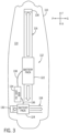
- Fig. 3 is a schematic of a top view of a boat 110 having a system 112 with a different configuration installed thereon
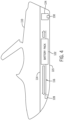
- Fig. 4 is a side cross-sectional view thereof.
- the system 112 includes a first guideway 116 installed under a main deck 114 of the boat 110, a first battery pack 122 coupled to the first guideway 116 under the main deck 114, and a first actuator 128 configured to move the first battery pack 122 along the first guideway 116.
- the system 112 also includes a second guideway 118 installed under the main deck 114, a second battery pack 124 coupled to the second guideway 118, and a second actuator 130 configured to move the second battery pack 124 along the second guideway 118.
- the first guideway 116 and the first actuator 128 are configured for movement of the first battery pack 122 in a fore-aft direction of the boat 110.
- the second guideway 118 and the second actuator 130 are configured for movement of the second battery pack 124 in a port-starboard direction of the boat 110.
- the system 112 of Figs. 3 and 4 has only two movable battery packs 122, 124.
- the first movable battery pack 122 moves along the first guideway 116, which is installed generally along the fore/aft centerline of the boat 110.
- the second movable battery pack 124 moves along the second guideway 118, which is installed at the aft end of the boat 110.
- the first battery pack 124 is coupled to a power distribution box 134 by a first electrical cable 136 provided with first cable maintenance means.
- the second battery pack 122 is coupled to the power distribution box 134 by a second electrical cable 138 provided with second cable maintenance means.
- the noted components are installed in the space between the main deck 114 and the hull 115 of the boat 110.
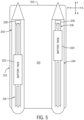
- Fig. 5 is a schematic of a top view of another type of boat 210 having a system 212 according to the present disclosure installed thereon
- Fig. 6 is a side cross-sectional view thereof.
- the system 212 includes a first guideway 116, first battery pack 222, and first actuator 228 and a second guideway 118, second battery pack 224, and second actuator 230 installed under the main deck 214.
- the first and second guideways 216, 218 and the first and second actuators 228, 230 are configured for movement of the respective first and second battery packs 222, 224 in a fore-aft direction of the boat 210, as shown by the arrows and the key.
- the boat 210 of Figs. 5 and 6 further includes a pair of hulls supporting the main deck 214.
- the boat 210 can be, for example, a pontoon, a tritoon, or a catamaran.
- the first guideway 116 and first battery pack 222 are located within a first hull 242 of the pair of hulls.
- the second guideway 218 and the second battery pack 224 are located within a second hull 244 of the pair of hulls.
- the battery packs 222, 224 move within the hollow space of the hulls 242, 244 instead of in a space between the main deck 14, 114 and the monohull 15, 115 of the boat 10, 110, as in the examples of Figs. 1-4 .
- the battery packs 222, 224 could be coupled to a power distribution box located in one of the hulls 242, 244 or on or below the main deck 214 by way of electrical cables provided with cable maintenance means.
- a power distribution box is provided in each hull 242, 244, or the battery packs 222, 224 are directly electrically connected to electrical loads such as one or more marine propulsion devices.
- Fig. 7 is a schematic of a top view of yet another boat 310 having yet another configuration of a system 312 according to the present disclosure installed thereon, and Fig. 8 is a cross-sectional side view thereof.
- the boat 310 is the same as the boat 210 in Figs. 5 and 6 , only a platform 346 is located below the main deck 314.
- the platform 346 can be connected to the main deck 314 by a series of girders, trusses, or other similar structural members.
- a pair of hulls 342, 344 support the platform 346 and are connected to the platform 346 in the manner pontoon hulls are typically connected to the main deck of a boat.
- the system 312 includes a first guideway 316, first battery pack 322, and first actuator 328 and a second guideway 318, second battery pack 324, and second actuator 330 installed under the main deck 314. More specifically, the first and second guideways 316, 318 and the first and second battery packs 322, 324 are located between the platform 346 and the main deck 314. The first and second guideways 316, 318 and the first and second actuators 328, 330 are configured for movement of the respective first and second battery packs 322, 324 in a fore-aft direction of the boat 310. An optional third guideway 320, third battery pack 326, and third actuator 332 may also be installed between the platform 346 and the main deck 314.
- the third guideway 320 and the third actuator 332 are configured for movement of the third battery pack 326 in a port-starboard direction of the boat 310.
- the example of Figs. 7 and 8 by virtue of the platform 346, allows for potentially easier construction and maintenance of the system 312, as well as provides a place to locate the third battery pack 326 and associated components.
- the platform 346 also provides a place to install a power distribution box 334 and the electrical cables 336, 338, 340 (and any associated cable maintenance means) in a protected area.
- the guideways are configured for different directions of movement.
- the guideways could extend diagonally across the boat 10.
- a guideway is installed to provide for an arcing movement of one or more battery pack(s) along the perimeter of the hull.
- Figs. 9 and 10 show different examples of guideways and actuators that can be used in the examples of Figs. 1-8 .
- Fig. 9 shows a guideway 916, which in this example comprises two pairs of vertically stacked rods 948a, 948b and 950a, 950b.
- Rod 948a is stacked above rod 948b
- rod 950a is stacked above rod 9050b.
- the upper rods 948a, 950a extend through appropriately sized holes in a respective housing 952, 954 attached to either side of the battery pack 922.
- the housings 952, 954 hold bearing packs and lead nuts that facilitate movement of the battery pack 922 along the guideway 916.
- the upper rods 948a, 950a are threaded and interact with the lead nuts such that rotation of the upper rods 948a, 950a results in translational movement of the housings 952, 954 and thus of the battery pack 922 along the rods 948a, b and 950a, b.
- the upper rods 948a, 950a are rotated by the actuator 928, which in this example comprises a servo motor 956, 958 associated with each respective rod 948a, 950a.
- the threads may have a high helix angle in order to prevent movement of the battery pack 922 when electrical power is not applied to the servo motors 956, 958.
- the lower rods 948b, 950b are not threaded, and the housings 952, 954 have appropriately sized holes that allow the housings 952, 954 to slide along the lower rods 948b, 950b.
- the lower rods 948b, 950b are optional and help support the weight of the battery pack 922.
- the lower rods 948b, 950b are the threaded drive screws, and the upper rods 948a, 950a are unthreaded.
- the housings 952, 954 are provided on the top and bottom of the battery pack 922, instead of on the lateral sides as shown in Fig. 9 .
- only one drive screw is provided centrally below the battery pack 922, which is supported by a platform above the drive screw. Additional support rods may be provided below the platform that supports the battery pack 922.
- the assembly shown in Fig. 9 could be stacked on top of another set of rods, actuators, and supports, with the lower rods extending perpendicular to the rods 948a,b and 950a,b shown in Fig. 9 and the entire assembly of Fig. 9 being moveable by the lower actuators along the lower set of rods. Such an arrangement would enable 2D planar movement of the battery pack 922 in the fore, aft, port, and starboard directions.
- each of the rods 948a, 948b and 950a, 950b can be supported by supports such as blocks, braces, brackets, or the like, and one end of each of the rods can be supported by a housing of the actuator 928.
- the supports and/or actuator can in turn be supported by the hull 15, 115 or suspended from the underside of the main deck 14, 114 in the examples of Figs. 1-4 .
- the supports and/or actuator can be supported by the inner lower surface or suspended from the inner upper surface of the hulls 242, 244 in the example of Figs. 5 and 6 .
- the supports and/or actuator can be supported by the platform 346 or suspended from the lower surface of the main deck 314 in the example of Figs. 7 and 8 .
- Fig. 10 shows an example in which the battery pack 1022 is supported by a guideway 1016 comprising two rods 1048, 1050.
- a pair of running wheels 1060, 1062 is rotatably provided on the battery pack 1022, which running wheels 1060, 1062 are supported above the rod 1048.
- a similar pair of running wheels is provided on the opposite lateral side of the battery pack 1022, above the rod 1050.
- the running wheels 1060, 1062 may be concave to prevent derailment.
- An up-stop wheel 1064 which may also be concave to prevent derailment, is also rotatably provided on the battery pack 1022, and supported below the rod 1048.
- a similar up-stop wheel is provided on the opposite lateral side of the battery pack 1022, below the rod 1050.
- the battery pack 1022 moves along the guideway 1016 by rolling of the wheels 1060, 1062, 1064 along the rods 1048, 1050. Such movement is in response to activation of the actuator 1028, which may be an electric or hydraulic linear actuator having a cylinder 1066 and a rod 1068, the latter of which is coupled to the battery pack 1022.
- the actuator 1028 which may be an electric or hydraulic linear actuator having a cylinder 1066 and a rod 1068, the latter of which is coupled to the battery pack 1022.
- side friction wheels could instead be provided on the sides of the rods 1048, 1050.
- the actuator is a rotary actuator coupled to one of the wheels 1060, 1062, 1064 on each side of the battery pack 1022, which are capable of moving the battery pack 1022 along the guideway 1016 due to friction between the driven wheels and the rods 1048, 1050.
- the linear actuator 1028 shown in Fig. 10 is not required.
- each of the rods 1048, 1050 can be supported by supports such as blocks, braces, brackets, or the like.
- the supports can in turn be supported by the hull 15, 115 or suspended from the underside of the main deck 14, 114 in the examples of Figs. 1-4 .
- the supports can be supported by the inner lower surface or suspended from the inner upper surface of the hulls 242, 244 in the example of Figs. 5 and 6 .
- the supports can be supported by the platform 346 or suspended from the lower surface of the main deck 314 in the example of Figs. 7 and 8 .
- actuators such as cogged/toothed belt drives, rack and pinion drives, or other known assemblies could be used.
- an actuator and guideways could be stacked on top of a platform that is itself movable along a guideway, in order to provide movement of a single battery pack in four directions.
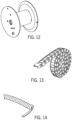
- the cable maintenance means is any assembly that controls movement of the electrical cables 36, 38, 40 136, 138, 336, 338, 340 as the battery packs to which the electrical cables are connected move along their respective guideways.
- the cable maintenance means are installed between the respective battery pack and the power distribution box 34, 134, 334.
- the cable maintenance means may be a driven or springloaded spool about which the electrical cables are wound and unwound ( Fig. 12 ), a plastic chain with a predetermined bend radius to which the electrical cable is attached ( Fig. 13 ), or a sheathing around the electrical cable that causes it to coil into a helix when tension is released ( Fig. 14 ).
- the guideways are energized or grounded and the brush of the actuator slides along the energized guideway.
- the other components associated with the battery packs and actuators can be supported in the same manner as described hereinabove, namely, supported on the upper surface of the structure below the given component and/or suspended from the lower surface of the structure above the given component.
- Fig. 11 a schematic of the electrical and/or signal connections between the components of the systems described hereinabove is provided.
- system 1112 the system will be referred to as “system 1112,” but it should be understood that this diagram applies to each of the systems 12, 112, 212, 312 described hereinabove.
- the battery packs, actuators, and power distribution box will all be labeled with a number beginning with "11,” it being understood that these elements are the same as those referred to by the same name and last two digits as the elements in Figs. 1-10 .
- the system 1112 comprises a controller 1170 electrically and/or signally coupled with the first actuator 1128 and the second actuator 1130.
- Such connection may be wired, such as by way of a direct electrical connection or a network bus, or wireless, such as by way of radio frequency communication.
- Suitable wired and wireless communication frameworks include the NMEA 2000 framework, controller area network (CAN) bus, cellular, WiFi, Bluetooth, Bluetooth Low Energy, Zigbee, or other suitable networks.
- the controller 1170 includes a processing system, a storage system accessible by the processing system, and an input/output (I/O) interface, which relays information to and from the processing system.
- I/O input/output
- the processing system can comprise a microprocessor, including a control unit and a processing unit, and other circuitry, such as semiconductor hardware logic, that retrieves and executes software from the storage system.
- the storage system can comprise any storage media readable by the processing system and capable of storing software.
- the storage system can include volatile and non-volatile, removable and non-removable media implemented in any method or technology for storage of information, such as computer-readable instructions, data structures, software modules, or other data.
- the processing system loads and executes software from the storage system, such as software programmed with one or more algorithms for relocating battery weight on the boat 10, which directs the processing system to operate as described herein below in further detail.
- the controller 1170 is (or is part of) a helm control module, a propulsion control module, or other known module for use on a boat. Note that the controller 1170 is not shown as being connected to every component in the diagrams provided herein, but the controller 1170 is in fact directly or indirectly electrically and/or signally connected to each component that it is described as controlling or from which it receives information.
- a user input device 1172 is electrically and/or signally coupled with the controller 1170.
- the user input device 1172 can be a button, a switch, a keypad, a keyboard, a touch screen, a remote control device, or another similar user input device dedicated to controlling the distribution of battery weight on the boat 10.
- the user input device may be a user's personal smart phone or tablet, which runs an application that allows the user to control the distribution of battery weight on the boat 10 via the controller 1170.
- the user input device can be wired/cabled to the controller 1170 or in wireless communication therewith.
- the controller 1070 is configured to control the first actuator 1128 to move the first battery pack 1122 along the first guideway in response to an input to the user input device 1172 so as to relocate the weight of the first battery pack 1122 under the main deck.
- the controller 1070 is also configured to control the second actuator 1130 to move the second battery pack 1124 along the second guideway in response to the input to the user input device 1172 so as to relocate the weight of the second battery pack 1124 under the main deck. If additional actuators are provided for moving battery packs on the boat, the controller 1170 is coupled to and controls those actuators as well to relocate the weight of the battery pack(s) associated therewith.
- Various options for inputs to the user input device 1172 will be described herein below.
- the system 1112 may further comprise an attitude sensor 1174 electrically and/or signally coupled with the controller 1170.
- the attitude sensor 1174 provides information related to an angle of the main deck of the boat with respect to a stationary plane.
- the attitude sensor 1174 may be an angular MEMS accelerometer; a MEMS gyrometer; an attitude and heading reference system (AHRS) that provides 3D orientation of the boat by integrating gyroscopic measurements, accelerometer data, and magnetometer data; a motion reference unit (MRU); an inertial measurement unit (IMU) or any combination of sensors capable of measuring or providing information related to pitch/roll and or trim/list of the boat 10.
- AHRS attitude and heading reference system
- MRU motion reference unit
- IMU inertial measurement unit
- the controller 1170 is configured to control the first actuator 1128 to move the first battery pack 1122 along the first guideway in response to the input to the user input device 1172 and in response to the information from the attitude sensor 1174. Similarly, the controller 1170 is configured to control the second actuator 1130 to move the second battery pack 1124 along the second guideway in response to the input to the user input device 1172 and in response to the information from the attitude sensor 1174.
- the controller 1170 is similarly configured with respect to any other movable battery packs on the boat 10.
- a speed sensor 1176 is also electrically and/or signally coupled with the controller 1170.
- the speed sensor 1176 can be a pitot tube or paddle wheel sensor measuring a speed of the boat 10 or a global positioning system receiver that calculates boat speed based on the change in GPS position over time.
- the controller 1170 may control the first and second actuators 1128, 1130 (an any other actuators for moving battery packs) in response to boat speed in combination with information from the attitude sensor 1174; boat speed in combination with input to the user input device 1172; or all three of boat speed, information from the attitude sensor 1174, and inputs to the user input device 1172.
- the user input device 1172 may be configured to provide the operator with a few or many different options for relocating the weight of one or more of the battery packs below the main deck.
- the user input device may have wakeshaping options, stability options, trailering options, efficiency options, and manual options. Each will be described in turn.
- both longitudinally movable battery packs 22, 24 122, 222, 224, 322, 324 may be moved toward the aft end of the boat 10.
- one longitudinally movable battery pack may be moved to the front or center of the boat 10, and the other longitudinally movable battery pack moved to the aft end of the boat 10.
- both longitudinally movable battery packs may be moved toward the center of the boat 10.
- Different hull configurations may require different weight distribution in order to create the desired wake shape and the above are just some examples.
- the user input device 1172 may be configured to allow the user to select which type of wake the user would like to be created.
- the controller 1170 is configured to move the battery packs as required along their respective guideways in order to achieve the selected wake shape.
- the controller 1170 may be configured to move the laterally moveable battery pack 26, 1243, 26 to the starboard side of the boat 10 to counteract the list. If the attitude sensor 1174 reports a sustained trim fore or aft, the controller 1170 may be configured to move the longitudinally movable battery packs 22, 24 122, 222, 224, 322, 324 in the opposite direction. Such relocation of battery weight might help to balance the weight of many passengers all crowded on one side or end of the boat 10 or the weight of equipment that is non-uniformly distributed on the boat 10, improving handling of the boat 10.
- the user input device 1172 may be configured with an option or options for turning on or off such stability control and/or setting the sensitivity of same (e.g., to counteract sustained list/trim or to counteract pitch/roll in real-time or somewhere in between).
- the input device 1172 may be configured to present a "trailering" option for selection by the user. If this option is selected, the battery packs may all be moved to a location where their weight would be located over the axles of a trailer. The user could program the controller 1170 to know what location along the guideways corresponds to such a position over the axles. This might allow a lesser powered truck or a car to tow a trailer with the boat 10 on it. This might also allow a vehicle with a lower tongue-weight rating to tow a trailer with the boat 10 on it because it moves the weight off the towing vehicle's chassis and onto the trailer's axles.
- Efficiency of the boat 10 in terms of electrical power required to move through the water at a given speed, may be affected by changing the boat's center of gravity as well. For instance, at low speeds, forward thrust from a rear-mounted propulsor causes bow rise, creating inefficiency and low visibility. By shifting the weight of the longitudinally movable battery packs 22, 24122, 222, 224, 322, 324 toward the bow, the center of gravity can be shifted toward the fore end of the boat 10 to counteract such bow rise.
- the controller 1170 may be configured to use information from the speed sensor 1176 to determine when the boat 10 is travelling at less than a threshold speed, below which such bow rise is more likely to occur.
- controller 1170 can use information from the attitude sensor 1174 to double-check if such bow rise is actually occurring.
- the controller 1170 can be configured to shift the weight of the longitudinally movable battery packs toward the aft end of the boat 10 as the boat picks up speed, and to stop the battery packs when the weight is more or less concentrated in the center of the boat 10. Such functionality can be turned on or off by appropriate selection via the user input device 1172.
- the weight of the battery packs can be relocated manually via the user input device 1172.
- the user input device 1172 can still be coupled to the controller 1170, which then controls the actuators 1128, 1130 to move the battery packs 1122, 1124.
- the user input device 1172 can be directly electrically and/or signally coupled with the first actuator 1128 and/or the second actuator 1130, and the first and/or second actuator 1128, 1130 is configured to move the first and/or second battery pack 1122, 1124 along the respective first and/or second guideway in response to an input to the user input device 1172.
- the user input device 1172 may simply be a first switch that provides power to the motor of the first actuator 1128 to move the first battery pack 1122 in one direction or the other and a second switch that provides power to the motor of the second actuator 1130 to move the second battery pack 1124 in one direction or the other.
- the controller 1170 would not be required.
- the system 1112 further comprises a step-down converter 1178 electrically coupled between the first battery pack 1122 and the first actuator 1128 and a step-down converter 1180 electrically coupled between the second battery pack 1124 and the second actuator 1130.
- a step-down converter 1178 electrically coupled between the first battery pack 1122 and the first actuator 1128
- a step-down converter 1180 electrically coupled between the second battery pack 1124 and the second actuator 1130.
- This allows the high-voltage battery packs 1122, 1124 to provide power to the first and second actuators 1128, 1130.
- one step-down converter coupled to one of the battery packs 1122 or 1124 powers both the first and second actuators 1128, 1130.
- a separate battery or other type of power source is provided for the first and second actuators 1128, 1130.
- a marine propulsion device 1182 such as an electric outboard motor, an electric stern drive, an electric pod drive, or the like, is also provided on the boat 10.
- the primary purpose of the battery packs 1122, 1124 is to power the marine propulsion device 1182 (of which there may be more than one) and other high-voltage loads on the boat 10.
- the step-down converters 1178, 1180 not only is the marine propulsion device 1182 on the boat powered by the first battery pack 1122, but also the first actuator 1128 is powered by the first battery pack 1122 (and same for the second actuator and second battery pack).
Landscapes
- Engineering & Computer Science (AREA)
- Mechanical Engineering (AREA)
- Chemical & Material Sciences (AREA)
- Combustion & Propulsion (AREA)
- Ocean & Marine Engineering (AREA)
- Physics & Mathematics (AREA)
- Radar, Positioning & Navigation (AREA)
- Remote Sensing (AREA)
- Aviation & Aerospace Engineering (AREA)
- General Physics & Mathematics (AREA)
- Automation & Control Theory (AREA)
- Life Sciences & Earth Sciences (AREA)
- Sustainable Development (AREA)
- Sustainable Energy (AREA)
- Power Engineering (AREA)
- Transportation (AREA)
- Battery Mounting, Suspending (AREA)
- Charge And Discharge Circuits For Batteries Or The Like (AREA)
Abstract
Description
- The present disclosure relates to boats that are equipped with electrically-powered marine propulsion devices.
-
U.S. Patent Application Publication No. 2022/0328912 , discloses a marine battery system configured to provide energy to a marine vessel load. The marine battery system includes a main enclosure body and an auxiliary enclosure body that is detachably coupled to the main enclosure body to define a sealed battery volume. The auxiliary enclosure body is configured to perform a pressure accommodation action responsive to an increase in a temperature within the sealed battery volume. The marine battery system further includes a battery disposed within the sealed battery volume. -
U.S. Patent Application Publication No. 2022/0328893 , discloses a marine battery pack including an enclosure defining a cavity, a plurality of cell modules within the cavity, each comprising a plurality of battery cells, and at least one sensor configured to sense at least one of a temperature, a pressure, a presence of water, and a gas content within the cavity. A controller is configured to detect an event warranting decommission of the battery pack based on the temperature, the pressure, the presence of water, and/or he gas content within the cavity, and then to automatically operate a pump to intake water from outside of the enclosure and pump water through the cavity from an inlet port in the enclosure to an outlet port in the enclosure so as to cool the plurality of battery cells. -
U.S. Patent Application Publication No. 2022/0328943 , discloses a marine battery pack including a battery enclosure having an exterior and an interior defining a cavity, wherein the battery enclosure is configured to protect against water ingress into the cavity. The marine battery pack further comprises a plurality of cell modules within the cavity, each including a plurality of battery cells, and at least one exterior sensor on the battery enclosure configured to sense at least one of an exterior temperature, an exterior pressure, and a presence of water on the exterior of the battery enclosure. A controller is configured to identify a water exposure event based on the at least one of the exterior temperature, the exterior pressure, and the presence of water on the exterior of the battery enclosure. A water exposure response is then generated. - This Summary is provided to introduce a selection of concepts that are further described below in the Detailed Description. This Summary is not intended to identify key or essential features of the claimed subject matter, nor is it intended to be used as an aid in limiting the scope of the claimed subject matter. The invention is defined by the independent claim. The dependent claims define advantageous embodiments.
- According to one example of the present disclosure, a boat comprises a main deck, a first guideway installed underthe main deck, and a first battery pack coupled to the first guideway under the main deck. A first actuator is configured to move the first battery pack along the first guideway so as to relocate the weight of the first battery pack under the main deck.
- According to another example of the present disclosure, a system for a boat comprises a first guideway installed under a main deck of the boat, a first battery pack coupled to the first guideway under the main deck, and a first actuator configured to move the first battery pack along the first guideway. A controller is electrically and/or signally coupled with the first actuator. A user input device is electrically and/or signally coupled with the controller. The controller is configured to control the first actuator to move the first battery pack along the first guideway in response to an input to the user input device so as to relocate the weight of the first battery pack under the main deck.
- In one example of the boat and system therefor, a second guideway is installed under the main deck of the boat and a second battery pack is coupled to the second guideway. A second actuator is configured to move the second battery pack along the second guideway. In an example of a system including a controller, the controller is configured to control the second actuator to move the second battery pack along the second guideway in response to the input to the user input device so as to relocate the weight of the second battery pack under the main deck.
- In one example of the boat and system therefor, the first and second guideways and the first and second actuators are configured for movement of the respective first and second battery packs in a fore-aft direction of the boat.
- In another example of the boat and system therefor, the first guideway and the first actuator are configured for movement of the first battery pack in a fore-aft direction of the boat, and the second guideway and the second actuator are configured for movement of the second battery pack in a port-starboard direction of the boat.
- In one example of the boat and system therefor, the boat includes a pair of hulls supporting the main deck. The first guideway and first battery pack are located within a first hull of the pair of hulls. The second guideway and the second battery pack are located within a second hull of the pair of hulls.
- In another example of the boat and system therefor, a platform is located below the main deck and a pair of hulls supports the platform. The first and second guideways and the first and second battery packs are located between the platform and the main deck.
- In one example of the boat and system therefor, a stationary power distribution box is electrically connected to the first battery pack. A first electrical cable couples the first battery pack to the power distribution box, and first cable maintenance means control movement of the first electrical cable as the first battery pack moves along the first guideway.
- In one example of the boat and system therefor, a user input device is electrically and/or signally coupled with the first actuator. The first actuator is configured to move the first battery pack along the first guideway in response to an input to the user input device.
- In one example of the boat and system therefor, the boat includes a controller electrically and/or signally coupled with the user input device and with the first actuator and an attitude sensor electrically and/or signally coupled with the controller. The attitude sensor provides information related to an angle of the main deck with respect to a stationary plane. The controller is configured to control the first actuator to move the first battery pack along the first guideway in response to the input to the user input device and in response to the information from the attitude sensor.
- In one example of the boat and system therefor, a step-down converter is electrically coupled between the first battery pack and the first actuator. The first actuator is powered by the first battery pack. A marine propulsion device on the boat is also powered by the first battery pack.
- The present disclosure is described with reference to the following Figures. The same numbers are used throughout the Figures to reference like features and like components.
-
Fig. 1 is a schematic of a top view of a boat having a system according to the present disclosure installed thereon, the system including three battery packs below a deck of the boat. -
Fig. 2 is a schematic of a cross-sectional side view of the boat ofFig. 1 . -
Fig. 3 is a schematic of a top view of a boat having a system according to the present disclosure installed thereon, the system having a different configuration with two battery packs below the deck of the boat. -
Fig. 4 is a schematic of a cross-sectional side view of the boat ofFig. 3 . -
Fig. 5 is a schematic of a top view of another type of boat having a system according to the present disclosure installed thereon, the system including two battery packs, each installed in a respective hull supporting the boat. -
Fig. 6 is a schematic of a cross-sectional side view of the boat ofFig. 5 . -
Fig. 7 is a schematic of a top view of yet another boat having yet another configuration of a system according to the present disclosure installed thereon, the system being installed on a platform located between the deck of the boat and the hulls supporting the boat. -
Fig. 8 is a schematic of a cross-sectional side view of the boat ofFig. 7 . -
Fig. 9 is a schematic of one example of an assembly of a battery pack, actuator, and guideway according to the present disclosure. -
Fig. 10 is a schematic of another example of an assembly of a battery pack, actuator, and guideway according to the present disclosure -
Fig. 11 is a schematic of a system for relocating battery packs on a boat. -
Figs. 12-14 show examples of cable maintenance means according to the present disclosure. - Before any embodiments of the invention are explained in detail, it is to be understood that the invention is not limited in its application to the details of construction and the arrangement of components set forth in the following description or illustrated in the following drawings. The invention is capable of other embodiments and of being practiced or of being carried out in various ways. Also, it is to be understood that the phraseology and terminology used herein is for the purpose of description and should not be regarded as limiting. The use of "including," "comprising," or "having" and variations thereof herein is meant to encompass the items listed thereafter and equivalents thereof as well as additional items.
- Unless otherwise specified or limited, the phrases "at least one of A, B, and C," "one or more of A, B, and C," and the like, are meant to indicate A, or B, or C, or any combination of A, B, and/or C, including combinations with multiple instances of A, B, and/or C. Likewise, unless otherwise specified or limited, the terms "mounted," "connected," "linked," "supported," and "coupled" and variations thereof are used broadly and encompass both direct and indirect mountings, connections, supports, and couplings. Further, unless otherwise specified or limited, "connected" and "coupled" are not restricted to physical or mechanical connections or couplings.
- As used herein, unless otherwise limited or defined, discussion of particular directions is provided by example only, with regard to particular embodiments or relevant illustrations. For example, discussion of "top," "bottom," "front," "back," "left," "right," "lateral" or "longitudinal" features is generally intended as a description only of the orientation of such features relative to a reference frame of a particular example or illustration. Correspondingly, for example, a "top" feature may sometimes be disposed below a "bottom" feature (and so on), in some arrangements or embodiments. Additionally, use of the words "first," "second", "third," etc. is not intended to connote priority or importance, but merely to distinguish one of several similar elements from another.
-
Fig. 1 is a schematic illustration of a top view of aboat 10 having asystem 12 according to the present disclosure installed thereon, whileFig. 2 is a side cross-sectional view thereof. In the present example, theboat 10 is a wakeboat, but it could be any other type of motorboat with a monohull. Theboat 10 comprises amain deck 14 and afirst guideway 16 installed underthemain deck 14. Asecond guideway 18 is also installed under themain deck 14. An optionalthird guideway 20 may also be installed under themain deck 14. Afirst battery pack 22 is coupled to thefirst guideway 16 under themain deck 14, asecond battery pack 24 is coupled to thesecond guideway 18, and an optionalthird battery pack 26 may be coupled to thethird guideway 20. As will be described further herein below, afirst actuator 28 is configured to move thefirst battery pack 22 along thefirst guideway 16 so as to relocate the weight of thefirst battery pack 22 underthemain deck 14. Similarly, asecond actuator 30 is configured to move thesecond battery pack 24 along thesecond guideway 18, also to relocate the weight of thesecond battery pack 24 under themain deck 14. An optionalthird actuator 32 is configured to move thethird battery pack 26 along thethird guideway 20. - As shown by the arrows and key in
Figs. 1 and2 , the first andsecond guideways second actuators boat 10. The first andsecond guideways boat 10. Thethird guideway 20 and thethird actuator 32 are configured for movement of thethird battery pack 26 in a port-starboard direction of theboat 10. Thethird guideway 20 is installed about halfway to a third of the way from the fore end of theboat 10 to the aft end thereof. -
Fig. 1 also shows a stationarypower distribution box 34 electrically connected to thefirst battery pack 22, thesecond battery pack 24, and thethird battery pack 26. A firstelectrical cable 36 couples thefirst battery pack 22 to thepower distribution box 34. Because thepower distribution box 34 is stationary and thefirst battery pack 22 is movable, first cable maintenance means (to be discussed in more detail below) are provided to control movement of the firstelectrical cable 36 as thefirst battery pack 22 moves along thefirst guideway 16. Likewise, a secondelectrical cable 38 provided with second cable maintenance means couples thesecond battery pack 24 to thepower distribution box 34, and a thirdelectrical cable 40 provided with third cable maintenance means couples thethird battery pack 26 to thepower distribution box 34. Thepower distribution box 34 handles distribution of power on theboat 10, including to devices at the helm and to electrically-powered marine propulsion devices (see 1182,Fig. 11 ) that produce thrust to propel theboat 10 through water. - All of the above-noted
guideways actuators electrical cables power distribution box 34 are installed in a space between themain deck 14 and thehull 15 of theboat 10. Thus, note the components installed below themain deck 14 are shown inFig. 1 , but would be hidden in reality. Depending on the size and type ofboat 10, the extent of theguideways actuators boat 10 may need to be modified (if a retrofit) or designed specifically to accommodate movement of the battery packs 22, 24, 26 in this space. - Installation of the
guideways actuators system 12 will be described herein below. Beforehand, however, several other configurations of similar systems will be discussed with respect toFigs. 3-8 . -
Fig. 3 is a schematic of a top view of aboat 110 having asystem 112 with a different configuration installed thereon, andFig. 4 is a side cross-sectional view thereof. Thesystem 112 includes afirst guideway 116 installed under amain deck 114 of theboat 110, afirst battery pack 122 coupled to thefirst guideway 116 under themain deck 114, and afirst actuator 128 configured to move thefirst battery pack 122 along thefirst guideway 116. Thesystem 112 also includes asecond guideway 118 installed under themain deck 114, asecond battery pack 124 coupled to thesecond guideway 118, and asecond actuator 130 configured to move thesecond battery pack 124 along thesecond guideway 118. As shown by the arrows and the key, thefirst guideway 116 and thefirst actuator 128 are configured for movement of thefirst battery pack 122 in a fore-aft direction of theboat 110. Thesecond guideway 118 and thesecond actuator 130 are configured for movement of thesecond battery pack 124 in a port-starboard direction of theboat 110. In contrast to the configuration of thesystem 12 ofFigs. 1 and2 , thesystem 112 ofFigs. 3 and4 has only two movable battery packs 122, 124. The firstmovable battery pack 122 moves along thefirst guideway 116, which is installed generally along the fore/aft centerline of theboat 110. The secondmovable battery pack 124 moves along thesecond guideway 118, which is installed at the aft end of theboat 110. Thefirst battery pack 124 is coupled to apower distribution box 134 by a firstelectrical cable 136 provided with first cable maintenance means. Thesecond battery pack 122 is coupled to thepower distribution box 134 by a secondelectrical cable 138 provided with second cable maintenance means. In this example, like in that ofFigs. 1 and2 , the noted components are installed in the space between themain deck 114 and thehull 115 of theboat 110. -
Fig. 5 is a schematic of a top view of another type ofboat 210 having asystem 212 according to the present disclosure installed thereon, andFig. 6 is a side cross-sectional view thereof. Thesystem 212 includes afirst guideway 116,first battery pack 222, andfirst actuator 228 and asecond guideway 118,second battery pack 224, andsecond actuator 230 installed under themain deck 214. Similar to the configuration ofFig. 1 , the first andsecond guideways second actuators boat 210, as shown by the arrows and the key. However, in contrast to theboats Figs. 1 and3 , theboat 210 ofFigs. 5 and6 further includes a pair of hulls supporting themain deck 214. Theboat 210 can be, for example, a pontoon, a tritoon, or a catamaran. Thefirst guideway 116 andfirst battery pack 222 are located within afirst hull 242 of the pair of hulls. Thesecond guideway 218 and thesecond battery pack 224 are located within asecond hull 244 of the pair of hulls. Thus, the battery packs 222, 224 move within the hollow space of thehulls main deck monohull boat Figs. 1-4 . Although not shown herein, the battery packs 222, 224 could be coupled to a power distribution box located in one of thehulls main deck 214 by way of electrical cables provided with cable maintenance means. In other examples, a power distribution box is provided in eachhull -
Fig. 7 is a schematic of a top view of yet anotherboat 310 having yet another configuration of asystem 312 according to the present disclosure installed thereon, andFig. 8 is a cross-sectional side view thereof. Theboat 310 is the same as theboat 210 inFigs. 5 and6 , only aplatform 346 is located below themain deck 314. Theplatform 346 can be connected to themain deck 314 by a series of girders, trusses, or other similar structural members. A pair ofhulls platform 346 and are connected to theplatform 346 in the manner pontoon hulls are typically connected to the main deck of a boat. Thesystem 312 includes afirst guideway 316,first battery pack 322, andfirst actuator 328 and asecond guideway 318,second battery pack 324, andsecond actuator 330 installed under themain deck 314. More specifically, the first andsecond guideways platform 346 and themain deck 314. The first andsecond guideways second actuators boat 310. An optionalthird guideway 320,third battery pack 326, andthird actuator 332 may also be installed between theplatform 346 and themain deck 314. Thethird guideway 320 and thethird actuator 332 are configured for movement of thethird battery pack 326 in a port-starboard direction of theboat 310. In comparison to the example ofFigs. 5 and6 , the example ofFigs. 7 and8 , by virtue of theplatform 346, allows for potentially easier construction and maintenance of thesystem 312, as well as provides a place to locate thethird battery pack 326 and associated components. Theplatform 346 also provides a place to install apower distribution box 334 and theelectrical cables - In another example, instead of pure longitudinal fore-aft movement and/or pure lateral port-starboard movement, the guideways are configured for different directions of movement. For example, the guideways could extend diagonally across the
boat 10. In another example, a guideway is installed to provide for an arcing movement of one or more battery pack(s) along the perimeter of the hull. -
Figs. 9 and 10 show different examples of guideways and actuators that can be used in the examples ofFigs. 1-8 . -
Fig. 9 shows aguideway 916, which in this example comprises two pairs of vertically stackedrods Rod 948a is stacked aboverod 948b, androd 950a is stacked above rod 9050b. Theupper rods respective housing battery pack 922. Thehousings battery pack 922 along theguideway 916. Theupper rods upper rods housings battery pack 922 along therods 948a, b and 950a, b. Theupper rods actuator 928, which in this example comprises aservo motor respective rod battery pack 922 when electrical power is not applied to theservo motors lower rods housings housings lower rods lower rods battery pack 922. In other examples, thelower rods upper rods - In another example, the
housings battery pack 922, instead of on the lateral sides as shown inFig. 9 . In another example, only one drive screw is provided centrally below thebattery pack 922, which is supported by a platform above the drive screw. Additional support rods may be provided below the platform that supports thebattery pack 922. In yet another example, the assembly shown inFig. 9 could be stacked on top of another set of rods, actuators, and supports, with the lower rods extending perpendicular to therods 948a,b and 950a,b shown inFig. 9 and the entire assembly ofFig. 9 being moveable by the lower actuators along the lower set of rods. Such an arrangement would enable 2D planar movement of thebattery pack 922 in the fore, aft, port, and starboard directions. - One or both ends of each of the
rods actuator 928. The supports and/or actuator can in turn be supported by thehull main deck Figs. 1-4 . The supports and/or actuator can be supported by the inner lower surface or suspended from the inner upper surface of thehulls Figs. 5 and6 . The supports and/or actuator can be supported by theplatform 346 or suspended from the lower surface of themain deck 314 in the example ofFigs. 7 and8 . -
Fig. 10 shows an example in which thebattery pack 1022 is supported by aguideway 1016 comprising tworods wheels battery pack 1022, which runningwheels rod 1048. A similar pair of running wheels is provided on the opposite lateral side of thebattery pack 1022, above therod 1050. The runningwheels stop wheel 1064, which may also be concave to prevent derailment, is also rotatably provided on thebattery pack 1022, and supported below therod 1048. A similar up-stop wheel is provided on the opposite lateral side of thebattery pack 1022, below therod 1050. Thebattery pack 1022 moves along theguideway 1016 by rolling of thewheels rods actuator 1028, which may be an electric or hydraulic linear actuator having a cylinder 1066 and arod 1068, the latter of which is coupled to thebattery pack 1022. Instead of concave wheels, side friction wheels could instead be provided on the sides of therods - In another example, the actuator is a rotary actuator coupled to one of the
wheels battery pack 1022, which are capable of moving thebattery pack 1022 along theguideway 1016 due to friction between the driven wheels and therods linear actuator 1028 shown inFig. 10 is not required. - One or both ends of each of the
rods hull main deck Figs. 1-4 . The supports can be supported by the inner lower surface or suspended from the inner upper surface of thehulls Figs. 5 and6 . The supports can be supported by theplatform 346 or suspended from the lower surface of themain deck 314 in the example ofFigs. 7 and8 . - Although linear and rotary actuators are described herein above, in other examples, actuators such as cogged/toothed belt drives, rack and pinion drives, or other known assemblies could be used. In some examples, an actuator and guideways could be stacked on top of a platform that is itself movable along a guideway, in order to provide movement of a single battery pack in four directions.
- The cable maintenance means is any assembly that controls movement of the
electrical cables power distribution box Fig. 12 ), a plastic chain with a predetermined bend radius to which the electrical cable is attached (Fig. 13 ), or a sheathing around the electrical cable that causes it to coil into a helix when tension is released (Fig. 14 ). - In another example, the guideways are energized or grounded and the brush of the actuator slides along the energized guideway.
- The other components associated with the battery packs and actuators, such as the power distribution box, the electrical cables, and the cable maintenance means, as well as several other components about to be described with respect to
Fig. 11 , can be supported in the same manner as described hereinabove, namely, supported on the upper surface of the structure below the given component and/or suspended from the lower surface of the structure above the given component. - Turning to
Fig. 11 , a schematic of the electrical and/or signal connections between the components of the systems described hereinabove is provided. For brevity's sake, the system will be referred to as "system 1112," but it should be understood that this diagram applies to each of thesystems Figs. 1-10 . - The
system 1112 comprises acontroller 1170 electrically and/or signally coupled with thefirst actuator 1128 and thesecond actuator 1130. Such connection may be wired, such as by way of a direct electrical connection or a network bus, or wireless, such as by way of radio frequency communication. Suitable wired and wireless communication frameworks include the NMEA 2000 framework, controller area network (CAN) bus, cellular, WiFi, Bluetooth, Bluetooth Low Energy, Zigbee, or other suitable networks. Thecontroller 1170 includes a processing system, a storage system accessible by the processing system, and an input/output (I/O) interface, which relays information to and from the processing system. The processing system can comprise a microprocessor, including a control unit and a processing unit, and other circuitry, such as semiconductor hardware logic, that retrieves and executes software from the storage system. The storage system can comprise any storage media readable by the processing system and capable of storing software. The storage system can include volatile and non-volatile, removable and non-removable media implemented in any method or technology for storage of information, such as computer-readable instructions, data structures, software modules, or other data. The processing system loads and executes software from the storage system, such as software programmed with one or more algorithms for relocating battery weight on theboat 10, which directs the processing system to operate as described herein below in further detail. In one example, thecontroller 1170 is (or is part of) a helm control module, a propulsion control module, or other known module for use on a boat. Note that thecontroller 1170 is not shown as being connected to every component in the diagrams provided herein, but thecontroller 1170 is in fact directly or indirectly electrically and/or signally connected to each component that it is described as controlling or from which it receives information. - A user input device 1172 is electrically and/or signally coupled with the
controller 1170. The user input device 1172 can be a button, a switch, a keypad, a keyboard, a touch screen, a remote control device, or another similar user input device dedicated to controlling the distribution of battery weight on theboat 10. Additionally or alternatively, the user input device may be a user's personal smart phone or tablet, which runs an application that allows the user to control the distribution of battery weight on theboat 10 via thecontroller 1170. Thus, the user input device can be wired/cabled to thecontroller 1170 or in wireless communication therewith. The controller 1070 is configured to control thefirst actuator 1128 to move thefirst battery pack 1122 along the first guideway in response to an input to the user input device 1172 so as to relocate the weight of thefirst battery pack 1122 under the main deck. The controller 1070 is also configured to control thesecond actuator 1130 to move thesecond battery pack 1124 along the second guideway in response to the input to the user input device 1172 so as to relocate the weight of thesecond battery pack 1124 under the main deck. If additional actuators are provided for moving battery packs on the boat, thecontroller 1170 is coupled to and controls those actuators as well to relocate the weight of the battery pack(s) associated therewith. Various options for inputs to the user input device 1172 will be described herein below. - In the example shown in
Fig. 11 , in which thecontroller 1170 is electrically and/or signally coupled with the user input device 1172 and with thefirst actuator 1128 andsecond actuator 1130, thesystem 1112 may further comprise an attitude sensor 1174 electrically and/or signally coupled with thecontroller 1170. The attitude sensor 1174 provides information related to an angle of the main deck of the boat with respect to a stationary plane. For example, the attitude sensor 1174 may be an angular MEMS accelerometer; a MEMS gyrometer; an attitude and heading reference system (AHRS) that provides 3D orientation of the boat by integrating gyroscopic measurements, accelerometer data, and magnetometer data; a motion reference unit (MRU); an inertial measurement unit (IMU) or any combination of sensors capable of measuring or providing information related to pitch/roll and or trim/list of theboat 10. - The
controller 1170 is configured to control thefirst actuator 1128 to move thefirst battery pack 1122 along the first guideway in response to the input to the user input device 1172 and in response to the information from the attitude sensor 1174. Similarly, thecontroller 1170 is configured to control thesecond actuator 1130 to move thesecond battery pack 1124 along the second guideway in response to the input to the user input device 1172 and in response to the information from the attitude sensor 1174. Thecontroller 1170 is similarly configured with respect to any other movable battery packs on theboat 10. - A
speed sensor 1176 is also electrically and/or signally coupled with thecontroller 1170. Thespeed sensor 1176 can be a pitot tube or paddle wheel sensor measuring a speed of theboat 10 or a global positioning system receiver that calculates boat speed based on the change in GPS position over time. In some examples, thecontroller 1170 may control the first andsecond actuators 1128, 1130 (an any other actuators for moving battery packs) in response to boat speed in combination with information from the attitude sensor 1174; boat speed in combination with input to the user input device 1172; or all three of boat speed, information from the attitude sensor 1174, and inputs to the user input device 1172. - The user input device 1172 may be configured to provide the operator with a few or many different options for relocating the weight of one or more of the battery packs below the main deck. For example, the user input device may have wakeshaping options, stability options, trailering options, efficiency options, and manual options. Each will be described in turn.
- For wakeshaping, it may be desired to distribute the weight on the
boat 10 in particular ways to create a wake having a certain shape. For example, to create a taller wake, both longitudinally movable battery packs 22, 24 122, 222, 224, 322, 324 may be moved toward the aft end of theboat 10. To create an even taller wake, one longitudinally movable battery pack may be moved to the front or center of theboat 10, and the other longitudinally movable battery pack moved to the aft end of theboat 10. If a longer wake is desired, both longitudinally movable battery packs may be moved toward the center of theboat 10. Different hull configurations may require different weight distribution in order to create the desired wake shape and the above are just some examples. In any case, the user input device 1172 may be configured to allow the user to select which type of wake the user would like to be created. Thecontroller 1170 is configured to move the battery packs as required along their respective guideways in order to achieve the selected wake shape. - For stability, it may be desired counteract pitch/trim or roll/list of the
boat 10. For example, if the attitude sensor 1174 reports a sustained list to port, thecontroller 1170 may be configured to move the laterallymoveable battery pack boat 10 to counteract the list. If the attitude sensor 1174 reports a sustained trim fore or aft, thecontroller 1170 may be configured to move the longitudinally movable battery packs 22, 24 122, 222, 224, 322, 324 in the opposite direction. Such relocation of battery weight might help to balance the weight of many passengers all crowded on one side or end of theboat 10 or the weight of equipment that is non-uniformly distributed on theboat 10, improving handling of theboat 10. In instances in which the actuators are fast enough, it may be possible to counteract pitch and/or roll almost immediately instead of only sustained list or trim. This may increase efficiency as the trim cylinders of the marine propulsion devices and trim tabs on the boat won't need to actively resist the water as often to maintain a desired attitude of theboat 10. The user input device 1172 may be configured with an option or options for turning on or off such stability control and/or setting the sensitivity of same (e.g., to counteract sustained list/trim or to counteract pitch/roll in real-time or somewhere in between). - As far as trailering is concerned, the input device 1172 may be configured to present a "trailering" option for selection by the user. If this option is selected, the battery packs may all be moved to a location where their weight would be located over the axles of a trailer. The user could program the
controller 1170 to know what location along the guideways corresponds to such a position over the axles. This might allow a lesser powered truck or a car to tow a trailer with theboat 10 on it. This might also allow a vehicle with a lower tongue-weight rating to tow a trailer with theboat 10 on it because it moves the weight off the towing vehicle's chassis and onto the trailer's axles. - Efficiency of the
boat 10, in terms of electrical power required to move through the water at a given speed, may be affected by changing the boat's center of gravity as well. For instance, at low speeds, forward thrust from a rear-mounted propulsor causes bow rise, creating inefficiency and low visibility. By shifting the weight of the longitudinally movable battery packs 22, 24122, 222, 224, 322, 324 toward the bow, the center of gravity can be shifted toward the fore end of theboat 10 to counteract such bow rise. Thecontroller 1170 may be configured to use information from thespeed sensor 1176 to determine when theboat 10 is travelling at less than a threshold speed, below which such bow rise is more likely to occur. Further, thecontroller 1170 can use information from the attitude sensor 1174 to double-check if such bow rise is actually occurring. Thecontroller 1170 can be configured to shift the weight of the longitudinally movable battery packs toward the aft end of theboat 10 as the boat picks up speed, and to stop the battery packs when the weight is more or less concentrated in the center of theboat 10. Such functionality can be turned on or off by appropriate selection via the user input device 1172. - In other examples, the weight of the battery packs can be relocated manually via the user input device 1172. In such examples, the user input device 1172 can still be coupled to the
controller 1170, which then controls theactuators first actuator 1128 and/or thesecond actuator 1130, and the first and/orsecond actuator second battery pack first actuator 1128 to move thefirst battery pack 1122 in one direction or the other and a second switch that provides power to the motor of thesecond actuator 1130 to move thesecond battery pack 1124 in one direction or the other. In such an example, thecontroller 1170 would not be required. - As shown in
Fig. 11 , thesystem 1112 further comprises a step-down converter 1178 electrically coupled between thefirst battery pack 1122 and thefirst actuator 1128 and a step-down converter 1180 electrically coupled between thesecond battery pack 1124 and thesecond actuator 1130. This allows the high-voltage battery packs 1122, 1124 to provide power to the first andsecond actuators second actuators second actuators - A
marine propulsion device 1182, such as an electric outboard motor, an electric stern drive, an electric pod drive, or the like, is also provided on theboat 10. The primary purpose of the battery packs 1122, 1124 is to power the marine propulsion device 1182 (of which there may be more than one) and other high-voltage loads on theboat 10. However, by providing the step-downconverters marine propulsion device 1182 on the boat powered by thefirst battery pack 1122, but also thefirst actuator 1128 is powered by the first battery pack 1122 (and same for the second actuator and second battery pack). - The above-noted functions achievable due to movement of the battery packs are more efficiently achieved than with current systems including water tanks or heavy bags for ballasting. Water tanks take a long time to fill, and heavy bags are difficult to move. Further, both add weight to the boat that is not otherwise necessary, reducing efficiency. On the other hand, the battery packs are components already installed on the boat and required for powering electrical loads. Further, the density of many batteries configured to power marine drives is already much greater than the density of water. Thus, the present systems are able to redistribute the center of gravity more quickly and using less space than in prior systems.
- In the above description, certain terms have been used for brevity, clarity, and understanding. No unnecessary limitations are to be inferred therefrom beyond the requirement of the prior art because such terms are used for descriptive purposes and are intended to be broadly construed. The order of method steps or decisions shown in the Figures and described herein are not limiting on the appended claims unless logic would dictate otherwise. It should be understood that the decisions and steps can be undertaken in any logical order and/or simultaneously. The different systems and methods described herein may be used alone or in combination with other systems and methods. It is to be expected that various equivalents, alternatives and modifications are possible within the scope of the appended claims.
Claims (15)
- A boat (10, 110, 210, 310) comprising:a main deck (14, 114, 214, 314);a first guideway (16, 116, 216, 316) installed under the main deck (14, 114, 214, 314);a first battery pack (22, 122, 222, 322, 1122) coupled to the first guideway (16, 116, 216, 316) under the main deck (14, 114, 214, 314); anda first actuator (28, 128, 228, 328, 1128) configured to move the first battery pack (22, 122, 222, 322, 1122) along the first guideway (16, 116, 216, 316) so as to relocate the weight of the first battery pack (22, 122, 222, 322, 1122) under the main deck (14, 114, 214, 314).
- The boat of claim 1, further comprising:a second guideway (18, 118, 218, 318) installed under the main deck (14, 114, 214, 314);a second battery pack (24, 124, 224, 324, 1124) coupled to the second guideway (18,118, 218, 318); anda second actuator (30, 130, 230, 330, 1130) configured to move the second battery pack (24, 124, 224, 324, 1124) along the second guideway (18, 118, 218, 318).
- The boat of claim 2, wherein the first and second guideways (16, 18, 216, 218, 316, 318) and the first and second actuators (28, 30, 228, 230, 328, 330) are configured for movement of the respective first and second battery packs (22, 24, 222, 224, 322, 324) in a fore-aft direction of the boat (10, 210, 310).
- The boat of claim 2 or claim 3, further comprising a pair of hulls (242, 244) supporting the main deck (214);wherein the first guideway (216) and the first battery pack (222) are located within a first hull (242) of the pair of hulls; andwherein the second guideway (218) and the second battery pack (224) are located within a second hull (244) of the pair of hulls.
- The boat of claim 2, wherein the first guideway (116) and the first actuator (128) are configured for movement of the first battery pack (122) in a fore-aft direction of the boat (110); and
wherein the second guideway (118) and the second actuator (130) are configured for movement of the second battery pack (124) in a port-starboard direction of the boat (110). - The boat of claim 2 or claim 3, further comprising:a platform (346) located below the main deck (314); anda pair of hulls (342, 344) supporting the platform (346);wherein the first and second guideways (316, 318) and the first and second battery packs (322, 324) are located between the platform (346) and the main deck (314).
- The boat of any of claims 1, 2, 3, 5, or 6, further comprising a stationary power distribution box (34, 134, 334, 1134) electrically connected to the first battery pack (22, 122, 322, 1122).
- The boat of claim 7, further comprising:a first electrical cable (36, 136, 336) coupling the first battery pack (22, 122, 322) to the power distribution box (34, 134, 334); andfirst cable maintenance means (Figs. 12, 13, 14) controlling movement of the first electrical cable (36, 136, 336) as the first battery pack (22, 122, 322) moves along the first guideway (16, 116, 316).
- The boat of any of the preceding claims, further comprising a user input device (1172) electrically and/or signally coupled with the first actuator (1128), wherein the first actuator (1128) is configured to move the first battery pack (1122) along the first guideway in response to an input to the user input device (1172).
- The boat of claim 9, further comprising:a controller (1170) electrically and/or signally coupled with the user input device (1172) and with the first actuator (1128); andan attitude sensor (1174) electrically and/or signally coupled with the controller (1170), the attitude sensor (1174) providing information related to an angle of the main deck with respect to a stationary plane;wherein the controller (1170) is configured to control the first actuator (1128) to move the first battery pack (1122) along the first guideway in response to the input to the user input device (1172) and in response to the information from the attitude sensor (1174).
- The boat of any of the preceding claims, further comprising a step-down converter (1178) electrically coupled between the first battery pack (1122) and the first actuator (1128);
wherein the first actuator (1128) is powered by the first battery pack (1122); and wherein a marine propulsion device (1182) on the boat (10, 110, 210, 310) is powered by the first battery pack (1122). - A system (1112) for the boat of claim 1, the system comprising:a controller (1170) electrically and/or signally coupled with the first actuator (28, 128, 228, 328, 1128); anda user input device (1172) electrically and/or signally coupled with the controller (1170);wherein the controller (1170) is configured to control the first actuator (28, 128, 228, 328, 1128) to move the first battery pack (22, 122, 222, 322, 1122) along the first guideway (16, 116, 216, 316) in response to an input to the user input device (1172) so as to relocate the weight of the first battery pack (22, 122, 222, 322, 1122) under the main deck (14, 114, 214, 314).
- The system of claim 12, further comprising:a second guideway (18, 118, 218, 318) installed under the main deck (14, 114, 214, 314);a second battery pack (24, 124, 224, 324, 1124) coupled to the second guideway (18,118, 218, 318); anda second actuator (30, 130, 230, 330, 1130) configured to move the second battery pack (24, 124, 224, 324, 1124) along the second guideway (18, 118, 218, 318);wherein the controller (1170) is configured to control the second actuator (30, 130, 230, 330, 1130) to move the second battery pack (24, 124, 224, 324, 1124) along the second guideway (18, 118, 218, 318) in response to the input to the user input device (1172) so as to relocate the weight of the second battery pack (24, 124, 224, 324, 1124) under the main deck (14, 114, 214, 314).
- The system of claim 12 or claim 13, further comprising a stationary power distribution box (34, 134, 334, 1134) electrically connected to the first battery pack (22, 122, 322, 1122).
- The system of any of claims 12 to 14, further comprising an attitude sensor (1174) electrically and/or signally coupled with the controller (1170), the attitude sensor (1174) providing information related to an angle of the main deck (14, 114, 214, 314) with respect to a stationary plane;
wherein the controller (1170) is configured to control the first actuator (28, 128, 228, 328, 1128) to move the first battery pack (22, 122, 222, 322, 1122) along the first guideway (16, 116, 216, 316) in response to the input to the user input device (1172) and in response to the information from the attitude sensor (1174).
Applications Claiming Priority (1)
| Application Number | Priority Date | Filing Date | Title |
|---|---|---|---|
| US17/882,764 US12479543B2 (en) | 2022-08-08 | 2022-08-08 | System for distributing battery weight on a boat |
Publications (1)
| Publication Number | Publication Date |
|---|---|
| EP4321424A1 true EP4321424A1 (en) | 2024-02-14 |
Family
ID=87557873
Family Applications (1)
| Application Number | Title | Priority Date | Filing Date |
|---|---|---|---|
| EP23190000.2A Pending EP4321424A1 (en) | 2022-08-08 | 2023-08-07 | System for distributing battery weight on a boat |
Country Status (2)
| Country | Link |
|---|---|
| US (2) | US12479543B2 (en) |
| EP (1) | EP4321424A1 (en) |
Families Citing this family (6)
| Publication number | Priority date | Publication date | Assignee | Title |
|---|---|---|---|---|
| WO2023067432A1 (en) * | 2021-10-19 | 2023-04-27 | Pentaxi Ltd | Systems and methods for active control of aircraft's center of gravity |
| US20240116374A1 (en) * | 2022-10-05 | 2024-04-11 | Honda Motor Co., Ltd. | Optimizing resistance of boat using movable battery |
| EP4598807A2 (en) * | 2022-10-09 | 2025-08-13 | Shane Chen | Auto balancing hydrofoil watercraft |
| WO2024163317A1 (en) * | 2023-01-30 | 2024-08-08 | Arc Boat Company | Watercraft with adjustable center of gravity |
| US12695328B1 (en) * | 2023-03-07 | 2026-07-28 | Brunswick Corporation | Systems and methods for wireless charging on a marine vessel |
| US20240425154A1 (en) * | 2023-06-21 | 2024-12-26 | William J. HURLES | Electric boat with moveable battery pack |
Citations (7)
| Publication number | Priority date | Publication date | Assignee | Title |
|---|---|---|---|---|
| US20140033961A1 (en) * | 2011-04-20 | 2014-02-06 | Vincent de Troz | Mobile ballast device |
| KR20140014975A (en) * | 2012-07-27 | 2014-02-06 | 현대중공업 주식회사 | A ship |
| CN105711782B (en) * | 2016-01-25 | 2018-06-05 | 佛山市南海区广工大数控装备协同创新研究院 | A kind of gravity adjusting device for underwater robot |
| KR20200061936A (en) * | 2018-11-26 | 2020-06-03 | 삼성중공업 주식회사 | Vessel for ballast water free using battery |
| US20210300507A1 (en) * | 2020-03-28 | 2021-09-30 | Mary A. Corcoran | Watercraft with battery ballast system |
| US20220328912A1 (en) | 2021-04-09 | 2022-10-13 | Brunswick Corporation | Watertight Marine Battery |
| US20220328893A1 (en) | 2021-04-09 | 2022-10-13 | Brunswick Corporation | Marine battery safety system and method |
Family Cites Families (15)
| Publication number | Priority date | Publication date | Assignee | Title |
|---|---|---|---|---|
| US6073569A (en) | 1998-02-26 | 2000-06-13 | Murata Electric Boatworks Llc | Advantageous use of battery mass in electric watercraft |
| US6273015B1 (en) | 1998-02-26 | 2001-08-14 | Maruta Electric Boatworks Llc | Stabilized electric watercraft for high speed cruising, diving and sailing |
| US7263945B2 (en) * | 2002-06-21 | 2007-09-04 | Little Rolland N | Pontoon for watercraft |
| US6973847B2 (en) | 2003-06-04 | 2005-12-13 | Gearloose Engineering, Inc. | Gyroscopic roll stabilizer for boats |
| US9689395B2 (en) | 2012-07-06 | 2017-06-27 | Skier's Choice, Inc. | Wakeboat with dynamic wave control |
| US9150291B2 (en) * | 2013-01-23 | 2015-10-06 | Elliott B. Dollar | Weight distribution device and method for modifying wake |
| CN106828843B (en) | 2016-10-31 | 2018-10-09 | 中国航天空气动力技术研究院 | A kind of underwater robot attitude regulation mechanism |
| CN107117266B (en) | 2017-05-11 | 2019-05-03 | 江苏科技大学 | A self-balancing device, unmanned aerial vehicle and control system thereof |
| CN108974287A (en) | 2017-06-05 | 2018-12-11 | 周泽才 | A kind of fluctuation wing combination drive underwater glider |
| CN108482623A (en) | 2018-02-02 | 2018-09-04 | 中国舰船研究设计中心 | A kind of joint attitude regulating mechanism for underwater glider |
| CN109178266A (en) | 2018-10-12 | 2019-01-11 | 上海彩虹鱼深海装备科技有限公司 | Attitude adjusting method and system |
| CN111634396B (en) | 2020-06-05 | 2022-03-04 | 天津大学 | Composite power underwater glider using battery electric energy and ocean temperature difference energy |
| WO2022125522A1 (en) | 2020-12-07 | 2022-06-16 | Hercules Electric Mobility, Inc. | An electrified powertrain system for a vehicle |
| CN113002741A (en) | 2021-04-01 | 2021-06-22 | 北京蔚海明祥科技有限公司 | Underwater vehicle attitude adjusting device |
| US20230249795A1 (en) | 2022-02-08 | 2023-08-10 | Hercules Electric Mobility, Inc. | Integrated electric pontoon drive system |
-
2022
- 2022-08-08 US US17/882,764 patent/US12479543B2/en active Active
-
2023
- 2023-08-07 EP EP23190000.2A patent/EP4321424A1/en active Pending
-
2025
- 2025-10-24 US US19/368,236 patent/US20260048823A1/en active Pending
Patent Citations (8)
| Publication number | Priority date | Publication date | Assignee | Title |
|---|---|---|---|---|
| US20140033961A1 (en) * | 2011-04-20 | 2014-02-06 | Vincent de Troz | Mobile ballast device |
| KR20140014975A (en) * | 2012-07-27 | 2014-02-06 | 현대중공업 주식회사 | A ship |
| CN105711782B (en) * | 2016-01-25 | 2018-06-05 | 佛山市南海区广工大数控装备协同创新研究院 | A kind of gravity adjusting device for underwater robot |
| KR20200061936A (en) * | 2018-11-26 | 2020-06-03 | 삼성중공업 주식회사 | Vessel for ballast water free using battery |
| US20210300507A1 (en) * | 2020-03-28 | 2021-09-30 | Mary A. Corcoran | Watercraft with battery ballast system |
| US20220328912A1 (en) | 2021-04-09 | 2022-10-13 | Brunswick Corporation | Watertight Marine Battery |
| US20220328893A1 (en) | 2021-04-09 | 2022-10-13 | Brunswick Corporation | Marine battery safety system and method |
| US20220328943A1 (en) | 2021-04-09 | 2022-10-13 | Brunswick Corporation | Marine battery safety system and method |
Also Published As
| Publication number | Publication date |
|---|---|
| US12479543B2 (en) | 2025-11-25 |
| US20260048823A1 (en) | 2026-02-19 |
| US20240043104A1 (en) | 2024-02-08 |
Similar Documents
| Publication | Publication Date | Title |
|---|---|---|
| US12479543B2 (en) | System for distributing battery weight on a boat | |
| EP3044087B1 (en) | Underwater watercraft | |
| EP2420438A1 (en) | Ship | |
| US20140033961A1 (en) | Mobile ballast device | |
| EP3498588B1 (en) | Bowsing arrangement | |
| EP4400403A1 (en) | Ship | |
| US20250050987A1 (en) | Ship with at least one sail propulsion unit | |
| CN108609134A (en) | A kind of urgent jettison system of the electromagnetic type of underwater glider | |
| EP3419892A1 (en) | Marine vessel | |
| WO2025071561A1 (en) | Boat platform and methods of using the same | |
| US20250346337A1 (en) | Electric water vessel | |
| CN109263824B (en) | Automatic posture balancing device for fast rescue unmanned boat | |
| PT2197734E (en) | Movable ballast for sailboat and ship | |
| US5325804A (en) | Fuel-efficient watercraft with improved speed, stability, and safety characteristics | |
| CA3227801A1 (en) | Marine adaptive battery location system | |
| EP3424809B1 (en) | Large displacement hull ship | |
| RU204067U1 (en) | UNMANNED PLATFORM FOR PERFORMANCE OF HYDROGRAPHIC WORKS AND MONITORING OF WATER BODIES | |
| KR101595477B1 (en) | Residential structure of ship loading a cargo | |
| US20240425154A1 (en) | Electric boat with moveable battery pack | |
| US20240253758A1 (en) | Watercraft with adjustable center of gravity | |
| JP2017218098A (en) | Fuel cell ship | |
| US20240116374A1 (en) | Optimizing resistance of boat using movable battery | |
| CN112829905A (en) | Double-mast integrated module for underwater unmanned vehicle | |
| KR20150021373A (en) | Anti-heeling system of ship having anti-rolling function | |
| WO2014110607A1 (en) | Rescue boat |
Legal Events
| Date | Code | Title | Description |
|---|---|---|---|
| PUAI | Public reference made under article 153(3) epc to a published international application that has entered the european phase |
Free format text: ORIGINAL CODE: 0009012 |
|
| STAA | Information on the status of an ep patent application or granted ep patent |
Free format text: STATUS: THE APPLICATION HAS BEEN PUBLISHED |
|
| AK | Designated contracting states |
Kind code of ref document: A1 Designated state(s): AL AT BE BG CH CY CZ DE DK EE ES FI FR GB GR HR HU IE IS IT LI LT LU LV MC ME MK MT NL NO PL PT RO RS SE SI SK SM TR |
|
| STAA | Information on the status of an ep patent application or granted ep patent |
Free format text: STATUS: REQUEST FOR EXAMINATION WAS MADE |
|
| 17P | Request for examination filed |
Effective date: 20240722 |
|
| RBV | Designated contracting states (corrected) |
Designated state(s): AL AT BE BG CH CY CZ DE DK EE ES FI FR GB GR HR HU IE IS IT LI LT LU LV MC ME MK MT NL NO PL PT RO RS SE SI SK SM TR |