EP4321416A1 - Rubber crawler and core - Google Patents
Rubber crawler and core Download PDFInfo
- Publication number
- EP4321416A1 EP4321416A1 EP23189668.9A EP23189668A EP4321416A1 EP 4321416 A1 EP4321416 A1 EP 4321416A1 EP 23189668 A EP23189668 A EP 23189668A EP 4321416 A1 EP4321416 A1 EP 4321416A1
- Authority
- EP
- European Patent Office
- Prior art keywords
- crawler
- projection
- recess
- width direction
- circumferential direction
- Prior art date
- Legal status (The legal status is an assumption and is not a legal conclusion. Google has not performed a legal analysis and makes no representation as to the accuracy of the status listed.)
- Granted
Links
Images





Classifications
-
- B—PERFORMING OPERATIONS; TRANSPORTING
- B62—LAND VEHICLES FOR TRAVELLING OTHERWISE THAN ON RAILS
- B62D—MOTOR VEHICLES; TRAILERS
- B62D55/00—Endless track vehicles
- B62D55/08—Endless track units; Parts thereof
-
- B—PERFORMING OPERATIONS; TRANSPORTING
- B62—LAND VEHICLES FOR TRAVELLING OTHERWISE THAN ON RAILS
- B62D—MOTOR VEHICLES; TRAILERS
- B62D55/00—Endless track vehicles
- B62D55/08—Endless track units; Parts thereof
- B62D55/18—Tracks
- B62D55/20—Tracks of articulated type, e.g. chains
-
- B—PERFORMING OPERATIONS; TRANSPORTING
- B62—LAND VEHICLES FOR TRAVELLING OTHERWISE THAN ON RAILS
- B62D—MOTOR VEHICLES; TRAILERS
- B62D55/00—Endless track vehicles
- B62D55/08—Endless track units; Parts thereof
- B62D55/18—Tracks
- B62D55/24—Tracks of continuously flexible type, e.g. rubber belts
-
- B—PERFORMING OPERATIONS; TRANSPORTING
- B62—LAND VEHICLES FOR TRAVELLING OTHERWISE THAN ON RAILS
- B62D—MOTOR VEHICLES; TRAILERS
- B62D55/00—Endless track vehicles
- B62D55/08—Endless track units; Parts thereof
- B62D55/18—Tracks
- B62D55/24—Tracks of continuously flexible type, e.g. rubber belts
- B62D55/244—Moulded in one piece, with either smooth surfaces or surfaces having projections, e.g. incorporating reinforcing elements
-
- B—PERFORMING OPERATIONS; TRANSPORTING
- B62—LAND VEHICLES FOR TRAVELLING OTHERWISE THAN ON RAILS
- B62D—MOTOR VEHICLES; TRAILERS
- B62D55/00—Endless track vehicles
- B62D55/08—Endless track units; Parts thereof
- B62D55/18—Tracks
- B62D55/24—Tracks of continuously flexible type, e.g. rubber belts
- B62D55/253—Tracks of continuously flexible type, e.g. rubber belts having elements interconnected by one or more cables or like elements
Definitions
- This disclosure relates to a rubber crawler and a core.
- a core may include a projection extending in the crawler circumferential direction that protrudes from a base portion extending in the crawler width direction, to prevent side slip or the like (for example, see JP 2005-212741 A (PTL 1)).
- the rubber crawler of the present disclosure can be suitably mounted on a foot portion of any traveling machine such as a construction machine (for example, a compact excavator) or an agricultural machine (for example, a tractor or a combine).
- a construction machine for example, a compact excavator
- an agricultural machine for example, a tractor or a combine.
- FIG. 1 schematically illustrates a rubber crawler 1 according to an embodiment of the present disclosure as viewed from the crawler inner circumferential side.
- FIG. 2 is a cross-sectional view taken along the line A-A of FIG. 1 , illustrating a cross section of A-A of the rubber crawler 1 of FIG. 1 .
- the line A-A in FIG. 1 extends along the crawler width direction.
- the rubber crawler 1 mounts on a foot portion of a traveling machine such as a construction machine (for example, a compact excavator) or an agricultural machine (for example, a tractor or a combine).
- a traveling machine such as a construction machine (for example, a compact excavator) or an agricultural machine (for example, a tractor or a combine).
- the foot portion of a traveling machine includes a sprocket that is a drive wheel, one or more idlers that are idling wheels, and one or more track rollers.
- the sprocket has a plurality of pins on its outer circumferential side.
- the rubber crawler 1 according to the present embodiment includes a crawler body 12, a plurality of lugs 14, one or more core body layers 15, and a plurality of cores 13 according to an embodiment of the present disclosure.
- the core 13 according to the present embodiment is used in the rubber crawler 1 according to the present embodiment.
- the crawler body 12 is formed in an endless shape (annular shape).
- the crawler body 12 is configured in a band shape.
- the crawler body 12 is made of rubber.
- the "crawler inner circumferential side IS”, “crawler outer circumferential side OS”, “crawler circumferential direction CD”, “crawler width direction WD”, and “crawler thickness direction TD” refer to the inner circumferential side, the outer circumferential side, the circumferential direction, the width direction, and the thickness direction of the crawler body 12, respectively, as indicated by arrows in the drawings.
- one side in the crawler circumferential direction CD is referred to as “crawler circumferential direction first side CD1", and the other side in the crawler circumferential direction CD is referred to as “crawler circumferential direction second side CD2", as indicated by arrows in the drawings.
- one side in the crawler width direction WD is referred to as “crawler width direction first side WD1”
- the other side in the crawler width direction WD is referred to as “crawler width direction second side WD2”, as indicated by arrows in the drawings.
- the "outer side in the crawler width direction WD" refers to a side farther from the center of the crawler width direction WD of the crawler body 12 in the crawler width direction WD
- the “inner side in the crawler width direction WD” refers to a side closer to the center of the crawler width direction WD of the crawler body 12 in the crawler width direction WD.
- the rotation direction of the rubber crawler 1 during running of the traveling machine may be to the crawler circumferential direction first side CD1 or to the crawler circumferential direction second side CD2.
- the plurality of lugs 14 provided in the rubber crawler 1 each protrude from the outer circumferential surface 122 of the crawler body 12 to the crawler outer circumferential side OS.
- the shape and arrangement of the lugs 14 may be arbitrary.
- An end surface of the lug 14 on the crawler outer circumferential side OS is configured to be in contact with a road surface.
- the lugs 14 are made of rubber.
- the core body layer 15 has a plurality of cords 15C arranged along the crawler width direction WD. Each of these cords 15C extends along the entire circumference along the crawler circumferential direction CD.
- the core body layer 15 is buried inside the crawler body 12.
- the rubber crawler 1 may include the core body layer 15 only at one position in the crawler thickness direction TD, as in the example of FIG. 2 (in this case, the number of layers of the core body layer 15 is one).
- the rubber crawler 1 may include the core body layers 15 at a plurality of positions in the crawler thickness direction TD (in this case, the number of layers of the core body layer 15 is more than one).
- the core body layer 15 has a function of preventing the crawler body 12 from extending in the crawler circumferential direction CD.
- the cord 15C is made of metal (such as steel), for example.
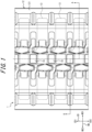
- FIG. 3 is a perspective view illustrating a plurality of adjacent cores 13 when the rubber crawler 1 in FIG. 1 is in a flat state.
- "when the rubber crawler 1 is in a flat state” refers to a state in which, when only a part of the rubber crawler 1 in the crawler circumferential direction CD is viewed, the part is not bent by being wound around a sprocket or the like, but is flat.
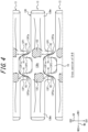
- FIG. 4 is a cross-sectional view taken along the line B-B of FIG. 3 , illustrating a cross section of B-B of the plurality of cores 13 of FIG. 3 .
- FIG. 4 corresponds to a state in which each of the cores 13 in FIG. 3 is cut near the root of a horn portion 13C of the core and viewed from the crawler inner circumferential side IS.
- a plurality of cores 13 provided in the rubber crawler 1 are arranged along the crawler circumferential direction CD.
- the core 13 is made of metal (such as iron or steel).
- At least a part of the core 13 is buried inside the crawler body 12.
- the core 13 is arranged on the crawler inner circumferential side IS with respect to the core body layer 15 ( FIG. 2 ).
- FIG. 5 and FIG. 7 illustrate the core 13 of the present embodiment as a single unit from different angles, respectively.
- each core 13 is the same. In the following description, when a core 13 is described, the same applies to each of the cores 13.
- the core 13 includes a base portion 13B, a pair of horn portions 13C, a pair of first projections (projection) 13P1, and a pair of second projections (projection) 13P2.
- the base portion 13B extends in the crawler width direction WD.
- the base portion 13B is configured in a substantially plate shape in the present embodiment.
- the base portion 13B as illustrated in FIG. 4 , has a substantially rectangular shape with the crawler width direction WD as the longitudinal direction when viewed from the crawler inner circumferential side IS.
- the base portion 13B may have other shapes different from the one in the present embodiment.
- the pair of horn portions 13C each extend from the base portion 13B to the crawler inner circumferential side IS. A part or the whole of the horn portion 13C protrudes toward the crawler inner circumferential side IS from the inner circumferential surface 121 of the crawler body 12 ( FIG. 2 ).
- the pair of horn portions 13C are spaced from each other in the crawler width direction WD.
- the pair of horn portions 13C are positioned on the two sides of the center in the crawler width direction WD of the base portion 13B, respectively.
- the pair of horn portions 13C of the core 13 have a function as a guide which restricts the movement of each rotator at the foot of the traveling machine (sprocket, idler, and track roller) in the crawler width direction WD without rubber or via rubber, thereby preventing loss of a wheel.
- the top surfaces 13Ca of the pair of horn portions 13C are configured so that a track roller passes over them.
- a track roller may be configured not to run on the top surfaces 13Ca of the pair of horn portions 13C, but to run on the outer side in the crawler width direction WD of the pair of horn portions 13C, for example.
- a portion of the base portion 13B where the pair of horn portions 13C are connected is a central portion 13Bc.
- a portion of the base portion 13B outside the pair of horn portions 13C in the crawler width direction WD is a pair of wing portions 13Bw.
- the central portion 13Bc of the base portion 13B of the core 13 has a function of transmitting the driving force from a sprocket to the rubber crawler 1 by engagement with a pin of the sprocket without rubber or via rubber.
- the base portion 13B of the core 13 may be entirely covered by the crawler body 12, or a part thereof (such as the central portion 13Bc) may be exposed to the outside without being covered by the crawler body 12.
- a part or the whole of a portion protruding from the inner circumferential surface 121 of the crawler body 12 toward the crawler inner circumferential side IS may be covered with a film-like coating rubber or may be exposed to the outside without being covered with a film-like coating rubber.
- a hole 16 is formed between the central portions 13Bc of adjacent cores 13 in the crawler circumferential direction CD.
- the hole 16 is recessed toward the crawler outer circumferential side.
- the hole 16 is configured to allow entry of a pin of a sprocket. In this way, a pin of a sprocket can engage with the central portion 13Bc of the core 13 while being inserted into the hole 16, thus allowing the driving force to be transmitted to the rubber crawler 1.
- the hole 16 may be configured as a bottomless hole (through hole) that penetrates the crawler body 12 in the crawler thickness direction TD, or it may be configured as a bottomed hole (recess) that does not penetrate the crawler body 12 in the crawler thickness direction TD.
- the pair of first projections 13P1 each extend from the base portion 13B to the crawler circumferential direction first side CD1.
- the pair of first projections 13P1 are spaced from each other in the crawler width direction WD.
- the pair of first projections 13P1 are positioned on the two sides of the center in the crawler width direction WD of the base portion 13B, respectively.
- the pair of first projections 13P1 are positioned near the pair of horn portions 13C in the crawler width direction WD.
- a hole 16 is formed between the pair of first projections 13P1.
- the pair of second projections 13P2 each extend from the base portion 13B to the crawler circumferential direction second side CD2.
- the pair of second projections 13P2 are spaced from each other in the crawler width direction WD.
- the pair of second projections 13P2 are positioned on the two sides of the center in the crawler width direction WD of the base portion 13B, respectively.
- the pair of second projections 13P2 are positioned near the pair of horn portions 13C in the crawler width direction WD.
- a hole 16 is formed between the pair of second projections 13P2.
- the pair of first projections 13P1 of each core 13 respectively face, in the crawler width direction WD, the pair of second projection 13P2 of another core 13 adjacent to the core 13 on the crawler circumferential direction first side CD1.
- the pair of first projections 13P1 of each core 13 and the pair of second projections 13P2 of another core 13 adjacent to the core 13 on the crawler circumferential direction first side CD1 restrict the movement of each other in the crawler width direction WD by engagement (interference) with each other.
- slip (side slip) between the cores 13 in the crawler width direction WD can be prevented, thereby improving the rigidity of the rubber crawler 1 and preventing loss of a wheel and the like.
- the pair of first projections 13P1 of a core 13 are positioned on the outer side in the crawler width direction WD with respect to the pair of second projections 13P2 of another core 13 adjacent to the core 13 on the crawler circumferential direction first side CD1.
- pair of first projections 13P1 of a core 13 may be in any positional relationship in the crawler width direction WD with respect to the pair of second projections 13P2 of another core 13 adjacent to the core 13 on the crawler circumferential direction first side CD1.
- a clearance (gap) g exists between the pair of first projections 13P1 of a core 13 and the pair of second projections 13P2 of another core 13 adjacent to the core 13 on the crawler circumferential direction first side CD1.
- the first projection 13P1 and the second projection 13P2 basically have similar configurations. In the following description, they will be described together for convenience.
- the pair of first projections 13P1 of a core 13 respectively have a first recess R1 on a surface 13P1a facing the second projections 13P2 of another adjacent core 13 (the surface on the inner side in the crawler width direction WD in the present embodiment) of the surfaces on the two sides in the crawler width direction WD.
- the pair of second projections 13P2 of each core 13 respectively have a second recess R2 on a surface 13P2a facing the first projections 13P1 of another adjacent core 13 (the surface on the outer side in the crawler width direction WD in the present embodiment) of the surfaces on the two sides in the crawler width direction WD.
- FIG. 9 is a perspective view illustrating a plurality of adjacent cores 13 when the rubber crawler 1 of the present embodiment is bent around a sprocket or the like.
- "when the rubber crawler 1 is bent around a sprocket or the like” refers to a state in which, when only a part in the crawler circumferential direction CD of the rubber crawler 1 is viewed, the part is bent by being wound around a sprocket or an idler.
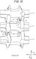
- FIG. 10 is a G-arrow view illustrating the plurality of cores 13 in FIG. 9 when viewed in the direction of the G arrow.
- the core 13 Since the core 13 is on the crawler inner circumferential side IS with respect to the core layer 15, adjacent cores 13 come closer to each other when the rubber crawler 1 is bent around a sprocket or an idler, as illustrated in FIG. 9 . As a result, the clearance g between the first projection 13P1 and the second projection 13P2 of the adjacent cores 13 is narrowed.
- the first projection 13P1 and the second projection 13P2 have a first recess R1 and a second recess R2, respectively, on surfaces 13P1a and 13P2a facing each other, and the first recess R1 and the second recess R2 face each other.
- the clearance g can be expanded when the rubber crawler 1 is bent around a sprocket or the like, and the risk of contact (interference) between the first projection 13P1 and the second projection 13P2 can be reduced when the rubber crawler 1 is bent around a sprocket or the like, as illustrated in FIG 10 . Therefore, when the rubber crawler 1 is bent around a sprocket or the like, the flexural rigidity of the rubber crawler 1 can be prevented from becoming too high. As a result, the possibility that the rubber crawler 1 is difficult to be wound around a sprocket or the like and the possibility of an increase in loss of driving force can be reduced.
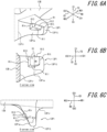
- FIG. 6A is an enlarged view of the first projection 13P1 in FIG. 5
- FIG. 6B is a C-arrow view illustrating the first projection 13P1 in FIG. 5 when viewed in the direction of the C arrow
- FIG. 6C is a D-arrow view illustrating the first projection 13P1 in FIG. 5 when viewed in the direction of the D arrow.
- the first projection 13P1 has a first section surface R11 facing the crawler inner circumferential side IS, a second section surface R12 facing the side facing the second projection 13P2 of another core 13 (the inner side in the crawler width direction WD in the present embodiment) of the two sides in the crawler width direction WD, and a third section surface R13 facing the crawler circumferential direction first side CD1, on the surface 13P1a facing the second projection 13P2 of another adjacent core 13 (the surface on the inner side in the crawler width direction WD in the present embodiment) of the surfaces on the two sides in the crawler width direction WD.
- the first recess R1 is defined by the first section surface R11, the second section surface R12, the third section surface R13, an opening in the surface 13P1a facing the second projection 13P2 of another core 13 (the surface on the inner side in the crawler width direction WD in the present embodiment) of the surfaces on the two sides in the crawler width direction WD of the first projection 13P1 in the first recess R1, and an opening in the surface on the crawler inner circumferential side IS of the first projection 13P1 in the first recess R1.
- FIG. 8A is an enlarged view of the second projection 13P2 in FIG. 7
- FIG. 8B is an E-arrow view illustrating the second projection 13P2 in FIG. 7 when viewed in the direction of the E arrow
- FIG. 8C is an F-arrow view illustrating the second projection 13P2 in FIG. 7 when viewed in the direction of the F arrow.
- the second projection 13P2 has a first section surface R21 facing the crawler inner circumferential side IS, a second section surface R22 facing the side facing the first projection 13P1 of another core 13 (the outer side in the crawler width direction WD in the present embodiment) of the two sides in the crawler width direction WD, and a third section surface R23 facing the crawler circumferential direction second side CD2, on the surface 13P2a facing the first projection 13P1 of another adjacent core 13 (the surface on the outer side in the crawler width direction WD in the present embodiment) of the surfaces on the two sides in the crawler width direction WD.
- the second recess R2 is defined by the first section surface R21, the second section surface R22, the third section surface R23, an opening in the surface 13P2a facing the first projection 13P1 of another core 13 (the surface on the outer side in the crawler width direction WD in the present embodiment) of the surfaces on the two sides in the crawler width direction WD of the second projection 13P2 in the second recess R2, and an opening in the surface on the crawler inner circumferential side IS of the second projection 13P2 in the second recess R2.
- an end R1t on the side of a tip 13P1t of the first projection 13P1 in the crawler circumferential direction CD of the first recess R1 is preferably positioned closer to the side of a root 13P1r of the first projection 13P1 than the tip 13P11 of the first projection 13P1 in the crawler circumferential direction CD.
- the first recess R1 is arranged in a portion where the first projection 13P1 and the second projection 13P2 are highly likely to come into contact with each other when the rubber crawler 1 is bent around a sprocket or the like, so that the contact between the first projection 13P1 and the second projection 13P2 can be suppressed, and a decrease in ease of engagement between the first projection 13P1 and the second projection 13P2 when the cores 13 adjacent to each other move relative to each other in the crawler width direction WD and a decrease in rigidity of the first projection 13P1 can be suppressed.
- the "tip 13P1t of the first projection 13P1” refers to the end on the crawler circumferential direction first side CD1 of the first projection 13P1. Therefore, the “end R1t on the side of a tip 13P1t of the first projection 13P1 in the crawler circumferential direction CD" of the first recess R1 refers to the end on the crawler circumferential direction first side CD1 of the first recess R1. Further, the “root 13P1r of the first projection 13P1” refers to the end on the crawler circumferential direction second side CD2 of the first projection 13P1. The root 13P1r of the first projection 13P1 is connected to the end surface on the crawler circumferential direction first side CD1 of the base portion 13B.
- an end R2t on the side of a tip 13P2t of the second projection 13P2 in the crawler circumferential direction CD of the second recess R2 is preferably positioned closer to the side of a root 13P2r of the second projection 13P2 than the tip 13P2t of the second projection 13P2 in the crawler circumferential direction CD.
- the second recess R2 is arranged in a portion where the first projection 13P1 and the second projection 13P2 are highly likely to come into contact with each other when the rubber crawler 1 is bent around a sprocket or the like, so that the contact between the first projection 13P1 and the second projection 13P2 can be suppressed, and a decrease in ease of engagement between the first projection 13P1 and the second projection 13P2 when the cores 13 adjacent to each other move relative to each other in the crawler width direction WD and a decrease in rigidity of the second projection 13P2 can be suppressed.
- the "tip 13P2t of the second projection 13P2” refers to the end on the crawler circumferential direction second side CD2 of the second projection 13P2. Therefore, the “end R2t on the side of a tip 13P2t of the second projection 13P2 in the crawler circumferential direction CD" of the second recess R2 refers to the end on the crawler circumferential direction second side CD2 of the second recess R2. Further, the “root 13P2r of the second projection 13P2” refers to the end on the crawler circumferential direction first side CD1 of the second projection 13P2. The root 13P2r of the second projection 13P2 is connected to the end surface on the crawler circumferential direction second side CD2 of the base portion 13B.
- the rigidity of the first projection 13P1 may be excessively deteriorated, and when the rubber crawler 1 is bent around a sprocket or the like, the first projection 13P1 and the second projection 13P2 may undesirably engage with each other if, for example, a twist occurs between the cores 13 adjacent to each other.
- the rigidity of the second projection 13P2 may be excessively deteriorated, and when the rubber crawler 1 is bent around a sprocket or the like, the first projection 13P1 and the second projection 13P2 may undesirably engage with each other if, for example, a twist occurs between the cores 13 adjacent to each other.
- the length L1 in the crawler width direction WD preferably increases as it goes toward the side of the root 13P1r of the first projection 13P1 in the crawler circumferential direction CD, as illustrated in FIG. 6C .
- the first recess R1 is arranged in a portion where the first projection 13P1 and the second projection 13P2 are highly likely to come into contact with each other when the rubber crawler 1 is bent around a sprocket or the like, so that the contact between the first projection 13P1 and the second projection 13P2 can be suppressed, and a decrease in ease of engagement between the first projection 13P1 and the second projection 13P2 when the cores 13 adjacent to each other move relative to each other in the crawler width direction WD and a decrease in rigidity of the first projection 13P1 can be suppressed.
- the length L2 in the crawler width direction WD preferably increases as it goes toward the side of the root 13P2r of the second projection 13P2 in the crawler circumferential direction CD, as illustrated in FIG. 8C .
- the second recess R2 is arranged in a portion where the first projection 13P1 and the second projection 13P2 are highly likely to come into contact with each other when the rubber crawler 1 is bent around a sprocket or the like, so that the contact between the first projection 13P1 and the second projection 13P2 can be suppressed, and a decrease in ease of engagement between the first projection 13P1 and the second projection 13P2 when the cores 13 adjacent to each other move relative to each other in the crawler width direction WD and a decrease in rigidity of the second projection 13P2 can be suppressed.
- the first recess R1 is preferably open on the crawler inner circumferential side IS (that is, open on the surface on the crawler inner circumferential side IS of the first projection 13P1) and closed on the crawler outer circumferential side OS (that is, not open on the surface on the crawler outer circumferential side OS of the first projection 13P1), as illustrated in FIGS. 6A and 6B .
- the clearance g between the first projection 13P1 and the second projection 13P2 tends to narrow especially on the crawler inner circumferential side IS, and conversely, the clearance g tends to widen on the crawler outer circumferential side OS.
- the first recess R1 is arranged in a portion where the first projection 13P1 and the second projection 13P2 are highly likely to come into contact with each other when the rubber crawler 1 is bent around a sprocket or the like, so that the contact between the first projection 13P1 and the second projection 13P2 can be suppressed, and a decrease in ease of engagement between the first projection 13P1 and the second projection 13P2 when the cores 13 adjacent to each other move relative to each other in the crawler width direction WD and a decrease in rigidity of the first projection 13P1 can be suppressed.
- the second recess R2 is preferably open on the crawler inner circumferential side IS (that is, open on the surface on the crawler inner circumferential side IS of the second projection 13P2) and closed on the crawler outer circumferential side OS (that is, not open on the surface on the crawler outer circumferential side OS of the second projection 13P2), as illustrated in FIGS. 8A and 8B .
- the clearance g between the first projection 13P1 and the second projection 13P2 tends to narrow especially on the crawler inner circumferential side IS, and conversely, the clearance g tends to widen on the crawler outer circumferential side OS.
- the second recess R2 is arranged in a portion where the first projection 13P1 and the second projection 13P2 are highly likely to come into contact with each other when the rubber crawler 1 is bent around a sprocket or the like, so that the contact between the first projection 13P1 and the second projection 13P2 can be suppressed, and a decrease in ease of engagement between the first projection 13P1 and the second projection 13P2 when the cores 13 adjacent to each other move relative to each other in the crawler width direction WD and a decrease in rigidity of the second projection 13P2 can be suppressed.
- first recess R1 and the second recess R2 are not open on the crawler inner circumferential side IS, the first projection 13P1 and the second projection 13P2 tends to come into contact with each other when the rubber crawler 1 is bent around a sprocket or the like.
- the first recess R1 preferably has a substantially triangular prism shape, as illustrated in FIG. 6A .
- the substantially triangular prism shape has the first section surface R11 as the bottom surface and has the crawler thickness direction TD as the height direction.
- the first section surface R11 has a substantially triangular shape.
- the first recess R1 When the first recess R1 has such a shape, the first recess R1 is arranged in a portion where the first projection 13P1 and the second projection 13P2 are highly likely to come into contact with each other when the rubber crawler 1 is bent around a sprocket or the like, so that the contact between the first projection 13P1 and the second projection 13P2 can be suppressed, and a decrease in ease of engagement between the first projection 13P1 and the second projection 13P2 when the cores 13 adjacent to each other move relative to each other in the crawler width direction WD and a decrease in rigidity of the first projection 13P1 can be suppressed.
- the second recess R2 preferably has a substantially triangular prism shape, as illustrated in FIG. 8A .
- the substantially triangular prism shape has the first section surface R21 as the bottom surface and has the crawler thickness direction TD as the height direction.
- the first section surface R21 has a substantially triangular shape.
- the second recess R2 When the second recess R2 has such a shape, the second recess R2 is arranged in a portion where the first projection 13P1 and the second projection 13P2 are highly likely to come into contact with each other when the rubber crawler 1 is bent around a sprocket or the like, so that the contact between the first projection 13P1 and the second projection 13P2 can be suppressed, and a decrease in ease of engagement between the first projection 13P1 and the second projection 13P2 when the cores 13 adjacent to each other move relative to each other in the crawler width direction WD and a decrease in rigidity of the second projection 13P2 can be suppressed.
- the term "substantially triangular prism shape” is a concept including a substantially truncated triangular prism shape.
- the first recess R1 and the second recess R2 have the first section surfaces R11 and R21, which are bottom surfaces, inclined with respect to the height direction (crawler thickness direction TD), thereby forming a substantially truncated triangular prism shape.
- the length M1 in the crawler thickness direction TD of the first recess R1 preferably increases as it goes toward the side of the root 13P1r of the first projection 13P1 in the crawler circumferential direction CD, as illustrated in FIG. 6B .
- the first recess R1 is arranged in a portion where the first projection 13P1 and the second projection 13P2 are highly likely to come into contact with each other when the rubber crawler 1 is bent around a sprocket or the like, so that the contact between the first projection 13P1 and the second projection 13P2 can be suppressed, and a decrease in ease of engagement between the first projection 13P1 and the second projection 13P2 when the cores 13 adjacent to each other move relative to each other in the crawler width direction WD and a decrease in rigidity of the first projection 13P1 can be suppressed.
- the length M1 in the crawler thickness direction TD of the first recess R1 refers to the maximum value thereof.
- the length M1 in the crawler thickness direction TD" of the first recess R1 is the length in the crawler thickness direction TD of the first recess R1, which is measured at the end of the side facing the second projection 13P2 of another core 13 (the inner side in the crawler width direction WD in the present embodiment) of the two sides in the crawler width direction WD.
- the first section surface R11 of the first recess R1 preferably extends toward the crawler outer circumferential side OS as it goes toward the side of the root 13P1r of the first projection 13P1 in the crawler circumferential direction CD.
- the length M2 in the crawler thickness direction TD of the second recess R2 preferably increases as it goes toward the side of the root 13P2r of the second projection 13P2 in the crawler circumferential direction CD, as illustrated in FIG. 8B .
- the second recess R2 is arranged in a portion where the first projection 13P1 and the second projection 13P2 are highly likely to come into contact with each other when the rubber crawler 1 is bent around a sprocket or the like, so that the contact between the first projection 13P1 and the second projection 13P2 can be suppressed, and a decrease in ease of engagement between the first projection 13P1 and the second projection 13P2 when the cores 13 adjacent to each other move relative to each other in the crawler width direction WD and a decrease in rigidity of the second projection 13P2 can be suppressed.
- the length M2 in the crawler thickness direction TD of the second recess R2 refers to the maximum value thereof.
- the length M2 in the crawler thickness direction TD" of the second recess R2 is the length in the crawler thickness direction TD of the second recess R2, which is measured at the end of the side facing the first projection 13P1 of another core 13 (the outer side in the crawler width direction WD in the present embodiment) of the two sides in the crawler width direction WD.
- the first section surface R21 of the second recess R2 preferably extends toward the crawler outer circumferential side OS as it goes toward the side of the root 13P2r of the second projection 13P2 in the crawler circumferential direction CD.
- a ratio of the length M1 in the crawler thickness direction TD of the first recess R1 to the length in the crawler thickness direction TD of the first projection 13P1, which is measured at a position in the crawler width direction WD and the crawler circumferential direction CD where the length M1 in the crawler thickness direction TD of the first recess R1 ( FIG. 6B ) is maximum, is preferably 30 % to 70 %.
- the first recess R1 is arranged in a portion where the first projection 13P1 and the second projection 13P2 are highly likely to come into contact with each other when the rubber crawler 1 is bent around a sprocket or the like, so that the contact between the first projection 13P1 and the second projection 13P2 can be suppressed, and a decrease in ease of engagement between the first projection 13P1 and the second projection 13P2 when the cores 13 adjacent to each other move relative to each other in the crawler width direction WD and a decrease in rigidity of the first projection 13P1 can be suppressed.
- the "position in the crawler width direction WD and the crawler circumferential direction CD where the length M1 in the crawler thickness direction TD of the first recess R1 is maximum" specifically refers to a position in the crawler width direction WD and the crawler circumferential direction CD on the side facing the second projection 13P2 of another core 13 (the inner side in the crawler width direction WD in the present embodiment) of the two sides in the crawler width direction WD and at the end on the crawler circumferential direction second side CD2 of the first recess R1.
- a ratio of the length M2 in the crawler thickness direction TD of the second recess R2 to the length in the crawler thickness direction TD of the second projection 13P2, which is measured at a position in the crawler width direction WD and the crawler circumferential direction CD where the length M2 in the crawler thickness direction TD of the second recess R2 ( FIG. 8B ) is maximum, is preferably 30 % to 70 %.
- the second recess R2 is arranged in a portion where the first projection 13P1 and the second projection 13P2 are highly likely to come into contact with each other when the rubber crawler 1 is bent around a sprocket or the like, so that the contact between the first projection 13P1 and the second projection 13P2 can be suppressed, and a decrease in ease of engagement between the first projection 13P1 and the second projection 13P2 when the cores 13 adjacent to each other move relative to each other in the crawler width direction WD and a decrease in rigidity of the second projection 13P2 can be suppressed.
- the "position in the crawler width direction WD and the crawler circumferential direction CD where the length M2 in the crawler thickness direction TD of the second recess R2 is maximum" specifically refers to a position in the crawler width direction WD and the crawler circumferential direction CD on the side facing the first projection 13P1 of another core 13 (the outer side in the crawler width direction WD in the present embodiment) of the two sides in the crawler width direction WD and at the end on the crawler circumferential direction first side CD1 of the second recess R2.
- the surface 13P1a facing the second projection 13P2 of another adjacent core 13 (the surface on the inner side in the crawler width direction WD in the present embodiment) of the surfaces on the two sides in the crawler width direction WD preferably extends toward the side facing the second projection 13P2 of another core 13 (the inner side in the crawler width direction WD in the present embodiment) of the two sides in the crawler width direction WD as it goes toward the side of the root 13P1r of the first projection 13P1 in the crawler circumferential direction CD, as illustrated in FIGS. 6A to 6C .
- the surface on the crawler inner circumferential side IS is preferably substantially perpendicular to the crawler thickness direction TD.
- the first section surface R11 of the first recess R1 preferably extends toward the crawler outer circumferential side OS as it goes toward the side facing the second projection 13P2 of another core 13 (the inner side in the crawler width direction WD in the present embodiment) of the two sides in the crawler width direction WD.
- the second section surface R12 of the first recess R1 preferably extends toward the side facing the second projection 13P2 of another core 13 (the inner side in the crawler width direction WD in the present embodiment) of the two sides in the crawler width direction WD as it goes toward the side of the root 13P1r of the first projection 13P1 in the crawler circumferential direction CD.
- the third section surface R13 of the first recess R1 preferably extends toward the side facing the second projection 13P2 of another core 13 (the inner side in the crawler width direction WD in the present embodiment) of the two sides in the crawler width direction WD as it goes toward the side of the root 13P1r of the first projection 13P1 in the crawler circumferential direction CD.
- the angle of the acute-angle side with respect to the crawler width direction WD of the third section surface R13 is preferably smaller than the angle of the acute-angle side with respect to the crawler width direction WD of the second section surface R12.
- the surface 13P2a facing the first projection 13P1 of another adjacent core 13 (the surface on the outer side in the crawler width direction WD in the present embodiment) of the surfaces on the two sides in the crawler width direction WD preferably extends toward the side facing the first projection 13P1 of another core 13 (the outer side in the crawler width direction WD in the present embodiment) of the two sides in the crawler width direction WD as it goes toward the side of the root 13P2r of the second projection 13P2 in the crawler circumferential direction CD, as illustrated in FIGS. 8A to 8C .
- the surface on the crawler inner circumferential side IS is preferably substantially perpendicular to the crawler thickness direction TD.
- the first section surface R21 of the second recess R2 preferably extends toward the crawler outer circumferential side OS as it goes toward the side facing the first projection 13P1 of another core 13 (the outer side in the crawler width direction WD in the present embodiment) of the two sides in the crawler width direction WD.
- the second section surface R22 of the second recess R2 preferably extends toward the side facing the first projection 13P1 of another core 13 (the outer side in the crawler width direction WD in the present embodiment) of the two sides in the crawler width direction WD as it goes toward the side of the root 13P2r of the second projection 13P2 in the crawler circumferential direction CD.
- the third section surface R23 of the second recess R2 preferably extends toward the side facing the first projection 13P1 of another core 13 (the outer side in the crawler width direction WD in the present embodiment) of the two sides in the crawler width direction WD as it goes toward the side of the root 13P2r of the second projection 13P2 in the crawler circumferential direction CD.
- the angle of the acute-angle side with respect to the crawler width direction WD of the third section surface R23 is preferably smaller than the angle of the acute-angle side with respect to the crawler width direction WD of the second section surface R22.
- each of the pair of first projections 13P1 of the core 13 has a first recess R1
- each of the pair of second projections 13P2 of the core 13 has a second recess R2 ( FIG. 4 ).
- the clearance P between the first projection 13P1 and the second projection 13P2 is widened when the rubber crawler 1 is bent around a sprocket or the like.
- the effect of suppressing the contact between the first projection 13P1 and the second projection 13P2 when the rubber crawler 1 is bent around a sprocket or the like is the best.
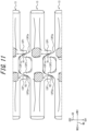
- first projection 13P1 on the crawler width direction first side WD1 of the pair of first projections 13P1 of the core 13 has a first recess R1
- second projection 13P2 on the crawler width direction second side WD2 of the pair of second projections 13P2 of the core 13 has a second recess R2, as in the modified example illustrated in FIG. 11 .
- the surface 13P1a facing the second projection 13P2 of another adjacent core 13 of the surfaces on the two sides in the crawler width direction WD is a substantially flat surface
- the surface 13P2a facing the first projection 13P1 of another adjacent core 13 of the surfaces on the two sides in the crawler width direction WD is a substantially flat surface
- the clearance P between the first projection 13P1 and the second projection 13P2 when the rubber crawler 1 is bent around a sprocket or the like is widened compared to a case where neither a first recess R1 nor a second recess R2 is provided (that is, a case where substantially flat surfaces face each other).
- a case where substantially flat surfaces face each other that is, a case where substantially flat surfaces face each other.
- first projection 13P1 on the crawler width direction first side WD1 of the pair of first projections 13P1 of the core 13 has a first recess R1
- neither of the pair of second projections 13P2 of the core 13 has a second recesses R2.
- the first recess R1 faces a substantially flat surface on the crawler width direction first side WD1
- the clearance P between the first projection 13P1 and the second projection 13P2 when the rubber crawler 1 is bent around a sprocket or the like is widened compared to a case where neither a first recess R1 nor a second recess R2 is provided.
- the contact between the first projection 13P1 and the second projection 13P2 can be suppressed.
- the rubber crawler of the present disclosure can be suitably mounted on a foot portion of any traveling machine such as a construction machine (for example, a compact excavator) or an agricultural machine (for example, a tractor or a combine).
- a construction machine for example, a compact excavator
- an agricultural machine for example, a tractor or a combine.
Landscapes
- Engineering & Computer Science (AREA)
- Chemical & Material Sciences (AREA)
- Combustion & Propulsion (AREA)
- Transportation (AREA)
- Mechanical Engineering (AREA)
- Gears, Cams (AREA)
- Harvester Elements (AREA)
Abstract
Description
- This disclosure relates to a rubber crawler and a core.
- In a conventional rubber crawler, a core may include a projection extending in the crawler circumferential direction that protrudes from a base portion extending in the crawler width direction, to prevent side slip or the like (for example, see
JP 2005-212741 A - PTL 1:
JP 2005-212741 A - When a conventional rubber crawler is bent around a sprocket or the like, the cores are close to each other, and the clearance (gap) between the projections of adjacent cores is too narrow. As a result, the flexural rigidity of the rubber crawler is too high, which may make it difficult to wind the rubber crawler around a rotator and increase the loss of driving force.
- It could thus be helpful to provide a rubber crawler and a core which can enlarge the clearance between projections of adjacent cores when a rubber crawler is bent around a sprocket or the like.
- [1] A rubber crawler comprising:
- an endless crawler body made of rubber, and
- a plurality of cores embedded in the crawler body and arranged along a crawler circumferential direction, wherein
- each of the cores comprises:
- a base portion extending in a crawler width direction,
- a pair of horn portions extending from the base portion to a crawler inner circumferential side,
- a pair of first projections extending from the base portion to a crawler circumferential direction first side, and
- a pair of second projections extending from the base portion to a crawler circumferential direction second side, wherein
- the pair of first projections of each of the cores respectively face the pair of second projections of another core adjacent to the core on the crawler circumferential direction first side in a crawler width direction,
- at least a first projection on a crawler width direction first side in the pair of first projections of each of the cores has a first recess on a surface facing the second projection of another core of surfaces on two sides in a crawler width direction,
- in the first recess, an end on a side of a tip of the first projection in a crawler circumferential direction of the first recess is positioned closer to a side of a root of the first projection than a tip of the first projection in a crawler circumferential direction,
- for the first recess, in a portion including at least an end on a side of a tip of the first projection in a crawler circumferential direction, a length in a crawler width direction increases as it goes toward a side of a root of the first projection in a crawler circumferential direction,
- the first recess is open on a crawler inner circumferential side and closed on a crawler outer circumferential side, and
- the first recess has a substantially triangular prism shape.
- [4] The core used in the rubber crawler described above.
- According to the present disclosure, it is possible to provide a rubber crawler and a core which can enlarge the clearance between projections of adjacent cores when a rubber crawler is bent around a sprocket or the like.
- In the accompanying drawings:
-
FIG. 1 schematically illustrates a rubber crawler according to an embodiment of the present disclosure as viewed from the crawler inner circumferential side; -
FIG. 2 is a cross-sectional view taken along the line A-A ofFIG. 1 , illustrating a cross section of A-A of the rubber crawler ofFIG. 1 ; -
FIG. 3 is a perspective view illustrating a plurality of adjacent cores when the rubber crawler inFIG. 1 is in a flat state; -
FIG. 4 is a cross-sectional view taken along the line B-B ofFIG. 3 , illustrating a cross section of B-B of the plurality of cores ofFIG. 3 ; -
FIG. 5 is a perspective view illustrating a core inFIG. 3 when viewed from the side of a first projection; -
FIG. 6A is an enlarged view of the first projection inFIG. 5 ,FIG. 6B is a C-arrow view illustrating the first projection inFIG. 5 when viewed in the direction of the C arrow, andFIG. 6C is a D-arrow view illustrating the first projection inFIG. 5 when viewed in the direction of the D arrow; -
FIG. 7 is a perspective view illustrating a core inFIG. 3 when viewed from the side of a second projection; -
FIG. 8A is an enlarged view of the second projection inFIG. 7 ,FIG. 8B is an E-arrow view illustrating the second projection inFIG. 7 when viewed in the direction of the E arrow, andFIG. 8C is an F-arrow view illustrating the second projection inFIG. 7 when viewed in the direction of the F arrow; -
FIG. 9 is a perspective view illustrating a plurality of adjacent cores when the rubber crawler inFIG. 1 is bent around a sprocket or the like; -
FIG. 10 is a G-arrow view illustrating the plurality of cores inFIG. 9 when viewed in the direction of the G arrow; and -
FIG. 11 is a drawing corresponding toFIG. 4 , which is a drawing for explaining a rubber crawler according to a modified example of the present disclosure. - The rubber crawler of the present disclosure can be suitably mounted on a foot portion of any traveling machine such as a construction machine (for example, a compact excavator) or an agricultural machine (for example, a tractor or a combine).
- The following describes embodiments of the rubber crawler and the core of the present disclosure with reference to the drawings.
- The same components in the drawings are denoted by the same reference numerals.
-
FIG. 1 schematically illustrates arubber crawler 1 according to an embodiment of the present disclosure as viewed from the crawler inner circumferential side.FIG. 2 is a cross-sectional view taken along the line A-A ofFIG. 1 , illustrating a cross section of A-A of therubber crawler 1 ofFIG. 1 . The line A-A inFIG. 1 extends along the crawler width direction. - It is preferable to mount the
rubber crawler 1 on a foot portion of a traveling machine such as a construction machine (for example, a compact excavator) or an agricultural machine (for example, a tractor or a combine). Although not illustrated in the drawings, the foot portion of a traveling machine includes a sprocket that is a drive wheel, one or more idlers that are idling wheels, and one or more track rollers. The sprocket has a plurality of pins on its outer circumferential side. - As illustrated in
FIGS. 1 and2 , therubber crawler 1 according to the present embodiment includes acrawler body 12, a plurality oflugs 14, one or morecore body layers 15, and a plurality ofcores 13 according to an embodiment of the present disclosure. In this way, thecore 13 according to the present embodiment is used in therubber crawler 1 according to the present embodiment. - The
crawler body 12 is formed in an endless shape (annular shape). Thecrawler body 12 is configured in a band shape. Thecrawler body 12 is made of rubber. - In the present specification, the "crawler inner circumferential side IS", "crawler outer circumferential side OS", "crawler circumferential direction CD", "crawler width direction WD", and "crawler thickness direction TD" refer to the inner circumferential side, the outer circumferential side, the circumferential direction, the width direction, and the thickness direction of the
crawler body 12, respectively, as indicated by arrows in the drawings. - In the present specification, one side in the crawler circumferential direction CD is referred to as "crawler circumferential direction first side CD1", and the other side in the crawler circumferential direction CD is referred to as "crawler circumferential direction second side CD2", as indicated by arrows in the drawings. In the present specification, one side in the crawler width direction WD is referred to as "crawler width direction first side WD1", and the other side in the crawler width direction WD is referred to as "crawler width direction second side WD2", as indicated by arrows in the drawings.
- In the present specification, the "outer side in the crawler width direction WD" refers to a side farther from the center of the crawler width direction WD of the
crawler body 12 in the crawler width direction WD, and the "inner side in the crawler width direction WD" refers to a side closer to the center of the crawler width direction WD of thecrawler body 12 in the crawler width direction WD. - The rotation direction of the
rubber crawler 1 during running of the traveling machine may be to the crawler circumferential direction first side CD1 or to the crawler circumferential direction second side CD2. - The plurality of
lugs 14 provided in therubber crawler 1 each protrude from the outercircumferential surface 122 of thecrawler body 12 to the crawler outer circumferential side OS. The shape and arrangement of thelugs 14 may be arbitrary. An end surface of thelug 14 on the crawler outer circumferential side OS is configured to be in contact with a road surface. Thelugs 14 are made of rubber. - In the present embodiment, the
core body layer 15 has a plurality ofcords 15C arranged along the crawler width direction WD. Each of thesecords 15C extends along the entire circumference along the crawler circumferential direction CD. Thecore body layer 15 is buried inside thecrawler body 12. Therubber crawler 1 may include thecore body layer 15 only at one position in the crawler thickness direction TD, as in the example ofFIG. 2 (in this case, the number of layers of thecore body layer 15 is one). Alternatively, therubber crawler 1 may include the core body layers 15 at a plurality of positions in the crawler thickness direction TD (in this case, the number of layers of thecore body layer 15 is more than one). - The
core body layer 15 has a function of preventing thecrawler body 12 from extending in the crawler circumferential direction CD. - The
cord 15C is made of metal (such as steel), for example. -
FIG. 3 is a perspective view illustrating a plurality ofadjacent cores 13 when therubber crawler 1 inFIG. 1 is in a flat state. As used herein, "when therubber crawler 1 is in a flat state" refers to a state in which, when only a part of therubber crawler 1 in the crawler circumferential direction CD is viewed, the part is not bent by being wound around a sprocket or the like, but is flat.FIG. 4 is a cross-sectional view taken along the line B-B ofFIG. 3 , illustrating a cross section of B-B of the plurality ofcores 13 ofFIG. 3 .FIG. 4 corresponds to a state in which each of thecores 13 inFIG. 3 is cut near the root of ahorn portion 13C of the core and viewed from the crawler inner circumferential side IS. - As illustrated in
FIGS. 1 ,3 , and4 , a plurality ofcores 13 provided in therubber crawler 1 are arranged along the crawler circumferential direction CD. - The
core 13 is made of metal (such as iron or steel). - At least a part of the
core 13 is buried inside thecrawler body 12. Thecore 13 is arranged on the crawler inner circumferential side IS with respect to the core body layer 15 (FIG. 2 ). -
FIG. 5 andFIG. 7 illustrate thecore 13 of the present embodiment as a single unit from different angles, respectively. - The configuration of each core 13 is the same. In the following description, when a
core 13 is described, the same applies to each of thecores 13. - As illustrated in
FIGS. 3 ,4 ,5 , and7 , thecore 13 includes abase portion 13B, a pair ofhorn portions 13C, a pair of first projections (projection) 13P1, and a pair of second projections (projection) 13P2. - The
base portion 13B extends in the crawler width direction WD. Thebase portion 13B is configured in a substantially plate shape in the present embodiment. In the present embodiment, thebase portion 13B, as illustrated inFIG. 4 , has a substantially rectangular shape with the crawler width direction WD as the longitudinal direction when viewed from the crawler inner circumferential side IS. However, thebase portion 13B may have other shapes different from the one in the present embodiment. - The pair of
horn portions 13C each extend from thebase portion 13B to the crawler inner circumferential side IS. A part or the whole of thehorn portion 13C protrudes toward the crawler inner circumferential side IS from the innercircumferential surface 121 of the crawler body 12 (FIG. 2 ). The pair ofhorn portions 13C are spaced from each other in the crawler width direction WD. The pair ofhorn portions 13C are positioned on the two sides of the center in the crawler width direction WD of thebase portion 13B, respectively. - The pair of
horn portions 13C of the core 13 have a function as a guide which restricts the movement of each rotator at the foot of the traveling machine (sprocket, idler, and track roller) in the crawler width direction WD without rubber or via rubber, thereby preventing loss of a wheel. - In the present embodiment, the top surfaces 13Ca of the pair of
horn portions 13C (the end surface on the crawler inner circumferential side IS) are configured so that a track roller passes over them. Note that a track roller may be configured not to run on the top surfaces 13Ca of the pair ofhorn portions 13C, but to run on the outer side in the crawler width direction WD of the pair ofhorn portions 13C, for example. - A portion of the
base portion 13B where the pair ofhorn portions 13C are connected is a central portion 13Bc. A portion of thebase portion 13B outside the pair ofhorn portions 13C in the crawler width direction WD is a pair of wing portions 13Bw. - The central portion 13Bc of the
base portion 13B of thecore 13 has a function of transmitting the driving force from a sprocket to therubber crawler 1 by engagement with a pin of the sprocket without rubber or via rubber. - The
base portion 13B of the core 13 may be entirely covered by thecrawler body 12, or a part thereof (such as the central portion 13Bc) may be exposed to the outside without being covered by thecrawler body 12. - In the
horn portion 13C of the core 13, a part or the whole of a portion protruding from the innercircumferential surface 121 of thecrawler body 12 toward the crawler inner circumferential side IS may be covered with a film-like coating rubber or may be exposed to the outside without being covered with a film-like coating rubber. - As illustrated in
FIGS. 1 to 3 , ahole 16 is formed between the central portions 13Bc ofadjacent cores 13 in the crawler circumferential direction CD. Thehole 16 is recessed toward the crawler outer circumferential side. Thehole 16 is configured to allow entry of a pin of a sprocket. In this way, a pin of a sprocket can engage with the central portion 13Bc of the core 13 while being inserted into thehole 16, thus allowing the driving force to be transmitted to therubber crawler 1. - The
hole 16 may be configured as a bottomless hole (through hole) that penetrates thecrawler body 12 in the crawler thickness direction TD, or it may be configured as a bottomed hole (recess) that does not penetrate thecrawler body 12 in the crawler thickness direction TD. - As illustrated in
FIGS. 3 to 5 , the pair of first projections 13P1 each extend from thebase portion 13B to the crawler circumferential direction first side CD1. The pair of first projections 13P1 are spaced from each other in the crawler width direction WD. The pair of first projections 13P1 are positioned on the two sides of the center in the crawler width direction WD of thebase portion 13B, respectively. The pair of first projections 13P1 are positioned near the pair ofhorn portions 13C in the crawler width direction WD. Ahole 16 is formed between the pair of first projections 13P1. - As illustrated in
FIGS. 3 ,4 , and7 , the pair of second projections 13P2 each extend from thebase portion 13B to the crawler circumferential direction second side CD2. The pair of second projections 13P2 are spaced from each other in the crawler width direction WD. The pair of second projections 13P2 are positioned on the two sides of the center in the crawler width direction WD of thebase portion 13B, respectively. The pair of second projections 13P2 are positioned near the pair ofhorn portions 13C in the crawler width direction WD. Ahole 16 is formed between the pair of second projections 13P2. - As illustrated in
FIGS. 3 and4 , the pair of first projections 13P1 of each core 13 respectively face, in the crawler width direction WD, the pair of second projection 13P2 of another core 13 adjacent to the core 13 on the crawler circumferential direction first side CD1. In this way, when thecores 13 adjacent to each other move relative to each other in the crawler width direction WD, the pair of first projections 13P1 of each core 13 and the pair of second projections 13P2 of another core 13 adjacent to the core 13 on the crawler circumferential direction first side CD1 restrict the movement of each other in the crawler width direction WD by engagement (interference) with each other. As a result, slip (side slip) between thecores 13 in the crawler width direction WD can be prevented, thereby improving the rigidity of therubber crawler 1 and preventing loss of a wheel and the like. - As illustrated in
FIGS. 3 and4 , in the present embodiment, the pair of first projections 13P1 of a core 13 are positioned on the outer side in the crawler width direction WD with respect to the pair of second projections 13P2 of another core 13 adjacent to the core 13 on the crawler circumferential direction first side CD1. - Note that the pair of first projections 13P1 of a core 13 may be in any positional relationship in the crawler width direction WD with respect to the pair of second projections 13P2 of another core 13 adjacent to the core 13 on the crawler circumferential direction first side CD1.
- As illustrated in
FIG. 4 , when therubber crawler 1 is in a flat state, a clearance (gap) g exists between the pair of first projections 13P1 of acore 13 and the pair of second projections 13P2 of another core 13 adjacent to the core 13 on the crawler circumferential direction first side CD1. - The first projection 13P1 and the second projection 13P2 basically have similar configurations. In the following description, they will be described together for convenience.
- As illustrated in
FIGS. 3 to 5 , in the present embodiment, the pair of first projections 13P1 of a core 13 respectively have a first recess R1 on a surface 13P1a facing the second projections 13P2 of another adjacent core 13 (the surface on the inner side in the crawler width direction WD in the present embodiment) of the surfaces on the two sides in the crawler width direction WD. - As illustrated in
FIGS. 3 ,4 , and7 , in the present embodiment, the pair of second projections 13P2 of each core 13 respectively have a second recess R2 on a surface 13P2a facing the first projections 13P1 of another adjacent core 13 (the surface on the outer side in the crawler width direction WD in the present embodiment) of the surfaces on the two sides in the crawler width direction WD. -
FIG. 9 is a perspective view illustrating a plurality ofadjacent cores 13 when therubber crawler 1 of the present embodiment is bent around a sprocket or the like. As used herein, "when therubber crawler 1 is bent around a sprocket or the like" refers to a state in which, when only a part in the crawler circumferential direction CD of therubber crawler 1 is viewed, the part is bent by being wound around a sprocket or an idler.FIG. 10 is a G-arrow view illustrating the plurality ofcores 13 inFIG. 9 when viewed in the direction of the G arrow. - Since the
core 13 is on the crawler inner circumferential side IS with respect to thecore layer 15,adjacent cores 13 come closer to each other when therubber crawler 1 is bent around a sprocket or an idler, as illustrated inFIG. 9 . As a result, the clearance g between the first projection 13P1 and the second projection 13P2 of theadjacent cores 13 is narrowed. However, in the present embodiment, the first projection 13P1 and the second projection 13P2 have a first recess R1 and a second recess R2, respectively, on surfaces 13P1a and 13P2a facing each other, and the first recess R1 and the second recess R2 face each other. Therefore, compared to a case without the first recess R1 or the second recess R2 (that is, a case where substantially flat surfaces face each other), the clearance g can be expanded when therubber crawler 1 is bent around a sprocket or the like, and the risk of contact (interference) between the first projection 13P1 and the second projection 13P2 can be reduced when therubber crawler 1 is bent around a sprocket or the like, as illustrated inFIG 10 . Therefore, when therubber crawler 1 is bent around a sprocket or the like, the flexural rigidity of therubber crawler 1 can be prevented from becoming too high. As a result, the possibility that therubber crawler 1 is difficult to be wound around a sprocket or the like and the possibility of an increase in loss of driving force can be reduced. -
FIG. 6A is an enlarged view of the first projection 13P1 inFIG. 5 ,FIG. 6B is a C-arrow view illustrating the first projection 13P1 inFIG. 5 when viewed in the direction of the C arrow, andFIG. 6C is a D-arrow view illustrating the first projection 13P1 inFIG. 5 when viewed in the direction of the D arrow. - As illustrated in
FIGS. 6A to 6C , in the present embodiment, the first projection 13P1 has a first section surface R11 facing the crawler inner circumferential side IS, a second section surface R12 facing the side facing the second projection 13P2 of another core 13 (the inner side in the crawler width direction WD in the present embodiment) of the two sides in the crawler width direction WD, and a third section surface R13 facing the crawler circumferential direction first side CD1, on the surface 13P1a facing the second projection 13P2 of another adjacent core 13 (the surface on the inner side in the crawler width direction WD in the present embodiment) of the surfaces on the two sides in the crawler width direction WD. The first recess R1 is defined by the first section surface R11, the second section surface R12, the third section surface R13, an opening in the surface 13P1a facing the second projection 13P2 of another core 13 (the surface on the inner side in the crawler width direction WD in the present embodiment) of the surfaces on the two sides in the crawler width direction WD of the first projection 13P1 in the first recess R1, and an opening in the surface on the crawler inner circumferential side IS of the first projection 13P1 in the first recess R1. -
FIG. 8A is an enlarged view of the second projection 13P2 inFIG. 7 ,FIG. 8B is an E-arrow view illustrating the second projection 13P2 inFIG. 7 when viewed in the direction of the E arrow, andFIG. 8C is an F-arrow view illustrating the second projection 13P2 inFIG. 7 when viewed in the direction of the F arrow. - As illustrated in
FIGS. 8A to 8C , in the present embodiment, the second projection 13P2 has a first section surface R21 facing the crawler inner circumferential side IS, a second section surface R22 facing the side facing the first projection 13P1 of another core 13 (the outer side in the crawler width direction WD in the present embodiment) of the two sides in the crawler width direction WD, and a third section surface R23 facing the crawler circumferential direction second side CD2, on the surface 13P2a facing the first projection 13P1 of another adjacent core 13 (the surface on the outer side in the crawler width direction WD in the present embodiment) of the surfaces on the two sides in the crawler width direction WD. The second recess R2 is defined by the first section surface R21, the second section surface R22, the third section surface R23, an opening in the surface 13P2a facing the first projection 13P1 of another core 13 (the surface on the outer side in the crawler width direction WD in the present embodiment) of the surfaces on the two sides in the crawler width direction WD of the second projection 13P2 in the second recess R2, and an opening in the surface on the crawler inner circumferential side IS of the second projection 13P2 in the second recess R2. - As illustrated in
FIGS. 6A to 6C , in the first recess R1, an end R1t on the side of a tip 13P1t of the first projection 13P1 in the crawler circumferential direction CD of the first recess R1 is preferably positioned closer to the side of a root 13P1r of the first projection 13P1 than the tip 13P11 of the first projection 13P1 in the crawler circumferential direction CD. In this way, the first recess R1 is arranged in a portion where the first projection 13P1 and the second projection 13P2 are highly likely to come into contact with each other when therubber crawler 1 is bent around a sprocket or the like, so that the contact between the first projection 13P1 and the second projection 13P2 can be suppressed, and a decrease in ease of engagement between the first projection 13P1 and the second projection 13P2 when thecores 13 adjacent to each other move relative to each other in the crawler width direction WD and a decrease in rigidity of the first projection 13P1 can be suppressed. As a result, it is possible to suppress deterioration of the function of preventing side slip (and thus the function of preventing loss of a wheel), which is the original function of the first projection 13P1 and the second projection 13P2. - As used herein, the "tip 13P1t of the first projection 13P1" refers to the end on the crawler circumferential direction first side CD1 of the first projection 13P1. Therefore, the "end R1t on the side of a tip 13P1t of the first projection 13P1 in the crawler circumferential direction CD" of the first recess R1 refers to the end on the crawler circumferential direction first side CD1 of the first recess R1. Further, the "root 13P1r of the first projection 13P1" refers to the end on the crawler circumferential direction second side CD2 of the first projection 13P1. The root 13P1r of the first projection 13P1 is connected to the end surface on the crawler circumferential direction first side CD1 of the
base portion 13B. - As illustrated in
FIGS. 8A to 8C , in the second recess R2, an end R2t on the side of a tip 13P2t of the second projection 13P2 in the crawler circumferential direction CD of the second recess R2 is preferably positioned closer to the side of a root 13P2r of the second projection 13P2 than the tip 13P2t of the second projection 13P2 in the crawler circumferential direction CD. In this way, the second recess R2 is arranged in a portion where the first projection 13P1 and the second projection 13P2 are highly likely to come into contact with each other when therubber crawler 1 is bent around a sprocket or the like, so that the contact between the first projection 13P1 and the second projection 13P2 can be suppressed, and a decrease in ease of engagement between the first projection 13P1 and the second projection 13P2 when thecores 13 adjacent to each other move relative to each other in the crawler width direction WD and a decrease in rigidity of the second projection 13P2 can be suppressed. As a result, it is possible to suppress deterioration of the function of preventing side slip (and thus the function of preventing loss of a wheel), which is the original function of the first projection 13P1 and the second projection 13P2. - As used herein, the "tip 13P2t of the second projection 13P2" refers to the end on the crawler circumferential direction second side CD2 of the second projection 13P2. Therefore, the "end R2t on the side of a tip 13P2t of the second projection 13P2 in the crawler circumferential direction CD" of the second recess R2 refers to the end on the crawler circumferential direction second side CD2 of the second recess R2. Further, the "root 13P2r of the second projection 13P2" refers to the end on the crawler circumferential direction first side CD1 of the second projection 13P2. The root 13P2r of the second projection 13P2 is connected to the end surface on the crawler circumferential direction second side CD2 of the
base portion 13B. - If the end R1t on the side of the tip 13P1t of the first projection 13P1 in the crawler circumferential direction CD of the first recess R1 is positioned at the same position as the tip 13P1t of the first projection 13P1 in the crawler circumferential direction CD, the rigidity of the first projection 13P1 may be excessively deteriorated, and when the
rubber crawler 1 is bent around a sprocket or the like, the first projection 13P1 and the second projection 13P2 may undesirably engage with each other if, for example, a twist occurs between thecores 13 adjacent to each other. - Similarly, if the end R2t on the side of the tip 13P2t of the second projection 13P2 in the crawler circumferential direction CD of the second recess R2 is positioned at the same position as the tip 13P2t of the second projection 13P2 in the crawler circumferential direction CD, the rigidity of the second projection 13P2 may be excessively deteriorated, and when the
rubber crawler 1 is bent around a sprocket or the like, the first projection 13P1 and the second projection 13P2 may undesirably engage with each other if, for example, a twist occurs between thecores 13 adjacent to each other. - For the first recess R1, in a portion including at least the end R1t on the side of the tip 13P1t of the first projection 13P1 in the crawler circumferential direction CD, the length L1 in the crawler width direction WD preferably increases as it goes toward the side of the root 13P1r of the first projection 13P1 in the crawler circumferential direction CD, as illustrated in
FIG. 6C . In this way, the first recess R1 is arranged in a portion where the first projection 13P1 and the second projection 13P2 are highly likely to come into contact with each other when therubber crawler 1 is bent around a sprocket or the like, so that the contact between the first projection 13P1 and the second projection 13P2 can be suppressed, and a decrease in ease of engagement between the first projection 13P1 and the second projection 13P2 when thecores 13 adjacent to each other move relative to each other in the crawler width direction WD and a decrease in rigidity of the first projection 13P1 can be suppressed. As a result, it is possible to suppress deterioration of the function of preventing side slip (and thus the function of preventing loss of a wheel), which is the original function of the first projection 13P1 and the second projection 13P2. - For the second recess R2, in a portion including at least the end R2t on the side of the tip 13P2t of the second projection 13P2 in the crawler circumferential direction CD, the length L2 in the crawler width direction WD preferably increases as it goes toward the side of the root 13P2r of the second projection 13P2 in the crawler circumferential direction CD, as illustrated in
FIG. 8C . In this way, the second recess R2 is arranged in a portion where the first projection 13P1 and the second projection 13P2 are highly likely to come into contact with each other when therubber crawler 1 is bent around a sprocket or the like, so that the contact between the first projection 13P1 and the second projection 13P2 can be suppressed, and a decrease in ease of engagement between the first projection 13P1 and the second projection 13P2 when thecores 13 adjacent to each other move relative to each other in the crawler width direction WD and a decrease in rigidity of the second projection 13P2 can be suppressed. As a result, it is possible to suppress deterioration of the function of preventing side slip (and thus the function of preventing loss of a wheel), which is the original function of the first projection 13P1 and the second projection 13P2. - The first recess R1 is preferably open on the crawler inner circumferential side IS (that is, open on the surface on the crawler inner circumferential side IS of the first projection 13P1) and closed on the crawler outer circumferential side OS (that is, not open on the surface on the crawler outer circumferential side OS of the first projection 13P1), as illustrated in
FIGS. 6A and 6B . When therubber crawler 1 is bent around a sprocket or the like, the clearance g between the first projection 13P1 and the second projection 13P2 tends to narrow especially on the crawler inner circumferential side IS, and conversely, the clearance g tends to widen on the crawler outer circumferential side OS. Therefore, by arranging the first recess R1 only on the crawler inner circumferential side IS as described above, the first recess R1 is arranged in a portion where the first projection 13P1 and the second projection 13P2 are highly likely to come into contact with each other when therubber crawler 1 is bent around a sprocket or the like, so that the contact between the first projection 13P1 and the second projection 13P2 can be suppressed, and a decrease in ease of engagement between the first projection 13P1 and the second projection 13P2 when thecores 13 adjacent to each other move relative to each other in the crawler width direction WD and a decrease in rigidity of the first projection 13P1 can be suppressed. As a result, it is possible to suppress deterioration of the function of preventing side slip (and thus the function of preventing loss of a wheel), which is the original function of the first projection 13P1 and the second projection 13P2. - The second recess R2 is preferably open on the crawler inner circumferential side IS (that is, open on the surface on the crawler inner circumferential side IS of the second projection 13P2) and closed on the crawler outer circumferential side OS (that is, not open on the surface on the crawler outer circumferential side OS of the second projection 13P2), as illustrated in
FIGS. 8A and 8B . When therubber crawler 1 is bent around a sprocket or the like, the clearance g between the first projection 13P1 and the second projection 13P2 tends to narrow especially on the crawler inner circumferential side IS, and conversely, the clearance g tends to widen on the crawler outer circumferential side OS. Therefore, by arranging the second recess R2 only on the crawler inner circumferential side IS as described above, the second recess R2 is arranged in a portion where the first projection 13P1 and the second projection 13P2 are highly likely to come into contact with each other when therubber crawler 1 is bent around a sprocket or the like, so that the contact between the first projection 13P1 and the second projection 13P2 can be suppressed, and a decrease in ease of engagement between the first projection 13P1 and the second projection 13P2 when thecores 13 adjacent to each other move relative to each other in the crawler width direction WD and a decrease in rigidity of the second projection 13P2 can be suppressed. As a result, it is possible to suppress deterioration of the function of preventing side slip (and thus the function of preventing loss of a wheel), which is the original function of the first projection 13P1 and the second projection 13P2. - If the first recess R1 and the second recess R2 are not open on the crawler inner circumferential side IS, the first projection 13P1 and the second projection 13P2 tends to come into contact with each other when the
rubber crawler 1 is bent around a sprocket or the like. - The first recess R1 preferably has a substantially triangular prism shape, as illustrated in
FIG. 6A . The substantially triangular prism shape has the first section surface R11 as the bottom surface and has the crawler thickness direction TD as the height direction. The first section surface R11 has a substantially triangular shape. When the first recess R1 has such a shape, the first recess R1 is arranged in a portion where the first projection 13P1 and the second projection 13P2 are highly likely to come into contact with each other when therubber crawler 1 is bent around a sprocket or the like, so that the contact between the first projection 13P1 and the second projection 13P2 can be suppressed, and a decrease in ease of engagement between the first projection 13P1 and the second projection 13P2 when thecores 13 adjacent to each other move relative to each other in the crawler width direction WD and a decrease in rigidity of the first projection 13P1 can be suppressed. As a result, it is possible to suppress deterioration of the function of preventing side slip (and thus the function of preventing loss of a wheel), which is the original function of the first projection 13P1 and the second projection 13P2. - The second recess R2 preferably has a substantially triangular prism shape, as illustrated in
FIG. 8A . The substantially triangular prism shape has the first section surface R21 as the bottom surface and has the crawler thickness direction TD as the height direction. The first section surface R21 has a substantially triangular shape. When the second recess R2 has such a shape, the second recess R2 is arranged in a portion where the first projection 13P1 and the second projection 13P2 are highly likely to come into contact with each other when therubber crawler 1 is bent around a sprocket or the like, so that the contact between the first projection 13P1 and the second projection 13P2 can be suppressed, and a decrease in ease of engagement between the first projection 13P1 and the second projection 13P2 when thecores 13 adjacent to each other move relative to each other in the crawler width direction WD and a decrease in rigidity of the second projection 13P2 can be suppressed. As a result, it is possible to suppress deterioration of the function of preventing side slip (and thus the function of preventing loss of a wheel), which is the original function of the first projection 13P1 and the second projection 13P2. - In the present specification, the term "substantially triangular prism shape" is a concept including a substantially truncated triangular prism shape. In the present embodiment, the first recess R1 and the second recess R2 have the first section surfaces R11 and R21, which are bottom surfaces, inclined with respect to the height direction (crawler thickness direction TD), thereby forming a substantially truncated triangular prism shape.
- The length M1 in the crawler thickness direction TD of the first recess R1 preferably increases as it goes toward the side of the root 13P1r of the first projection 13P1 in the crawler circumferential direction CD, as illustrated in
FIG. 6B . In this way, the first recess R1 is arranged in a portion where the first projection 13P1 and the second projection 13P2 are highly likely to come into contact with each other when therubber crawler 1 is bent around a sprocket or the like, so that the contact between the first projection 13P1 and the second projection 13P2 can be suppressed, and a decrease in ease of engagement between the first projection 13P1 and the second projection 13P2 when thecores 13 adjacent to each other move relative to each other in the crawler width direction WD and a decrease in rigidity of the first projection 13P1 can be suppressed. As a result, it is possible to suppress deterioration of the function of preventing side slip (and thus the function of preventing loss of a wheel), which is the original function of the first projection 13P1 and the second projection 13P2. - As used herein, if the length in the crawler thickness direction TD of the first recess R1 is not uniform along the crawler width direction WD as the example illustrated in
FIGS. 6A to 6C , "the length M1 in the crawler thickness direction TD" of the first recess R1 refers to the maximum value thereof. In the example illustrated inFIGS. 6A to 6C , "the length M1 in the crawler thickness direction TD" of the first recess R1 is the length in the crawler thickness direction TD of the first recess R1, which is measured at the end of the side facing the second projection 13P2 of another core 13 (the inner side in the crawler width direction WD in the present embodiment) of the two sides in the crawler width direction WD. - From a similar point of view, the first section surface R11 of the first recess R1 preferably extends toward the crawler outer circumferential side OS as it goes toward the side of the root 13P1r of the first projection 13P1 in the crawler circumferential direction CD.
- The length M2 in the crawler thickness direction TD of the second recess R2 preferably increases as it goes toward the side of the root 13P2r of the second projection 13P2 in the crawler circumferential direction CD, as illustrated in
FIG. 8B . In this way, the second recess R2 is arranged in a portion where the first projection 13P1 and the second projection 13P2 are highly likely to come into contact with each other when therubber crawler 1 is bent around a sprocket or the like, so that the contact between the first projection 13P1 and the second projection 13P2 can be suppressed, and a decrease in ease of engagement between the first projection 13P1 and the second projection 13P2 when thecores 13 adjacent to each other move relative to each other in the crawler width direction WD and a decrease in rigidity of the second projection 13P2 can be suppressed. As a result, it is possible to suppress deterioration of the function of preventing side slip (and thus the function of preventing loss of a wheel), which is the original function of the first projection 13P1 and the second projection 13P2. - As used herein, if the length in the crawler thickness direction TD of the second recess R2 is not uniform along the crawler width direction WD as the example illustrated in
FIGS. 8A to 8C , "the length M2 in the crawler thickness direction TD" of the second recess R2 refers to the maximum value thereof. In the example illustrated inFIGS. 8A to 8C , "the length M2 in the crawler thickness direction TD" of the second recess R2 is the length in the crawler thickness direction TD of the second recess R2, which is measured at the end of the side facing the first projection 13P1 of another core 13 (the outer side in the crawler width direction WD in the present embodiment) of the two sides in the crawler width direction WD. - From a similar point of view, the first section surface R21 of the second recess R2 preferably extends toward the crawler outer circumferential side OS as it goes toward the side of the root 13P2r of the second projection 13P2 in the crawler circumferential direction CD.
- A ratio of the length M1 in the crawler thickness direction TD of the first recess R1 to the length in the crawler thickness direction TD of the first projection 13P1, which is measured at a position in the crawler width direction WD and the crawler circumferential direction CD where the length M1 in the crawler thickness direction TD of the first recess R1 (
FIG. 6B ) is maximum, is preferably 30 % to 70 %. In this way, the first recess R1 is arranged in a portion where the first projection 13P1 and the second projection 13P2 are highly likely to come into contact with each other when therubber crawler 1 is bent around a sprocket or the like, so that the contact between the first projection 13P1 and the second projection 13P2 can be suppressed, and a decrease in ease of engagement between the first projection 13P1 and the second projection 13P2 when thecores 13 adjacent to each other move relative to each other in the crawler width direction WD and a decrease in rigidity of the first projection 13P1 can be suppressed. As a result, it is possible to suppress deterioration of the function of preventing side slip (and thus the function of preventing loss of a wheel), which is the original function of the first projection 13P1 and the second projection 13P2. - In the example illustrated in
FIGS. 6A to 6C , the "position in the crawler width direction WD and the crawler circumferential direction CD where the length M1 in the crawler thickness direction TD of the first recess R1 is maximum" specifically refers to a position in the crawler width direction WD and the crawler circumferential direction CD on the side facing the second projection 13P2 of another core 13 (the inner side in the crawler width direction WD in the present embodiment) of the two sides in the crawler width direction WD and at the end on the crawler circumferential direction second side CD2 of the first recess R1. - A ratio of the length M2 in the crawler thickness direction TD of the second recess R2 to the length in the crawler thickness direction TD of the second projection 13P2, which is measured at a position in the crawler width direction WD and the crawler circumferential direction CD where the length M2 in the crawler thickness direction TD of the second recess R2 (
FIG. 8B ) is maximum, is preferably 30 % to 70 %. In this way, the second recess R2 is arranged in a portion where the first projection 13P1 and the second projection 13P2 are highly likely to come into contact with each other when therubber crawler 1 is bent around a sprocket or the like, so that the contact between the first projection 13P1 and the second projection 13P2 can be suppressed, and a decrease in ease of engagement between the first projection 13P1 and the second projection 13P2 when thecores 13 adjacent to each other move relative to each other in the crawler width direction WD and a decrease in rigidity of the second projection 13P2 can be suppressed. As a result, it is possible to suppress deterioration of the function of preventing side slip (and thus the function of preventing loss of a wheel), which is the original function of the first projection 13P1 and the second projection 13P2. - In the example illustrated in
FIGS. 8A to 8C , the "position in the crawler width direction WD and the crawler circumferential direction CD where the length M2 in the crawler thickness direction TD of the second recess R2 is maximum" specifically refers to a position in the crawler width direction WD and the crawler circumferential direction CD on the side facing the first projection 13P1 of another core 13 (the outer side in the crawler width direction WD in the present embodiment) of the two sides in the crawler width direction WD and at the end on the crawler circumferential direction first side CD1 of the second recess R2. - In the first projection 13P1, the surface 13P1a facing the second projection 13P2 of another adjacent core 13 (the surface on the inner side in the crawler width direction WD in the present embodiment) of the surfaces on the two sides in the crawler width direction WD preferably extends toward the side facing the second projection 13P2 of another core 13 (the inner side in the crawler width direction WD in the present embodiment) of the two sides in the crawler width direction WD as it goes toward the side of the root 13P1r of the first projection 13P1 in the crawler circumferential direction CD, as illustrated in
FIGS. 6A to 6C . In the first projection 13P1, the surface on the crawler inner circumferential side IS is preferably substantially perpendicular to the crawler thickness direction TD. The first section surface R11 of the first recess R1 preferably extends toward the crawler outer circumferential side OS as it goes toward the side facing the second projection 13P2 of another core 13 (the inner side in the crawler width direction WD in the present embodiment) of the two sides in the crawler width direction WD. The second section surface R12 of the first recess R1 preferably extends toward the side facing the second projection 13P2 of another core 13 (the inner side in the crawler width direction WD in the present embodiment) of the two sides in the crawler width direction WD as it goes toward the side of the root 13P1r of the first projection 13P1 in the crawler circumferential direction CD. The third section surface R13 of the first recess R1 preferably extends toward the side facing the second projection 13P2 of another core 13 (the inner side in the crawler width direction WD in the present embodiment) of the two sides in the crawler width direction WD as it goes toward the side of the root 13P1r of the first projection 13P1 in the crawler circumferential direction CD. Note that the angle of the acute-angle side with respect to the crawler width direction WD of the third section surface R13 is preferably smaller than the angle of the acute-angle side with respect to the crawler width direction WD of the second section surface R12. - In the second projection 13P2, the surface 13P2a facing the first projection 13P1 of another adjacent core 13 (the surface on the outer side in the crawler width direction WD in the present embodiment) of the surfaces on the two sides in the crawler width direction WD preferably extends toward the side facing the first projection 13P1 of another core 13 (the outer side in the crawler width direction WD in the present embodiment) of the two sides in the crawler width direction WD as it goes toward the side of the root 13P2r of the second projection 13P2 in the crawler circumferential direction CD, as illustrated in
FIGS. 8A to 8C . In the second projection 13P2, the surface on the crawler inner circumferential side IS is preferably substantially perpendicular to the crawler thickness direction TD. The first section surface R21 of the second recess R2 preferably extends toward the crawler outer circumferential side OS as it goes toward the side facing the first projection 13P1 of another core 13 (the outer side in the crawler width direction WD in the present embodiment) of the two sides in the crawler width direction WD. The second section surface R22 of the second recess R2 preferably extends toward the side facing the first projection 13P1 of another core 13 (the outer side in the crawler width direction WD in the present embodiment) of the two sides in the crawler width direction WD as it goes toward the side of the root 13P2r of the second projection 13P2 in the crawler circumferential direction CD. The third section surface R23 of the second recess R2 preferably extends toward the side facing the first projection 13P1 of another core 13 (the outer side in the crawler width direction WD in the present embodiment) of the two sides in the crawler width direction WD as it goes toward the side of the root 13P2r of the second projection 13P2 in the crawler circumferential direction CD. Note that the angle of the acute-angle side with respect to the crawler width direction WD of the third section surface R23 is preferably smaller than the angle of the acute-angle side with respect to the crawler width direction WD of the second section surface R22. - In the embodiment described above, each of the pair of first projections 13P1 of the
core 13 has a first recess R1, and each of the pair of second projections 13P2 of thecore 13 has a second recess R2 (FIG. 4 ). In this case, the clearance P between the first projection 13P1 and the second projection 13P2 is widened when therubber crawler 1 is bent around a sprocket or the like. As a result, the effect of suppressing the contact between the first projection 13P1 and the second projection 13P2 when therubber crawler 1 is bent around a sprocket or the like is the best. - For example, it is also possible that only the first projection 13P1 on the crawler width direction first side WD1 of the pair of first projections 13P1 of the
core 13 has a first recess R1, and only the second projection 13P2 on the crawler width direction second side WD2 of the pair of second projections 13P2 of thecore 13 has a second recess R2, as in the modified example illustrated inFIG. 11 . In this case, in the first projection 13P1 on the crawler width direction second side WD2 of the pair of first projections 13P1 of the core 13, the surface 13P1a facing the second projection 13P2 of anotheradjacent core 13 of the surfaces on the two sides in the crawler width direction WD is a substantially flat surface, and in the second projection 13P2 on the crawler width direction first side WD1 of the pair of second projections 13P2 of the core 13, the surface 13P2a facing the first projection 13P1 of anotheradjacent core 13 of the surfaces on the two sides in the crawler width direction WD is a substantially flat surface. Even in this case, since the first recess R1 and the second recess R2 each face a substantially flat surface, the clearance P between the first projection 13P1 and the second projection 13P2 when therubber crawler 1 is bent around a sprocket or the like is widened compared to a case where neither a first recess R1 nor a second recess R2 is provided (that is, a case where substantially flat surfaces face each other). As a result, the contact between the first projection 13P1 and the second projection 13P2 when therubber crawler 1 is bent around a sprocket or the like can be suppressed. - Alternatively, it is also possible that only the first projection 13P1 on the crawler width direction first side WD1 of the pair of first projections 13P1 of the
core 13 has a first recess R1, and neither of the pair of second projections 13P2 of thecore 13 has a second recesses R2. Even in this case, since the first recess R1 faces a substantially flat surface on the crawler width direction first side WD1, the clearance P between the first projection 13P1 and the second projection 13P2 when therubber crawler 1 is bent around a sprocket or the like is widened compared to a case where neither a first recess R1 nor a second recess R2 is provided. As a result, the contact between the first projection 13P1 and the second projection 13P2 can be suppressed. - The rubber crawler of the present disclosure can be suitably mounted on a foot portion of any traveling machine such as a construction machine (for example, a compact excavator) or an agricultural machine (for example, a tractor or a combine).
Claims (4)
- A rubber crawler comprising:an endless crawler body made of rubber, anda plurality of cores embedded in the crawler body and arranged along a crawler circumferential direction, whereineach of the cores comprises:a base portion extending in a crawler width direction,a pair of horn portions extending from the base portion to a crawler inner circumferential side,a pair of first projections extending from the base portion to a crawler circumferential direction first side, anda pair of second projections extending from the base portion to a crawler circumferential direction second side, whereinthe pair of first projections of each of the cores respectively face the pair of second projections of another core adjacent to the core on the crawler circumferential direction first side in the crawler width direction,at least a first projection on a crawler width direction first side in the pair of first projections of each of the cores has a first recess on a surface facing the second projection of another core of surfaces on two sides in the crawler width direction,the first recess is configured such that an end on a side of a tip of the first projection in the crawler circumferential direction of the first recess is positioned closer to a side of a root of the first projection than a tip of the first projection in the crawler circumferential direction,the first recess is configured such that, in a portion including at least an end on a side of a tip of the first projection in the crawler circumferential direction, a length in the crawler width direction increases as it goes toward a side of a root of the first projection in the crawler circumferential direction,the first recess is open on a crawler inner circumferential side and closed on a crawler outer circumferential side, andthe first recess has a substantially triangular prism shape.
- The rubber crawler according to claim 1, wherein the first recess is configured such that a length in a crawler thickness direction increases as it goes toward a side of a root of the first projection in the crawler circumferential direction.
- The rubber crawler according to claim 1, whereinat least a second projection on a crawler width direction second side in the pair of second projections of each of the cores has a second recess on a surface facing the first projection of another core of surfaces on two sides in the crawler width direction,the second recess is configured such that an end on a side of a tip of the second projection in the crawler circumferential direction of the second recess is positioned closer to a side of a root of the second projection than a tip of the second projection in the crawler circumferential direction,the second recess is configured such that, in a portion including at least an end on a side of a tip of the second projection in the crawler circumferential direction, a length in the crawler width direction increases as it goes toward a side of a root of the second projection in the crawler circumferential direction,the second recess is open on a crawler inner circumferential side and closed on a crawler outer circumferential side, andthe second recess has a substantially triangular prism shape.
- The core used in the rubber crawler according to any one of claims 1 to 3.
Applications Claiming Priority (1)
| Application Number | Priority Date | Filing Date | Title |
|---|---|---|---|
| JP2022127408A JP7869075B2 (en) | 2022-08-09 | 2022-08-09 | Rubber tracks and core metal |
Publications (2)
| Publication Number | Publication Date |
|---|---|
| EP4321416A1 true EP4321416A1 (en) | 2024-02-14 |
| EP4321416B1 EP4321416B1 (en) | 2026-05-06 |
Family
ID=87556466
Family Applications (1)
| Application Number | Title | Priority Date | Filing Date |
|---|---|---|---|
| EP23189668.9A Active EP4321416B1 (en) | 2022-08-09 | 2023-08-04 | Rubber crawler and core |
Country Status (3)
| Country | Link |
|---|---|
| US (1) | US20240051626A1 (en) |
| EP (1) | EP4321416B1 (en) |
| JP (1) | JP7869075B2 (en) |
Citations (7)
| Publication number | Priority date | Publication date | Assignee | Title |
|---|---|---|---|---|
| JPH0558357A (en) * | 1991-09-05 | 1993-03-09 | Bridgestone Corp | Rubber crawler |
| JPH092346A (en) * | 1995-06-26 | 1997-01-07 | Bridgestone Corp | Rubber track |
| JP2005212741A (en) | 2004-02-02 | 2005-08-11 | Fukuyama Rubber Ind Co Ltd | Core bar for rubber crawler |
| JP2006035979A (en) * | 2004-07-26 | 2006-02-09 | Bridgestone Corp | Core for rubber crawler |
| JP2010208463A (en) * | 2009-03-10 | 2010-09-24 | Bridgestone Corp | Core metal for rubber crawler and rubber crawler using the core metal |
| JP2010264850A (en) * | 2009-05-14 | 2010-11-25 | Bridgestone Corp | Core metal for rubber crawler |
| JP2013189057A (en) * | 2012-03-13 | 2013-09-26 | Bridgestone Corp | Crawler core, elastic crawler, and mold for crawler core |
Family Cites Families (4)
| Publication number | Priority date | Publication date | Assignee | Title |
|---|---|---|---|---|
| US1800221A (en) * | 1928-02-20 | 1931-04-14 | Harry A Knox | Endless traction belt for vehicles |
| JP3823231B2 (en) * | 1996-02-02 | 2006-09-20 | 福山ゴム工業株式会社 | Rubber crawler |
| JP4675236B2 (en) * | 2003-07-02 | 2011-04-20 | 福山ゴム工業株式会社 | Rubber crawler and manufacturing method of core metal for rubber crawler |
| DE102019220531B4 (en) * | 2019-12-23 | 2021-08-26 | Kässbohrer Geländefahrzeug Aktiengesellschaft | Chain stay arrangement for a crawler track of a tracked vehicle and method for producing such a chain stay arrangement |
-
2022
- 2022-08-09 JP JP2022127408A patent/JP7869075B2/en active Active
-
2023
- 2023-08-04 EP EP23189668.9A patent/EP4321416B1/en active Active
- 2023-08-07 US US18/366,044 patent/US20240051626A1/en active Pending
Patent Citations (7)
| Publication number | Priority date | Publication date | Assignee | Title |
|---|---|---|---|---|
| JPH0558357A (en) * | 1991-09-05 | 1993-03-09 | Bridgestone Corp | Rubber crawler |
| JPH092346A (en) * | 1995-06-26 | 1997-01-07 | Bridgestone Corp | Rubber track |
| JP2005212741A (en) | 2004-02-02 | 2005-08-11 | Fukuyama Rubber Ind Co Ltd | Core bar for rubber crawler |
| JP2006035979A (en) * | 2004-07-26 | 2006-02-09 | Bridgestone Corp | Core for rubber crawler |
| JP2010208463A (en) * | 2009-03-10 | 2010-09-24 | Bridgestone Corp | Core metal for rubber crawler and rubber crawler using the core metal |
| JP2010264850A (en) * | 2009-05-14 | 2010-11-25 | Bridgestone Corp | Core metal for rubber crawler |
| JP2013189057A (en) * | 2012-03-13 | 2013-09-26 | Bridgestone Corp | Crawler core, elastic crawler, and mold for crawler core |
Also Published As
| Publication number | Publication date |
|---|---|
| JP2024024515A (en) | 2024-02-22 |
| EP4321416B1 (en) | 2026-05-06 |
| US20240051626A1 (en) | 2024-02-15 |
| JP7869075B2 (en) | 2026-06-02 |
Similar Documents
| Publication | Publication Date | Title |
|---|---|---|
| JP4360999B2 (en) | Transmission chain | |
| US8747263B2 (en) | Transmission guide | |
| EP1386831A1 (en) | Elastic endless crawler | |
| JP6094911B2 (en) | Metal belt for continuously variable transmission | |
| CN105264261A (en) | Metallic belt for stepless transmission | |
| EP2281734B1 (en) | Rubber track | |
| EP4321416B1 (en) | Rubber crawler and core | |
| KR101772450B1 (en) | Chain and guide plate for chain | |
| US20120208663A1 (en) | Elements of drive power transfer belt of belt-drive continuously variable transmission for vehicle | |
| KR102475054B1 (en) | Elastic crawler | |
| JP5437607B2 (en) | Chain and chain-type power transmission system | |
| EP2275327B1 (en) | Rubber track | |
| US6572503B2 (en) | Rocker joint silent chain | |
| JPH0729331Y2 (en) | V belt for high load transmission | |
| WO2017017958A1 (en) | Elastic crawler | |
| WO2017065247A1 (en) | Continuously variable transmission | |
| KR101032213B1 (en) | Rubber crawlers and sprockets suitable therefor, and cores for rubber crawlers | |
| US10633043B2 (en) | Elastic crawler and elastic crawler drive mechanism | |
| JP2025002043A (en) | Core material for elastic crawler, and elastic crawler | |
| JP7484583B2 (en) | Elastic Crawler | |
| JP7314763B2 (en) | Core material for elastic crawlers and elastic crawlers | |
| US20220371672A1 (en) | Elastic crawler | |
| JPH11139360A (en) | Elastic crawler | |
| JP2020189554A (en) | Elastic crawler | |
| JP2001090788A (en) | V belt for high load transmission |
Legal Events
| Date | Code | Title | Description |
|---|---|---|---|
| PUAI | Public reference made under article 153(3) epc to a published international application that has entered the european phase |
Free format text: ORIGINAL CODE: 0009012 |
|
| STAA | Information on the status of an ep patent application or granted ep patent |
Free format text: STATUS: REQUEST FOR EXAMINATION WAS MADE |
|
| 17P | Request for examination filed |
Effective date: 20230804 |
|
| AK | Designated contracting states |
Kind code of ref document: A1 Designated state(s): AL AT BE BG CH CY CZ DE DK EE ES FI FR GB GR HR HU IE IS IT LI LT LU LV MC ME MK MT NL NO PL PT RO RS SE SI SK SM TR |
|
| GRAP | Despatch of communication of intention to grant a patent |
Free format text: ORIGINAL CODE: EPIDOSNIGR1 |
|
| STAA | Information on the status of an ep patent application or granted ep patent |
Free format text: STATUS: GRANT OF PATENT IS INTENDED |
|
| RIC1 | Information provided on ipc code assigned before grant |
Ipc: B62D 55/253 20060101AFI20251119BHEP Ipc: B62D 55/24 20060101ALI20251119BHEP |
|
| INTG | Intention to grant announced |
Effective date: 20251209 |
|
| P01 | Opt-out of the competence of the unified patent court (upc) registered |
Free format text: CASE NUMBER: UPC_APP_0000357_4321416/2026 Effective date: 20260106 |
|
| GRAS | Grant fee paid |
Free format text: ORIGINAL CODE: EPIDOSNIGR3 |
|
| GRAA | (expected) grant |
Free format text: ORIGINAL CODE: 0009210 |
|
| STAA | Information on the status of an ep patent application or granted ep patent |
Free format text: STATUS: THE PATENT HAS BEEN GRANTED |
|
| AK | Designated contracting states |
Kind code of ref document: B1 Designated state(s): AL AT BE BG CH CY CZ DE DK EE ES FI FR GB GR HR HU IE IS IT LI LT LU LV MC ME MK MT NL NO PL PT RO RS SE SI SK SM TR |
|
| REG | Reference to a national code |
Ref country code: CH Ref legal event code: F10 Free format text: ST27 STATUS EVENT CODE: U-0-0-F10-F00 (AS PROVIDED BY THE NATIONAL OFFICE) Effective date: 20260506 Ref country code: GB Ref legal event code: FG4D |
|
| REG | Reference to a national code |
Ref country code: DE Ref legal event code: R096 Ref document number: 602023016613 Country of ref document: DE |
|
| REG | Reference to a national code |
Ref country code: IE Ref legal event code: FG4D |