EP4321363A1 - Electric wheel system - Google Patents
Electric wheel system Download PDFInfo
- Publication number
- EP4321363A1 EP4321363A1 EP22837383.3A EP22837383A EP4321363A1 EP 4321363 A1 EP4321363 A1 EP 4321363A1 EP 22837383 A EP22837383 A EP 22837383A EP 4321363 A1 EP4321363 A1 EP 4321363A1
- Authority
- EP
- European Patent Office
- Prior art keywords
- inverter
- motor
- arm
- disposed
- electric wheel
- Prior art date
- Legal status (The legal status is an assumption and is not a legal conclusion. Google has not performed a legal analysis and makes no representation as to the accuracy of the status listed.)
- Granted
Links
Images


Classifications
-
- B—PERFORMING OPERATIONS; TRANSPORTING
- B60—VEHICLES IN GENERAL
- B60K—ARRANGEMENT OR MOUNTING OF PROPULSION UNITS OR OF TRANSMISSIONS IN VEHICLES; ARRANGEMENT OR MOUNTING OF PLURAL DIVERSE PRIME-MOVERS IN VEHICLES; AUXILIARY DRIVES FOR VEHICLES; INSTRUMENTATION OR DASHBOARDS FOR VEHICLES; ARRANGEMENTS IN CONNECTION WITH COOLING, AIR INTAKE, GAS EXHAUST OR FUEL SUPPLY OF PROPULSION UNITS IN VEHICLES
- B60K7/00—Disposition of motor in, or adjacent to, traction wheel
- B60K7/0007—Disposition of motor in, or adjacent to, traction wheel the motor being electric
-
- B—PERFORMING OPERATIONS; TRANSPORTING
- B60—VEHICLES IN GENERAL
- B60G—VEHICLE SUSPENSION ARRANGEMENTS
- B60G3/00—Resilient suspensions for a single wheel
- B60G3/18—Resilient suspensions for a single wheel with two or more pivoted arms, e.g. parallelogram
- B60G3/20—Resilient suspensions for a single wheel with two or more pivoted arms, e.g. parallelogram all arms being rigid
-
- B—PERFORMING OPERATIONS; TRANSPORTING
- B60—VEHICLES IN GENERAL
- B60G—VEHICLE SUSPENSION ARRANGEMENTS
- B60G7/00—Pivoted suspension arms; Accessories thereof
- B60G7/008—Attaching arms to unsprung part of vehicle
-
- H—ELECTRICITY
- H02—GENERATION; CONVERSION OR DISTRIBUTION OF ELECTRIC POWER
- H02K—DYNAMO-ELECTRIC MACHINES
- H02K11/00—Structural association of dynamo-electric machines with electric components or with devices for shielding, monitoring or protection
- H02K11/30—Structural association with control circuits or drive circuits
- H02K11/33—Drive circuits, e.g. power electronics
-
- H—ELECTRICITY
- H02—GENERATION; CONVERSION OR DISTRIBUTION OF ELECTRIC POWER
- H02K—DYNAMO-ELECTRIC MACHINES
- H02K5/00—Casings; Enclosures; Supports
- H02K5/04—Casings or enclosures characterised by the shape, form or construction thereof
-
- H—ELECTRICITY
- H02—GENERATION; CONVERSION OR DISTRIBUTION OF ELECTRIC POWER
- H02K—DYNAMO-ELECTRIC MACHINES
- H02K7/00—Arrangements for handling mechanical energy structurally associated with dynamo-electric machines, e.g. structural association with mechanical driving motors or auxiliary dynamo-electric machines
- H02K7/14—Structural association with mechanical loads, e.g. with hand-held machine tools or fans
-
- B—PERFORMING OPERATIONS; TRANSPORTING
- B60—VEHICLES IN GENERAL
- B60G—VEHICLE SUSPENSION ARRANGEMENTS
- B60G2200/00—Indexing codes relating to suspension types
- B60G2200/10—Independent suspensions
- B60G2200/14—Independent suspensions with lateral arms
- B60G2200/144—Independent suspensions with lateral arms with two lateral arms forming a parallelogram
-
- B—PERFORMING OPERATIONS; TRANSPORTING
- B60—VEHICLES IN GENERAL
- B60G—VEHICLE SUSPENSION ARRANGEMENTS
- B60G2204/00—Indexing codes related to suspensions per se or to auxiliary parts
- B60G2204/10—Mounting of suspension elements
- B60G2204/14—Mounting of suspension arms
- B60G2204/148—Mounting of suspension arms on the unsprung part of the vehicle, e.g. wheel knuckle or rigid axle
-
- B—PERFORMING OPERATIONS; TRANSPORTING
- B60—VEHICLES IN GENERAL
- B60G—VEHICLE SUSPENSION ARRANGEMENTS
- B60G2204/00—Indexing codes related to suspensions per se or to auxiliary parts
- B60G2204/10—Mounting of suspension elements
- B60G2204/18—Mounting of vehicle engines
- B60G2204/182—Electric motor on wheel support
-
- B—PERFORMING OPERATIONS; TRANSPORTING
- B60—VEHICLES IN GENERAL
- B60G—VEHICLE SUSPENSION ARRANGEMENTS
- B60G2204/00—Indexing codes related to suspensions per se or to auxiliary parts
- B60G2204/10—Mounting of suspension elements
- B60G2204/30—In-wheel mountings
-
- B—PERFORMING OPERATIONS; TRANSPORTING
- B60—VEHICLES IN GENERAL
- B60G—VEHICLE SUSPENSION ARRANGEMENTS
- B60G2300/00—Indexing codes relating to the type of vehicle
- B60G2300/50—Electric vehicles; Hybrid vehicles
-
- B—PERFORMING OPERATIONS; TRANSPORTING
- B60—VEHICLES IN GENERAL
- B60K—ARRANGEMENT OR MOUNTING OF PROPULSION UNITS OR OF TRANSMISSIONS IN VEHICLES; ARRANGEMENT OR MOUNTING OF PLURAL DIVERSE PRIME-MOVERS IN VEHICLES; AUXILIARY DRIVES FOR VEHICLES; INSTRUMENTATION OR DASHBOARDS FOR VEHICLES; ARRANGEMENTS IN CONNECTION WITH COOLING, AIR INTAKE, GAS EXHAUST OR FUEL SUPPLY OF PROPULSION UNITS IN VEHICLES
- B60K7/00—Disposition of motor in, or adjacent to, traction wheel
- B60K2007/0038—Disposition of motor in, or adjacent to, traction wheel the motor moving together with the wheel axle
-
- B—PERFORMING OPERATIONS; TRANSPORTING
- B60—VEHICLES IN GENERAL
- B60K—ARRANGEMENT OR MOUNTING OF PROPULSION UNITS OR OF TRANSMISSIONS IN VEHICLES; ARRANGEMENT OR MOUNTING OF PLURAL DIVERSE PRIME-MOVERS IN VEHICLES; AUXILIARY DRIVES FOR VEHICLES; INSTRUMENTATION OR DASHBOARDS FOR VEHICLES; ARRANGEMENTS IN CONNECTION WITH COOLING, AIR INTAKE, GAS EXHAUST OR FUEL SUPPLY OF PROPULSION UNITS IN VEHICLES
- B60K7/00—Disposition of motor in, or adjacent to, traction wheel
- B60K2007/0092—Disposition of motor in, or adjacent to, traction wheel the motor axle being coaxial to the wheel axle
-
- B—PERFORMING OPERATIONS; TRANSPORTING
- B60—VEHICLES IN GENERAL
- B60Y—INDEXING SCHEME RELATING TO ASPECTS CROSS-CUTTING VEHICLE TECHNOLOGY
- B60Y2400/00—Special features of vehicle units
- B60Y2400/61—Arrangements of controllers for electric machines, e.g. inverters
Definitions
- the present invention relates to an electric wheel system.
- an electric vehicle of an in-wheel motor system in which a motor (electric motor) is incorporated in a wheel of a vehicle wheel has been developed in order to improve vehicle controllability and expand a vehicle interior space.
- a motor electric motor
- PTL 1 discloses an electric wheel system (vehicle driving device) including a motor that is provided in a wheel of a vehicle wheel and drives the vehicle wheel, an inverter that controls power applied to the motor, and a suspension arm provided between the vehicle wheel and a vehicle body.
- the inverter is fixed to a suspension arm (upper arm) to receive traveling wind, and the suspension arm functions as a heat radiator of the inverter, so that cooling performance of the inverter is ensured.
- An object of the present invention is to achieve downsizing of an electric wheel system while ensuring stability of a vehicle at the time of steering.
- An electric wheel system includes an electric wheel unit including a motor that is provided in a wheel of a vehicle wheel and drives the vehicle wheel, and an inverter that is attached to an end portion in an axial direction of the motor and controls the motor, a first arm that connects a ground side of the electric wheel unit and a vehicle body, and a second arm that connects a top side of the electric wheel unit and the vehicle body.
- the motor includes a rotor, a stator, and a motor housing that supports the stator, the motor housing includes a first arm connection portion connected to the first arm, and a second arm connection portion connected to the second arm, the inverter is disposed at a position overlapping a line segment connecting the first arm connection portion and the second arm connection portion, in a case of being viewed from a direction along a rotation axis of the rotor, the motor housing includes a first sector area having a central angle of 120° about the rotation axis and a second sector area having a central angle of 240° about the rotation axis, the first arm connection portion is disposed in the first sector area disposed on a ground side of the motor housing, and an electrical connection portion between the inverter and the motor is disposed in the second sector area disposed on a top side of the motor housing.
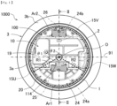
- FIG. 1 is a side view of an electric wheel system 1000 according to an embodiment of the present invention, and is a diagram of the electric wheel system 1000 as viewed from a first direction D1 of FIG. 2.
- FIG. 2 is a schematic cross-sectional view of the electric wheel system 1000, and illustrates a cross section taken along line II-II in FIG. 1 .
- the electric wheel system 1000 includes an electric wheel unit 100 constituting a power unit of a vehicle, a vehicle suspension device 30 (see FIG. 2 ) that connects a vehicle wheel 3 and a vehicle body 9, and a braking device 40 (see FIG. 2 ) that brakes the vehicle wheel 3 of a vehicle.
- the electric wheel unit 100 includes a motor 20 that outputs driving torque, and an inverter 10 that converts DC power from a power supply device (not illustrated) such as a battery into AC power in order to control the motor 20.
- the inverter 10 is attached to an end portion in an axial direction of the motor 20 with a screw or the like.
- the motor 20 and the inverter 10 are provided in a wheel 3a of the vehicle wheel 3.
- a motor 20 illustrated in FIG. 2 is a three-phase AC motor, and includes a rotor 22, a stator 23, and a motor housing 24 that supports the stator 23.
- the stator 23 includes a cylindrical stator core and a U-phase coil, a V-phase coil, and a W-phase coil mounted on the stator core.
- the rotor 22 includes a cylindrical rotor core and a permanent magnet attached to the rotor core. The rotor 22 is rotatably provided on the inner peripheral side of the stator 23 with a gap.
- a rotation shaft (hereinafter, also referred to as a rotation shaft) O.
- the rotor 22 is connected to a shaft 61.
- the shaft 61 protrudes from the motor housing 24 in the first direction D1 (right direction in the diagram).
- a hub 62 is spline-coupled to a protruding portion of the shaft 61.
- the hub 62 is fastened to the shaft 61 by a nut 63.
- the hub 62 is provided with a plurality of hub bolts 64.
- the wheel 3a is fastened to the hub 62 by a hub bolt 64 and a nut (not illustrated).
- a tire 3b is mounted on the wheel 3a.
- the vehicle wheel 3 is driven as a rotational force of the rotor 22 is transmitted to the wheel 3a.
- an "axial direction”, a “circumferential direction”, and a “radial direction” are as described below.
- the “axial direction” is a direction along the rotation axis O of the rotor 22.
- the “circumferential direction” is a direction along a rotation direction of the rotor 22, that is, a circumferential direction around the rotation axis O.
- the “radial direction” is a direction orthogonal to the rotation axis O, that is, a radial direction of a circle around the rotation axis O.
- an “inner peripheral side” refers to the inner side in the radial direction (inner diameter side)
- an “outer peripheral side” refers to the opposite direction, that is, the outer side in the radial direction (outer diameter side).
- a surface on the vehicle body side (inner side in a vehicle width direction) of the inverter 10 and the motor 20 is also referred to as a "front surface”
- a surface on the side opposite to the vehicle body side (outer side in the vehicle width direction) of the inverter 10 and the motor 20 is also referred to as a "back surface”.
- first direction D1 is a direction from the vehicle body side (inner side in the vehicle width direction) toward the side opposite to the vehicle body side (outer side in the vehicle width direction)
- second direction D2 is a direction from the side opposite to the vehicle body side (outer side in the vehicle width direction) toward the vehicle body side (inner side in the vehicle width direction).
- the vehicle suspension device 30 includes a lower arm (first arm) 31 that connects the ground side (lower side) of the electric wheel unit 100 and the vehicle body 9, an upper arm (second arm) 32 that connects a top side (upper side) of the electric wheel unit 100 and the vehicle body 9, and a suspension 33 having an upper end portion rotatably connected to the vehicle body 9 and a lower end portion rotatably connected to the lower arm 31.
- One end portion of the lower arm 31 is vertically swingably connected to the vehicle body 9, and the other end portion is rotatably connected to the motor housing 24.
- One end portion of the upper arm 32 is vertically swingably connected to the vehicle body 9, and the other end portion is rotatably connected to the motor housing 24.
- the suspension 33 includes a shock absorber 33a and a spring 33b externally mounted on the shock absorber 33a.
- the suspension 33 transmits a vehicle body load and a loading load to the vehicle wheel 3, and absorbs and attenuates an impact acting on the vehicle wheel 3 from a road surface 90.
- an end portion of a cylinder tube is connected to the lower arm 31, and a tip portion of a rod protruding upward from the cylinder tube is connected to the vehicle body 9.
- the cylinder tube of the shock absorber 33a is disposed between the lower arm 31 and the upper arm 32.
- the motor housing 24 includes a lower ball joint 25 which is a first arm connection portion connected to the lower arm 31, and an upper ball joint 26 which is a second arm connection portion connected to the upper arm 32.
- the lower ball joint 25 is attached to a lower joint attachment portion 24a provided in the motor housing 24, and the upper ball joint 26 is attached to an upper joint attachment portion 24b provided in the motor housing 24.
- the lower joint attachment portion 24a and the upper joint attachment portion 24b may be fastened to the motor housing 24 by a fastening member such as a bolt as a member separate from the motor housing 24, or may be integrally molded with the motor housing 24.
- the lower joint attachment portion 24a and the upper joint attachment portion 24b are provided so as to protrude from a surface of the motor housing 24 toward the vehicle body side.
- the upper ball joint 26 is disposed closer to the vehicle body side than the lower ball joint 25.
- the inverter 10 is disposed at a position overlapping a kingpin axis Ka that is a straight line connecting a rotation center A of the lower ball joint 25 and a rotation center B of the upper ball joint 26. More specifically, the inverter 10 is disposed at a position overlapping a line segment AB connecting the rotation center A of the lower ball joint 25 and the rotation center B of the upper ball joint 26.
- the lower arm 31 extends from the vehicle body 9 to below the inverter 10, and a tip portion of the lower arm 31 is arranged to face a lower surface portion 111 of the inverter 10.
- the lower ball joint 25 is disposed to face the lower surface portion 111 of the inverter 10 with the lower joint attachment portion 24a interposed between them.
- the lower arm 31 extends from the vehicle body side to the inside of the wheel 3a, and is connected to the motor housing 24 via the lower ball joint 25 on the lower side of the inverter 10. For this reason, a kingpin offset Ko can be made small.
- the kingpin offset Ko refers to a distance from a point Kp where the kingpin axis Ka intersects the road surface 90 to a grounding center point Cp of the tire 3b.
- the grounding center point Cp of the tire 3b refers to a point at which a center line (hereinafter, also referred to as a width center line) CL in a width direction of the tire 3b parallel to a vertical axis (axis extending in a gravity direction) intersects the road surface 90.
- the smaller the kingpin offset Ko the higher the stability of a vehicle at the time of steering of a steering wheel.
- the motor housing 24 has a circular outer shape around the rotation axis O when viewed from the first direction D1.
- the motor housing 24 includes a first sector area 1 that is a sector area having a central angle ⁇ 1 about the rotation axis O of 120°, and a second sector area 2 that is a sector area having a central angle ⁇ 2 about the rotation axis O of 240°.
- the first sector area 1 and the second sector area 2 are indicated by a thick broken line for convenience.
- the first sector area 1 is an area surrounded by a first radius R1, a second radius R2, and an arc Ar1 between the first radius R1 and the second radius R2.
- the second sector area 2 is an area surrounded by the first radius R1, the second radius R2, and an arc Ar2 between the first radius R1 and the second radius R2.
- the first sector area 1 is disposed on the ground side (lower side) of the motor housing 24, and the second sector area 2 is disposed on the top side (upper side) of the motor housing 24.
- the entire arc Ar1 of the first sector area 1 is located below a reference surface 91 that passes through the rotation axis O and is parallel to the horizontal.
- the first sector area 1 is disposed such that a center in the circumferential direction of the arc Ar1 is located further on the lower side than the reference surface 91
- the second sector area 2 is disposed such that a center in the circumferential direction of the arc Ar2 is located further on the upper side than the reference surface 91.
- the first sector area 1 and the second sector area 2 are line-symmetric with respect to a virtual plane (II-II line cross section) including the entire rotation axis O.
- outer shapes of the lower ball joint 25 and the lower joint attachment portion 24a, and the upper ball joint 25 and the upper joint attachment portion 24b are indicated by two-dot chain lines, and sizes of the outer shapes are schematically indicated by hatching.
- FIG. 1 when the electric wheel unit 100 is viewed from the axial direction, the lower ball joint 25 is disposed in the first sector area 1, and the upper ball joint 26 is disposed in the second sector area 2.
- electrical connection portions 15U, 15V, and 15W of phases between the inverter 10 and the motor 20 are disposed in the second sector area 2. Since the electrical connection portions 15U, 15V, and 15W are concentrated in the second sector area 2, the lower ball joint 25 and the lower joint attachment portion 24a provided in the first sector area 1 can be disposed close to the rotation axis O side.
- the lower ball joint 25 and the lower joint attachment portion 24a are disposed at a position closer to the rotation axis O than a lower end of the motor housing 24.
- a distance in the radial direction between the rotation center A of the lower ball joint 25 and the rotation axis O is equal to or less than half a radius of an outermost periphery of the motor 20 (an outermost periphery of the motor housing 24). Therefore, in the present embodiment, an inclination angle of the kingpin axis Ka with respect to the vertical axis can be made large as compared with a case where the lower ball joint 25 is disposed close to the lower end side of the motor housing 24.
- FIG. 3 is a diagram of the inverter 10 in a state where an inverter cover 19 is removed as viewed from the first direction D1 of FIG. 2
- FIG. 4 is a diagram of the inverter 10 as viewed from the second direction D2 of FIG. 2 .
- the inverter 10 includes a power circuit unit 11 that converts DC power into AC power, a control circuit 12 that controls the power circuit unit 11, a box-shaped inverter case 18 that houses the power circuit unit 11 and the control circuit 12, and the inverter cover 19 (see FIG. 1 ) that covers an opening portion of the inverter case 18.
- the inverter cover 19 (see FIG. 1 ) is connected to the inverter case 18 with a screw or the like.
- the inverter case 18 includes a planar back surface portion 118 disposed to face the motor housing 24 and a side plate 110 rising from the back surface portion 118 in the second direction D2.
- the side plate 110 is provided along an outer periphery of the back surface portion 118.
- the side plate 110 includes an upper surface portion 115 disposed on the top side (upper side) of the inverter case 18, the lower surface portion 111 disposed on the ground side (lower side) of the inverter case 18, and curved portions 116 and 117 connecting the upper surface portion 115 and the lower surface portion 111.
- the lower surface portion 111 is provided with a recessed portion 114 recessed upward.
- the lower surface portion 111 includes a first lower surface portion 112 and a second lower surface portion 113 provided at an end portion in a front-rear direction of a vehicle, a first side surface portion 114b extending upward from an end portion on the inverter center side of the first lower surface portion 112, a second side surface portion 114c extending upward from an end portion on the inverter center side of the second lower surface portion 113, and a bottom surface portion 114a connecting an upper end portion of the first side surface portion 114b and an upper end portion of the second side surface portion 114c.
- the recessed portion 114 is formed by the plate-shaped bottom surface portion 114a extending in the front-rear direction of a vehicle, and the first side surface portion 114b and the second side surface portion 114c extending downward from both end portions of the bottom surface portion 114a, and has a rectangular shape. As illustrated in FIG. 1 , the lower joint attachment portion 24a is disposed in the recessed portion 114.
- the power circuit unit 11 and the control circuit 12 are disposed adjacent to each other in the horizontal direction (the front-rear direction of a vehicle) orthogonal to the axial direction.
- the power circuit unit 11 is disposed on the left side of the inverter case 18 in the diagram, and the control circuit 12 is disposed on the right side of the inverter case 18.
- the power circuit unit 11 includes a plurality of switching semiconductor elements such as an insulated gate bipolar transistor (IGBT) and a plurality of diodes.
- IGBT insulated gate bipolar transistor
- the power circuit unit 11 is connected to a power supply device (not illustrated) such as a battery via a positive electrode power supply terminal 13 and a negative electrode power supply terminal 14, and electric energy necessary for driving the motor 20 is supplied from the power supply device to the power circuit unit 11.
- the power circuit unit 11 converts DC power supplied from the power supply device into AC power and supplies the AC power to the motor 20. By the above, the motor 20 rotates and a vehicle is driven.
- a series circuit of upper and lower arms is configured by an IGBT and a diode on the positive electrode side (upper arm side) and an IGBT and a diode on the negative electrode side (lower arm side).
- the upper and lower arms are configured for each phase.
- the control circuit 12 gives a drive signal to the plurality of switching semiconductor elements constituting the upper and lower arms based on a command from a host controller (not illustrated).
- the switching semiconductor element performs conduction or cutoff operation based on a drive signal from the control circuit 12, and converts DC power supplied from the power supply device into three-phase AC power.
- the converted AC power is supplied to the motor 20 via the three electrical connection portions 15U, 15V, and 15W.
- the power circuit unit 11 is provided with a smoothing capacitor (not illustrated) that smooths voltage applied to the inverter 10.
- the smoothing capacitor is electrically connected to the DC positive electrode side and the DC negative electrode side of the power circuit unit 11. Transient current generated during switching operation of a switching semiconductor element of the inverter 10 flows into the smoothing capacitor and is smoothed by the smoothing capacitor. As a result, a path of transient current at the time of switching operation is completed only in the power circuit unit 11, and inductance can be reduced as a current path is shortened.
- control circuit 12 is disposed in the immediate vicinity of the power circuit unit 11. For this reason, increase in loss can be prevented by reducing inductance of a control signal and preventing lowering in element driving performance.
- a U-phase AC terminal 15Ui, a V-phase AC terminal 15Vi, and a W-phase AC terminal 15Wi of the inverter 10 are disposed at intervals of 120° in the circumferential direction (circumferential direction around the rotation axis O).
- opening portions 118u, 118v, and 118w are provided at positions corresponding to the U-phase AC terminal 15Ui, the V-phase AC terminal 15Vi, and the W-phase AC terminal 15Wi of the inverter 10.
- FIG. 5 is a diagram of the motor 20 as viewed from the first direction D1 in FIG. 2 .
- a U-phase AC terminal 15Um, a V-phase AC terminal 15Vm, and a W-phase AC terminal 15Wm of the motor 20 are provided on a surface (surface on the vehicle body side) of the motor housing 24.
- the U-phase AC terminal 15Um, the V-phase AC terminal 15Vm, and the W-phase AC terminal 15Wm of the motor 20 are disposed at intervals of 120° in the circumferential direction (circumferential direction around the rotation axis O) in the second sector area 2 of the motor housing 24.
- the U-phase AC terminal 15Um, the V-phase AC terminal 15Vm, and the W-phase AC terminal 15Wm of the motor 20 are provided so as to protrude from a surface (surface on the vehicle body side) of the motor housing 24 toward the inverter 10.
- the inverter 10 is attached to the front surface side of the motor housing 24, the U-phase AC terminal 15Um, the V-phase AC terminal 15Vm, and the W-phase AC terminal 15Wm of the motor 20 are inserted into the opening portions 118u, 118v, and 118w provided in the back surface portion 118 of the inverter 10.
- the U-phase electrical connection portion 15U is formed as the U-phase AC terminal 15Ui (see FIG. 4 ) of the inverter 10 and the U-phase AC terminal 15Um (see FIG. 5 ) of the motor 20 are connected by screwing or the like.
- the V-phase electrical connection portion 15V is formed as the V-phase AC terminal 15Vi (see FIG. 4 ) of the inverter 10 and the V-phase AC terminal 15Vm (see FIG. 5 ) of the motor 20 are connected by screwing or the like.
- the W-phase electrical connection portion 15W is formed as the W-phase AC terminal 15Wi (see FIG. 4 ) of the inverter 10 and the W-phase AC terminal 15Wm (see FIG. 5 ) of the motor 20 are connected by screwing or the like.
- the V-phase electrical connection portion 15V is disposed on the vertical axis orthogonal to the rotation axis O, and the entire V-phase electrical connection portion 15V is disposed in the second sector area 2 when viewed from the axial direction.
- the U-phase electrical connection portion 15U and the W-phase electrical connection portion 15W are disposed so as to cross a boundary between the first sector area 1 and the second sector area 2 when viewed from the axial direction. That is, when viewed from the axial direction, a part of the U-phase electrical connection portion 15U is disposed in the first sector area 1, and the rest is disposed in the second sector area 2. Similarly, when viewed from the axial direction, a part of the W-phase electrical connection portion 15W is disposed in the first sector area 1, and the rest is disposed in the second sector area 2.
- the U-phase electrical connection portion 15U and the W-phase electrical connection portion 15W are disposed on both sides in the horizontal direction of the lower joint attachment portion 24a and the recessed portion 114. In other words, the recessed portion 114 and the lower joint attachment portion 24a are disposed between the U-phase electrical connection portion 15U and the W-phase electrical connection portion 15W.
- the power circuit unit 11 has an inverter refrigerant inlet 16 (see FIG. 3 ) for taking a refrigerant into the power circuit unit 11, an in-circuit flow path (not illustrated) through which a refrigerant flows, and an inverter refrigerant outlet 17 (see FIG. 4 ) for taking out, from the power circuit unit 11, a refrigerant having flowed through the in-circuit flow path.
- the inverter refrigerant inlet 16 is provided on the front surface side (vehicle body side) of the inverter 10, and the inverter refrigerant outlet 17 is provided on the back surface side (motor side) of the inverter 10.
- the refrigerant is, for example, vegetable oil such as palm oil, or electrically insulating oil such as mineral oil.
- the refrigerant circulates in a cooling system including a pump and a heat exchanger (not illustrated).
- a refrigerant discharged from the pump is supplied from the inverter refrigerant inlet 16 to the in-circuit flow path, directly cools each component such as a switching semiconductor element, and is discharged from the inverter refrigerant outlet 17. This makes it possible to prevent increase in thermal resistance due to increase in length of a heat dissipation path and to increase output of the inverter 10.
- the motor 20 includes a motor refrigerant inlet 28 for taking a refrigerant into the motor 20, an in-motor flow path (not illustrated) through which a refrigerant flows, and a motor refrigerant outlet 29 for taking out, from the motor 20, a refrigerant that has flowed through the in-motor flow path.
- the motor refrigerant inlet 28 and the motor refrigerant outlet 29 are provided on the front surface side (vehicle body side) of the motor 20.
- the motor refrigerant inlet 28 (see FIG. 5 ) is connected to the inverter refrigerant outlet 17 (see FIG. 4 ).
- the inverter refrigerant outlet 17 and the motor refrigerant inlet 28 have a cylindrical shape, and have tip portions abutting on each other.
- a seal member such as an O-ring is provided between the inverter refrigerant outlet 17 and the motor refrigerant inlet 28, and a gap between the inverter refrigerant outlet 17 and the motor refrigerant inlet 28 is sealed.
- the inverter 10 is screwed to the motor 20, so that the inverter refrigerant outlet 17 and the motor refrigerant inlet 28 are directly connected.
- a refrigerant discharged from the pump (not illustrated) and supplied to the in-circuit flow path (not illustrated) of the inverter 10 is supplied from the motor refrigerant inlet 28 (see FIG. 5 ) to the in-motor flow path (not illustrated) through the inverter refrigerant outlet 17, directly cools the rotor 22 and the stator 23 (see FIG. 2 ), and is discharged from the motor refrigerant outlet 29 (see FIG. 5 ).
- the refrigerant discharged from the motor refrigerant outlet 29 is cooled by a heat exchanger (not illustrated), and is supplied from the inverter refrigerant inlet 16 (see FIG. 3 ) into the inverter 10 again by a pump (not illustrated).
- a refrigerant that cools the inverter 10 is supplied to the motor 20 to cool the motor 20, and the motor 20 and the inverter 10 are cooled by a common refrigerant.
- a common cooling system is used for the inverter 10 and the motor 20
- a cooling system can be downsized and the entire electric wheel system 1000 can be downsized as compared with a case where a cooling system of the inverter 10 and a cooling system of the motor 20 are individually provided.
- the inverter 10 is attached to the front surface (surface on the vehicle body side) of the motor 20, it is not necessary to provide a pipe such as a hose connecting the inverter refrigerant outlet 17 and the motor refrigerant inlet 28.
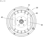
- FIG. 6 is a diagram of the motor 20 as viewed from the second direction D2 in FIG. 2 .
- the braking device 40 is disposed on the back surface side (side opposite to the vehicle body side) of the motor 20. That is, as illustrated in FIG. 2 , the braking device 40 is disposed in a space between the motor housing 24 and a spoke of the wheel 3a in the wheel 3a.
- the braking device 40 includes a brake disc 41 that rotates together with the rotor 22 and a brake caliper 42 fixed to the motor housing 24.
- the brake disc 41 is fastened together with the wheel 3a to the hub 62 by, for example, the hub bolt 64 and a nut.
- a brake pad supported by the brake caliper 42 sandwiches the brake disc 41 to brake rotation of the brake disc 41.
- rotation of the rotor 22 stops. That is, the braking device 40 can brake and stop rotation of the vehicle wheel 3.
- the inverter 10 since the inverter 10 is attached to an end portion in the axial direction of the motor 20, the motor 20 and the inverter 10 can be mounted in the wheel 3a of the vehicle wheel 3. Since power units (the motor 20 and the inverter 10) are integrated in the wheel 3a, the electric wheel system 1000 can be downsized as compared with a case where the inverter 10 is attached to a portion (for example, the upper arm 32) separate from the motor 20. As described above, in the present embodiment, since downsizing of the electric wheel system 1000 is realized, a vehicle interior space can be enlarged.
- the lower ball joint 25 can be disposed close to the rotation axis O side in the first sector area 1 on the ground side of the motor housing 24.
- the motor 20 is a three-phase AC motor, and the electrical connection portions 15U, 15V, and 15W are connection portions between AC terminals (15Um, 15Vm, and 15Wm) of three phases of the motor 20 and AC terminals (15Ui, 15Vi, and 15Wi) of three phases of the inverter 10.
- the electrical connection portions 15U, 15V, and 15W of three phases are disposed at intervals of 120° in the circumferential direction around the rotation axis O such that a part or all of the electrical connection portions 15U, 15V, and 15W are located in the second sector area 2.
- the electrical connection portions 15U, 15V, and 15W generate heat when large current is applied to a coil of the stator 23.
- the electrical connection portions 15U, 15V, and 15W are disposed to be dispersed in the circumferential direction, it is possible to effectively prevent temperature rise of the electric wheel unit 100 due to heat generation of the electrical connection portions 15U, 15V, and 15W.
- the electrical connection portions 15U, 15V, and 15W are disposed in a dispersed manner, it is possible to reduce thickness of the electric wheel unit 100.
- the inverter 10 is disposed at an end portion in the axial direction of the motor 20. For this reason, AC terminals (15Um, 15Vm, and 15Wm) of three phases of the motor 20 and AC terminals (15Ui, 15Vi, 15Wi) of three phases of the inverter 10 can be directly connected without a cable.
- a cable for connecting an AC terminal of the inverter 10 and an AC terminal of the motor 20 is required. If the cable is long, the cable may be disconnected due to shaking and vibration during traveling of a vehicle.
- an AC terminal of the inverter 10 and an AC terminal of the motor 20 are directly connected, it is possible to prevent occurrence of a failure of the electric wheel system 1000 due to disconnection of a cable.
- the inverter 10 since the inverter 10 is disposed at an end portion in the axial direction of the motor 20, maintainability can be improved. Furthermore, in the present embodiment, degree of freedom in designing the vehicle suspension device 30 and the vehicle body 9 can be improved as compared with a case where the inverter 10 is attached to a portion (for example, the upper arm 32) separate from the motor 20.
- the lower arm 31 extends from the vehicle body 9 to below the inverter 10.
- the lower ball joint 25 can be disposed close to a width center line CL of the tire 3b.
- the inverter 10 includes the power circuit unit 11 that converts DC power into AC power, the control circuit 12 that controls the power circuit unit 11, and the inverter case 18 that houses the power circuit unit 11 and the control circuit 12.
- the inverter case 18 is provided with the recessed portion 114 recessed upward on the lower surface portion 111 of the inverter case 18, and the lower joint attachment portion 24a protruding from the motor housing 24 toward the vehicle body side is disposed in the recessed portion 114.
- the lower ball joint 25 is attached to the lower joint attachment portion 24a.
- the lower ball joint 25 can be positioned on the upper side as compared with a case where the recessed portion 114 is not provided.
- the kingpin offset Ko can be further reduced.
- the kingpin offset Ko is preferably 0 (zero).
- the recessed portion 114 is provided between the U-phase electrical connection portion 15U and the W-phase electrical connection portion 15W, and both disposing the electrical connection portions 15U, 15V, and 15W of three phases dispersedly and disposing the lower ball joint 25 close to the rotation axis O are realized.
- the motor 20 and the inverter 10 are cooled by a common refrigerant.
- a common cooling system is used for the inverter 10 and the motor 20, the cooling system can be downsized, and the entire electric wheel system 1000 can be downsized.
- the electric wheel system 1000 includes the brake disc 41 that rotates together with the rotor 22 and the brake caliper 42 that stops rotation of the rotor 22 by stopping rotation of the brake disc 41, and the brake disc 41 and the brake caliper 42 are disposed in the wheel 3a. Therefore, according to the present embodiment, it is possible to provide the electric wheel system 1000 of small size in which the motor 20, the inverter 10, the brake disc 41, and the brake caliper 42 are housed in the wheel 3a.
- the electrical connection portions 15U, 15V, and 15W of the inverter 10 and the motor 20 are disposed at intervals of 120° in the circumferential direction around the rotation axis O, but the present invention is not limited to this.
- the electrical connection portions 15U, 15V, and 15W may be disposed in a horizontal line or a vertical line such that all of the electrical connection portions 15U, 15V, and 15W are located in the second sector area 2.
- the recessed portion 114 has a rectangular shape, but the present invention is not limited to this.
- the recessed portion 114 may have a curved shape such as a semicircular shape.
Landscapes
- Engineering & Computer Science (AREA)
- Power Engineering (AREA)
- Mechanical Engineering (AREA)
- Microelectronics & Electronic Packaging (AREA)
- Chemical & Material Sciences (AREA)
- Combustion & Propulsion (AREA)
- Transportation (AREA)
- Arrangement Or Mounting Of Propulsion Units For Vehicles (AREA)
- Vehicle Body Suspensions (AREA)
Abstract
Description
- The present invention relates to an electric wheel system.
- In recent years, in the automobile industry, an electric vehicle of an in-wheel motor system in which a motor (electric motor) is incorporated in a wheel of a vehicle wheel has been developed in order to improve vehicle controllability and expand a vehicle interior space. In an electric vehicle of the in-wheel motor system, it is desirable to dispose an inverter in the vicinity of a wheel from the viewpoint of simplification of a wiring cable, downsizing of a vehicle configuration, and the like.
- PTL 1 discloses an electric wheel system (vehicle driving device) including a motor that is provided in a wheel of a vehicle wheel and drives the vehicle wheel, an inverter that controls power applied to the motor, and a suspension arm provided between the vehicle wheel and a vehicle body. In this electric wheel system, the inverter is fixed to a suspension arm (upper arm) to receive traveling wind, and the suspension arm functions as a heat radiator of the inverter, so that cooling performance of the inverter is ensured.
- PTL 1:
JP 2007-161053 A - However, in the technique described in
PTL 1, since the inverter is fixed to the suspension arm and a distance between the inverter and the motor is long, there is room for improvement from the viewpoint of downsizing of the electric wheel system. Here, in a case where the inverter is disposed near the motor in order to downsize the electric wheel system, and a position of a connection portion of the suspension arm is moved away from a tire or a position of a lower arm is lowered in order to avoid interference between the inverter and the suspension arm, there is a possibility that a kingpin offset becomes large and stability of a vehicle deteriorates. - An object of the present invention is to achieve downsizing of an electric wheel system while ensuring stability of a vehicle at the time of steering.
- An electric wheel system according to one aspect of the present invention includes an electric wheel unit including a motor that is provided in a wheel of a vehicle wheel and drives the vehicle wheel, and an inverter that is attached to an end portion in an axial direction of the motor and controls the motor, a first arm that connects a ground side of the electric wheel unit and a vehicle body, and a second arm that connects a top side of the electric wheel unit and the vehicle body. The motor includes a rotor, a stator, and a motor housing that supports the stator, the motor housing includes a first arm connection portion connected to the first arm, and a second arm connection portion connected to the second arm, the inverter is disposed at a position overlapping a line segment connecting the first arm connection portion and the second arm connection portion, in a case of being viewed from a direction along a rotation axis of the rotor, the motor housing includes a first sector area having a central angle of 120° about the rotation axis and a second sector area having a central angle of 240° about the rotation axis, the first arm connection portion is disposed in the first sector area disposed on a ground side of the motor housing, and an electrical connection portion between the inverter and the motor is disposed in the second sector area disposed on a top side of the motor housing.
- According to the present invention, it is possible to achieve downsizing of an electric wheel system while ensuring stability of a vehicle at the time of steering.
-
- [
FIG. 1] FIG. 1 is a side view of an electric wheel system, and is a diagram of the electric wheel system as viewed from a first direction D1 inFIG. 2 . - [
FIG. 2] FIG. 2 is a schematic cross-sectional view of the electric wheel system, and illustrates a cross section taken along line II-II inFIG. 1 . - [
FIG. 3] FIG. 3 is a diagram of an inverter in a state in which an inverter cover is removed as viewed from the first direction D1 inFIG. 2 . - [
FIG. 4] FIG. 4 is a diagram of the inverter as viewed from a second direction D2 inFIG. 2 . - [
FIG. 5] FIG. 5 is a diagram of a motor as viewed from the first direction D1 inFIG. 2 . - [
FIG. 6] FIG. 6 is a diagram of the motor as viewed in the second direction D2 ofFIG. 2 . - Hereinafter, an electric wheel system according to an embodiment of the present invention will be described with reference to the drawings. Note that, in the drawings, the same elements are denoted by the same reference numerals, and redundant description is omitted. In description below, vertical, horizontal, front and rear directions and positions are based on an attitude in which an electric vehicle (hereinafter, also referred to as a vehicle) on which the electric wheel system is mounted travels straight on a horizontal road surface.
-
FIG. 1 is a side view of anelectric wheel system 1000 according to an embodiment of the present invention, and is a diagram of theelectric wheel system 1000 as viewed from a first direction D1 ofFIG. 2. FIG. 2 is a schematic cross-sectional view of theelectric wheel system 1000, and illustrates a cross section taken along line II-II inFIG. 1 . As illustrated inFIGS. 1 and2 , theelectric wheel system 1000 includes anelectric wheel unit 100 constituting a power unit of a vehicle, a vehicle suspension device 30 (seeFIG. 2 ) that connects avehicle wheel 3 and avehicle body 9, and a braking device 40 (seeFIG. 2 ) that brakes thevehicle wheel 3 of a vehicle. - The
electric wheel unit 100 includes amotor 20 that outputs driving torque, and aninverter 10 that converts DC power from a power supply device (not illustrated) such as a battery into AC power in order to control themotor 20. Theinverter 10 is attached to an end portion in an axial direction of themotor 20 with a screw or the like. Themotor 20 and theinverter 10 are provided in awheel 3a of thevehicle wheel 3. By integrating theelectric wheel unit 100, which is a power unit of a vehicle, in thewheel 3a, downsizing of the entireelectric wheel system 1000 is realized. As a result, a vehicle interior space can be enlarged. - A
motor 20 illustrated inFIG. 2 is a three-phase AC motor, and includes arotor 22, astator 23, and amotor housing 24 that supports thestator 23. Thestator 23 includes a cylindrical stator core and a U-phase coil, a V-phase coil, and a W-phase coil mounted on the stator core. Therotor 22 includes a cylindrical rotor core and a permanent magnet attached to the rotor core. Therotor 22 is rotatably provided on the inner peripheral side of thestator 23 with a gap. - When AC power is supplied from the
inverter 10 to a coil of each phase, a rotating magnetic field is generated, and therotor 22 rotates about a rotation center axis (hereinafter, also referred to as a rotation shaft) O. Therotor 22 is connected to ashaft 61. Theshaft 61 protrudes from themotor housing 24 in the first direction D1 (right direction in the diagram). Ahub 62 is spline-coupled to a protruding portion of theshaft 61. Thehub 62 is fastened to theshaft 61 by a nut 63. Thehub 62 is provided with a plurality ofhub bolts 64. Thewheel 3a is fastened to thehub 62 by ahub bolt 64 and a nut (not illustrated). Atire 3b is mounted on thewheel 3a. - As described above, since the
rotor 22 is connected to thewheel 3a, thevehicle wheel 3 is driven as a rotational force of therotor 22 is transmitted to thewheel 3a. - In the present description, an "axial direction", a "circumferential direction", and a "radial direction" are as described below. The "axial direction" is a direction along the rotation axis O of the
rotor 22. The "circumferential direction" is a direction along a rotation direction of therotor 22, that is, a circumferential direction around the rotation axis O. The "radial direction" is a direction orthogonal to the rotation axis O, that is, a radial direction of a circle around the rotation axis O. Further, an "inner peripheral side" refers to the inner side in the radial direction (inner diameter side), and an "outer peripheral side" refers to the opposite direction, that is, the outer side in the radial direction (outer diameter side). Furthermore, a surface on the vehicle body side (inner side in a vehicle width direction) of theinverter 10 and themotor 20 is also referred to as a "front surface", and a surface on the side opposite to the vehicle body side (outer side in the vehicle width direction) of theinverter 10 and themotor 20 is also referred to as a "back surface". Further, the first direction D1 is a direction from the vehicle body side (inner side in the vehicle width direction) toward the side opposite to the vehicle body side (outer side in the vehicle width direction), and the second direction D2 is a direction from the side opposite to the vehicle body side (outer side in the vehicle width direction) toward the vehicle body side (inner side in the vehicle width direction). - The
vehicle suspension device 30 includes a lower arm (first arm) 31 that connects the ground side (lower side) of theelectric wheel unit 100 and thevehicle body 9, an upper arm (second arm) 32 that connects a top side (upper side) of theelectric wheel unit 100 and thevehicle body 9, and asuspension 33 having an upper end portion rotatably connected to thevehicle body 9 and a lower end portion rotatably connected to thelower arm 31. One end portion of thelower arm 31 is vertically swingably connected to thevehicle body 9, and the other end portion is rotatably connected to themotor housing 24. One end portion of theupper arm 32 is vertically swingably connected to thevehicle body 9, and the other end portion is rotatably connected to themotor housing 24. - The
suspension 33 includes ashock absorber 33a and aspring 33b externally mounted on theshock absorber 33a. Thesuspension 33 transmits a vehicle body load and a loading load to thevehicle wheel 3, and absorbs and attenuates an impact acting on thevehicle wheel 3 from aroad surface 90. In the shock absorber 33a, an end portion of a cylinder tube is connected to thelower arm 31, and a tip portion of a rod protruding upward from the cylinder tube is connected to thevehicle body 9. The cylinder tube of theshock absorber 33a is disposed between thelower arm 31 and theupper arm 32. - The
motor housing 24 includes alower ball joint 25 which is a first arm connection portion connected to thelower arm 31, and anupper ball joint 26 which is a second arm connection portion connected to theupper arm 32. Thelower ball joint 25 is attached to a lowerjoint attachment portion 24a provided in themotor housing 24, and theupper ball joint 26 is attached to an upperjoint attachment portion 24b provided in themotor housing 24. - The lower
joint attachment portion 24a and the upperjoint attachment portion 24b may be fastened to themotor housing 24 by a fastening member such as a bolt as a member separate from themotor housing 24, or may be integrally molded with themotor housing 24. The lowerjoint attachment portion 24a and the upperjoint attachment portion 24b are provided so as to protrude from a surface of themotor housing 24 toward the vehicle body side. The upper ball joint 26 is disposed closer to the vehicle body side than the lower ball joint 25. - The
inverter 10 is disposed at a position overlapping a kingpin axis Ka that is a straight line connecting a rotation center A of the lower ball joint 25 and a rotation center B of the upper ball joint 26. More specifically, theinverter 10 is disposed at a position overlapping a line segment AB connecting the rotation center A of the lower ball joint 25 and the rotation center B of the upper ball joint 26. - The
lower arm 31 extends from thevehicle body 9 to below theinverter 10, and a tip portion of thelower arm 31 is arranged to face alower surface portion 111 of theinverter 10. The lower ball joint 25 is disposed to face thelower surface portion 111 of theinverter 10 with the lowerjoint attachment portion 24a interposed between them. As described above, in the present embodiment, thelower arm 31 extends from the vehicle body side to the inside of thewheel 3a, and is connected to themotor housing 24 via the lower ball joint 25 on the lower side of theinverter 10. For this reason, a kingpin offset Ko can be made small. The kingpin offset Ko refers to a distance from a point Kp where the kingpin axis Ka intersects theroad surface 90 to a grounding center point Cp of thetire 3b. The grounding center point Cp of thetire 3b refers to a point at which a center line (hereinafter, also referred to as a width center line) CL in a width direction of thetire 3b parallel to a vertical axis (axis extending in a gravity direction) intersects theroad surface 90. The smaller the kingpin offset Ko, the higher the stability of a vehicle at the time of steering of a steering wheel. - As illustrated in
FIG. 1 , themotor housing 24 has a circular outer shape around the rotation axis O when viewed from the first direction D1. In a case of being viewed from a direction along the rotation axis O of the rotor 22 (corresponding to the axial direction of the motor 20), themotor housing 24 includes afirst sector area 1 that is a sector area having a central angle θ1 about the rotation axis O of 120°, and asecond sector area 2 that is a sector area having a central angle θ2 about the rotation axis O of 240°. Thefirst sector area 1 and thesecond sector area 2 are indicated by a thick broken line for convenience. As illustrated, thefirst sector area 1 is an area surrounded by a first radius R1, a second radius R2, and an arc Ar1 between the first radius R1 and the second radius R2. Thesecond sector area 2 is an area surrounded by the first radius R1, the second radius R2, and an arc Ar2 between the first radius R1 and the second radius R2. - The
first sector area 1 is disposed on the ground side (lower side) of themotor housing 24, and thesecond sector area 2 is disposed on the top side (upper side) of themotor housing 24. When a vehicle is located on thehorizontal road surface 90, the entire arc Ar1 of thefirst sector area 1 is located below areference surface 91 that passes through the rotation axis O and is parallel to the horizontal. Thefirst sector area 1 is disposed such that a center in the circumferential direction of the arc Ar1 is located further on the lower side than thereference surface 91, and thesecond sector area 2 is disposed such that a center in the circumferential direction of the arc Ar2 is located further on the upper side than thereference surface 91. Thefirst sector area 1 and thesecond sector area 2 are line-symmetric with respect to a virtual plane (II-II line cross section) including the entire rotation axis O. - In
Fig. 1 , outer shapes of the lower ball joint 25 and the lowerjoint attachment portion 24a, and the upper ball joint 25 and the upperjoint attachment portion 24b are indicated by two-dot chain lines, and sizes of the outer shapes are schematically indicated by hatching. As illustrated inFIG. 1 , when theelectric wheel unit 100 is viewed from the axial direction, the lower ball joint 25 is disposed in thefirst sector area 1, and the upper ball joint 26 is disposed in thesecond sector area 2. - Further, when the
electric wheel unit 100 is viewed from the axial direction,electrical connection portions inverter 10 and themotor 20 are disposed in thesecond sector area 2. Since theelectrical connection portions second sector area 2, the lower ball joint 25 and the lowerjoint attachment portion 24a provided in thefirst sector area 1 can be disposed close to the rotation axis O side. - In the present embodiment, the lower ball joint 25 and the lower
joint attachment portion 24a are disposed at a position closer to the rotation axis O than a lower end of themotor housing 24. A distance in the radial direction between the rotation center A of the lower ball joint 25 and the rotation axis O is equal to or less than half a radius of an outermost periphery of the motor 20 (an outermost periphery of the motor housing 24). Therefore, in the present embodiment, an inclination angle of the kingpin axis Ka with respect to the vertical axis can be made large as compared with a case where the lower ball joint 25 is disposed close to the lower end side of themotor housing 24. By the above, since the kingpin offset Ko can be made small, stability of a vehicle at the time of steering of a steering wheel is improved. - A configuration of the
inverter 10 will be described with reference toFIGS. 1 ,3 , and4 .FIG. 3 is a diagram of theinverter 10 in a state where aninverter cover 19 is removed as viewed from the first direction D1 ofFIG. 2 , andFIG. 4 is a diagram of theinverter 10 as viewed from the second direction D2 ofFIG. 2 . As illustrated inFIG. 3 , theinverter 10 includes apower circuit unit 11 that converts DC power into AC power, acontrol circuit 12 that controls thepower circuit unit 11, a box-shapedinverter case 18 that houses thepower circuit unit 11 and thecontrol circuit 12, and the inverter cover 19 (seeFIG. 1 ) that covers an opening portion of theinverter case 18. The inverter cover 19 (seeFIG. 1 ) is connected to theinverter case 18 with a screw or the like. - As illustrated in
FIGS. 3 and4 , theinverter case 18 includes a planarback surface portion 118 disposed to face themotor housing 24 and aside plate 110 rising from theback surface portion 118 in the second direction D2. Theside plate 110 is provided along an outer periphery of theback surface portion 118. Theside plate 110 includes anupper surface portion 115 disposed on the top side (upper side) of theinverter case 18, thelower surface portion 111 disposed on the ground side (lower side) of theinverter case 18, andcurved portions upper surface portion 115 and thelower surface portion 111. Thelower surface portion 111 is provided with a recessedportion 114 recessed upward. - The
lower surface portion 111 includes a firstlower surface portion 112 and a secondlower surface portion 113 provided at an end portion in a front-rear direction of a vehicle, a firstside surface portion 114b extending upward from an end portion on the inverter center side of the firstlower surface portion 112, a secondside surface portion 114c extending upward from an end portion on the inverter center side of the secondlower surface portion 113, and abottom surface portion 114a connecting an upper end portion of the firstside surface portion 114b and an upper end portion of the secondside surface portion 114c. The recessedportion 114 is formed by the plate-shapedbottom surface portion 114a extending in the front-rear direction of a vehicle, and the firstside surface portion 114b and the secondside surface portion 114c extending downward from both end portions of thebottom surface portion 114a, and has a rectangular shape. As illustrated inFIG. 1 , the lowerjoint attachment portion 24a is disposed in the recessedportion 114. - As illustrated in
FIG. 3 , thepower circuit unit 11 and thecontrol circuit 12 are disposed adjacent to each other in the horizontal direction (the front-rear direction of a vehicle) orthogonal to the axial direction. In the example illustrated inFIG. 3 , thepower circuit unit 11 is disposed on the left side of theinverter case 18 in the diagram, and thecontrol circuit 12 is disposed on the right side of theinverter case 18. - The
power circuit unit 11 includes a plurality of switching semiconductor elements such as an insulated gate bipolar transistor (IGBT) and a plurality of diodes. - The
power circuit unit 11 is connected to a power supply device (not illustrated) such as a battery via a positive electrodepower supply terminal 13 and a negative electrodepower supply terminal 14, and electric energy necessary for driving themotor 20 is supplied from the power supply device to thepower circuit unit 11. Thepower circuit unit 11 converts DC power supplied from the power supply device into AC power and supplies the AC power to themotor 20. By the above, themotor 20 rotates and a vehicle is driven. - In the
power circuit unit 11, a series circuit of upper and lower arms is configured by an IGBT and a diode on the positive electrode side (upper arm side) and an IGBT and a diode on the negative electrode side (lower arm side). The upper and lower arms are configured for each phase. - The
control circuit 12 gives a drive signal to the plurality of switching semiconductor elements constituting the upper and lower arms based on a command from a host controller (not illustrated). The switching semiconductor element performs conduction or cutoff operation based on a drive signal from thecontrol circuit 12, and converts DC power supplied from the power supply device into three-phase AC power. The converted AC power is supplied to themotor 20 via the threeelectrical connection portions - The
power circuit unit 11 is provided with a smoothing capacitor (not illustrated) that smooths voltage applied to theinverter 10. The smoothing capacitor is electrically connected to the DC positive electrode side and the DC negative electrode side of thepower circuit unit 11. Transient current generated during switching operation of a switching semiconductor element of theinverter 10 flows into the smoothing capacitor and is smoothed by the smoothing capacitor. As a result, a path of transient current at the time of switching operation is completed only in thepower circuit unit 11, and inductance can be reduced as a current path is shortened. - Further, the
control circuit 12 is disposed in the immediate vicinity of thepower circuit unit 11. For this reason, increase in loss can be prevented by reducing inductance of a control signal and preventing lowering in element driving performance. - As illustrated in
FIG. 4 , a U-phase AC terminal 15Ui, a V-phase AC terminal 15Vi, and a W-phase AC terminal 15Wi of theinverter 10 are disposed at intervals of 120° in the circumferential direction (circumferential direction around the rotation axis O). On theback surface portion 118 of theinverter case 18, openingportions inverter 10. -
FIG. 5 is a diagram of themotor 20 as viewed from the first direction D1 inFIG. 2 . As illustrated inFIG. 5 , a U-phase AC terminal 15Um, a V-phase AC terminal 15Vm, and a W-phase AC terminal 15Wm of themotor 20 are provided on a surface (surface on the vehicle body side) of themotor housing 24. The U-phase AC terminal 15Um, the V-phase AC terminal 15Vm, and the W-phase AC terminal 15Wm of themotor 20 are disposed at intervals of 120° in the circumferential direction (circumferential direction around the rotation axis O) in thesecond sector area 2 of themotor housing 24. - The U-phase AC terminal 15Um, the V-phase AC terminal 15Vm, and the W-phase AC terminal 15Wm of the
motor 20 are provided so as to protrude from a surface (surface on the vehicle body side) of themotor housing 24 toward theinverter 10. When theinverter 10 is attached to the front surface side of themotor housing 24, the U-phase AC terminal 15Um, the V-phase AC terminal 15Vm, and the W-phase AC terminal 15Wm of themotor 20 are inserted into the openingportions back surface portion 118 of theinverter 10. - As illustrated in
FIG. 1 , the U-phaseelectrical connection portion 15U is formed as the U-phase AC terminal 15Ui (seeFIG. 4 ) of theinverter 10 and the U-phase AC terminal 15Um (seeFIG. 5 ) of themotor 20 are connected by screwing or the like. The V-phaseelectrical connection portion 15V is formed as the V-phase AC terminal 15Vi (seeFIG. 4 ) of theinverter 10 and the V-phase AC terminal 15Vm (seeFIG. 5 ) of themotor 20 are connected by screwing or the like. The W-phaseelectrical connection portion 15W is formed as the W-phase AC terminal 15Wi (seeFIG. 4 ) of theinverter 10 and the W-phase AC terminal 15Wm (seeFIG. 5 ) of themotor 20 are connected by screwing or the like. - The V-phase
electrical connection portion 15V is disposed on the vertical axis orthogonal to the rotation axis O, and the entire V-phaseelectrical connection portion 15V is disposed in thesecond sector area 2 when viewed from the axial direction. The U-phaseelectrical connection portion 15U and the W-phaseelectrical connection portion 15W are disposed so as to cross a boundary between thefirst sector area 1 and thesecond sector area 2 when viewed from the axial direction. That is, when viewed from the axial direction, a part of the U-phaseelectrical connection portion 15U is disposed in thefirst sector area 1, and the rest is disposed in thesecond sector area 2. Similarly, when viewed from the axial direction, a part of the W-phaseelectrical connection portion 15W is disposed in thefirst sector area 1, and the rest is disposed in thesecond sector area 2. - The U-phase
electrical connection portion 15U and the W-phaseelectrical connection portion 15W are disposed on both sides in the horizontal direction of the lowerjoint attachment portion 24a and the recessedportion 114. In other words, the recessedportion 114 and the lowerjoint attachment portion 24a are disposed between the U-phaseelectrical connection portion 15U and the W-phaseelectrical connection portion 15W. - As illustrated in
FIGS. 3 and4 , thepower circuit unit 11 has an inverter refrigerant inlet 16 (seeFIG. 3 ) for taking a refrigerant into thepower circuit unit 11, an in-circuit flow path (not illustrated) through which a refrigerant flows, and an inverter refrigerant outlet 17 (seeFIG. 4 ) for taking out, from thepower circuit unit 11, a refrigerant having flowed through the in-circuit flow path. Theinverter refrigerant inlet 16 is provided on the front surface side (vehicle body side) of theinverter 10, and theinverter refrigerant outlet 17 is provided on the back surface side (motor side) of theinverter 10. - The refrigerant is, for example, vegetable oil such as palm oil, or electrically insulating oil such as mineral oil. The refrigerant circulates in a cooling system including a pump and a heat exchanger (not illustrated). A refrigerant discharged from the pump is supplied from the
inverter refrigerant inlet 16 to the in-circuit flow path, directly cools each component such as a switching semiconductor element, and is discharged from theinverter refrigerant outlet 17. This makes it possible to prevent increase in thermal resistance due to increase in length of a heat dissipation path and to increase output of theinverter 10. - As illustrated in
FIG. 5 , themotor 20 includes amotor refrigerant inlet 28 for taking a refrigerant into themotor 20, an in-motor flow path (not illustrated) through which a refrigerant flows, and amotor refrigerant outlet 29 for taking out, from themotor 20, a refrigerant that has flowed through the in-motor flow path. Themotor refrigerant inlet 28 and themotor refrigerant outlet 29 are provided on the front surface side (vehicle body side) of themotor 20. - The motor refrigerant inlet 28 (see
FIG. 5 ) is connected to the inverter refrigerant outlet 17 (seeFIG. 4 ). For example, theinverter refrigerant outlet 17 and themotor refrigerant inlet 28 have a cylindrical shape, and have tip portions abutting on each other. A seal member such as an O-ring is provided between theinverter refrigerant outlet 17 and themotor refrigerant inlet 28, and a gap between theinverter refrigerant outlet 17 and themotor refrigerant inlet 28 is sealed. Theinverter 10 is screwed to themotor 20, so that theinverter refrigerant outlet 17 and themotor refrigerant inlet 28 are directly connected. - By the above, a refrigerant discharged from the pump (not illustrated) and supplied to the in-circuit flow path (not illustrated) of the
inverter 10 is supplied from the motor refrigerant inlet 28 (seeFIG. 5 ) to the in-motor flow path (not illustrated) through theinverter refrigerant outlet 17, directly cools therotor 22 and the stator 23 (seeFIG. 2 ), and is discharged from the motor refrigerant outlet 29 (seeFIG. 5 ). The refrigerant discharged from themotor refrigerant outlet 29 is cooled by a heat exchanger (not illustrated), and is supplied from the inverter refrigerant inlet 16 (seeFIG. 3 ) into theinverter 10 again by a pump (not illustrated). - Since the
rotor 22 and thestator 23 are directly cooled by a refrigerant, it is possible to increase output of themotor 20. Note that, in the present embodiment, a refrigerant that cools theinverter 10 is supplied to themotor 20 to cool themotor 20, and themotor 20 and theinverter 10 are cooled by a common refrigerant. In the present embodiment, since a common cooling system is used for theinverter 10 and themotor 20, a cooling system can be downsized and the entireelectric wheel system 1000 can be downsized as compared with a case where a cooling system of theinverter 10 and a cooling system of themotor 20 are individually provided. Further, since theinverter 10 is attached to the front surface (surface on the vehicle body side) of themotor 20, it is not necessary to provide a pipe such as a hose connecting theinverter refrigerant outlet 17 and themotor refrigerant inlet 28. -
FIG. 6 is a diagram of themotor 20 as viewed from the second direction D2 inFIG. 2 . As illustrated inFIG. 6 , thebraking device 40 is disposed on the back surface side (side opposite to the vehicle body side) of themotor 20. That is, as illustrated inFIG. 2 , thebraking device 40 is disposed in a space between themotor housing 24 and a spoke of thewheel 3a in thewheel 3a. As illustrated inFIG. 6 , thebraking device 40 includes abrake disc 41 that rotates together with therotor 22 and abrake caliper 42 fixed to themotor housing 24. Thebrake disc 41 is fastened together with thewheel 3a to thehub 62 by, for example, thehub bolt 64 and a nut. A brake pad supported by thebrake caliper 42 sandwiches thebrake disc 41 to brake rotation of thebrake disc 41. When thebrake caliper 42 stops rotation of thebrake disc 41, rotation of therotor 22 stops. That is, thebraking device 40 can brake and stop rotation of thevehicle wheel 3. - According to the above-described embodiment, a function and an effect described below are obtained.
-
- (1) The
electric wheel system 1000 includes theelectric wheel unit 100 including themotor 20 that is provided in thewheel 3a of thevehicle wheel 3 and drives thevehicle wheel 3, and theinverter 10 that is attached to an end portion in the axial direction of themotor 20 and controls themotor 20, the lower arm (first arm) 31 that connects a ground side of theelectric wheel unit 100 and thevehicle body 9, and the upper arm (second arm) 32 that connects a top side of theelectric wheel unit 100 and thevehicle body 9. Themotor 20 includes therotor 22, thestator 23, and themotor housing 24 that supports thestator 23. Themotor housing 24 includes the lower ball joint (first arm connection portion) 25 connected to thelower arm 31 and the upper ball joint (second arm connection portion) 26 connected to theupper arm 32. Theinverter 10 is disposed at a position overlapping the line segment AB connecting the lower ball joint 25 and the upper ball joint 26. In a case of being viewed from a direction along the rotation axis O of therotor 22, themotor housing 24 has thefirst sector area 1 in which the central angle θ1 about the rotation axis O is 120° and thesecond sector area 2 in which the central angle θ2 about the rotation axis O is 240°. Thefirst sector area 1 is disposed on the ground side (lower side) of themotor housing 24, and thesecond sector area 2 is disposed on the top side (upper side) of themotor housing 24. The lower ball joint 25 is disposed in thefirst sector area 1, and theelectrical connection portions inverter 10 and themotor 20 are disposed in thesecond sector area 2. - In this configuration, since the
inverter 10 is attached to an end portion in the axial direction of themotor 20, themotor 20 and theinverter 10 can be mounted in thewheel 3a of thevehicle wheel 3. Since power units (themotor 20 and the inverter 10) are integrated in thewheel 3a, theelectric wheel system 1000 can be downsized as compared with a case where theinverter 10 is attached to a portion (for example, the upper arm 32) separate from themotor 20. As described above, in the present embodiment, since downsizing of theelectric wheel system 1000 is realized, a vehicle interior space can be enlarged. - Further, since the
electrical connection portions second sector area 2 on the top side of themotor housing 24, the lower ball joint 25 can be disposed close to the rotation axis O side in thefirst sector area 1 on the ground side of themotor housing 24. By the above, since the kingpin offset Ko can be made small, stability of a vehicle at the time of steering can be improved. That is, according to the present embodiment, it is possible to downsize theelectric wheel system 1000 while ensuring stability of a vehicle at the time of steering. - (2) The
motor 20 is a three-phase AC motor, and theelectrical connection portions motor 20 and AC terminals (15Ui, 15Vi, and 15Wi) of three phases of theinverter 10. Theelectrical connection portions electrical connection portions second sector area 2. - The
electrical connection portions stator 23. In the present embodiment, since theelectrical connection portions electric wheel unit 100 due to heat generation of theelectrical connection portions electrical connection portions electric wheel unit 100. - (3) The
inverter 10 is disposed at an end portion in the axial direction of themotor 20. For this reason, AC terminals (15Um, 15Vm, and 15Wm) of three phases of themotor 20 and AC terminals (15Ui, 15Vi, 15Wi) of three phases of theinverter 10 can be directly connected without a cable. In a case where theinverter 10 is attached to a portion (for example, the upper arm 32) separate from themotor 20, a cable for connecting an AC terminal of theinverter 10 and an AC terminal of themotor 20 is required. If the cable is long, the cable may be disconnected due to shaking and vibration during traveling of a vehicle. On the other hand, in the present embodiment, since an AC terminal of theinverter 10 and an AC terminal of themotor 20 are directly connected, it is possible to prevent occurrence of a failure of theelectric wheel system 1000 due to disconnection of a cable. - Further, in the present embodiment, since the
inverter 10 is disposed at an end portion in the axial direction of themotor 20, maintainability can be improved. Furthermore, in the present embodiment, degree of freedom in designing thevehicle suspension device 30 and thevehicle body 9 can be improved as compared with a case where theinverter 10 is attached to a portion (for example, the upper arm 32) separate from themotor 20. - (4) The
lower arm 31 extends from thevehicle body 9 to below theinverter 10. In this configuration, the lower ball joint 25 can be disposed close to a width center line CL of thetire 3b. By the above, since an inclination angle of the kingpin axis Ka with respect to the vertical axis can be made large, the kingpin offset Ko can be further reduced. - (5) The
inverter 10 includes thepower circuit unit 11 that converts DC power into AC power, thecontrol circuit 12 that controls thepower circuit unit 11, and theinverter case 18 that houses thepower circuit unit 11 and thecontrol circuit 12. Theinverter case 18 is provided with the recessedportion 114 recessed upward on thelower surface portion 111 of theinverter case 18, and the lowerjoint attachment portion 24a protruding from themotor housing 24 toward the vehicle body side is disposed in the recessedportion 114. The lower ball joint 25 is attached to the lowerjoint attachment portion 24a. - In this configuration, the lower ball joint 25 can be positioned on the upper side as compared with a case where the recessed
portion 114 is not provided. In the present embodiment, since the lower ball joint 25 can be disposed close to the rotation axis O, the kingpin offset Ko can be further reduced. By the above, stability of a vehicle at the time of steering can be further enhanced. - Note that stability of a vehicle at the time of steering is improved as the kingpin offset Ko is smaller. For this reason, the kingpin offset Ko is preferably 0 (zero). As a position of the lower ball joint 25 is set so that the kingpin axis Ka and the grounding center point Cp of the
tire 3b overlap each other, stability of a vehicle at the time of steering can be enhanced. - In the present embodiment, the recessed
portion 114 is provided between the U-phaseelectrical connection portion 15U and the W-phaseelectrical connection portion 15W, and both disposing theelectrical connection portions - (6) The
motor 20 and theinverter 10 are cooled by a common refrigerant. As a common cooling system is used for theinverter 10 and themotor 20, the cooling system can be downsized, and the entireelectric wheel system 1000 can be downsized. - (7) The
electric wheel system 1000 includes thebrake disc 41 that rotates together with therotor 22 and thebrake caliper 42 that stops rotation of therotor 22 by stopping rotation of thebrake disc 41, and thebrake disc 41 and thebrake caliper 42 are disposed in thewheel 3a. Therefore, according to the present embodiment, it is possible to provide theelectric wheel system 1000 of small size in which themotor 20, theinverter 10, thebrake disc 41, and thebrake caliper 42 are housed in thewheel 3a. - Variations described below are also within the scope of the present invention, and it is also possible to combine a configuration illustrated in the variations with a configuration described in the above-described embodiment, or combine configurations described in different ones of the variations described below.
- In the above embodiment, an example in which the
electrical connection portions inverter 10 and themotor 20 are disposed at intervals of 120° in the circumferential direction around the rotation axis O, but the present invention is not limited to this. For example, theelectrical connection portions electrical connection portions second sector area 2. - <Second variation>
- In the above embodiment, an example in which the recessed
portion 114 has a rectangular shape is described, but the present invention is not limited to this. For example, the recessedportion 114 may have a curved shape such as a semicircular shape. - Although the embodiment of the present invention is described above, the above embodiment merely illustrates a part of an application example of the present invention, and a technical scope of the present invention is not intended to be limited to a specific configuration of the above embodiment. Reference Signs List
-
- 1
- first sector area
- 2
- second sector area
- 3
- vehicle wheel
- 3a
- wheel
- 3b
- tire
- 9
- vehicle body
- 10
- inverter
- 11
- power circuit unit
- 12
- control circuit
- 15U, 15V, 15W
- electrical connection portion
- 15Ui
- U-phase AC terminal of inverter
- 15Um
- U-phase AC terminal of motor
- 15Vi
- V-phase AC terminal of inverter
- 15Vm
- V-phase AC terminal of motor
- 15Wi
- W-phase AC terminal of inverter
- 15Wm
- W-phase AC terminal of motor
- 16
- inverter refrigerant inlet
- 17
- inverter refrigerant outlet
- 18
- inverter case
- 19
- inverter cover
- 20
- motor
- 22
- rotor
- 23
- stator
- 24
- motor housing
- 24a
- lower joint attachment portion
- 24b
- upper joint attachment portion
- 25
- lower ball joint (first arm connection portion)
- 26
- upper ball joint (second arm connection portion)
- 28
- motor refrigerant inlet
- 29
- motor refrigerant outlet
- 30
- vehicle suspension device
- 31
- lower arm (first arm)
- 32
- upper arm (second arm)
- 33
- suspension
- 33a
- shock absorber
- 40
- braking device
- 41
- brake disc
- 42
- brake caliper
- 100
- electric wheel unit
- 110
- side plate
- 111
- lower surface portion
- 114
- recessed portion
- 118
- back surface portion
- 118u, 118v, 118w
- opening portion
- 1000
- electric wheel system
- A, B
- rotation center
- AB
- line segment
- Ka
- kingpin axis
- Ko
- kingpin offset
- O
- rotation axis
Claims (6)
- An electric wheel system comprising:an electric wheel unit including a motor that is provided in a wheel of a vehicle wheel and drives the vehicle wheel, and an inverter that is attached to an end portion in an axial direction of the motor and controls the motor;a first arm that connects a ground side of the electric wheel unit and a vehicle body; anda second arm that connects a top side of the electric wheel unit and the vehicle body,wherein the motor includes a rotor, a stator, and a motor housing that supports the stator,the motor housing includes:a first arm connection portion connected to the first arm; anda second arm connection portion connected to the second arm,the inverter is disposed at a position overlapping a line segment connecting the first arm connection portion and the second arm connection portion,in a case of being viewed from a direction along a rotation axis of the rotor, the motor housing includes a first sector area having a central angle of 120° about the rotation axis and a second sector area having a central angle of 240° about the rotation axis,the first arm connection portion is disposed in the first sector area disposed on a ground side of the motor housing, andan electrical connection portion between the inverter and the motor is disposed in the second sector area disposed on a top side of the motor housing.
- The electric wheel system according to claim 1, whereinthe electrical connection portion is a connection portion between AC terminals of three phases of the motor and AC terminals of three phases of the inverter, andthe electrical connection portions of three phases are disposed at intervals of 120° in a circumferential direction around the rotation axis such that a part or all of the electrical connection portions are located in the second sector area.
- The electric wheel system according to claim 1, wherein the first arm extends from the vehicle body to below the inverter.
- The electric wheel system according to claim 1, whereinthe inverter includes a power circuit unit that converts DC power into AC power, a control circuit that controls the power circuit unit, and an inverter case that houses the power circuit unit and the control circuit,the first arm connection portion is a ball joint,the inverter case is provided with a recessed portion recessed upward on a lower surface portion thereof,an attachment portion protruding from the motor housing toward a side of the vehicle body is disposed in the recessed portion, andthe ball joint is attached to the attachment portion.
- The electric wheel system according to claim 1, wherein the motor and the inverter are cooled by a common refrigerant.
- The electric wheel system according to claim 1, further comprising:a brake disc that rotates together with the rotor; anda brake caliper that stops rotation of the rotor by stopping rotation of the brake disc,wherein the brake disc and the brake caliper are disposed in the wheel.
Applications Claiming Priority (2)
| Application Number | Priority Date | Filing Date | Title |
|---|---|---|---|
| JP2021111239A JP7570982B2 (en) | 2021-07-05 | 2021-07-05 | Electric Wheel System |
| PCT/JP2022/022992 WO2023281964A1 (en) | 2021-07-05 | 2022-06-07 | Electric wheel system |
Publications (3)
| Publication Number | Publication Date |
|---|---|
| EP4321363A1 true EP4321363A1 (en) | 2024-02-14 |
| EP4321363A4 EP4321363A4 (en) | 2025-06-18 |
| EP4321363B1 EP4321363B1 (en) | 2026-04-22 |
Family
ID=84800595
Family Applications (1)
| Application Number | Title | Priority Date | Filing Date |
|---|---|---|---|
| EP22837383.3A Active EP4321363B1 (en) | 2021-07-05 | 2022-06-07 | Electric wheel system |
Country Status (3)
| Country | Link |
|---|---|
| EP (1) | EP4321363B1 (en) |
| JP (1) | JP7570982B2 (en) |
| WO (1) | WO2023281964A1 (en) |
Families Citing this family (1)
| Publication number | Priority date | Publication date | Assignee | Title |
|---|---|---|---|---|
| JP7583691B2 (en) * | 2021-08-31 | 2024-11-14 | 株式会社日立製作所 | In-wheel motor |
Family Cites Families (8)
| Publication number | Priority date | Publication date | Assignee | Title |
|---|---|---|---|---|
| JP4758217B2 (en) | 2005-12-13 | 2011-08-24 | トヨタ自動車株式会社 | Vehicle drive device and electric vehicle |
| DE102011081120A1 (en) | 2011-07-07 | 2013-01-10 | Schaeffler Technologies AG & Co. KG | Sealed drive system |
| DE102011081503B4 (en) | 2011-08-24 | 2013-09-12 | Schaeffler Technologies AG & Co. KG | Wheel hub drive system |
| JP2014189036A (en) | 2013-03-26 | 2014-10-06 | Aisin Aw Co Ltd | Vehicle propulsion unit |
| JP2015073370A (en) * | 2013-10-03 | 2015-04-16 | 日産自動車株式会社 | Drive unit, and assembly method for drive unit |
| US10479207B2 (en) | 2015-07-07 | 2019-11-19 | Nissan Motor Co., Ltd. | Arrangement structure of wheel drive system |
| JP7133760B2 (en) * | 2018-11-15 | 2022-09-09 | 株式会社アドヴィックス | Vehicle drum brake and vehicle in-wheel structure |
| JP2021045988A (en) * | 2019-09-17 | 2021-03-25 | 株式会社日立製作所 | Electric device in wheel |
-
2021
- 2021-07-05 JP JP2021111239A patent/JP7570982B2/en active Active
-
2022
- 2022-06-07 WO PCT/JP2022/022992 patent/WO2023281964A1/en not_active Ceased
- 2022-06-07 EP EP22837383.3A patent/EP4321363B1/en active Active
Also Published As
| Publication number | Publication date |
|---|---|
| EP4321363A4 (en) | 2025-06-18 |
| EP4321363B1 (en) | 2026-04-22 |
| JP7570982B2 (en) | 2024-10-22 |
| JP2023008017A (en) | 2023-01-19 |
| WO2023281964A1 (en) | 2023-01-12 |
Similar Documents
| Publication | Publication Date | Title |
|---|---|---|
| US11870326B2 (en) | Electric drive apparatus, and electric power steering apparatus | |
| CN111845921B (en) | Electric drive device | |
| CN105515281B (en) | The electric machine of vehicle | |
| CN107921997B (en) | Electric drive device and electric power steering device | |
| CN107921998B (en) | Electric drive and electric power steering | |
| US11577774B2 (en) | Electric drive device and electric power steering device | |
| CN107921996B (en) | Electric drive device and electric power steering device | |
| US11407443B2 (en) | Electric drive device and electric power steering device | |
| JP2019022414A (en) | Electric drive device and electric power steering device | |
| JP2021093822A (en) | Electric drive device and electric steering device | |
| US11381131B2 (en) | Electric drive device and electric power steering device | |
| CN110710087A (en) | Electric drive device and electric power steering device | |
| WO2022149366A1 (en) | Electric power converting device | |
| US20190193775A1 (en) | Electromotive Drive Device and Electrically-Powered Steering Device | |
| JP6723201B2 (en) | Electric drive device and electric power steering device | |
| EP4321363B1 (en) | Electric wheel system | |
| JP6864029B2 (en) | Electric drive | |
| JPWO2017006429A1 (en) | Wheel drive arrangement | |
| CN121510461A (en) | Circuit boards, motor controllers, motors, motor assemblies, and vehicles | |
| JP2021191025A (en) | Power converter |
Legal Events
| Date | Code | Title | Description |
|---|---|---|---|
| STAA | Information on the status of an ep patent application or granted ep patent |
Free format text: STATUS: THE INTERNATIONAL PUBLICATION HAS BEEN MADE |
|
| PUAI | Public reference made under article 153(3) epc to a published international application that has entered the european phase |
Free format text: ORIGINAL CODE: 0009012 |
|
| STAA | Information on the status of an ep patent application or granted ep patent |
Free format text: STATUS: REQUEST FOR EXAMINATION WAS MADE |
|
| 17P | Request for examination filed |
Effective date: 20231107 |
|
| AK | Designated contracting states |
Kind code of ref document: A1 Designated state(s): AL AT BE BG CH CY CZ DE DK EE ES FI FR GB GR HR HU IE IS IT LI LT LU LV MC MK MT NL NO PL PT RO RS SE SI SK SM TR |
|
| DAV | Request for validation of the european patent (deleted) | ||
| DAX | Request for extension of the european patent (deleted) | ||
| A4 | Supplementary search report drawn up and despatched |
Effective date: 20250520 |
|
| RIC1 | Information provided on ipc code assigned before grant |
Ipc: B60G 7/00 20060101ALI20250514BHEP Ipc: B60K 7/00 20060101AFI20250514BHEP |
|
| GRAP | Despatch of communication of intention to grant a patent |
Free format text: ORIGINAL CODE: EPIDOSNIGR1 |
|
| STAA | Information on the status of an ep patent application or granted ep patent |
Free format text: STATUS: GRANT OF PATENT IS INTENDED |
|
| INTG | Intention to grant announced |
Effective date: 20260116 |
|
| GRAS | Grant fee paid |
Free format text: ORIGINAL CODE: EPIDOSNIGR3 |
|
| GRAA | (expected) grant |
Free format text: ORIGINAL CODE: 0009210 |
|
| STAA | Information on the status of an ep patent application or granted ep patent |
Free format text: STATUS: THE PATENT HAS BEEN GRANTED |
|
| AK | Designated contracting states |
Kind code of ref document: B1 Designated state(s): AL AT BE BG CH CY CZ DE DK EE ES FI FR GB GR HR HU IE IS IT LI LT LU LV MC MK MT NL NO PL PT RO RS SE SI SK SM TR |
|
| REG | Reference to a national code |
Ref country code: CH Ref legal event code: F10 Free format text: ST27 STATUS EVENT CODE: U-0-0-F10-F00 (AS PROVIDED BY THE NATIONAL OFFICE) Effective date: 20260422 Ref country code: GB Ref legal event code: FG4D |