EP4321288A1 - Hacksaw - Google Patents
Hacksaw Download PDFInfo
- Publication number
- EP4321288A1 EP4321288A1 EP23188426.3A EP23188426A EP4321288A1 EP 4321288 A1 EP4321288 A1 EP 4321288A1 EP 23188426 A EP23188426 A EP 23188426A EP 4321288 A1 EP4321288 A1 EP 4321288A1
- Authority
- EP
- European Patent Office
- Prior art keywords
- hacksaw
- blade
- handle
- support arm
- Prior art date
- Legal status (The legal status is an assumption and is not a legal conclusion. Google has not performed a legal analysis and makes no representation as to the accuracy of the status listed.)
- Pending
Links
- 238000013037 co-molding Methods 0.000 description 1
- 238000010276 construction Methods 0.000 description 1
- 230000008878 coupling Effects 0.000 description 1
- 238000010168 coupling process Methods 0.000 description 1
- 238000005859 coupling reaction Methods 0.000 description 1
- 238000003780 insertion Methods 0.000 description 1
- 230000037431 insertion Effects 0.000 description 1
- 239000000463 material Substances 0.000 description 1
- 229910052751 metal Inorganic materials 0.000 description 1
- 239000002184 metal Substances 0.000 description 1
- 150000002739 metals Chemical class 0.000 description 1
- 238000012986 modification Methods 0.000 description 1
- 230000004048 modification Effects 0.000 description 1
- 238000000465 moulding Methods 0.000 description 1
- 229920003023 plastic Polymers 0.000 description 1
- 239000004033 plastic Substances 0.000 description 1
- -1 woods Substances 0.000 description 1
Images




Classifications
-
- B—PERFORMING OPERATIONS; TRANSPORTING
- B23—MACHINE TOOLS; METAL-WORKING NOT OTHERWISE PROVIDED FOR
- B23D—PLANING; SLOTTING; SHEARING; BROACHING; SAWING; FILING; SCRAPING; LIKE OPERATIONS FOR WORKING METAL BY REMOVING MATERIAL, NOT OTHERWISE PROVIDED FOR
- B23D49/00—Machines or devices for sawing with straight reciprocating saw blades, e.g. hacksaws
- B23D49/10—Hand-held or hand-operated sawing devices with straight saw blades
- B23D49/12—Hacksaws
-
- B—PERFORMING OPERATIONS; TRANSPORTING
- B23—MACHINE TOOLS; METAL-WORKING NOT OTHERWISE PROVIDED FOR
- B23D—PLANING; SLOTTING; SHEARING; BROACHING; SAWING; FILING; SCRAPING; LIKE OPERATIONS FOR WORKING METAL BY REMOVING MATERIAL, NOT OTHERWISE PROVIDED FOR
- B23D51/00—Sawing machines or sawing devices working with straight blades, characterised only by constructional features of particular parts; Carrying or attaching means for tools, covered by this subclass, which are connected to a carrier at both ends
- B23D51/08—Sawing machines or sawing devices working with straight blades, characterised only by constructional features of particular parts; Carrying or attaching means for tools, covered by this subclass, which are connected to a carrier at both ends of devices for mounting straight saw blades or other tools
- B23D51/12—Sawing machines or sawing devices working with straight blades, characterised only by constructional features of particular parts; Carrying or attaching means for tools, covered by this subclass, which are connected to a carrier at both ends of devices for mounting straight saw blades or other tools for use with tools, dealt with in this subclass, which are connected to a carrier at both ends, e.g. bows adjustable in length or height
- B23D51/14—Attachment of the tool
-
- B—PERFORMING OPERATIONS; TRANSPORTING
- B27—WORKING OR PRESERVING WOOD OR SIMILAR MATERIAL; NAILING OR STAPLING MACHINES IN GENERAL
- B27B—SAWS FOR WOOD OR SIMILAR MATERIAL; COMPONENTS OR ACCESSORIES THEREFOR
- B27B27/00—Guide fences or stops for timber in saw mills or sawing machines; Measuring equipment thereon
- B27B27/02—Guide fences or stops for timber in saw mills or sawing machines; Measuring equipment thereon arranged laterally and parallel with respect to the plane of the saw blade
-
- B—PERFORMING OPERATIONS; TRANSPORTING
- B23—MACHINE TOOLS; METAL-WORKING NOT OTHERWISE PROVIDED FOR
- B23D—PLANING; SLOTTING; SHEARING; BROACHING; SAWING; FILING; SCRAPING; LIKE OPERATIONS FOR WORKING METAL BY REMOVING MATERIAL, NOT OTHERWISE PROVIDED FOR
- B23D51/00—Sawing machines or sawing devices working with straight blades, characterised only by constructional features of particular parts; Carrying or attaching means for tools, covered by this subclass, which are connected to a carrier at both ends
- B23D51/01—Sawing machines or sawing devices working with straight blades, characterised only by constructional features of particular parts; Carrying or attaching means for tools, covered by this subclass, which are connected to a carrier at both ends characterised by the handle
Definitions
- the present disclosure relates to cutting tools, and more particularly to hacksaws or the like.
- hacksaws include a handle, a support arm extending from the handle, and a blade.
- the blade includes a first end that is supported by the handle and a second end opposite the first end that is supported by the support arm.
- hacksaws are used to cut a number of different materials, such as plastics, woods, and metals.
- a hacksaw in one independent aspect, includes a handle defining a pocket shaped to receive a hacksaw blade without a tang and a reciprocating blade having a tang and a hole.
- the hacksaw further includes a support arm extending from the handle and a clamp mechanism coupled to the support arm and configured to hold the hacksaw blade or the reciprocating blade depending on which blade is coupled to the handle.
- a hacksaw in another independent aspect, includes a handle, a support arm extending from the handle and including a first end coupled to the handle and a second end defining a suspended support having a free end, and a clamp mechanism coupled to the suspended support adjacent the free end.
- the clamp mechanism includes an actuator and a clamp member pivotable relative to the suspended support by actuation of the actuator between a clamped state and an unclamped state to selectively clamp a blade supported by the handle.
- a hacksaw in yet another independent aspect, includes a handle defining a longitudinal axis and including a pocket for receiving a blade.
- the pocket includes a longitudinal portion that extends through the handle along the longitudinal axis and a tang portion that extends from the longitudinal portion.
- the hacksaw further includes a support arm extending from the handle and a clamp mechanism configured to secure a blade to the hacksaw.
- the longitudinal portion of the pocket of the handle is defined by a first wall and a second wall, and the first wall is oriented at an oblique angle relative to the longitudinal axis.
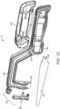
- FIGS. 1A-1C illustrate a hacksaw 10 including a handle 14 that defines a longitudinal axis A1 and a support arm 18 that extends from the handle 14.
- the handle includes a grip 14a and a frame 14b.
- the support arm 18 includes a first end 18a that is coupled to the handle 14, a second or distal end 18b opposite the first end 18a, and a middle portion 18c extending between the first end 18a and the second end 18b.
- the frame 14b is formed integrally with the support arm 18, and the illustrated grip 14a may be over-molded with the frame 14b.
- the support arm 18 is generally C-shaped such that the middle portion 18c is offset from and extends parallel to, or substantially parallel to, the longitudinal axis A1, and the second end 18b of the support arm 18 terminates adjacent or at the longitudinal axis A1.
- the hacksaw 10 further includes a reciprocating blade 22 that is removably coupled to the handle 14 and the support arm 18.
- the reciprocating blade 22 includes a first end that is received within the handle 14 and a second end opposite the first end.
- a clamp mechanism 26 is coupled to the support arm 18 adjacent or at the second end 18b to selectively secure the second end of the reciprocating blade 22 to the support arm 18.
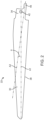
- the reciprocating blade 22 includes a cutting body 30 and an attachment portion 34 extending from the cutting body 30.
- the cutting body 30 includes a plurality of teeth that define a cutting edge 38 of the cutting body 30.
- the attachment portion 34 includes an aperture 42 and a tang 46 that defines a tang axis A2.
- the tang axis A2 extends at an oblique angle ⁇ relative to the longitudinal axis A1.
- the clamp mechanism 26 includes a clamp member 50, a pivot pin 54, and an actuator 58.
- the clamp member 50 includes a grip end 50a and a lever end 50b opposite the grip end 50a.
- the grip end 50a includes a width D1 that is wider in a dimension than a width D2 of the lever end 50b (and wider than any other portion of the clamp member 50).
- a plurality of protrusions 50c project from a face of the grip end 50a.
- the clamp member 50 further includes an aperture 50d that defines a pivot axis A3 of the clamp member 50.
- the aperture 50d (and therefore the pivot axis A3) is closer to the grip end 50a than the lever end 50b.
- the pivot pin 54 extends through the aperture 50d, and the illustrated actuator 58 includes a screw or bolt 58a and a knob 58b that is coupled to the screw 58a (e.g., by molding or co-molding, etc.).
- the knob 58b includes at least one projecting portion 58c to facilitate manipulation and rotation of the actuator 58 by a user.
- the knob 58b includes three projecting portions 58c.
- the support arm 18 of the hacksaw 10 includes a clamp support 62 that has a first rail 62a and a second rail 62b cooperatively defining a channel 62c.
- Each rail 62a, 62b includes a hole 66 that is parallel to the longitudinal axis A1 and that supports the pivot pin 54.
- the support arm 18 further includes a threaded hole 70 extending along an actuation axis A4 perpendicular to the longitudinal axis A1 and transverse to the channel 62c.
- the clamp member 50 is disposed in the channel 62c of such that the grip end 50a terminates adjacent or at the second end 18b of the support arm 18 (below the rails 62a, 62b as viewed in FIG. 3A ).
- the pivot pin 54 extends through the holes 66 of the rails 62a, 62b and the aperture 50d of the clamp member 50 such that the clamp member 50 can pivot relative to the support arm 18 about the pivot axis A3 between a clamped position ( FIG. 3D ) and an unclamped position ( FIG. 3E ).
- the screw 58a is threadably engaged with the threaded hole 70 of the support arm 18 such that the screw 58a is positioned to abut the lever end 50b of the clamp member 50.
- a user may rotate the knob 58b to move the screw 58a axially along the actuation axis A4 to pivot the clamp member 50 between the clamped position and the unclamped position.
- rotation of the knob 58b clockwise moves the clamp member 50 toward the clamped position
- rotation of the knob 58b counterclockwise moves the clamp member 50 toward the unclamped position.
- the grip end 50a of the clamp member 50 is spaced from the second end 18b of the support arm 18 by a sufficient distance (i.e.
- the grip end 50a is positioned in close proximity to the second end 18b of the support arm 18 (i.e. a distance that is about the same, or is the same, as the thickness of the blade at the front end) to clamp and secure the blade 22 between the grip end 50a of the clamp mechanism 26 and the second end 18b of the support arm 18.
- the protrusions 50c increase a clamp or grip strength between the reciprocating blade 22 and the grip end 50a.
- the handle 14 includes a pocket 74 that is defined in the frame 14b and that is shaped to receive the attachment portion 34 of a selected blade 22.
- the pocket 74 includes a longitudinal portion 74a that extends through the handle 14 along the longitudinal axis A1 (e.g., through most of the handle 14), and a tang portion 74b that extends from the longitudinal portion 74a away from the longitudinal axis A1 (e.g., downward and rightward as viewed in FIGS. 4A, 4B ).
- a longitudinal portion 74a that extends through the handle 14 along the longitudinal axis A1 (e.g., through most of the handle 14)
- a tang portion 74b that extends from the longitudinal portion 74a away from the longitudinal axis A1 (e.g., downward and rightward as viewed in FIGS. 4A, 4B ).
- the tang portion 74b is defined by a first wall 78 that is oriented at a first oblique wall angle ⁇ relative to the longitudinal axis A1 and a second wall 82 that is oriented at a second oblique wall angle ⁇ relative to the longitudinal axis A1.
- the second wall 82 may be perpendicular to the longitudinal axis A1.
- the tang portion 74b may be partially defined by a chamfered surface 86 between the first wall 78 and the second wall 82.
- the attachment portion 34 of the reciprocating blade 22 is received within the pocket 74 when the reciprocating blade 22 is secured to the hacksaw 10 by the clamp mechanism 26.
- the tang 46 extends into the tang portion 74b.
- some reciprocating blades are not coupled to the hacksaw 10 by simply sliding the attachment portion of the reciprocating blade into the pocket 74.
- the reciprocating blade 22 is coupled to the hacksaw 10 by sequentially sliding the attachment portion 34 into the pocket 74, pivoting the attachment portion 34 within the pocket 74 so that the tang 46 moves toward the tang portion 74b, and clamping the reciprocating blade 22 to the support arm 18 via the clamp mechanism 26
- the tang portion 74b of the pocket 74 is sized to receive blade tangs that have varying sizes, shapes, and tang axes.
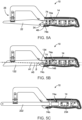
- the pocket 74 is sized to receive an attachment portion 134 of a second reciprocating blade 122 that includes a tang 146 with a second tang axis A5 extending at an angle ⁇ relative to the longitudinal axis A1.
- the angle ⁇ is different from the tang axis ⁇
- the tang 146 is different from the shape or angle of the tang 46 of the blade 22.
- the pocket 74 shaped to accommodate different blades, including different reciprocating blades so that the hacksaw 10 can be used with blades that vary in both size and shape where the blades connect to the handle 14.
- the pocket 74 is also sized to accommodate and couple a standard hacksaw blade 222 to the handle 14.
- the hacksaw blade 222 has an attachment portion 234 without a tang, and the hacksaw blade 222 extends farther into the longitudinal portion 74a of the pocket 74 than the reciprocating blades 22, 122.
- the hacksaw 10 may be used with a variety of reciprocating blades and standard blades.
Landscapes
- Engineering & Computer Science (AREA)
- Mechanical Engineering (AREA)
- Life Sciences & Earth Sciences (AREA)
- Wood Science & Technology (AREA)
- Forests & Forestry (AREA)
- Sawing (AREA)
Abstract
Description
- The present disclosure relates to cutting tools, and more particularly to hacksaws or the like.
- Conventionally, hacksaws include a handle, a support arm extending from the handle, and a blade. The blade includes a first end that is supported by the handle and a second end opposite the first end that is supported by the support arm. Hacksaws are used to cut a number of different materials, such as plastics, woods, and metals.
- In one independent aspect, a hacksaw includes a handle defining a pocket shaped to receive a hacksaw blade without a tang and a reciprocating blade having a tang and a hole. The hacksaw further includes a support arm extending from the handle and a clamp mechanism coupled to the support arm and configured to hold the hacksaw blade or the reciprocating blade depending on which blade is coupled to the handle.
- In another independent aspect, a hacksaw includes a handle, a support arm extending from the handle and including a first end coupled to the handle and a second end defining a suspended support having a free end, and a clamp mechanism coupled to the suspended support adjacent the free end. The clamp mechanism includes an actuator and a clamp member pivotable relative to the suspended support by actuation of the actuator between a clamped state and an unclamped state to selectively clamp a blade supported by the handle.
- In yet another independent aspect, a hacksaw includes a handle defining a longitudinal axis and including a pocket for receiving a blade. The pocket includes a longitudinal portion that extends through the handle along the longitudinal axis and a tang portion that extends from the longitudinal portion. The hacksaw further includes a support arm extending from the handle and a clamp mechanism configured to secure a blade to the hacksaw. The longitudinal portion of the pocket of the handle is defined by a first wall and a second wall, and the first wall is oriented at an oblique angle relative to the longitudinal axis.
- Other features and aspects of the disclosure will become apparent by consideration of the detailed description and accompanying drawings.
-
-
FIG. 1A is a perspective view of a hacksaw embodying the disclosure. -
FIG. 1B is another perspective view of the hacksaw ofFIG. 1A . -
FIG. 1C is an exploded view of the hacksaw ofFIG. 1A . -
FIG. 2 is a perspective view of a reciprocating blade of the hacksaw ofFIG. 1A . -
FIG. 3A is an enlarged perspective view of the hacksaw ofFIG. 1A from the area labeled 3A-3A. -
FIG. 3B is a perspective view of a clamp mechanism of the hacksaw ofFIG. 1A . -
FIG. 3C is an enlarged perspective view of a portion of a support arm of the hacksaw ofFIG. 1A with the clamp mechanism removed. -
FIG. 3D is a cross-section view of the hacksaw taken alongline 3D-3D ofFIG. 1B , illustrating the clamp mechanism in a clamped position. -
FIG. 3E is a cross-section view of the hacksaw similar toFIG. 3D with the clamp mechanism in an unclamped position. -
FIG. 4A is a cross-section view of the hacksaw ofFIG. 1A taken alongline 4A-4A with the blade removed. -
FIG. 4B is an enlarged view of the hacksaw ofFIG. 4A from the area labeled 4B-4B. -
FIG. 5A is a cross-section view of the hacksaw ofFIG. 1A taken alongline 4A-4A. -
FIG. 5B is a cross-section view of the hacksaw including a second reciprocating blade coupled to the hacksaw. -
FIG. 5C is a cross-section view of the hacksaw including a standard hacksaw blade coupled to the hacksaw. - Before any embodiments of the disclosure are explained in detail, it is to be understood that the disclosure is not limited in its application to the details of construction and the arrangement of components set forth in the following description or illustrated in the following drawings. The disclosure is capable of other embodiments and of being practiced or of being carried out in various ways. Also, it is to be understood that the phraseology and terminology used herein is for the purpose of description and should not be regarded as limiting. Use of "including" and "comprising" and variations thereof as used herein is meant to encompass the items listed thereafter and equivalents thereof as well as additional items. Unless specified or limited otherwise, the terms "mounted," "connected," "supported," and "coupled" and variations thereof are used broadly and encompass both direct and indirect mountings, connections, supports, and couplings.
-
FIGS. 1A-1C illustrate ahacksaw 10 including ahandle 14 that defines a longitudinal axis A1 and asupport arm 18 that extends from thehandle 14. The handle includes agrip 14a and aframe 14b. Thesupport arm 18 includes afirst end 18a that is coupled to thehandle 14, a second ordistal end 18b opposite thefirst end 18a, and amiddle portion 18c extending between thefirst end 18a and thesecond end 18b. Theframe 14b is formed integrally with thesupport arm 18, and the illustratedgrip 14a may be over-molded with theframe 14b. In the illustrated embodiment, thesupport arm 18 is generally C-shaped such that themiddle portion 18c is offset from and extends parallel to, or substantially parallel to, the longitudinal axis A1, and thesecond end 18b of thesupport arm 18 terminates adjacent or at the longitudinal axis A1. In the illustrated embodiment, thehacksaw 10 further includes areciprocating blade 22 that is removably coupled to thehandle 14 and thesupport arm 18. Thereciprocating blade 22 includes a first end that is received within thehandle 14 and a second end opposite the first end. Aclamp mechanism 26 is coupled to thesupport arm 18 adjacent or at thesecond end 18b to selectively secure the second end of thereciprocating blade 22 to thesupport arm 18. - Referring to
FIG. 2 , thereciprocating blade 22 includes a cuttingbody 30 and anattachment portion 34 extending from the cuttingbody 30. The cuttingbody 30 includes a plurality of teeth that define acutting edge 38 of the cuttingbody 30. Theattachment portion 34 includes anaperture 42 and atang 46 that defines a tang axis A2. When thereciprocating blade 22 is coupled to thehandle 14 and thesupport arm 18, the tang axis A2 extends at an oblique angle α relative to the longitudinal axis A1. - With reference to
FIGS. 3A and3B , theclamp mechanism 26 includes aclamp member 50, apivot pin 54, and anactuator 58. Theclamp member 50 includes agrip end 50a and alever end 50b opposite thegrip end 50a. Thegrip end 50a includes a width D1 that is wider in a dimension than a width D2 of thelever end 50b (and wider than any other portion of the clamp member 50). As shown inFIG. 3B , a plurality ofprotrusions 50c project from a face of thegrip end 50a. Theclamp member 50 further includes anaperture 50d that defines a pivot axis A3 of theclamp member 50. In the illustrated embodiment, theaperture 50d (and therefore the pivot axis A3) is closer to thegrip end 50a than thelever end 50b. Thepivot pin 54 extends through theaperture 50d, and the illustratedactuator 58 includes a screw orbolt 58a and aknob 58b that is coupled to thescrew 58a (e.g., by molding or co-molding, etc.). Theknob 58b includes at least one projectingportion 58c to facilitate manipulation and rotation of theactuator 58 by a user. In the illustrated embodiment, theknob 58b includes three projectingportions 58c. - With reference to
FIGS. 3A and3C , thesupport arm 18 of thehacksaw 10 includes aclamp support 62 that has afirst rail 62a and asecond rail 62b cooperatively defining achannel 62c. Eachrail hole 66 that is parallel to the longitudinal axis A1 and that supports thepivot pin 54. Thesupport arm 18 further includes a threadedhole 70 extending along an actuation axis A4 perpendicular to the longitudinal axis A1 and transverse to thechannel 62c. - With reference to
FIGS. 3A ,3D , and3E , theclamp member 50 is disposed in thechannel 62c of such that thegrip end 50a terminates adjacent or at thesecond end 18b of the support arm 18 (below therails FIG. 3A ). Thepivot pin 54 extends through theholes 66 of therails aperture 50d of theclamp member 50 such that theclamp member 50 can pivot relative to thesupport arm 18 about the pivot axis A3 between a clamped position (FIG. 3D ) and an unclamped position (FIG. 3E ). Thescrew 58a is threadably engaged with the threadedhole 70 of thesupport arm 18 such that thescrew 58a is positioned to abut thelever end 50b of theclamp member 50. A user may rotate theknob 58b to move thescrew 58a axially along the actuation axis A4 to pivot theclamp member 50 between the clamped position and the unclamped position. For example, rotation of theknob 58b clockwise moves theclamp member 50 toward the clamped position, and rotation of theknob 58b counterclockwise moves theclamp member 50 toward the unclamped position. When theclamp member 50 is in the unclamped position, thegrip end 50a of theclamp member 50 is spaced from thesecond end 18b of thesupport arm 18 by a sufficient distance (i.e. a distance larger than the thickness of theblade 22 at the front end) to facilitate insertion or removal of the blade (i.e. the front of the blade is not secured by the clamp mechanism 26). When theclamp member 50 is in the clamped position, thegrip end 50a is positioned in close proximity to thesecond end 18b of the support arm 18 (i.e. a distance that is about the same, or is the same, as the thickness of the blade at the front end) to clamp and secure theblade 22 between thegrip end 50a of theclamp mechanism 26 and thesecond end 18b of thesupport arm 18. Theprotrusions 50c increase a clamp or grip strength between thereciprocating blade 22 and thegrip end 50a. - Referring to
FIGS. 4A and 4B , thehandle 14 includes apocket 74 that is defined in theframe 14b and that is shaped to receive theattachment portion 34 of a selectedblade 22. Thepocket 74 includes alongitudinal portion 74a that extends through thehandle 14 along the longitudinal axis A1 (e.g., through most of the handle 14), and atang portion 74b that extends from thelongitudinal portion 74a away from the longitudinal axis A1 (e.g., downward and rightward as viewed inFIGS. 4A, 4B ). In the illustrated embodiment, and as best shown inFIG. 4B , thetang portion 74b is defined by afirst wall 78 that is oriented at a first oblique wall angle θ relative to the longitudinal axis A1 and asecond wall 82 that is oriented at a second oblique wall angle ϕ relative to the longitudinal axis A1. In some embodiments, thesecond wall 82 may be perpendicular to the longitudinal axis A1. Thetang portion 74b may be partially defined by a chamferedsurface 86 between thefirst wall 78 and thesecond wall 82. - Referring to
FIG. 5A , theattachment portion 34 of thereciprocating blade 22 is received within thepocket 74 when thereciprocating blade 22 is secured to thehacksaw 10 by theclamp mechanism 26. Thetang 46 extends into thetang portion 74b. As is further illustrated inFIG. 5A , some reciprocating blades are not coupled to thehacksaw 10 by simply sliding the attachment portion of the reciprocating blade into thepocket 74. For example, thereciprocating blade 22 is coupled to thehacksaw 10 by sequentially sliding theattachment portion 34 into thepocket 74, pivoting theattachment portion 34 within thepocket 74 so that thetang 46 moves toward thetang portion 74b, and clamping thereciprocating blade 22 to thesupport arm 18 via theclamp mechanism 26 - The
tang portion 74b of thepocket 74 is sized to receive blade tangs that have varying sizes, shapes, and tang axes. Referring toFIG. 5B , thepocket 74 is sized to receive anattachment portion 134 of asecond reciprocating blade 122 that includes atang 146 with a second tang axis A5 extending at an angle β relative to the longitudinal axis A1. The angle β is different from the tang axis α, and thetang 146 is different from the shape or angle of thetang 46 of theblade 22. Thepocket 74 shaped to accommodate different blades, including different reciprocating blades so that thehacksaw 10 can be used with blades that vary in both size and shape where the blades connect to thehandle 14. As illustrated in inFIG. 5C , thepocket 74 is also sized to accommodate and couple astandard hacksaw blade 222 to thehandle 14. As shown, thehacksaw blade 222 has anattachment portion 234 without a tang, and thehacksaw blade 222 extends farther into thelongitudinal portion 74a of thepocket 74 than thereciprocating blades hacksaw 10 may be used with a variety of reciprocating blades and standard blades. - Although aspects have been described in detail with reference to certain embodiments, variations and modifications exist within the scope of one or more independent aspects as described.
Claims (15)
- A hacksaw comprising:a handle defining a pocket shaped to receive a blade selected from a hacksaw blade without a tang and a reciprocating blade having a tang and a hole; anda support arm extending from the handle; anda clamp mechanism coupled to the support arm and configured to hold the selected blade on the support arm.
- The hacksaw of claim 1, wherein the support arm includes a clamp support disposed adjacent an end of the support arm, and the clamp mechanism is supported by the clamp support.
- The hacksaw of either claim 1 or claim 2, wherein the handle defines a longitudinal axis, and wherein the pocket includes a longitudinal portion that extends along the longitudinal axis and a tang portion that extends from the longitudinal portion away from the longitudinal axis.
- The hacksaw of claim 3, wherein the longitudinal portion extends through a majority of the handle
- The hacksaw of claim 3, wherein the tang portion is defined by a first wall and a second wall, the first wall oriented at a first oblique angle relative to the longitudinal axis.
- The hacksaw of claim 5, wherein one or more of:a) the second wall is oriented at a second oblique angle relative to the longitudinal axis; and/orb) the second wall is oriented perpendicular to the longitudinal axis, and/orc) the tang portion is further defined by a chamfered surface between the first wall and the second wall.
- The hacksaw of any one of the preceding claims, wherein the pocket is shaped to separately receive different reciprocating blade tangs.
- A hacksaw comprising:a handle;a support arm extending from the handle and including a first end coupled to the handle and a second end defining a suspended support having a free end; anda clamp mechanism coupled to the suspended support adjacent the free end, the clamp mechanism including an actuator and a clamp member pivotable relative to the suspended support by actuation of the actuator between a clamped state and an unclamped state to selectively clamp a blade to the support arm.
- The hacksaw of claim 8, wherein the handle includes a frame and a grip, the frame being integral with the support arm and the grip being over-molded with the frame.
- The hacksaw of either claim 8 or claim 9, wherein the suspended support includes a hole and the clamp mechanism further includes a pivot pin that extends through the hole.
- The hacksaw of any one of claims 8 to 10, wherein the clamp member includes a lever end abutting the actuator, a grip end opposite the lever end that is configured to clamp the blade, and an aperture between the lever end and the grip end that defines a pivot axis, wherein preferably the grip end includes a plurality of protrusions that increase a hold strength of the clamp mechanism, and/or a first width that is greater than a second width of the lever end.
- The hacksaw of any of claims 8 to 11, wherein the support arm further includes a threaded hole, and wherein the actuator includes a screw threadably engaged with the threaded hole and a knob coupled to the screw, and wherein the knob rotatable by a user to move the actuator axially along an actuation axis.
- A hacksaw comprising:a handle defining a longitudinal axis and including a pocket configured to support a selected blade, the pocket including a longitudinal portion that extends through the handle along the longitudinal axis and a tang portion that extends from the longitudinal portion;a support arm extending from the handle; anda clamp mechanism configured to secure a blade to the hacksaw,wherein the longitudinal portion is defined by a first wall and a second wall, andwherein the first wall is oriented at an oblique angle relative to the longitudinal axis.
- The hacksaw of claim 13, wherein the pocket is sized to support a reciprocating blade including an attachment portion having a tang, and wherein the reciprocating blade is coupled to the hacksaw by sequentially sliding the attachment portion into the pocket and then pivoting the reciprocating blade within the pocket.
- The hacksaw of either claim 13 or claim 14, wherein the pocket shaped to separately support a standard hacksaw blade and reciprocating blades having differing attachment portions, the clamp mechanism preferably including an actuator and a clamp member pivotable relative to the support arm to secure the selected blade to the support arm.
Applications Claiming Priority (1)
| Application Number | Priority Date | Filing Date | Title |
|---|---|---|---|
| US17/886,226 US20240051044A1 (en) | 2022-08-11 | 2022-08-11 | Hacksaw |
Publications (1)
| Publication Number | Publication Date |
|---|---|
| EP4321288A1 true EP4321288A1 (en) | 2024-02-14 |
Family
ID=87520080
Family Applications (1)
| Application Number | Title | Priority Date | Filing Date |
|---|---|---|---|
| EP23188426.3A Pending EP4321288A1 (en) | 2022-08-11 | 2023-07-28 | Hacksaw |
Country Status (5)
| Country | Link |
|---|---|
| US (1) | US20240051044A1 (en) |
| EP (1) | EP4321288A1 (en) |
| CN (1) | CN220547712U (en) |
| AU (1) | AU2023208210A1 (en) |
| CA (1) | CA3208224A1 (en) |
Families Citing this family (1)
| Publication number | Priority date | Publication date | Assignee | Title |
|---|---|---|---|---|
| USD1132702S1 (en) * | 2024-12-18 | 2026-07-07 | Yantai Greenery Tools Co., Ltd. | Pocket saw handle |
Citations (4)
| Publication number | Priority date | Publication date | Assignee | Title |
|---|---|---|---|---|
| US20070101590A1 (en) * | 2005-11-08 | 2007-05-10 | Great Neck Saw Manufacturers, Inc. | Hack saw |
| DE202007015384U1 (en) * | 2007-11-06 | 2008-04-03 | Chen, Teng-Lung, Wu-Jih | Simple reciprocating saw |
| US20110061248A1 (en) * | 2009-09-16 | 2011-03-17 | Ebner Jeremy R | Compact hacksaw |
| WO2022271577A1 (en) * | 2021-06-21 | 2022-12-29 | Apex Brands, Inc. | Hacksaw with handle tensioning mechanism |
Family Cites Families (7)
| Publication number | Priority date | Publication date | Assignee | Title |
|---|---|---|---|---|
| US5911481A (en) * | 1997-09-30 | 1999-06-15 | Yost; Timothy | Pocket hand saw |
| JP4166982B2 (en) * | 2002-01-15 | 2008-10-15 | 日立工機株式会社 | Saver saw |
| US7174644B2 (en) * | 2004-05-13 | 2007-02-13 | Cooper Brands, Inc. | Handsaw with blade storage and auxiliary blade |
| US20060168825A1 (en) * | 2005-01-28 | 2006-08-03 | Allied International | Locking mechanism for adjustable blade of hacksaw |
| US7269905B1 (en) * | 2005-07-06 | 2007-09-18 | Yin-Hae Huang | Structure of a miniature hacksaw |
| US8776385B2 (en) * | 2012-02-11 | 2014-07-15 | Yin Han Huang | Blade adapter and hacksaw equipped with the blade adapter |
| US10661365B2 (en) * | 2016-10-11 | 2020-05-26 | Stanley Black & Decker, Inc. | Folding multi saw |
-
2022
- 2022-08-11 US US17/886,226 patent/US20240051044A1/en not_active Abandoned
-
2023
- 2023-07-28 EP EP23188426.3A patent/EP4321288A1/en active Pending
- 2023-07-28 AU AU2023208210A patent/AU2023208210A1/en active Pending
- 2023-08-03 CA CA3208224A patent/CA3208224A1/en active Pending
- 2023-08-04 CN CN202322088032.9U patent/CN220547712U/en not_active Expired - Fee Related
Patent Citations (4)
| Publication number | Priority date | Publication date | Assignee | Title |
|---|---|---|---|---|
| US20070101590A1 (en) * | 2005-11-08 | 2007-05-10 | Great Neck Saw Manufacturers, Inc. | Hack saw |
| DE202007015384U1 (en) * | 2007-11-06 | 2008-04-03 | Chen, Teng-Lung, Wu-Jih | Simple reciprocating saw |
| US20110061248A1 (en) * | 2009-09-16 | 2011-03-17 | Ebner Jeremy R | Compact hacksaw |
| WO2022271577A1 (en) * | 2021-06-21 | 2022-12-29 | Apex Brands, Inc. | Hacksaw with handle tensioning mechanism |
Also Published As
| Publication number | Publication date |
|---|---|
| AU2023208210A1 (en) | 2024-02-29 |
| CN220547712U (en) | 2024-03-01 |
| US20240051044A1 (en) | 2024-02-15 |
| CA3208224A1 (en) | 2024-02-11 |
Similar Documents
| Publication | Publication Date | Title |
|---|---|---|
| EP2266742B1 (en) | Hand saw | |
| US10144139B2 (en) | Utility knife | |
| EP1325791B1 (en) | Reversible canted saw blade | |
| EP2368659B1 (en) | Pivoting blade retainer | |
| US20090106909A1 (en) | Multi-purpose utility tool | |
| US20030145472A1 (en) | Reciprocating saw with flush cutting capability | |
| EP0598177A1 (en) | A saw blade chuck | |
| EP2208565A1 (en) | Saw blade | |
| US20050115083A1 (en) | Knife with an ergonomic handle | |
| US4614037A (en) | Accessory storage device for electric jigsaw | |
| US20090049700A1 (en) | T-back hand saw | |
| US20080276470A1 (en) | Reciprocating Saw and Attachments | |
| CA2653896A1 (en) | Cutting tool | |
| US6925720B2 (en) | Hacksaw with blade tension adjustment mechanism | |
| CA3208224A1 (en) | Hacksaw | |
| EP2316597B1 (en) | Clamping member | |
| US7089669B2 (en) | Sheet material cutter with adjustable blades | |
| US20080295345A1 (en) | Portable circular saw | |
| US5063675A (en) | Low profile hacksaw | |
| US20050199117A1 (en) | Tool adaptor for use with a reciprocating saw | |
| US7516554B2 (en) | Hack saw | |
| US20090188367A1 (en) | Tool adaptor for use with a reciprocating saw | |
| US7269905B1 (en) | Structure of a miniature hacksaw | |
| US20050144792A1 (en) | In-line sanding paddle with multiple extensions having certain tensile strengths | |
| CN213489161U (en) | Surgical knife handle |
Legal Events
| Date | Code | Title | Description |
|---|---|---|---|
| PUAI | Public reference made under article 153(3) epc to a published international application that has entered the european phase |
Free format text: ORIGINAL CODE: 0009012 |
|
| STAA | Information on the status of an ep patent application or granted ep patent |
Free format text: STATUS: THE APPLICATION HAS BEEN PUBLISHED |
|
| AK | Designated contracting states |
Kind code of ref document: A1 Designated state(s): AL AT BE BG CH CY CZ DE DK EE ES FI FR GB GR HR HU IE IS IT LI LT LU LV MC ME MK MT NL NO PL PT RO RS SE SI SK SM TR |
|
| STAA | Information on the status of an ep patent application or granted ep patent |
Free format text: STATUS: REQUEST FOR EXAMINATION WAS MADE |
|
| 17P | Request for examination filed |
Effective date: 20240812 |
|
| RBV | Designated contracting states (corrected) |
Designated state(s): AL AT BE BG CH CY CZ DE DK EE ES FI FR GB GR HR HU IE IS IT LI LT LU LV MC ME MK MT NL NO PL PT RO RS SE SI SK SM TR |