EP4320452B1 - Electromagnetic field receiver - Google Patents
Electromagnetic field receiver Download PDFInfo
- Publication number
- EP4320452B1 EP4320452B1 EP22712911.1A EP22712911A EP4320452B1 EP 4320452 B1 EP4320452 B1 EP 4320452B1 EP 22712911 A EP22712911 A EP 22712911A EP 4320452 B1 EP4320452 B1 EP 4320452B1
- Authority
- EP
- European Patent Office
- Prior art keywords
- transmission medium
- frequency
- electromagnetic field
- probe
- photodetector
- Prior art date
- Legal status (The legal status is an assumption and is not a legal conclusion. Google has not performed a legal analysis and makes no representation as to the accuracy of the status listed.)
- Active
Links
Images




Classifications
-
- G—PHYSICS
- G01—MEASURING; TESTING
- G01R—MEASURING ELECTRIC VARIABLES; MEASURING MAGNETIC VARIABLES
- G01R29/00—Arrangements for measuring or indicating electric quantities not covered by groups G01R19/00 - G01R27/00
- G01R29/08—Measuring electromagnetic field characteristics
- G01R29/0864—Measuring electromagnetic field characteristics characterised by constructional or functional features
- G01R29/0878—Sensors; antennas; probes; detectors
- G01R29/0885—Sensors; antennas; probes; detectors using optical probes, e.g. electro-optical, luminescent, glow discharge, or optical interferometers
-
- H—ELECTRICITY
- H04—ELECTRIC COMMUNICATION TECHNIQUE
- H04B—TRANSMISSION
- H04B1/00—Details of transmission systems, not covered by a single one of groups H04B3/00 - H04B13/00; Details of transmission systems not characterised by the medium used for transmission
- H04B1/06—Receivers
-
- H—ELECTRICITY
- H04—ELECTRIC COMMUNICATION TECHNIQUE
- H04B—TRANSMISSION
- H04B10/00—Transmission systems employing electromagnetic waves other than radio-waves, e.g. infrared, visible or ultraviolet light, or employing corpuscular radiation, e.g. quantum communication
- H04B10/60—Receivers
-
- G—PHYSICS
- G01—MEASURING; TESTING
- G01R—MEASURING ELECTRIC VARIABLES; MEASURING MAGNETIC VARIABLES
- G01R29/00—Arrangements for measuring or indicating electric quantities not covered by groups G01R19/00 - G01R27/00
- G01R29/08—Measuring electromagnetic field characteristics
-
- H—ELECTRICITY
- H04—ELECTRIC COMMUNICATION TECHNIQUE
- H04B—TRANSMISSION
- H04B10/00—Transmission systems employing electromagnetic waves other than radio-waves, e.g. infrared, visible or ultraviolet light, or employing corpuscular radiation, e.g. quantum communication
-
- H—ELECTRICITY
- H04—ELECTRIC COMMUNICATION TECHNIQUE
- H04B—TRANSMISSION
- H04B10/00—Transmission systems employing electromagnetic waves other than radio-waves, e.g. infrared, visible or ultraviolet light, or employing corpuscular radiation, e.g. quantum communication
- H04B10/11—Arrangements specific to free-space transmission, i.e. transmission through air or vacuum
- H04B10/118—Arrangements specific to free-space transmission, i.e. transmission through air or vacuum specially adapted for satellite communication
-
- H—ELECTRICITY
- H04—ELECTRIC COMMUNICATION TECHNIQUE
- H04B—TRANSMISSION
- H04B2210/00—Indexing scheme relating to optical transmission systems
- H04B2210/006—Devices for generating or processing an RF signal by optical means
Definitions
- the present invention relates to an electromagnetic field receiver.
- this invention relates to a Radio Frequency (RF) receiver.
- RF Radio Frequency
- RF detectors such as a dipole antenna
- metallic conductors in which electrons move along the conductor in response to an incident RF electric field to produce a small current.
- an RF receiver may be created by converting this current (e.g. utilising electronic circuits, mixers, amplifiers and digitisers) into a demodulated, amplified signal.
- a new form of RF receiver is based on a Rydberg atom.
- a Rydberg atom is an atom with one or more electrons excited to a very high principal quantum number. These Rydberg atoms have several useful properties, such as very large dipole moments and long decay periods. These properties can be exploited to create an RF receiver that may receive and demodulate Amplitude-Modulated (AM), Frequency-Modulated (FM) and Phase Modulated (PM) RF electric fields over very large frequency ranges (e.g. from hundreds of MHz to 1 THz).
- AM Amplitude-Modulated
- FM Frequency-Modulated
- PM Phase Modulated
- An example Rydberg-atom based RF receiver is shown in Figure 1 and operates as follows.
- An atomic medium is provided which, in this example, is a glass cell filled with a low density vapour of alkali atoms (such as Rubidium-85).
- Each Rubidium-85 atom has a number of electron states, including the ground state (
- the outer electron of the Rubidium-85 atom may be excited (e.g. by absorbing a photon of a particular wavelength) from the ground state (
- the electron may then decay from the excited state to a lower excited state (that is, an excited state at a lower energy level) or to the ground state (
- a lower excited state that is, an excited state at a lower energy level
- some of these transitions are not allowed as they are dipole forbidden.
- a first laser (known as a "probe” laser) is passed through the atomic medium at a first wavelength which corresponds to the energy required to elevate the Rubidium-85 atom's outer electron from its ground state (
- a second laser (known as a “coupling” laser) is also passed through the atomic medium in an opposing direction at a relatively large power level (compared to the probe laser) and at a second wavelength which corresponds to the energy required to elevate the Rubidium-85 atom's outer electron from the first excited state (
- 1>) is forbidden so that the ground state (
- This phenomenon is known as Electromagnetically Induced Transparency (EIT) and the received signal is known as the EIT signal.
- EIT Electromagnetically Induced Transparency
- the received signal is known as the EIT signal.
- EIT Electromagnetically Induced Transparency
- the received signal is known as the EIT signal.
- the above description is of a ladder scheme EIT effect, but the skilled person would understand that the EIT effect may be realised through alternative electron transitions, such as the Vee and Lambda schemes.
- the Rydberg atom based RF detector may be configured to detect RF fields of a specific frequency by selecting a particular second wavelength of the coupling laser so that the electrons of the atomic medium are elevated to a particular Rydberg state. This Rydberg state is selected so that photons at the specific frequency to be detected will elevate electrons from this Rydberg state to its adjacent Rydberg state, creating a detectable change in the EIT signal that may be observed at the optical detector.
- US Patent Application Publication No. 2020/136727 A1 discloses a system including an Electrical-to-Optical (E2O) converter that receives a Radio Frequency (RF) signal and transmits an optical signal and/or an Optical-to-Optical (O2O) that performs a wavelength translation from one wavelength to another wavelength.
- E2O Electrical-to-Optical
- RF Radio Frequency
- O2O Optical-to-Optical
- US Patent Application Publication No. 2020/295838 A1 discloses a Rydberg atom mixer that determines a phase of modulated carrier radiation.
- US Patent No. 10763966 B1 discloses an apparatus for converting an analogue radio-frequency (RF) signal to an optical signal.
- the first optical transmitter is configured to transmit a first probe signal to the optical receiver through the transmission medium at a first probe frequency and the second optical transmitter is configured to transmit a first coupling signal through the transmission medium at a first coupling frequency, wherein the first probe frequency and first coupling frequency are set to excite electrons of the transmission medium to a first predetermined excited state so as to induce an EIT effect in the transmission medium such that an electromagnetic field at a first frequency incident at the transmission medium causes a detectable change in the first probe signal at the optical receiver, and wherein the first optical transmitter is configured to transmit a second probe signal to the optical receiver through the transmission medium at a second probe frequency and the second optical transmitter is configured to transmit a second coupling signal through the transmission medium at a second coupling frequency, wherein the second probe frequency and second coupling frequency are set to excite electrons of the transmission medium to a second predetermined excited state so as to induce an EIT effect in the transmission medium such that an electromagnetic field at a second frequency incident at the transmission medium causes a detectable change in the second probe signal at the
- the electromagnetic field receiver includes a first transmission medium and a second transmission medium, the first and second transmission media are spatially distinct, wherein the first probe signal and first coupling signal are be transmitted through the first transmission medium and the second probe signal and second coupling signal are betransmitted through the second transmission medium.
- the first probe signal and first coupling signal may be transmitted through the first and second transmission media in a first condition and a second condition, in which: in the first condition of each transmission medium, the probe and coupling signals are transmitted within that transmission medium, the second condition of each transmission medium exists for a time period for which an effect of the coupling signal on the electrons of the transmission medium persists after a switch from the first condition to the second condition, and, an intensity of the coupling signal is such that: ⁇ c 2 ⁇ ⁇ 1 ⁇ 2 in which ⁇ c is a Rabi frequency of the coupling signal, ⁇ 1 is the transition rate out of the first excited state of the transmission medium, and ⁇ 2 is the transition rate out of the predetermined excited state of the transmission medium.
- the plurality of data streams may also be time multiplexed in second time frame comprising a plurality of timeslots, such that a third data stream may be communicated in a first subset of the plurality of timeslots of the second time frame and a fourth data stream may be communicated in a second subset of the plurality of timeslots of the second time frame, and the method may further comprise the steps of: obtaining data indicating detection of a third electromagnetic field incident at the transmission medium during a timeslot of the first subset of the plurality of timeslots of the second time frame; associating the detected third electromagnetic field with the third data stream of the plurality of data streams; obtaining data indicating detection of a fourth electromagnetic field incident at the transmission medium during a timeslot of the second subset of the plurality of timeslots of the second time frame; and associating the detected fourth electromagnetic field with the fourth data stream of the plurality of data streams.
- the electromagnetic field receiver includes a first transmission medium and a second transmission medium, the first and second transmission media are spatially distinct, wherein the first probe signal and first coupling signal are transmitted through the first transmission medium and the second probe signal and second coupling signal are transmitted through the second transmission medium, wherein the first predetermined excited state and second predetermined excited state may be different.
- the first predetermined excited state and second predetermined excited state may be the same or different.
- a computer program comprising instructions which, when the program is executed by a processor, cause the computer to carry out the steps of the first aspect of the invention.
- the computer program may be stored on a computer readable carrier medium.
- the wireless telecommunications network 100 includes a first wireless transmitter 110a, a second wireless transmitter 110b, and a Radio-Frequency (RF) receiver 120.
- the first wireless transmitter 110a is configured to transmit wireless signals at a frequency of 2.8GHz and the second wireless transmitter 110b is configured to transmit wireless signals at a frequency of 5GHz.
- the RF receiver 120 is a Rydberg-atom based RF receiver and includes a vapour cell 121, a probe laser 123, a coupling laser 125 and a photodetector 127.
- the RF receiver 120 also includes a processor 129 for processing the received signal data of the photodetector 127.
- the vapour cell 121 contains a vapour of alkali metal (in this embodiment, Rubidium-85).
- the RF receiver 120 may be configured so as to detect a wireless signal incident upon the vapour cell 120. This is achieved by configuring the probe laser 123 of the RF receiver 120 to transmit a probe signal (illustrated by the solid arrowed line) through the vapour cell 121, thus exciting electrons of the Rubidium-85 atoms of the vapour cell 121, and by configuring the coupling laser 125 of the RF receiver 120 to transmit a coupling signal (illustrated by the dashed arrowed line) through the vapour cell 121 (counter-propagating and overlapping the probe laser 123), thus also exciting electrons of the Rubidium-85 atoms in the vapour cell 121.
- the frequency of the probe signal is set to correlate with the transition of an electron of a Rubidium-85 atom from a ground state to a first excited state
- the frequency of the coupling signal is set to correlate with the transition of an electron of a Rubidium-85 atom from the first excited state to a predetermined Rydberg state.
- the predetermined Rydberg state is selected (based on the specific frequencies of the probe and coupling signals) so that a wireless signal incident upon the vapour cell 121 excites electrons from the predetermined Rydberg state to an adjacent Rydberg state, causing a detectable change in the Electromagnetically Induced Transparency (EIT) signal at the photodetector 127.
- EIT Electromagnetically Induced Transparency
- the RF receiver 120 also has a controller 122 for controlling a frequency of the probe signal (i.e. to adjust and/or stabilise the frequency of the probe signal), for controlling a frequency of the coupling signal (i.e. to adjust and/or stabilise the frequency of the coupling signal), for controlling an intensity of the probe laser 123 (i.e. the transmission power and/or cross-sectional area of the probe laser 123), for controlling an intensity of the coupling laser 125 (i.e. the transmission power and/or cross-sectional area of the coupling laser 125), and for time synchronising the photodetector 127 and at least one of the probe laser 123 and coupling laser 125 (explained in more detail below).
- a controller 122 for controlling a frequency of the probe signal (i.e. to adjust and/or stabilise the frequency of the probe signal), for controlling a frequency of the coupling signal (i.e. to adjust and/or stabilise the frequency of the coupling signal), for controlling an intensity of the probe
- the network 100 is configured for communication according to a time frame structure in which the time frame is divided into a plurality of timeslots, wherein a first subset of the plurality of timeslots are for communication of wireless signals at 2.8GHz and a second subset of the plurality of timeslots are for communication of wireless signals at 5GHz.
- the first wireless transmitter 110a, second wireless transmitter 110b, and RF detector 120 are therefore time synchronised (or at least frame synchronised) so that the start of a time frame in each entity is at a common time.
- This synchronisation may be achieved by use of a Global Navigation Satellite System (GNSS) module, such as a Global Positioning System (GPS) module, or by an initial configuration process comprising sharing of synchronisation signals (as is common in cellular telecommunications protocols).
- GNSS Global Navigation Satellite System
- GPS Global Positioning System
- the RF receiver 120 is configured to demultiplex a plurality of time-multiplexed data streams, then the first subset of the plurality of timeslots are designated for communication of a first data stream (between the first wireless transmitter 110a and RF receiver 120) and the second subset of the plurality of timeslots are designated for communication of a second data stream (between the second wireless transmitter 110b and RF receiver 120).
- the time frame structure used in the network 100 may also utilise a guard interval, typically positioned at the beginning of a timeslot where the preceding timeslot is of another set, to enable the controller 122 to reconfigure the probe laser 123, coupling laser 125 and processor 129. Furthermore, this reconfiguration must allow sufficient time for the electrons currently excited to one of the predetermined Rydberg states to decay and for electrons of the first excited state to be excited to the other predetermined Rydberg state.
- the guard interval should allow sufficient time for electrons to decay from the first predetermined Rydberg state and for electrons to be excited to the second predetermined Rydberg state. This guard interval may be in the range of 3-5 microseconds.
- FIG. 3 A first embodiment of a method of the present invention will now be described with reference to Figure 3 .
- This first embodiment of a method relates to the first embodiment of the wireless telecommunications network 100 described above and shown in Figure 2 .
- the first wireless transmitter 110a is transmitting wireless signals at 2.8GHz in a first set of timeslots of a time frame structure and the second wireless transmitter 110b transmits wireless signals at 5GHz in a second set of timeslots of the time frame structure.
- Wireless signals from both the first and second wireless transmitter 110a, 110b are incident upon the vapour cell 121 of the RF detector 120.
- This first embodiment of a method and wireless telecommunications network 100 therefore provides a time-division multiplexing technique in communications from a wireless transmitter to an RF receiver that is based on a Rydberg-atom. This allows the photodetector 129 to receive multiple multiplexed data streams in which each data stream is transmitted in a timeslot designated for that data stream.
- the wireless telecommunications network 200 includes a first wireless transmitter 210a, a second wireless transmitter 210b, and a Radio-Frequency (RF) receiver 220.
- the first wireless transmitter 210a is configured to transmit wireless signals at a frequency of 2.8GHz and the second wireless transmitter 210b is configured to transmit wireless signals at a frequency of 5GHz.
- the RF receiver 220 is a Rydberg-atom based RF receiver and includes a vapour cell 221, a probe laser 223, a beam splitter 224, a first coupling laser 225a, a second coupling laser 225b, a first photodetector 227a, a second photodetector 227b, a first dichroic mirror 228a and a second dichroic mirror 228b.
- the RF receiver 220 also includes a processor 229 for processing the received signals of the first and second photodetectors 227a, 227b.
- the vapour cell 221 contains a vapour of alkali metal (in this embodiment, Rubidium-85).
- the beam splitter 224 splits a probe signal transmitted by the probe laser 223 into a first path and a second path, discussed below.
- the RF receiver 220 also has a controller 222 for controlling a frequency of the probe signal (i.e. to adjust and/or stabilise the frequency of the probe signal), for controlling a frequency of the first coupling signal (i.e. to adjust and/or stabilise the frequency of the first coupling signal), for controlling a frequency of the second coupling signal (i.e. to adjust and/or stabilise the frequency of the second coupling signal), for controlling an intensity of the probe laser 223 (i.e. the transmission power and/or cross-sectional area of the probe laser 223), and for controlling an intensity of the first and second coupling lasers 225a, 225b (i.e. the transmission power and/or cross-sectional area of the first and second coupling lasers 225a, 225b).
- a controller 222 for controlling a frequency of the probe signal (i.e. to adjust and/or stabilise the frequency of the probe signal), for controlling a frequency of the first coupling signal (i.e. to adjust and/or stabilis
- the RF receiver 220 is configured so as to detect a wireless signal incident upon the vapour cell 221. This is achieved by configuring the probe laser 223 of the RF receiver 220 to transmit a probe signal (illustrated by the solid arrowed lines) in a first path through the vapour cell 221 to excite electrons of the Rubidium-85 atoms of the first path of the vapour cell 221, by configuring the probe laser 223 of the RF receiver 220 to transmit a probe signal in a second path to excite electrons of the Rubidium-85 atoms of the second path of the vapour cell 221, by configuring the first coupling laser 225a of the RF receiver 220 to transmit a first coupling signal (illustrated by a dashed arrowed line) along the first path of vapour cell 221 (counter-propagating and overlapping the first path of the probe signal) to excite electrons of the Rubidium-85 atoms of the first path of the vapour cell 221, and by configuring the second coupling
- the first path of the probe signal is directed towards the first photodetector 227a by the first dichroic mirror 228a and the second path of the probe signal is directed towards the second photodetector 227b by the second dichroic mirror 228b.
- the frequency of the probe signal is set to correlate with the transition of an electron of a Rubidium-85 atom from a ground state to a first excited state
- the frequency of the first coupling signal is set to correlate with the transition of an electron of a Rubidium-85 atom from the first excited state to a first predetermined Rydberg state
- the frequency of the second coupling signal is set to correlate with the transition of an electron of a Rubidium-85 atom from the first excited state to a second predetermined Rydberg state.
- the first predetermined Rydberg state is selected (based on the specific frequencies of the probe and first coupling signals) so that a wireless signal of a first frequency incident upon the vapour cell 221 excites electrons from the first predetermined Rydberg state to another Rydberg state, causing a detectable change in the EIT signal at the first photodetector 227a.
- the second predetermined Rydberg state is selected (based on the specific frequencies of the probe and second coupling signals) so that a wireless signal of a second frequency incident upon the vapour cell 221 excites electrons from the second predetermined Rydberg state to another Rydberg state, causing a detectable change in the EIT signal at the second photodetector 227b.
- the RF receiver 220 of this second embodiment is therefore configured for spatial division multiplexing so as to detect wireless signals of a first frequency at the first photodetector 227a and detect wireless signals of the second frequency at the second photodetector 227b.
- the controller 222 configures the probe laser 223 and/or first coupling laser 225a so that the first path detects wireless signals at a frequency of 2.8GHz and further configures the probe laser 223 and/or second coupling laser 225b so that the second path detects wireless signals at a frequency of 5GHz.
- the probe signal and first coupling signal are selected so as to excite electrons to a first predetermined Rydberg state having the 90 th principal quantum number energy state (i.e.
- the probe signal has a wavelength of 780nm and the coupling signal has a wavelength of 479.380nm) such that wireless signals transmitted by the first wireless transmitter 210a at 2.8GHz that pass through the first path of the vapour cell 221 will excite electrons from the first predetermined Rydberg state to an adjacent Rydberg state, causing an EIT signal in the monitored probe signal at the first photodetector 227a.
- the probe signal and second coupling signal are selected so as to excite electrons to a second predetermined Rydberg state having the 74 th principal quantum number energy state (i.e.
- the probe signal has a wavelength of 780nm and the coupling signal has a wavelength of 479.537nm) such that wireless signals transmitted by the second wireless transmitter 210b at 5GHz that pass through the second path of the vapour cell 221 will excite electrons from the second predetermined Rydberg state to an adjacent Rydberg state, causing an EIT signal in the monitored probe signal at the second photodetector 227b.
- FIG. 5 A second embodiment of a method of the present invention will now be described with reference to Figure 5 .
- This second embodiment of a method relates to the second embodiment of the wireless telecommunications network 300 described above and shown in Figure 4 .
- the first wireless transmitter 210a is transmitting wireless signals at 2.8GHz and the second wireless transmitter 210b transmits wireless signals at 5GHz.
- Wireless signals from both the first and second wireless transmitter 210a, 210b are incident upon the vapour cell 221 of the RF detector 220.
- the processor 229 receives signals at the first photodetector 227a and demodulates these signals into a first data stream. These signals received at the first photodetector 227a are those transmitted by the first wireless transmitter 210a at 2.8GHz and incident upon the first path of the vapour cell 221 of the RF detector 220. Furthermore, in step S201, the processor 229 receives signals at the second photodetector 227b and demodulates these signals into a second data stream. These signals received at the second photodetector 227b are those transmitted by the second wireless transmitter 210b at 5GHz and incident upon the second path of the vapour cell 221 of the RF detector 220. In step 203, the first data stream is associated with the first wireless transmitter 210a and the second data stream is associated with the second wireless transmitter 210b. The first and second data streams may then be further processed (locally or by another entity).
- This second embodiment therefore provides an RF detector having a plurality of paths that are contemporaneously detect wireless signals.
- the RF detector of this second embodiment is configured for spatial division multiplexing such that a first wireless signal may be detected at the first photodetector 227a whilst a second wireless signal is be simultaneously detected at the second photodetector 227b.
- the network 300 of this second embodiment therefore enables multi-carrier communications in which multiple frequencies are communicated at the same time.
- the network 200 of this second embodiment therefore also has an increased capacity compared to RF receivers of the prior art which, at any one time, have a single path configured to receive wireless signals of a single frequency. This additional capacity may be used to increase multiplexing (i.e. such that a greater number of data streams may be communicated) or to increase the data rate for a particular data stream (i.e. such that more timeslots may be designated for the particular data stream).
- communications between the first wireless transmitter 210a, second wireless transmitter 210b and RF receiver 220 are configured for communication of a plurality of spatially-multiplexed data streams. This may be enhanced by further multiplexing in the time-domain to enable communication of a plurality of time-and-space multiplexed data streams.
- the first wireless transmitter 210a and RF receiver 220 may be further configured for time-division multiplexing by communicating according to a first time frame structure in which a first data stream is communicated during a first subset of timeslots of the first time frame structure and a second data stream is communicated during a second subset of timeslots of the first time frame structure.
- the RF receiver 220 may therefore be configured so that the processor 229 receives and demultiplexes signals at the first photodetector 227a according to the first time frame structure so that a first data stream is demultiplexed as data received during each timeslot of the first set of timeslots of the first time frame structure and a second data stream is demultiplexed as data received during each timeslot of the second set of timeslots of the first time frame structure.
- the second wireless transmitter 210b and RF receiver 220 may be further configured for time-division multiplexing by communicating according to a second time frame structure in which a third data stream is communicated during a first subset of timeslots of the second time frame structure and a fourth data stream is communicated during a second subset of timeslots of the second time frame structure.
- the RF receiver 220 may therefore be configured so that the processor 229 receives and demultiplexes signals at the second photodetector 227b according to the second time frame structure so that the third data stream is demultiplexed as data received during each timeslot of the first set of timeslots of the second time frame structure and the fourth data stream is demultiplexed as data received during each timeslot of the second set of timeslots of the second time frame structure.
- This configuration increases the amount of multiplexing achievable in the network 300.
- each path transitions from a first condition in which there is no excitation by a coupling signal to a second condition in which there is excitation by a coupling signal at the start of its respective subset of timeslots (i.e. the first subset of timeslots for the first path and second subset of timeslots for the second path).
- ⁇ c 2 is less than ⁇ 1 ⁇ 2 (in which ⁇ c is a Rabi frequency of the coupling signal, ⁇ 1 is the decay rate of the first excited state of the transmission medium, and ⁇ 2 is the decay rate of the predetermined excited state of the transmission medium), and by controlling the detector such that the time difference between the coupling signal being directed along a particular path and subsequently being directed along that same path again is greater than the time for electrons of the Rubidium-85 atoms contained in that path to return to their state under the first condition (e.g.
- a single probe laser produces a probe signal that follows a first and second path (by being split by the beam splitter).
- a first and second probe laser may be used instead (for example, where the first path and second path require probe signals at different frequencies).
- a laser is used for each laser signal, only a first signal needs to be tuned and stabilised (using e.g.
- each other laser may use a laser frequency offset locking technique to produce its respective laser signal.
- the laser frequency offset locking technique produces a second laser signal by splitting off a portion of the first laser signal and combining this portion with a lower frequency beat signal (that is relatively easy to produce and stabilise).
- the frequency of the beat signal is equal to the difference between the frequencies of the first laser signal and the second laser signal.
- the atomic medium of the RF detector that may be excited to the predetermined Rydberg states is contained in a vapour cell. That is, the atomic medium may be part of a hollow-core fibre segment of an optical fibre.
- a hollow core fibre implementation of the first embodiment above may include counter-propagating probe and coupling lasers along an optical fibre with a hollow core segment, and further including a circulator to direct the probe laser towards a photodetector.
- a hollow core fibre implementation of the second embodiment above may include counter propagating probe and coupling lasers that are respectively split into a plurality of optical fibre cores (the probe and/or coupling signal of each optical fibre core may be different so as to detect wireless signals of different frequencies, which may be achieved, for example, using a frequency comb) wherein the probe signal of each optical fibre core is directed towards a photodetector using a circulator.
- the plurality of optical fibre cores may be a plurality of optical fibres each having a single core or may be a plurality of cores of a single fibre.
- the plurality of optical fibre cores may comprise, for example, 64 cores.
- the atomic medium is comprised of Rubidium-85 atoms.
- the atomic medium may be comprised of any other alkali metal, such as Caesium or Strontium.
- a system may be configured such that an EIT signal is produced on a probe signal by an incident electromagnetic signal at that target frequency (such as by selecting an appropriate atomic medium (e.g. Rubidium, Caesium or Strontium) having Rydberg states that correspond with that target frequency).
- an appropriate atomic medium e.g. Rubidium, Caesium or Strontium
- the EIT signal is produced following a ladder configuration of electron transitions. That is, any configuration (e.g. Lambda, Vee) may be used.
- FIG. 6 is a flow diagram illustrating an embodiment of the present invention.
- a first electromagnetic field is detected at the transmission medium.
- the detected first electromagnetic field is associated with a first data steam of a plurality of data streams.
- a second electromagnetic field is detected at the transmission medium.
- the detected second electromagnetic field is associated with a second data steam of the plurality of data streams.
- Embodiments of the present invention therefore provide various forms of multiplexing (e.g. time, space and/or frequency) in order to increase the number of data streams that may be simultaneously received at the detector.
- a signal from the/each photodetector may be transmitted to a remote processor for processing into a plurality of data streams.
Landscapes
- Physics & Mathematics (AREA)
- Electromagnetism (AREA)
- Engineering & Computer Science (AREA)
- Computer Networks & Wireless Communication (AREA)
- Signal Processing (AREA)
- General Physics & Mathematics (AREA)
- Astronomy & Astrophysics (AREA)
- Optical Communication System (AREA)
- Stabilization Of Oscillater, Synchronisation, Frequency Synthesizers (AREA)
Description
- The present invention relates to an electromagnetic field receiver. In particular, this invention relates to a Radio Frequency (RF) receiver.
- Conventional RF detectors, such as a dipole antenna, utilise metallic conductors in which electrons move along the conductor in response to an incident RF electric field to produce a small current. In addition to merely detecting the RF signal, an RF receiver may be created by converting this current (e.g. utilising electronic circuits, mixers, amplifiers and digitisers) into a demodulated, amplified signal.
- In many applications it is desirable to reduce the size of the RF receiver. However, conventional RF receivers based on metallic conductors are limited in size as the relationship between sensitivity, frequency and conductor length means that the RF receiver will not perform adequately below a certain size for a given application. An electrically small antenna is one that is operated at a frequency below its natural resonance, but these are limited by the Chu limit that will set the minimum size for any antenna used at a given frequency. A further limitation for conventional RF receivers is that the ability to sense weak RF signals is dependent on the receiver's gain, which is determined by the design of the antenna. Accordingly, the performance of a conventional antenna is restricted in size, bandwidth and sensitivity.
- A new form of RF receiver is based on a Rydberg atom. A Rydberg atom is an atom with one or more electrons excited to a very high principal quantum number. These Rydberg atoms have several useful properties, such as very large dipole moments and long decay periods. These properties can be exploited to create an RF receiver that may receive and demodulate Amplitude-Modulated (AM), Frequency-Modulated (FM) and Phase Modulated (PM) RF electric fields over very large frequency ranges (e.g. from hundreds of MHz to 1 THz).
- An example Rydberg-atom based RF receiver is shown in
Figure 1 and operates as follows. An atomic medium is provided which, in this example, is a glass cell filled with a low density vapour of alkali atoms (such as Rubidium-85). Each Rubidium-85 atom has a number of electron states, including the ground state (|1>) and a plurality of excited states. The outer electron of the Rubidium-85 atom may be excited (e.g. by absorbing a photon of a particular wavelength) from the ground state (|1 >) to an excited state. The electron may then decay from the excited state to a lower excited state (that is, an excited state at a lower energy level) or to the ground state (|1>). However, some of these transitions are not allowed as they are dipole forbidden. - In the RF receiver, a first laser (known as a "probe" laser) is passed through the atomic medium at a first wavelength which corresponds to the energy required to elevate the Rubidium-85 atom's outer electron from its ground state (|1>) to a first excited state (|2>). A second laser (known as a "coupling" laser) is also passed through the atomic medium in an opposing direction at a relatively large power level (compared to the probe laser) and at a second wavelength which corresponds to the energy required to elevate the Rubidium-85 atom's outer electron from the first excited state (|2>) to a Rydberg state (|3>). The transition from the Rydberg state (|3>) to the ground state (|1>) is forbidden so that the ground state (|1>) becomes depopulated and so fewer atoms can absorb the probe laser operating at the first wavelength. Accordingly, the atomic medium becomes more transparent to the probe laser such that there is an increase in transmission of the probe laser, which is observable at an optical detector. This phenomenon is known as Electromagnetically Induced Transparency (EIT) and the received signal is known as the EIT signal. Specifically, the above description is of a ladder scheme EIT effect, but the skilled person would understand that the EIT effect may be realised through alternative electron transitions, such as the Vee and Lambda schemes.
- Once the atomic medium has become transparent to the probe laser, then a further physical effect can be exploited to detect RF electric fields. As the Rubidium-85 atom's outer electron is much further away from the atomic nucleus when in the Rydberg state compared to the ground state, a large dipole moment is created and it becomes responsive to incident RF electric fields. An incident RF electric field may cause a further transition of an electron from the Rydberg state to an adjacent Rydberg state. If the transition from the adjacent Rydberg state to the ground state is not forbidden, then electrons may subsequently drop to the ground state so that the atomic medium becomes less transparent to the probe laser, causing a drop in amplitude of the EIT signal. This drop in amplitude of the EIT signal is directly proportional to the incident RF electric field's amplitude, thus creating a Rydberg-atom based AM RF receiver. Rydberg-atom based RF receivers have also been shown to detect frequency modulated and phase modulated RF fields. Regardless of the modulation scheme used, the Rydberg atom based RF detector may be configured to detect RF fields of a specific frequency by selecting a particular second wavelength of the coupling laser so that the electrons of the atomic medium are elevated to a particular Rydberg state. This Rydberg state is selected so that photons at the specific frequency to be detected will elevate electrons from this Rydberg state to its adjacent Rydberg state, creating a detectable change in the EIT signal that may be observed at the optical detector.
- "Bandwidth increase through distributed atomic receivers in a Rydberg-vapour cell", Otto et al, Cornell University Library, discloses an array of atom-optical antennas in a single-input-multi-output (SIMO) configuration by using spatially distributed probe light beams. "Digital Communication with Rydberg Atoms & Amplitude-Modulated Microwave Fields", Meyer et al., Cornell University Library, demonstrates that room-temperature Rydberg atoms can be used as sensitive, high bandwidth, microwave communication systems.
-
US Patent Application Publication No. 2020/136727 A1 discloses a system including an Electrical-to-Optical (E2O) converter that receives a Radio Frequency (RF) signal and transmits an optical signal and/or an Optical-to-Optical (O2O) that performs a wavelength translation from one wavelength to another wavelength. -
US Patent Application Publication No. 2020/295838 A1 discloses a Rydberg atom mixer that determines a phase of modulated carrier radiation. -
US Patent No. 10763966 B1 - "The credibility of Rydberg atom based digital communication over continuously tunable radio-frequency carrier" Song et al., Cornell University Library, investigates the credibility of the digital communication via the quantum-based antenna over the entire continuously tunable RF-carrier.
- According to a first aspect of the invention, there is provided a method as claimed in Claim 1.
- The first optical transmitter is configured to transmit a first probe signal to the optical receiver through the transmission medium at a first probe frequency and the second optical transmitter is configured to transmit a first coupling signal through the transmission medium at a first coupling frequency, wherein the first probe frequency and first coupling frequency are set to excite electrons of the transmission medium to a first predetermined excited state so as to induce an EIT effect in the transmission medium such that an electromagnetic field at a first frequency incident at the transmission medium causes a detectable change in the first probe signal at the optical receiver, and wherein the first optical transmitter is configured to transmit a second probe signal to the optical receiver through the transmission medium at a second probe frequency and the second optical transmitter is configured to transmit a second coupling signal through the transmission medium at a second coupling frequency, wherein the second probe frequency and second coupling frequency are set to excite electrons of the transmission medium to a second predetermined excited state so as to induce an EIT effect in the transmission medium such that an electromagnetic field at a second frequency incident at the transmission medium causes a detectable change in the second probe signal at the optical receiver, wherein detection of the first electromagnetic field is in the first probe signal and detection of the second electromagnetic field is in the second probe signal.
- The electromagnetic field receiver includes a first transmission medium and a second transmission medium, the first and second transmission media are spatially distinct, wherein the first probe signal and first coupling signal are be transmitted through the first transmission medium and the second probe signal and second coupling signal are betransmitted through the second transmission medium.
- The first probe signal and first coupling signal may be transmitted through the first and second transmission media in a first condition and a second condition, in which: in the first condition of each transmission medium, the probe and coupling signals are transmitted within that transmission medium, the second condition of each transmission medium exists for a time period for which an effect of the coupling signal on the electrons of the transmission medium persists after a switch from the first condition to the second condition, and, an intensity of the coupling signal is such that: Ωc 2 < Γ1Γ2 in which Ωc is a Rabi frequency of the coupling signal, Γ1 is the transition rate out of the first excited state of the transmission medium, and Γ2 is the transition rate out of the predetermined excited state of the transmission medium.
- The plurality of data streams may also be time multiplexed in second time frame comprising a plurality of timeslots, such that a third data stream may be communicated in a first subset of the plurality of timeslots of the second time frame and a fourth data stream may be communicated in a second subset of the plurality of timeslots of the second time frame, and the method may further comprise the steps of: obtaining data indicating detection of a third electromagnetic field incident at the transmission medium during a timeslot of the first subset of the plurality of timeslots of the second time frame; associating the detected third electromagnetic field with the third data stream of the plurality of data streams; obtaining data indicating detection of a fourth electromagnetic field incident at the transmission medium during a timeslot of the second subset of the plurality of timeslots of the second time frame; and associating the detected fourth electromagnetic field with the fourth data stream of the plurality of data streams.
- The electromagnetic field receiver includes a first transmission medium and a second transmission medium, the first and second transmission media are spatially distinct, wherein the first probe signal and first coupling signal are transmitted through the first transmission medium and the second probe signal and second coupling signal are transmitted through the second transmission medium, wherein the first predetermined excited state and second predetermined excited state may be different.
- The first predetermined excited state and second predetermined excited state may be the same or different.
- According to a second aspect of the invention, there is provided a method as claimed in Claim 6.
- According to a third aspect of the invention, there is provided a computer program comprising instructions which, when the program is executed by a processor, cause the computer to carry out the steps of the first aspect of the invention. The computer program may be stored on a computer readable carrier medium.
- According to a fourth aspect of the invention, there is provided a device as claimed in Claim 9.
- According to a fifth aspect of the invention, there is provided a device as claimed in Claim 14.
- In order that the present invention may be better understood, embodiments thereof will now be described, by way of example only, with reference to the accompanying drawings in which:
-
Figure 1 is a schematic diagram of Rydberg-atom based Radio-Frequency (RF) receiver of the prior art; -
Figure 2 is a schematic diagram of a first embodiment of a wireless telecommunications network of the present invention; -
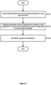
Figure 3 is a flow diagram of a first embodiment of a method of the present invention; -
Figure 4 is a schematic diagram of a second embodiment of a wireless telecommunications network of the present invention; -
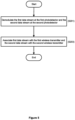
Figure 5 is a flow diagram of a second embodiment of a method of the present invention; and -
Figure 6 is a flow diagram of an embodiment of a method of the present invention. - A first embodiment of a
wireless telecommunications network 100 useful for understanding the present invention will now be described. As shown inFigure 2 , thewireless telecommunications network 100 includes a firstwireless transmitter 110a, a secondwireless transmitter 110b, and a Radio-Frequency (RF)receiver 120. In this embodiment, thefirst wireless transmitter 110a is configured to transmit wireless signals at a frequency of 2.8GHz and thesecond wireless transmitter 110b is configured to transmit wireless signals at a frequency of 5GHz. TheRF receiver 120 is a Rydberg-atom based RF receiver and includes avapour cell 121, aprobe laser 123, acoupling laser 125 and aphotodetector 127. TheRF receiver 120 also includes aprocessor 129 for processing the received signal data of thephotodetector 127. Thevapour cell 121 contains a vapour of alkali metal (in this embodiment, Rubidium-85). - The
RF receiver 120 may be configured so as to detect a wireless signal incident upon thevapour cell 120. This is achieved by configuring theprobe laser 123 of theRF receiver 120 to transmit a probe signal (illustrated by the solid arrowed line) through thevapour cell 121, thus exciting electrons of the Rubidium-85 atoms of thevapour cell 121, and by configuring thecoupling laser 125 of theRF receiver 120 to transmit a coupling signal (illustrated by the dashed arrowed line) through the vapour cell 121 (counter-propagating and overlapping the probe laser 123), thus also exciting electrons of the Rubidium-85 atoms in thevapour cell 121. The frequency of the probe signal is set to correlate with the transition of an electron of a Rubidium-85 atom from a ground state to a first excited state, and the frequency of the coupling signal is set to correlate with the transition of an electron of a Rubidium-85 atom from the first excited state to a predetermined Rydberg state. The predetermined Rydberg state is selected (based on the specific frequencies of the probe and coupling signals) so that a wireless signal incident upon thevapour cell 121 excites electrons from the predetermined Rydberg state to an adjacent Rydberg state, causing a detectable change in the Electromagnetically Induced Transparency (EIT) signal at thephotodetector 127. - In this embodiment, the
RF receiver 120 is configurable so as to detect wireless signals in a time-division multiplexing technique. This is achieved by theRF receiver 120 switching between a first configuration in which it is configured to detect a wireless signal of a first frequency in a first timeslot and a second configuration in which it is configured to detect a wireless signal of a second frequency in a second timeslot. In this example, the first configuration is for detecting wireless signals at a frequency of 2.8GHz and the second configuration is for detecting wireless signals at a frequency of 5GHz. Therefore, in the first configuration, the probe signal and coupling signals are selected so as to excite electrons to a first predetermined Rydberg state having the 90th principal quantum number energy state (i.e. the probe signal has a wavelength of 780nm and the coupling signal has a wavelength of 479.380nm). In this first configuration, wireless signals transmitted by thefirst wireless transmitter 110a at 2.8GHz that pass through thevapour cell 121 will excite electrons from this first predetermined Rydberg state to another Rydberg state, causing an EIT signal in the monitored probe signal at thephotodetector 127. Furthermore, in the second configuration, the probe signal and coupling signals are selected so as to excite electrons to a second predetermined Rydberg state having the 74th principal quantum number energy state (i.e. the probe signal has a wavelength of 780nm and the coupling signal has a wavelength of 479.537nm). In this second configuration, wireless signals transmitted by thesecond wireless transmitter 110b at 5GHz that pass through thevapour cell 121 will excite electrons from this second predetermined Rydberg state to another Rydberg state, causing an EIT signal in the monitored probe signal at thephotodetector 127. - The
RF receiver 120 also has acontroller 122 for controlling a frequency of the probe signal (i.e. to adjust and/or stabilise the frequency of the probe signal), for controlling a frequency of the coupling signal (i.e. to adjust and/or stabilise the frequency of the coupling signal), for controlling an intensity of the probe laser 123 (i.e. the transmission power and/or cross-sectional area of the probe laser 123), for controlling an intensity of the coupling laser 125 (i.e. the transmission power and/or cross-sectional area of the coupling laser 125), and for time synchronising thephotodetector 127 and at least one of theprobe laser 123 and coupling laser 125 (explained in more detail below). - In this embodiment, the
network 100 is configured for communication according to a time frame structure in which the time frame is divided into a plurality of timeslots, wherein a first subset of the plurality of timeslots are for communication of wireless signals at 2.8GHz and a second subset of the plurality of timeslots are for communication of wireless signals at 5GHz. Thefirst wireless transmitter 110a,second wireless transmitter 110b, andRF detector 120 are therefore time synchronised (or at least frame synchronised) so that the start of a time frame in each entity is at a common time. This synchronisation may be achieved by use of a Global Navigation Satellite System (GNSS) module, such as a Global Positioning System (GPS) module, or by an initial configuration process comprising sharing of synchronisation signals (as is common in cellular telecommunications protocols). - Furthermore, in this embodiment in which the
RF receiver 120 is configured to demultiplex a plurality of time-multiplexed data streams, then the first subset of the plurality of timeslots are designated for communication of a first data stream (between thefirst wireless transmitter 110a and RF receiver 120) and the second subset of the plurality of timeslots are designated for communication of a second data stream (between thesecond wireless transmitter 110b and RF receiver 120). - Accordingly, in each timeslot of the first subset of timeslots:
- the
first wireless transmitter 110a is configured to transmit its first data stream in wireless signals transmitted at 2.8GHz; -
controller 122 configures theprobe laser 123 and/orcoupling laser 125 so as to excite electrons to the first predetermined Rydberg state so thatRF detector 120 is configured to detect these wireless signals at 2.8GHz; and -
controller 122 configures theprocessor 129 so that the wireless signals received at thephotodetector 127 are demultiplexed into a first data stream. - Furthermore, for each timeslot of the second set of timeslots:
- the
second wireless transmitter 110b is configured to transmit the second data stream in wireless signals transmitted at 5GHz; -
controller 122 configures theprobe laser 123 and/orcoupling laser 125 so as to excite electrons to the second predetermined Rydberg state so thatRF detector 120 is configured to detect these wireless signals at 5GHz; and -
controller 122 configures theprocessor 129 so that the wireless signals received at thephotodetector 127 are demultiplexed into the second data stream. - The time frame structure used in the
network 100 may also utilise a guard interval, typically positioned at the beginning of a timeslot where the preceding timeslot is of another set, to enable thecontroller 122 to reconfigure theprobe laser 123,coupling laser 125 andprocessor 129. Furthermore, this reconfiguration must allow sufficient time for the electrons currently excited to one of the predetermined Rydberg states to decay and for electrons of the first excited state to be excited to the other predetermined Rydberg state. For example, when transitioning from a timeslot of the first set of timeslots (in which theRF detector 120 is configured such that electrons are excited to the first predetermined Rydberg state so as to detect 2.8GHz wireless signals) to a timeslot of the second set of timeslots (in which theRF detector 120 is configured such that electrons are excited to the second predetermined Rydberg state so as to detect 5GHz wireless signals), then the guard interval should allow sufficient time for electrons to decay from the first predetermined Rydberg state and for electrons to be excited to the second predetermined Rydberg state. This guard interval may be in the range of 3-5 microseconds. - A first embodiment of a method of the present invention will now be described with reference to
Figure 3 . This first embodiment of a method relates to the first embodiment of thewireless telecommunications network 100 described above and shown inFigure 2 . In this first embodiment, thefirst wireless transmitter 110a is transmitting wireless signals at 2.8GHz in a first set of timeslots of a time frame structure and thesecond wireless transmitter 110b transmits wireless signals at 5GHz in a second set of timeslots of the time frame structure. Wireless signals from both the first andsecond wireless transmitter vapour cell 121 of theRF detector 120. - In a first step (S101), the
controller 122 acquires a timing signature for communicating according to the time frame structure used by the first andsecond wireless transmitters controller 122 configures theprobe laser 123 and/orcoupling laser 125 to operate in the first configuration (described above, so as to detect wireless signals having a frequency of 2.8GHz) in each timeslot of the first set of timeslots, and in the second configuration (also described above, so as to detect wireless signals having a frequency of 5GHz) in each timeslot of the second set of timeslots. In step S105, thecontroller 122 configures theprocessor 129 to receive and demultiplex signals at the photodetector according to the time frame structure so that a first data stream is demultiplexed as data received during each timeslot of the first set of timeslots and a second data stream is demultiplexed as data received during each timeslot of the second set of timeslots. The first data stream is associated with thefirst wireless transmitter 110a and the second data stream is associated with thesecond wireless transmitter 110b. The first and second data streams may then be further processed (locally or by another entity). - This first embodiment of a method and
wireless telecommunications network 100 therefore provides a time-division multiplexing technique in communications from a wireless transmitter to an RF receiver that is based on a Rydberg-atom. This allows thephotodetector 129 to receive multiple multiplexed data streams in which each data stream is transmitted in a timeslot designated for that data stream. - Furthermore, in the first embodiment, the first data stream is transmitted at a first frequency in a first set of timeslots of a time frame structure and the second data stream is transmitted at a second frequency in a second set of timeslots of the time frame structure. However, this is non-essential as the first and second data streams may be transmitted at the same frequency, so long as they are time-multiplexed such that the first data stream is transmitted in the first set of timeslots and the second data stream is transmitted in the second set of timeslots. In other words, a data stream may be transmitted at the same frequency as all other data streams, the same frequency as a subset of the other data streams, or at a unique frequency (i.e. different to all other frequencies used by all other data streams). Each of these implementations enables a communication system in which an RF receiver having a Rydberg atom demultiplexes a multiplexed data stream.
- A second embodiment of a
wireless telecommunications network 200 will now be described with reference toFigure 4 . Thewireless telecommunications network 200 includes afirst wireless transmitter 210a, asecond wireless transmitter 210b, and a Radio-Frequency (RF)receiver 220. In this embodiment, thefirst wireless transmitter 210a is configured to transmit wireless signals at a frequency of 2.8GHz and thesecond wireless transmitter 210b is configured to transmit wireless signals at a frequency of 5GHz. TheRF receiver 220 is a Rydberg-atom based RF receiver and includes avapour cell 221, aprobe laser 223, abeam splitter 224, afirst coupling laser 225a, asecond coupling laser 225b, afirst photodetector 227a, asecond photodetector 227b, a firstdichroic mirror 228a and a seconddichroic mirror 228b. TheRF receiver 220 also includes aprocessor 229 for processing the received signals of the first andsecond photodetectors vapour cell 221 contains a vapour of alkali metal (in this embodiment, Rubidium-85). Thebeam splitter 224 splits a probe signal transmitted by theprobe laser 223 into a first path and a second path, discussed below. - The
RF receiver 220 also has acontroller 222 for controlling a frequency of the probe signal (i.e. to adjust and/or stabilise the frequency of the probe signal), for controlling a frequency of the first coupling signal (i.e. to adjust and/or stabilise the frequency of the first coupling signal), for controlling a frequency of the second coupling signal (i.e. to adjust and/or stabilise the frequency of the second coupling signal), for controlling an intensity of the probe laser 223 (i.e. the transmission power and/or cross-sectional area of the probe laser 223), and for controlling an intensity of the first andsecond coupling lasers second coupling lasers - The
RF receiver 220 is configured so as to detect a wireless signal incident upon thevapour cell 221. This is achieved by configuring theprobe laser 223 of theRF receiver 220 to transmit a probe signal (illustrated by the solid arrowed lines) in a first path through thevapour cell 221 to excite electrons of the Rubidium-85 atoms of the first path of thevapour cell 221, by configuring theprobe laser 223 of theRF receiver 220 to transmit a probe signal in a second path to excite electrons of the Rubidium-85 atoms of the second path of thevapour cell 221, by configuring thefirst coupling laser 225a of theRF receiver 220 to transmit a first coupling signal (illustrated by a dashed arrowed line) along the first path of vapour cell 221 (counter-propagating and overlapping the first path of the probe signal) to excite electrons of the Rubidium-85 atoms of the first path of thevapour cell 221, and by configuring thesecond coupling laser 225b of theRF receiver 220 to transmit a second coupling signal (illustrated by a dashed single dotted arrowed line) along the second path of vapour cell 221 (counter-propagating and overlapping the second path of the probe signal) to excite electrons of the Rubidium-85 atoms of the second path of thevapour cell 221. The first path of the probe signal is directed towards thefirst photodetector 227a by the firstdichroic mirror 228a and the second path of the probe signal is directed towards thesecond photodetector 227b by the seconddichroic mirror 228b. The frequency of the probe signal is set to correlate with the transition of an electron of a Rubidium-85 atom from a ground state to a first excited state, the frequency of the first coupling signal is set to correlate with the transition of an electron of a Rubidium-85 atom from the first excited state to a first predetermined Rydberg state, and the frequency of the second coupling signal is set to correlate with the transition of an electron of a Rubidium-85 atom from the first excited state to a second predetermined Rydberg state. The first predetermined Rydberg state is selected (based on the specific frequencies of the probe and first coupling signals) so that a wireless signal of a first frequency incident upon thevapour cell 221 excites electrons from the first predetermined Rydberg state to another Rydberg state, causing a detectable change in the EIT signal at thefirst photodetector 227a. Furthermore, the second predetermined Rydberg state is selected (based on the specific frequencies of the probe and second coupling signals) so that a wireless signal of a second frequency incident upon thevapour cell 221 excites electrons from the second predetermined Rydberg state to another Rydberg state, causing a detectable change in the EIT signal at thesecond photodetector 227b. TheRF receiver 220 of this second embodiment is therefore configured for spatial division multiplexing so as to detect wireless signals of a first frequency at thefirst photodetector 227a and detect wireless signals of the second frequency at thesecond photodetector 227b. - In this example, the
controller 222 configures theprobe laser 223 and/orfirst coupling laser 225a so that the first path detects wireless signals at a frequency of 2.8GHz and further configures theprobe laser 223 and/orsecond coupling laser 225b so that the second path detects wireless signals at a frequency of 5GHz. Thus, in this example, the probe signal and first coupling signal are selected so as to excite electrons to a first predetermined Rydberg state having the 90th principal quantum number energy state (i.e. the probe signal has a wavelength of 780nm and the coupling signal has a wavelength of 479.380nm) such that wireless signals transmitted by thefirst wireless transmitter 210a at 2.8GHz that pass through the first path of thevapour cell 221 will excite electrons from the first predetermined Rydberg state to an adjacent Rydberg state, causing an EIT signal in the monitored probe signal at thefirst photodetector 227a. Furthermore, in this example, the probe signal and second coupling signal are selected so as to excite electrons to a second predetermined Rydberg state having the 74th principal quantum number energy state (i.e. the probe signal has a wavelength of 780nm and the coupling signal has a wavelength of 479.537nm) such that wireless signals transmitted by thesecond wireless transmitter 210b at 5GHz that pass through the second path of thevapour cell 221 will excite electrons from the second predetermined Rydberg state to an adjacent Rydberg state, causing an EIT signal in the monitored probe signal at thesecond photodetector 227b. - A second embodiment of a method of the present invention will now be described with reference to
Figure 5 . This second embodiment of a method relates to the second embodiment of the wireless telecommunications network 300 described above and shown inFigure 4 . In this second embodiment, thefirst wireless transmitter 210a is transmitting wireless signals at 2.8GHz and thesecond wireless transmitter 210b transmits wireless signals at 5GHz. Wireless signals from both the first andsecond wireless transmitter vapour cell 221 of theRF detector 220. - In a first step (S201) of this second embodiment, the
processor 229 receives signals at thefirst photodetector 227a and demodulates these signals into a first data stream. These signals received at thefirst photodetector 227a are those transmitted by thefirst wireless transmitter 210a at 2.8GHz and incident upon the first path of thevapour cell 221 of theRF detector 220. Furthermore, in step S201, theprocessor 229 receives signals at thesecond photodetector 227b and demodulates these signals into a second data stream. These signals received at thesecond photodetector 227b are those transmitted by thesecond wireless transmitter 210b at 5GHz and incident upon the second path of thevapour cell 221 of theRF detector 220. In step 203, the first data stream is associated with thefirst wireless transmitter 210a and the second data stream is associated with thesecond wireless transmitter 210b. The first and second data streams may then be further processed (locally or by another entity). - This second embodiment therefore provides an RF detector having a plurality of paths that are contemporaneously detect wireless signals. In other words, the RF detector of this second embodiment is configured for spatial division multiplexing such that a first wireless signal may be detected at the
first photodetector 227a whilst a second wireless signal is be simultaneously detected at thesecond photodetector 227b. The network 300 of this second embodiment therefore enables multi-carrier communications in which multiple frequencies are communicated at the same time. Thenetwork 200 of this second embodiment therefore also has an increased capacity compared to RF receivers of the prior art which, at any one time, have a single path configured to receive wireless signals of a single frequency. This additional capacity may be used to increase multiplexing (i.e. such that a greater number of data streams may be communicated) or to increase the data rate for a particular data stream (i.e. such that more timeslots may be designated for the particular data stream). - In the above second embodiment, communications between the
first wireless transmitter 210a,second wireless transmitter 210b andRF receiver 220 are configured for communication of a plurality of spatially-multiplexed data streams. This may be enhanced by further multiplexing in the time-domain to enable communication of a plurality of time-and-space multiplexed data streams. For example, thefirst wireless transmitter 210a andRF receiver 220 may be further configured for time-division multiplexing by communicating according to a first time frame structure in which a first data stream is communicated during a first subset of timeslots of the first time frame structure and a second data stream is communicated during a second subset of timeslots of the first time frame structure. TheRF receiver 220 may therefore be configured so that theprocessor 229 receives and demultiplexes signals at thefirst photodetector 227a according to the first time frame structure so that a first data stream is demultiplexed as data received during each timeslot of the first set of timeslots of the first time frame structure and a second data stream is demultiplexed as data received during each timeslot of the second set of timeslots of the first time frame structure. Furthermore, thesecond wireless transmitter 210b andRF receiver 220 may be further configured for time-division multiplexing by communicating according to a second time frame structure in which a third data stream is communicated during a first subset of timeslots of the second time frame structure and a fourth data stream is communicated during a second subset of timeslots of the second time frame structure. TheRF receiver 220 may therefore be configured so that theprocessor 229 receives and demultiplexes signals at thesecond photodetector 227b according to the second time frame structure so that the third data stream is demultiplexed as data received during each timeslot of the first set of timeslots of the second time frame structure and the fourth data stream is demultiplexed as data received during each timeslot of the second set of timeslots of the second time frame structure. This configuration increases the amount of multiplexing achievable in the network 300. - In a further modification of the above second embodiment, the network 300 may be configured for time-and-space multiplexed communications but using a single frequency. That is, each data stream is communicated at the same frequency. Furthermore, the first and second paths of the
vapour cell 221 of theRF detector 220 may be configured to detect that same frequency. In this implementation, the first path of theRF detector 220 is configured to detect a wireless signal during a first subset of timeslots and is not configured to detect a wireless signal during a second subset of timeslots, and the second path of theRF detector 220 is configured to detect a wireless signal during the second subset of timeslots and is not configured to detect a wireless signal during the first subset of timeslots. This may be achieved by directing the coupling signal to the first path only during the first subset of timeslots and directing the coupling signal to the second path only during the second subset of timeslots. In this configuration, each path transitions from a first condition in which there is no excitation by a coupling signal to a second condition in which there is excitation by a coupling signal at the start of its respective subset of timeslots (i.e. the first subset of timeslots for the first path and second subset of timeslots for the second path). By controlling the intensity of the coupling signal such that Ωc 2 is less than Γ1Γ2 (in which Ωc is a Rabi frequency of the coupling signal, Γ1 is the decay rate of the first excited state of the transmission medium, and Γ2 is the decay rate of the predetermined excited state of the transmission medium), and by controlling the detector such that the time difference between the coupling signal being directed along a particular path and subsequently being directed along that same path again is greater than the time for electrons of the Rubidium-85 atoms contained in that path to return to their state under the first condition (e.g. the ground state or a first excited state, depending on the presence of the probe signal during the first condition), then the time for the EIT signal to respond to a change in presence of a wireless signal at the RF receiver is reduced (relative to the scenario in which each path is constantly excited by the coupling signal), such that higher data rate communications are achievable. This advantage is explained in more detail in Applicant's corresponding UK patent application number2105096.8 - In the above second embodiment, a single probe laser produces a probe signal that follows a first and second path (by being split by the beam splitter). This is non-essential and a first and second probe laser may be used instead (for example, where the first path and second path require probe signals at different frequencies). Furthermore, it is non-essential that distinct lasers are used to produce a distinct frequency. That is, a single laser may produce a plurality of laser signals, each at a particular frequency, by using a frequency comb. Furthermore, where a laser is used for each laser signal, only a first signal needs to be tuned and stabilised (using e.g. modulation transfer spectroscopy) at the frequency required for a first laser signal and each other laser may use a laser frequency offset locking technique to produce its respective laser signal. The laser frequency offset locking technique produces a second laser signal by splitting off a portion of the first laser signal and combining this portion with a lower frequency beat signal (that is relatively easy to produce and stabilise). The frequency of the beat signal is equal to the difference between the frequencies of the first laser signal and the second laser signal.
- The skilled person will understand that it is non-essential that the atomic medium of the RF detector that may be excited to the predetermined Rydberg states is contained in a vapour cell. That is, the atomic medium may be part of a hollow-core fibre segment of an optical fibre. For example, a hollow core fibre implementation of the first embodiment above may include counter-propagating probe and coupling lasers along an optical fibre with a hollow core segment, and further including a circulator to direct the probe laser towards a photodetector. In another example, a hollow core fibre implementation of the second embodiment above may include counter propagating probe and coupling lasers that are respectively split into a plurality of optical fibre cores (the probe and/or coupling signal of each optical fibre core may be different so as to detect wireless signals of different frequencies, which may be achieved, for example, using a frequency comb) wherein the probe signal of each optical fibre core is directed towards a photodetector using a circulator. The plurality of optical fibre cores may be a plurality of optical fibres each having a single core or may be a plurality of cores of a single fibre. The plurality of optical fibre cores may comprise, for example, 64 cores.
- Furthermore, it is non-essential that the atomic medium is comprised of Rubidium-85 atoms. Instead, the atomic medium may be comprised of any other alkali metal, such as Caesium or Strontium.
- The skilled person will also understand that the above methods may be applied to many other electromagnetic signals of different frequencies. That is, for a particular target frequency, a system may be configured such that an EIT signal is produced on a probe signal by an incident electromagnetic signal at that target frequency (such as by selecting an appropriate atomic medium (e.g. Rubidium, Caesium or Strontium) having Rydberg states that correspond with that target frequency). Furthermore, it is also non-essential that the EIT signal is produced following a ladder configuration of electron transitions. That is, any configuration (e.g. Lambda, Vee) may be used.
-
Figure 6 is a flow diagram illustrating an embodiment of the present invention. In step S301, a first electromagnetic field is detected at the transmission medium. In step S303, the detected first electromagnetic field is associated with a first data steam of a plurality of data streams. In step S305, a second electromagnetic field is detected at the transmission medium. In step S307, the detected second electromagnetic field is associated with a second data steam of the plurality of data streams. Embodiments of the present invention therefore provide various forms of multiplexing (e.g. time, space and/or frequency) in order to increase the number of data streams that may be simultaneously received at the detector. - The skilled reader will also understand that it is non-essential for the processor to be part of the same device as the remainder of the RF detector. That is, a signal from the/each photodetector may be transmitted to a remote processor for processing into a plurality of data streams.
- The skilled person will understand that any combination of features is possible within the scope of the invention, as claimed.
Claims (15)
- A method of receiving a plurality of data streams at an electromagnetic field receiver (220) in a wireless telecommunications network (200), wherein the electromagnetic field receiver (220) comprises a first optical transmitter (223), a second optical transmitter (225a, 225b), a first transmission medium (221), a second transmission medium (221), a first photodetector (227a) and a second photodetector (227b), the first and second transmission media (221) being spatially distinct, wherein the first optical transmitter (223) is configured to transmit a first probe signal to the first photodetector (227a) through the first transmission medium (221) at a first probe frequency and further configured to transmit a second probe signal to the second photodetector through the second transmission medium (221) at a second probe frequency, and the second optical transmitter (225a, 225b) is configured to transmit a first coupling signal through the first transmission medium (221) at a first coupling frequency and further configured to transmit a second coupling signal through the second transmission medium (221) at a second coupling frequency, wherein the first probe frequency and first coupling frequency are set to excite electrons of the first transmission medium (221) to a first predetermined Rydberg state so as to induce an Electromagnetic Induced Transparency, EIT, effect in the first transmission medium (221) such that an incident electromagnetic field at a first frequency at the first transmission medium (221) causes a detectable change in the first probe signal at the first photodetector (227a), wherein the second probe frequency and second coupling frequency are set to excite electrons of the second transmission medium (221) to a second predetermined Rydberg state so as to induce an EIT effect in the second transmission medium (221) such that an electromagnetic field at a second frequency incident at the second transmission medium (221) causes a detectable change in the second probe signal at the second photodetector (227b), wherein the plurality of data streams are time multiplexed in a first time frame comprising a plurality of timeslots, such that a first data stream is communicated in a first subset of the plurality of timeslots of the first time frame and a second data stream is communicated in a second subset of the plurality of timeslots of the first time frame, the method comprising the steps of:obtaining data indicating detection by the first photodetector (227a), in the first probe signal, of a first electromagnetic field incident at the first transmission medium (221) during a timeslot of the first subset of the plurality of timeslots;associating the detected first electromagnetic field with a first data stream of the plurality of data streams;obtaining data indicating detection by the second photodetector (227b), in the second probe signal, of a second electromagnetic field incident at the second transmission medium (221) during a timeslot of the second subset of the plurality of timeslots; andassociating the detected second electromagnetic field with a second data stream of the plurality of data streams.
- A method as claimed in Claim 1, wherein the first predetermined Rydberg state and second predetermined Rydberg state are the same.
- A method as claimed in Claim 2, wherein the first probe signal and first coupling signal are transmitted through the first and second transmission media (221) in a first condition and a second condition, in which:in the first condition of each transmission medium (221), the probe and coupling signals are transmitted through that transmission medium (221),the second condition of each transmission medium (221) exists for a time period for which an effect of the coupling signal on the electrons of the transmission medium (221) persists after a switch from the first condition to the second condition, and,an intensity of the coupling signal is such that:

- A method as claimed in Claim 1, wherein the first predetermined Rydberg state and second predetermined Rydberg state are different.
- A method as claimed in Claim 4, wherein the plurality of data streams are also time multiplexed in second time frame comprising a plurality of timeslots, such that a third data stream is communicated in a first subset of the plurality of timeslots of the second time frame and a fourth data stream is communicated in a second subset of the plurality of timeslots of the second time frame, and the method further comprises the steps of:obtaining data indicating detection of a third electromagnetic field incident at the transmission medium (221) during a timeslot of the first subset of the plurality of timeslots of the second time frame;associating the detected third electromagnetic field with the third data stream of the plurality of data streams;obtaining data indicating detection of a fourth electromagnetic field incident at the transmission medium (221) during a timeslot of the second subset of the plurality of timeslots of the second time frame; andassociating the detected fourth electromagnetic field with the fourth data stream of the plurality of data streams.
- A method of receiving a plurality of data streams at an electromagnetic field receiver (220) in a wireless telecommunications network (200), wherein the electromagnetic field receiver (220) comprises a first optical transmitter (223), a second optical transmitter (225a, 225b), a first transmission medium (221), a second transmission medium (221), a first photodetector (227a) and a second photodetector (227b), the first and second transmission media (221) being spatially distinct, wherein the first optical transmitter (223) is configured to transmit a first probe signal to the first photodetector (227a) through the first transmission medium (221) at a first probe frequency and is further configured to transmit a second probe signal to the second photodetector (227b) through the second transmission medium (221) at a second probe frequency, the second optical transmitter (225a, 225b) is configured to transmit a first coupling signal through the first transmission medium (221) at a first coupling frequency and is further configured to transmit a second coupling signal through the second transmission medium (221) at a second coupling frequency, the first probe frequency and first coupling frequency are set to excite electrons of the first transmission medium (221) to a first predetermined Rydberg state so as to induce an Electromagnetically Inducted Transparency, EIT, effect in the first transmission medium (221) such that an electromagnetic field at a first frequency incident at the first transmission medium (221) causes a detectable change in the first probe signal at the first photodetector (227a), and the second probe frequency and second coupling frequency are set to excite electrons of the second transmission medium (221) to a second predetermined Rydberg state, different to the first predetermined Rydberg state, so as to induce an EIT effect in the second transmission medium (221) such that an electromagnetic field at a second frequency incident at the second transmission medium (221) causes a detectable change in the second probe signal at the second photodetector (227b), the method comprising the steps of:obtaining data indicating detection by the first photodetector (227a), in the first probe signal, of a first electromagnetic field incident at the first transmission medium (221);associating the detected first electromagnetic field with a first data stream of the plurality of data streams;obtaining data indicating detection by the second photodetector (227b), in the second probe signal, of a second electromagnetic field incident at the second transmission medium (221); andassociating the detected second electromagnetic field with a second data stream of the plurality of data streams.
- A computer program comprising instructions which, when the program is executed by a processor, cause the processor to carry out the steps of any one of Claims 1 to 6.
- A computer readable carrier medium comprising the computer program of Claim 7.
- A device for processing a plurality of data streams received at an electromagnetic field receiver (220) in a wireless telecommunications network (200), the electromagnetic field receiver (220) including a first transmission medium (221), a second transmission medium (221) being spatially distinct to the first transmission medium (221), a first photodetector (227a), a second photodetector (227b), a first optical transmitter (223) configured to transmit a first probe signal to the first photodetector (227a) through the first transmission medium (221) at a first probe frequency and to transmit a second probe signal to the second photodetector (227b) through the second transmission medium (221) at a second probe frequency, and a second optical transmitter (225a, 225b) configured to transmit a first coupling signal through the first transmission medium (221) at a first coupling frequency and to transmit a second coupling signal through the second transmission medium (221) at a second coupling frequency, wherein the first probe frequency and first coupling frequency are set to excite electrons of the first transmission medium (221) to a first predetermined Rydberg state so as to induce an Electromagnetic Induced Transparency, EIT, effect in the first transmission medium (221) such that an incident electromagnetic field at a first frequency at the first transmission medium (221) causes a detectable change in the first probe signal at the first photodetector (227a), wherein the second probe frequency and second coupling frequency are set to excite electrons of the second transmission medium (221) to a second predetermined Rydberg state so as to induce an EIT effect in the second transmission medium (221) such that an electromagnetic field at a second frequency incident at the second transmission medium (221) causes a detectable change in the second probe signal at the second photodetector (227b), wherein the plurality of data streams are time multiplexed in a first time frame comprising a plurality of timeslots, such that the first data stream is communicated in a first subset of the plurality of timeslots of the first time frame and the second data stream is communicated in a second subset of the plurality of timeslots of the first time frame, the device comprising a processor configured to:obtain data indicating detection by the first photodetector (227a), in the first probe signal, of a first electromagnetic field incident at the first transmission medium (221) during a timeslot of the first subset of the plurality of timeslots,associate the detected first electromagnetic field with a first data stream of the plurality of data streams,obtain data indicating detection by the second photodetector (227b), in the second probe signal, of a second electromagnetic field incident at the second transmission medium (221) during a timeslot of the second subset of the plurality of timeslots, andassociate the detected second electromagnetic field with a second data stream of the plurality of data streams.
- A device as claimed in Claim 9, wherein the first predetermined Rydberg state and second predetermined Rydberg state are the same.
- A device as claimed in Claim 10, wherein the first probe signal and first coupling signal are transmitted through the first and second transmission media (221) in a first condition and a second condition, in which:in the first condition of each transmission medium (221), the probe and coupling signals are transmitted within that transmission medium (221),the second condition of each transmission medium (221) exists for a time period for which an effect of the coupling signal on the electrons of the transmission medium (221) persists after a switch from the first condition to the second condition, and,an intensity of the coupling signal is such that:
 in which Ωc is a Rabi frequency of the coupling signal, Γ1 is the transition rate out of the first excited state of the transmission medium (221), and Γ2 is the transition rate out of the predetermined excited state of the transmission medium (221).
 - A device as claimed in Claim 9, wherein the first predetermined Rydberg state and second predetermined Rydberg state are different.
- A device as claimed in Claim 12, wherein the plurality of data streams are also time multiplexed in second time frame comprising a plurality of timeslots, such that a third data stream is communicated in a first subset of the plurality of timeslots of the second time frame and a fourth data stream is communicated in a second subset of the plurality of timeslots of the second time frame, and detection of a third electromagnetic field incident at the transmission medium (221) is during a timeslot of the first subset of the plurality of timeslots of the second time frame and detection of a fourth electromagnetic field incident at the transmission medium (221) is during a timeslot of the second subset of the plurality of timeslots of the second time frame, and the processor is further configured to:associate the detected third electromagnetic field with the third data stream of the plurality of data streams; andassociate the detected fourth electromagnetic field with the fourth data stream of the plurality of data streams.
- A device for processing a plurality of data streams received at an electromagnetic field receiver (220) in a wireless telecommunications network (200), the electromagnetic field receiver (220) including a first transmission medium (221), a second transmission medium (221) being spatially distinct to the first transmission medium (221), a first photodetector (227a), a second photodetector (227b), a first optical transmitter (223) configured to transmit a first probe signal to the first photodetector (227a) through the first transmission medium (221) at a first probe frequency and further configured to transmit a second probe signal to the second photodetector (227b) through the second transmission medium (221) at a second probe frequency, and a second optical transmitter (225a, 225b) configured to transmit a first coupling signal through the first transmission medium (221) at a first coupling frequency and further configured to transmit a second coupling signal through the second transmission medium (221) at a second coupling frequency, wherein the first probe frequency and first coupling frequency are set to excite electrons of the first transmission medium (221) to a first predetermined Rydberg state so as to induce an Electromagnetically Inducted Transparency, EIT, effect in the first transmission medium (221) such that an electromagnetic field at a first frequency incident at the first transmission medium (221) causes a detectable change in the first probe signal at the first photodetector (227a), and the second probe frequency and second coupling frequency are set to excite electrons of the second transmission medium (221) to a second predetermined Rydberg state, different to the first predetermined excited state, so as to induce an EIT effect in the second transmission medium (221) such that an electromagnetic field at a second frequency incident at the second transmission medium (221) causes a detectable change in the second probe signal at the second photodetector (227b), the device comprising a processor configured to:obtain data indicating detection by the first photodetector (227a), in the first probe signal, of a first electromagnetic field incident at the first transmission medium (221),associate the detected first electromagnetic field with a first data stream of the plurality of data streams,obtain data indicating detection by the second photodetector (227b), in the second probe signal, of a second electromagnetic field incident at the second transmission medium (221), andassociate the detected second electromagnetic field with a second data stream of the plurality of data streams.
- A device as claimed in any one of Claims 9 to 14, being part of the electromagnetic field receiver (220).
Applications Claiming Priority (2)
| Application Number | Priority Date | Filing Date | Title |
|---|---|---|---|
| GB2105101.6A GB2605651A (en) | 2021-04-09 | 2021-04-09 | Electromagnetic field receiver |
| PCT/EP2022/055578 WO2022214251A1 (en) | 2021-04-09 | 2022-03-04 | Electromagnetic field receiver |
Publications (2)
| Publication Number | Publication Date |
|---|---|
| EP4320452A1 EP4320452A1 (en) | 2024-02-14 |
| EP4320452B1 true EP4320452B1 (en) | 2024-11-27 |
Family
ID=75949514
Family Applications (1)
| Application Number | Title | Priority Date | Filing Date |
|---|---|---|---|
| EP22712911.1A Active EP4320452B1 (en) | 2021-04-09 | 2022-03-04 | Electromagnetic field receiver |
Country Status (5)
| Country | Link |
|---|---|
| US (1) | US12250025B2 (en) |
| EP (1) | EP4320452B1 (en) |
| CN (1) | CN117157539B (en) |
| GB (1) | GB2605651A (en) |
| WO (1) | WO2022214251A1 (en) |
Families Citing this family (5)
| Publication number | Priority date | Publication date | Assignee | Title |
|---|---|---|---|---|
| GB2605650B (en) | 2021-04-09 | 2023-06-07 | British Telecomm | Electromagnetic field detector |
| US20240304433A1 (en) * | 2023-03-10 | 2024-09-12 | The Regents Of The University Of Michigan | Feedback Control Of High-Vaccum Cold-Ion Sources Using Rydberg Atom Spectroscopy |
| WO2025021380A1 (en) * | 2023-07-25 | 2025-01-30 | British Telecommunications Public Limited Company | Rydberg-atom based electromagnetic field receiver |
| WO2025228630A1 (en) * | 2024-05-03 | 2025-11-06 | British Telecommunications Public Limited Company | A telecommunications network comprising a rydberg-atom based em signal receiver |
| EP4718752A1 (en) * | 2024-09-26 | 2026-04-01 | British Telecommunications public limited company | Method and system for wireless telecommunications |
Family Cites Families (15)
| Publication number | Priority date | Publication date | Assignee | Title |
|---|---|---|---|---|
| US8054073B2 (en) | 2008-05-21 | 2011-11-08 | Entanglement Technologies, Llc | Method and apparatus for implementing EIT magnetometry |
| CN103616568B (en) | 2013-12-07 | 2016-01-20 | 山西大学 | Based on microwave induced method and the device of Rydberg atom |
| EP3308146B1 (en) | 2015-06-15 | 2020-02-26 | The Regents of The University of Michigan | Atom-based electromagnetic radiation electric-field sensor |
| CN105068025B (en) | 2015-07-16 | 2017-08-11 | 山西大学 | Method and device based on electromagnetic induced transparency effect measurement Weak magentic-field field strength |
| GB201522640D0 (en) | 2015-12-22 | 2016-02-03 | Isis Innovation | Electromagnetic frequency converter |
| CN106802373B (en) * | 2016-12-02 | 2019-07-12 | 北京无线电测量研究所 | A kind of atomic sensor system and electric field intensity measuremenrt method measuring electric field strength |
| CN110401492B (en) * | 2018-07-27 | 2020-08-21 | 中国计量科学研究院 | A quantum effect-based radio AM signal receiving method and AM quantum receiver |
| CN109001137B (en) | 2018-09-21 | 2021-01-05 | 山东科技大学 | Broadband light absorption method using microwave-assisted rydberg atoms |
| US11349569B2 (en) * | 2018-10-26 | 2022-05-31 | Raytheon Company | Methods and apparatus for implementing an optical transceiver using a vapor cell |
| US10979147B2 (en) * | 2019-03-11 | 2021-04-13 | Government Of The United States Of America, As Represented By The Secretary Of Commerce | Rydberg atom mixer and determining phase of modulated carrier radiation |
| US10763966B1 (en) * | 2019-03-25 | 2020-09-01 | Otago Innovation Limited | Data communications system using an optical antenna |
| CN114424111B (en) * | 2019-10-24 | 2022-12-27 | 英国电讯有限公司 | Apparatus and system for propagating a signal, and electromagnetic field detector and method of operating the same |
| GB2597260B (en) * | 2020-07-16 | 2022-12-07 | British Telecomm | Electromagnetic field receiver |
| CN112415284B (en) * | 2020-11-04 | 2022-03-04 | 中国人民解放军国防科技大学 | Portable microwave electric field measurement device based on Rydberg atoms |
| GB2605650B (en) | 2021-04-09 | 2023-06-07 | British Telecomm | Electromagnetic field detector |
-
2021
- 2021-04-09 GB GB2105101.6A patent/GB2605651A/en not_active Withdrawn
-
2022
- 2022-03-04 CN CN202280027185.8A patent/CN117157539B/en active Active
- 2022-03-04 EP EP22712911.1A patent/EP4320452B1/en active Active
- 2022-03-04 US US18/554,529 patent/US12250025B2/en active Active
- 2022-03-04 WO PCT/EP2022/055578 patent/WO2022214251A1/en not_active Ceased
Also Published As
| Publication number | Publication date |
|---|---|
| US12250025B2 (en) | 2025-03-11 |
| US20240089008A1 (en) | 2024-03-14 |
| EP4320452A1 (en) | 2024-02-14 |
| GB2605651A (en) | 2022-10-12 |
| CN117157539A (en) | 2023-12-01 |
| GB202105101D0 (en) | 2021-05-26 |
| WO2022214251A1 (en) | 2022-10-13 |
| CN117157539B (en) | 2024-10-25 |
Similar Documents
| Publication | Publication Date | Title |
|---|---|---|
| US12250025B2 (en) | Electromagnetic field receiver | |
| EP3930229B1 (en) | Wideband rf spectrum real-time monitor | |
| EP4005116B1 (en) | Wireless telecommunications network | |
| US8265488B2 (en) | Electromagnetic transmission/reception system | |
| US9689968B2 (en) | Wholly optically controlled phased array radar transmitter | |
| EP4331143A1 (en) | Wireless transceiver | |
| US12438250B2 (en) | Methods and systems for providing quantum computer interface | |
| EP3370353B1 (en) | Communications system providing photonic conversion and power detection and related methods | |
| CN116261833B (en) | Telecommunication network | |
| CN110190889A (en) | A kind of implementation method of the earth station system based on Microwave photonics | |
| EP4320451B1 (en) | Electromagnetic field detector | |
| EP0418546B1 (en) | Optical mixer | |
| EP4701103A1 (en) | Quantum radio frequency (rf) signal transmitter having a plurality of rydberg cells and rf signal combiner and associated methods | |
| US12613264B2 (en) | Rydberg sensor having an optical fiber path feeding Rydberg sensing regions and associated methods | |
| Glance | An optical heterodyne mixer providing image-frequency rejection | |
| CN114785419B (en) | Signal receiving device and signal receiving method | |
| EP4701102A1 (en) | Quantum radio frequency (rf) signal transmitter having a rydberg cell and associated methods | |
| Wilson et al. | Phased array antenna beamforming using a micromachined silicon spatial light modulator | |
| WO2025061378A1 (en) | A device for a wireless telecommunications network, a system comprising the device, and a method of operating the device | |
| Karapetyan | Microwave gyroscope—novel rotation sensor | |
| JPWO2019017145A1 (en) | Optical microwave transmission device, frequency conversion device, and phase control device | |
| JPH10126345A (en) | Method and device for generating and transmitting optical millimeter wave |
Legal Events
| Date | Code | Title | Description |
|---|---|---|---|
| STAA | Information on the status of an ep patent application or granted ep patent |
Free format text: STATUS: UNKNOWN |
|
| STAA | Information on the status of an ep patent application or granted ep patent |
Free format text: STATUS: THE INTERNATIONAL PUBLICATION HAS BEEN MADE |
|
| PUAI | Public reference made under article 153(3) epc to a published international application that has entered the european phase |
Free format text: ORIGINAL CODE: 0009012 |
|
| STAA | Information on the status of an ep patent application or granted ep patent |
Free format text: STATUS: REQUEST FOR EXAMINATION WAS MADE |
|
| 17P | Request for examination filed |
Effective date: 20230919 |
|
| AK | Designated contracting states |
Kind code of ref document: A1 Designated state(s): AL AT BE BG CH CY CZ DE DK EE ES FI FR GB GR HR HU IE IS IT LI LT LU LV MC MK MT NL NO PL PT RO RS SE SI SK SM TR |
|
| P01 | Opt-out of the competence of the unified patent court (upc) registered |
Effective date: 20240227 |
|
| GRAP | Despatch of communication of intention to grant a patent |
Free format text: ORIGINAL CODE: EPIDOSNIGR1 |
|
| STAA | Information on the status of an ep patent application or granted ep patent |
Free format text: STATUS: GRANT OF PATENT IS INTENDED |
|
| DAV | Request for validation of the european patent (deleted) | ||
| DAX | Request for extension of the european patent (deleted) | ||
| RIC1 | Information provided on ipc code assigned before grant |
Ipc: H04B 10/67 20130101ALI20240607BHEP Ipc: G01R 29/08 20060101AFI20240607BHEP |
|
| INTG | Intention to grant announced |
Effective date: 20240626 |
|
| GRAS | Grant fee paid |
Free format text: ORIGINAL CODE: EPIDOSNIGR3 |
|
| GRAA | (expected) grant |
Free format text: ORIGINAL CODE: 0009210 |
|
| STAA | Information on the status of an ep patent application or granted ep patent |
Free format text: STATUS: THE PATENT HAS BEEN GRANTED |
|
| AK | Designated contracting states |
Kind code of ref document: B1 Designated state(s): AL AT BE BG CH CY CZ DE DK EE ES FI FR GB GR HR HU IE IS IT LI LT LU LV MC MK MT NL NO PL PT RO RS SE SI SK SM TR |
|
| REG | Reference to a national code |
Ref country code: GB Ref legal event code: FG4D |
|
| REG | Reference to a national code |
Ref country code: CH Ref legal event code: EP |
|
| REG | Reference to a national code |
Ref country code: DE Ref legal event code: R096 Ref document number: 602022008202 Country of ref document: DE |
|
| REG | Reference to a national code |
Ref country code: IE Ref legal event code: FG4D |
|
| REG | Reference to a national code |
Ref country code: LT Ref legal event code: MG9D |
|
| REG | Reference to a national code |
Ref country code: NL Ref legal event code: MP Effective date: 20241127 |
|
| PG25 | Lapsed in a contracting state [announced via postgrant information from national office to epo] |
Ref country code: HR Free format text: LAPSE BECAUSE OF FAILURE TO SUBMIT A TRANSLATION OF THE DESCRIPTION OR TO PAY THE FEE WITHIN THE PRESCRIBED TIME-LIMIT Effective date: 20241127 Ref country code: IS Free format text: LAPSE BECAUSE OF FAILURE TO SUBMIT A TRANSLATION OF THE DESCRIPTION OR TO PAY THE FEE WITHIN THE PRESCRIBED TIME-LIMIT Effective date: 20250327 Ref country code: PT Free format text: LAPSE BECAUSE OF FAILURE TO SUBMIT A TRANSLATION OF THE DESCRIPTION OR TO PAY THE FEE WITHIN THE PRESCRIBED TIME-LIMIT Effective date: 20250327 |
|
| PG25 | Lapsed in a contracting state [announced via postgrant information from national office to epo] |
Ref country code: FI Free format text: LAPSE BECAUSE OF FAILURE TO SUBMIT A TRANSLATION OF THE DESCRIPTION OR TO PAY THE FEE WITHIN THE PRESCRIBED TIME-LIMIT Effective date: 20241127 Ref country code: NL Free format text: LAPSE BECAUSE OF FAILURE TO SUBMIT A TRANSLATION OF THE DESCRIPTION OR TO PAY THE FEE WITHIN THE PRESCRIBED TIME-LIMIT Effective date: 20241127 |
|
| REG | Reference to a national code |
Ref country code: AT Ref legal event code: MK05 Ref document number: 1746155 Country of ref document: AT Kind code of ref document: T Effective date: 20241127 |
|
| PG25 | Lapsed in a contracting state [announced via postgrant information from national office to epo] |
Ref country code: BG Free format text: LAPSE BECAUSE OF FAILURE TO SUBMIT A TRANSLATION OF THE DESCRIPTION OR TO PAY THE FEE WITHIN THE PRESCRIBED TIME-LIMIT Effective date: 20241127 |
|
| PG25 | Lapsed in a contracting state [announced via postgrant information from national office to epo] |
Ref country code: ES Free format text: LAPSE BECAUSE OF FAILURE TO SUBMIT A TRANSLATION OF THE DESCRIPTION OR TO PAY THE FEE WITHIN THE PRESCRIBED TIME-LIMIT Effective date: 20241127 |
|
| PG25 | Lapsed in a contracting state [announced via postgrant information from national office to epo] |
Ref country code: NO Free format text: LAPSE BECAUSE OF FAILURE TO SUBMIT A TRANSLATION OF THE DESCRIPTION OR TO PAY THE FEE WITHIN THE PRESCRIBED TIME-LIMIT Effective date: 20250227 |
|
| PG25 | Lapsed in a contracting state [announced via postgrant information from national office to epo] |
Ref country code: AT Free format text: LAPSE BECAUSE OF FAILURE TO SUBMIT A TRANSLATION OF THE DESCRIPTION OR TO PAY THE FEE WITHIN THE PRESCRIBED TIME-LIMIT Effective date: 20241127 Ref country code: GR Free format text: LAPSE BECAUSE OF FAILURE TO SUBMIT A TRANSLATION OF THE DESCRIPTION OR TO PAY THE FEE WITHIN THE PRESCRIBED TIME-LIMIT Effective date: 20250228 Ref country code: LV Free format text: LAPSE BECAUSE OF FAILURE TO SUBMIT A TRANSLATION OF THE DESCRIPTION OR TO PAY THE FEE WITHIN THE PRESCRIBED TIME-LIMIT Effective date: 20241127 |
|
| PG25 | Lapsed in a contracting state [announced via postgrant information from national office to epo] |
Ref country code: PL Free format text: LAPSE BECAUSE OF FAILURE TO SUBMIT A TRANSLATION OF THE DESCRIPTION OR TO PAY THE FEE WITHIN THE PRESCRIBED TIME-LIMIT Effective date: 20241127 |
|
| PG25 | Lapsed in a contracting state [announced via postgrant information from national office to epo] |
Ref country code: RS Free format text: LAPSE BECAUSE OF FAILURE TO SUBMIT A TRANSLATION OF THE DESCRIPTION OR TO PAY THE FEE WITHIN THE PRESCRIBED TIME-LIMIT Effective date: 20250227 |
|
| PG25 | Lapsed in a contracting state [announced via postgrant information from national office to epo] |
Ref country code: SM Free format text: LAPSE BECAUSE OF FAILURE TO SUBMIT A TRANSLATION OF THE DESCRIPTION OR TO PAY THE FEE WITHIN THE PRESCRIBED TIME-LIMIT Effective date: 20241127 |
|
| PG25 | Lapsed in a contracting state [announced via postgrant information from national office to epo] |
Ref country code: DK Free format text: LAPSE BECAUSE OF FAILURE TO SUBMIT A TRANSLATION OF THE DESCRIPTION OR TO PAY THE FEE WITHIN THE PRESCRIBED TIME-LIMIT Effective date: 20241127 |
|
| PG25 | Lapsed in a contracting state [announced via postgrant information from national office to epo] |
Ref country code: EE Free format text: LAPSE BECAUSE OF FAILURE TO SUBMIT A TRANSLATION OF THE DESCRIPTION OR TO PAY THE FEE WITHIN THE PRESCRIBED TIME-LIMIT Effective date: 20241127 |
|
| PG25 | Lapsed in a contracting state [announced via postgrant information from national office to epo] |
Ref country code: RO Free format text: LAPSE BECAUSE OF FAILURE TO SUBMIT A TRANSLATION OF THE DESCRIPTION OR TO PAY THE FEE WITHIN THE PRESCRIBED TIME-LIMIT Effective date: 20241127 |
|
| PG25 | Lapsed in a contracting state [announced via postgrant information from national office to epo] |
Ref country code: SK Free format text: LAPSE BECAUSE OF FAILURE TO SUBMIT A TRANSLATION OF THE DESCRIPTION OR TO PAY THE FEE WITHIN THE PRESCRIBED TIME-LIMIT Effective date: 20241127 |
|
| PG25 | Lapsed in a contracting state [announced via postgrant information from national office to epo] |
Ref country code: CZ Free format text: LAPSE BECAUSE OF FAILURE TO SUBMIT A TRANSLATION OF THE DESCRIPTION OR TO PAY THE FEE WITHIN THE PRESCRIBED TIME-LIMIT Effective date: 20241127 |
|
| PG25 | Lapsed in a contracting state [announced via postgrant information from national office to epo] |
Ref country code: IT Free format text: LAPSE BECAUSE OF FAILURE TO SUBMIT A TRANSLATION OF THE DESCRIPTION OR TO PAY THE FEE WITHIN THE PRESCRIBED TIME-LIMIT Effective date: 20241127 |
|
| REG | Reference to a national code |
Ref country code: DE Ref legal event code: R097 Ref document number: 602022008202 Country of ref document: DE |
|
| PG25 | Lapsed in a contracting state [announced via postgrant information from national office to epo] |
Ref country code: SE Free format text: LAPSE BECAUSE OF FAILURE TO SUBMIT A TRANSLATION OF THE DESCRIPTION OR TO PAY THE FEE WITHIN THE PRESCRIBED TIME-LIMIT Effective date: 20241127 |
|
| PLBE | No opposition filed within time limit |
Free format text: ORIGINAL CODE: 0009261 |
|
| STAA | Information on the status of an ep patent application or granted ep patent |
Free format text: STATUS: NO OPPOSITION FILED WITHIN TIME LIMIT |
|
| REG | Reference to a national code |
Ref country code: CH Ref legal event code: L10 Free format text: ST27 STATUS EVENT CODE: U-0-0-L10-L00 (AS PROVIDED BY THE NATIONAL OFFICE) Effective date: 20251008 |
|
| PG25 | Lapsed in a contracting state [announced via postgrant information from national office to epo] |
Ref country code: MC Free format text: LAPSE BECAUSE OF FAILURE TO SUBMIT A TRANSLATION OF THE DESCRIPTION OR TO PAY THE FEE WITHIN THE PRESCRIBED TIME-LIMIT Effective date: 20241127 |
|
| REG | Reference to a national code |
Ref country code: CH Ref legal event code: H13 Free format text: ST27 STATUS EVENT CODE: U-0-0-H10-H13 (AS PROVIDED BY THE NATIONAL OFFICE) Effective date: 20251023 |
|
| 26N | No opposition filed |
Effective date: 20250828 |
|
| PG25 | Lapsed in a contracting state [announced via postgrant information from national office to epo] |
Ref country code: LU Free format text: LAPSE BECAUSE OF NON-PAYMENT OF DUE FEES Effective date: 20250304 |
|
| REG | Reference to a national code |
Ref country code: BE Ref legal event code: MM Effective date: 20250331 |
|
| PG25 | Lapsed in a contracting state [announced via postgrant information from national office to epo] |
Ref country code: BE Free format text: LAPSE BECAUSE OF NON-PAYMENT OF DUE FEES Effective date: 20250331 |
|
| PG25 | Lapsed in a contracting state [announced via postgrant information from national office to epo] |
Ref country code: CH Free format text: LAPSE BECAUSE OF NON-PAYMENT OF DUE FEES Effective date: 20250331 |
|
| PG25 | Lapsed in a contracting state [announced via postgrant information from national office to epo] |
Ref country code: IE Free format text: LAPSE BECAUSE OF NON-PAYMENT OF DUE FEES Effective date: 20250304 |
|
| PGFP | Annual fee paid to national office [announced via postgrant information from national office to epo] |
Ref country code: GB Payment date: 20260220 Year of fee payment: 5 |
|
| PGFP | Annual fee paid to national office [announced via postgrant information from national office to epo] |
Ref country code: DE Payment date: 20260219 Year of fee payment: 5 |
|
| PGFP | Annual fee paid to national office [announced via postgrant information from national office to epo] |
Ref country code: FR Payment date: 20260219 Year of fee payment: 5 |