EP0418546B1 - Optical mixer - Google Patents
Optical mixer Download PDFInfo
- Publication number
- EP0418546B1 EP0418546B1 EP90115480A EP90115480A EP0418546B1 EP 0418546 B1 EP0418546 B1 EP 0418546B1 EP 90115480 A EP90115480 A EP 90115480A EP 90115480 A EP90115480 A EP 90115480A EP 0418546 B1 EP0418546 B1 EP 0418546B1
- Authority
- EP
- European Patent Office
- Prior art keywords
- optical
- gain
- amplifier
- modulated
- intensity
- Prior art date
- Legal status (The legal status is an assumption and is not a legal conclusion. Google has not performed a legal analysis and makes no representation as to the accuracy of the status listed.)
- Expired - Lifetime
Links
Images

Classifications
-
- G—PHYSICS
- G02—OPTICS
- G02F—OPTICAL DEVICES OR ARRANGEMENTS FOR THE CONTROL OF LIGHT BY MODIFICATION OF THE OPTICAL PROPERTIES OF THE MEDIA OF THE ELEMENTS INVOLVED THEREIN; NON-LINEAR OPTICS; FREQUENCY-CHANGING OF LIGHT; OPTICAL LOGIC ELEMENTS; OPTICAL ANALOGUE/DIGITAL CONVERTERS
- G02F2/00—Demodulating light; Transferring the modulation of modulated light; Frequency-changing of light
- G02F2/002—Demodulating light; Transferring the modulation of modulated light; Frequency-changing of light using optical mixing
-
- H—ELECTRICITY
- H01—ELECTRIC ELEMENTS
- H01S—DEVICES USING THE PROCESS OF LIGHT AMPLIFICATION BY STIMULATED EMISSION OF RADIATION [LASER] TO AMPLIFY OR GENERATE LIGHT; DEVICES USING STIMULATED EMISSION OF ELECTROMAGNETIC RADIATION IN WAVE RANGES OTHER THAN OPTICAL
- H01S5/00—Semiconductor lasers
- H01S5/06—Arrangements for controlling the laser output parameters, e.g. by operating on the active medium
- H01S5/0607—Arrangements for controlling the laser output parameters, e.g. by operating on the active medium by varying physical parameters other than the potential of the electrodes, e.g. by an electric or magnetic field, mechanical deformation, pressure, light, temperature
- H01S5/0608—Arrangements for controlling the laser output parameters, e.g. by operating on the active medium by varying physical parameters other than the potential of the electrodes, e.g. by an electric or magnetic field, mechanical deformation, pressure, light, temperature controlled by light, e.g. optical switch
- H01S5/0609—Arrangements for controlling the laser output parameters, e.g. by operating on the active medium by varying physical parameters other than the potential of the electrodes, e.g. by an electric or magnetic field, mechanical deformation, pressure, light, temperature controlled by light, e.g. optical switch acting on an absorbing region, e.g. wavelength convertors
-
- H—ELECTRICITY
- H04—ELECTRIC COMMUNICATION TECHNIQUE
- H04B—TRANSMISSION
- H04B10/00—Transmission systems employing electromagnetic waves other than radio-waves, e.g. infrared, visible or ultraviolet light, or employing corpuscular radiation, e.g. quantum communication
- H04B10/60—Receivers
Landscapes
- Physics & Mathematics (AREA)
- General Physics & Mathematics (AREA)
- Electromagnetism (AREA)
- Optics & Photonics (AREA)
- Condensed Matter Physics & Semiconductors (AREA)
- Nonlinear Science (AREA)
- Engineering & Computer Science (AREA)
- Computer Networks & Wireless Communication (AREA)
- Signal Processing (AREA)
- Optical Communication System (AREA)
Description
- The present invention relates to an optical mixer for up/down-converting an intensity-modulated optical signal.
- Subcarrier multiplexing (SCM) of an optical carrier has been proposed as an alternative to time division multiplexing in multiple access lightwave systems (T E Darcie. Subcarrier Multiplexing for Multiple Access lightwave Networks. J> Lightwave Technology, 1987, LT-5, pp.1103-1110). In a SCM scheme an optical carrier is intensity modulated by one or more subcarriers at microwave frequencies, each of which provides an information channel.
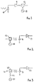
- A typical receiver configuration for a SCM system is shown in Figure 1 of the accompanying drawings. A photodetector 10 (typically a pin diode) detects all the subcarrier channels, but only the required channel need be demodulated. The receiver sensitivity is determined by the detector electronic bandwidth and the bandwidth of individual channels. A microwave preamplifier 11 amplifies the subcarrier channel of interest prior to downconversion in a
mixer 12 fed by alocal oscillator 13. Unfortunately the noise figure of available preamplifiers 11 increases as the operating frequency increases, and the receiver sensitivity decreases correspondingly. - An alternative detection technique has been proposed (T E Darcie et al. Optical Mixer Preamplifier for Lightwave Subcarrier Systems. Electronic Letters, 1988, Vol.24, pp. 179-180), in which the subcarrier signals are downconverted optically by an
optical mixer 15, before photodetection (see Figure 2 of the accompanying drawings). The downconverted optical signals are then detected using alow speed photodetector 16 andpreamplifier 17. In this prior proposal, the optical mixer is constituted by a semiconductoroptical amplifier 15 the gain of which is modulated by applying modulated electrical bias current to theamplifier 15 from alocal oscillator 18. An incoming intensity modulated (IM) optical signal propagating through the amplifier interacts with the modulated gain to produce frequency shifted components of the intensity modulation. The optical mixer thus depends on the fact that the gain of the semiconductor optical amplifier used is dependent on the bias current applied. However, a drawback of this prior arrangement is that the maximum frequency at which gain modulation can be achieved is limited by the carrier lifetime of the semiconductoroptical amplifier 15 as is illustrated by line A of the gain-modulation/modulation-frequency graph shown in Figure 4 of the accompanying drawings. - According to the present invention, there is provided an optical mixer for up/down-converting a sub-carrier signal, of a first frequency, that is intensity-modulated onto a first optical signal, said optical mixer comprising an optical amplifier and gain-modulating means for modulating the gain of the optical amplifier, characterised in that said gain-modulating means comprises means for generating a second optical signal intensity-modulated at a second frequency and launching the second optical signal into the optical amplifier at an intensity to cause the amplifier to operate at least partially within its saturated gain region whereby to cause the gain of said amplifier to be modulated at said second frequency resulting in up/down conversion of said sub-carrier signal.
- The present invention thus relies on the gain saturation properties of optical amplifiers (including, but not limited to, semiconductor optical amplifiers) to produce gain modulation. The optical mixer of the invention can be used in many applications where up/down-conversion of intensity-modulated optical signals is required.
- An optical mixer embodying the invention will now be described, by way of non-limiting example, with reference to the accompanying diagrammatic drawings, in which:
- Figure 1
- is a diagram of a first, known, receiver for SCM optical signals in which signal downconversion is carried out after optical detection;
- Figure 2
- is a diagram of a second, also known, receiver for SCM optical signals in which an incoming optical signal is optically downconverted prior to detection by means of an electrically-modulated optical amplifier;
- Figure 3
- is a diagram of a third receiver for SCM optical signals in which an incoming optical signal is optically downconverted prior to detection by means of an optical mixer embodying the invention;
- Figure 4
- is a graph showing the drop off in gain modulation with frequency for the optical mixers of the second and third receiver; and
- Figure 5
- is a graph showing the gain/output power characteristic of a typical optical amplifier.
- The prior art SCM receivers illustrated in Figures 1 and 2 have already been explained in the introductory portion of this specification and will therefore not be described again.
- The receiver illustrated in Figure 3 comprises an
optical mixer 20, 23 arranged to optically downconvert an incoming SCM optical signal prior to detection by aphotodetector 21 and amplification by pre-amplifier 22. The optical mixer is constituted by anoptical amplifier 20 the gain of which is modulated by the technique described below. - Optical amplifiers exhibit gain saturation as the output optical intensity increases beyond a certain level (see, for example, K Inoue et al, "Gain Saturation Dependance on Signal Wavelength in a Travelling Wave Semiconductor Laser Amplifier", Electronics Letters, 1987, Vol. 23, pp.328-329; and also M J O'Mahonay, "Semiconductor Laser Optical Amplifiers for Use in Future Fiber Systems", J Lightwave Technology, Vol. 6, 1988, pp. 531-544). Figure 5 illustrates this gain saturation phenomenum. The "saturation intensity" is defined as the output intensity at which the gain is 3 dB less than the unsaturated gain. Thus an unsaturated gain region may be defined for output intensities less than the saturation intensity, and a saturated gain region may be defined for output intensities greater than the saturation intensity.
- The gain of such an optical amplifier may be modulated by an optical signal that is intensity modulated such that the amplifier operates either wholly or partly within the saturated gain region. Any intensity modulated optical signals in the unsaturated gain region will then mix with the modulated gain to produce frequency shifted output components of the intensity modulation.
- For example, if the gain of an optical amplifier were modulated such that

where 'G(t)' is the gain at time t, 'G' is the gain with zero modulation, 'a' is a constant, and 'w1' is the modulation frequency,
and an incoming intensity-modulated optical signal of the form:
where 'Pi(t)' is signal power at time t, 'P' is the mean signal power, 'b' is a constant, and 'w2' is the frequency of intensity modulation
then the output signal would be:
where 'Po(t)' is the output power at time t - The frequency spectrum of the intensity modulation of the output optical signal would then consist of components at w1, w2, (w1 + w2) and (w1 - w2).
- The gain-modulation drop off with frequency of such optically-modulated optical amplifiers is less severe than is the case with bias-current modulated amplifiers, as is illustrated by line B of Figure 4.
- Returning now to a consideration of Figure 3, the
optical amplifier 20 is constituted by a resonant near travelling wave or travelling wave optical amplifier with suitable gain saturation characteristics. A steady state pumping mechanism (nuclear, chemical, electrical or optical) is applied to the optical amplifier to establish a suitable steady state gain (e.g. in the case of a semiconductor optical amplifier this would be a dc electrical bias current). An intensity-modulated optical signal S2 is generated by any suitable means 23 (effectively acting as a local oscillator) and is launched into theamplifier 20 at a suitable intensity to achieve the desired gain modulation. The incoming signal S1 to be mixed is also launched into theamplifier 20. The frequency of intensity modulation of the local oscillator may be varied to tune the mixer. - Optical mixers of the form illustrated in Figure 3 may be used generally to downconvert (or upconvert) intensity modulated optical signals.
- Downconversion of intensity modulated signals at microwave frequencies prior to photodetection allows the use of lower speed photodetectors and electronic circuitry in optical receivers. Possible applications are wideband spectrum analysers and communication receivers.
- As an upconverter the mixer may be used to frequency shift subcarriers in a subcarrier multiplexed lightwave system.
- The optical gain-modulation of a semiconductor optical amplifier may be combined with electrical gain-modulation effected by modulation of the amplifier bias current; the optical and electrical modulations would, of course, be correlated with each other.
Claims (3)
- An optical mixer for up/down-converting a sub-carrier signal, of a first frequency, that is intensity-modulated onto a first optical signal (Sl), said optical mixer comprising an optical amplifier (20) and gain modulating means (23) for modulating the gain of the optical amplifier, characterised in that said gain-modulating means (23) comprises means for generating a second optical signal (S2) intensity-modulated at a second frequency and launching the said second optical signal into the optical amplifier (20) at an intensity to cause the amplifier to operate at least partially within its saturated gain region whereby to cause the gain of said amplifier to be modulated at said second frequency resulting in up/down conversion of said sub-carrier signal.
- An optical mixer according to claim 1, wherein the optical amplifier (20) is a semiconductor optical amplifier electrically biased by a d.c electrical bias current.
- An optical mixer according to claim 1, wherein the optical amplifier (20) is semiconductor optical amplifier electrically biased by an electrical bias current modulated in correspondence to modulating of said second optical signal (S2).
Applications Claiming Priority (2)
| Application Number | Priority Date | Filing Date | Title |
|---|---|---|---|
| GB898921244A GB8921244D0 (en) | 1989-09-20 | 1989-09-20 | Optical mixer |
| GB8921244 | 1989-09-20 |
Publications (3)
| Publication Number | Publication Date |
|---|---|
| EP0418546A2 EP0418546A2 (en) | 1991-03-27 |
| EP0418546A3 EP0418546A3 (en) | 1991-10-23 |
| EP0418546B1 true EP0418546B1 (en) | 1994-01-12 |
Family
ID=10663346
Family Applications (1)
| Application Number | Title | Priority Date | Filing Date |
|---|---|---|---|
| EP90115480A Expired - Lifetime EP0418546B1 (en) | 1989-09-20 | 1990-08-11 | Optical mixer |
Country Status (4)
| Country | Link |
|---|---|
| US (1) | US5111333A (en) |
| EP (1) | EP0418546B1 (en) |
| DE (1) | DE69005957T2 (en) |
| GB (1) | GB8921244D0 (en) |
Families Citing this family (11)
| Publication number | Priority date | Publication date | Assignee | Title |
|---|---|---|---|---|
| US5186146A (en) * | 1990-12-20 | 1993-02-16 | Hitachi, Ltd. | Combustion evaluation apparatus and combustion controller |
| US5264960A (en) * | 1992-05-08 | 1993-11-23 | At&T Bell Laboratories | Optical wavelength shifter |
| DE4324984A1 (en) * | 1993-07-26 | 1995-02-02 | Sel Alcatel Ag | Fiber optic amplifier as a wavelength converter |
| JP3534443B2 (en) * | 1994-07-06 | 2004-06-07 | 浜松ホトニクス株式会社 | Optical frequency mixing device |
| EP0717482A1 (en) * | 1994-12-14 | 1996-06-19 | AT&T Corp. | Semiconductor interferometric optical wavelength conversion device |
| JP3334025B2 (en) | 1995-11-13 | 2002-10-15 | ミノルタ株式会社 | Image forming device |
| US5961314A (en) * | 1997-05-06 | 1999-10-05 | Rosemount Aerospace Inc. | Apparatus for detecting flame conditions in combustion systems |
| WO2002061502A1 (en) * | 2001-01-30 | 2002-08-08 | Yoshinobu Maeda | Optical control method and device |
| US8469700B2 (en) | 2005-09-29 | 2013-06-25 | Rosemount Inc. | Fouling and corrosion detector for burner tips in fired equipment |
| KR101385108B1 (en) * | 2009-12-17 | 2014-04-29 | 한국전자통신연구원 | Photomixer module and terahertz wave generation method thereof |
| US9413456B2 (en) * | 2012-07-20 | 2016-08-09 | The Boeing Company | Non-linear optical receiver |
Family Cites Families (3)
| Publication number | Priority date | Publication date | Assignee | Title |
|---|---|---|---|---|
| US4364014A (en) * | 1978-03-30 | 1982-12-14 | Gray Richard W | Optical modulator |
| JPS553258A (en) * | 1978-06-21 | 1980-01-11 | Fujitsu Ltd | Optical communication system |
| US4794351A (en) * | 1986-09-29 | 1988-12-27 | American Telephone And Telegraph Company, At&T Bell Laboratories | Optical mixer for upconverting or downconverting an optical signal |
-
1989
- 1989-09-20 GB GB898921244A patent/GB8921244D0/en active Pending
-
1990
- 1990-08-11 DE DE90115480T patent/DE69005957T2/en not_active Expired - Fee Related
- 1990-08-11 EP EP90115480A patent/EP0418546B1/en not_active Expired - Lifetime
- 1990-09-19 US US07/585,685 patent/US5111333A/en not_active Expired - Fee Related
Also Published As
| Publication number | Publication date |
|---|---|
| DE69005957D1 (en) | 1994-02-24 |
| US5111333A (en) | 1992-05-05 |
| DE69005957T2 (en) | 1994-05-05 |
| GB8921244D0 (en) | 1989-11-08 |
| EP0418546A2 (en) | 1991-03-27 |
| EP0418546A3 (en) | 1991-10-23 |
Similar Documents
| Publication | Publication Date | Title |
|---|---|---|
| CA1306287C (en) | Transceiver for a bidirectional coherent optical transmission system | |
| US7149435B2 (en) | Method and apparatus for transmitting high-frequency signals in optical communication system | |
| US7483600B2 (en) | Integrated coherent optical detector | |
| US4742576A (en) | Optical communication system employing coherent detection and method | |
| Kuri et al. | Optical heterodyne detection technique for densely multiplexed millimeter-wave-band radio-on-fiber systems | |
| EP0910187B1 (en) | Coherent optical communication system | |
| US20080212974A1 (en) | Electromagnetic Transmission/Reception System | |
| EP0418546B1 (en) | Optical mixer | |
| EP0168914B1 (en) | Optical transmission system | |
| EP0263613B1 (en) | An optical mixer for upconverting or downconverting an optical signal | |
| JP4332616B2 (en) | Method and apparatus for signal processing of modulated light | |
| WO1993012591A1 (en) | Optical communications system and method for transmitting information through a single optical waveguide | |
| US6731922B1 (en) | Optical image reject down converter | |
| US6559986B1 (en) | Method for converting the signal modulation of channels of an optical multiplex system to subcarrier frequencies | |
| Ridgway et al. | Generation and modulation of a 94-GHz signal using electrooptic modulators | |
| US6452706B1 (en) | FM signal optical transmission apparatus and FM signal optical reception apparatus | |
| von Helmolt et al. | A mobile broad-band communication system based on mode-locked lasers | |
| Kojucharow et al. | Experimental investigation of WDM channel spacing in simultaneous upconversion millimeter-wave fiber transmission system at 60 GHz-band | |
| Polifko et al. | Fiber optic link architectural comparison for millimeter-wave transmission | |
| Bhattacharya et al. | Influence of adjacent channel interference on the frequency-modulated WDM optical communication system | |
| JPH04248721A (en) | Balanced optical receiver | |
| JPH0635563Y2 (en) | Optical information transmission network | |
| JPH06268591A (en) | Optical coherent communications equipment | |
| Watanabe et al. | Polarisation-insensitive 1.2 Gb/s optical DPSK heterodyne transmission experiment using polarisation diversity | |
| JPS60107626A (en) | Optical heterodyne-homodyne communication method |
Legal Events
| Date | Code | Title | Description |
|---|---|---|---|
| PUAI | Public reference made under article 153(3) epc to a published international application that has entered the european phase |
Free format text: ORIGINAL CODE: 0009012 |
|
| AK | Designated contracting states |
Kind code of ref document: A2 Designated state(s): DE FR GB |
|
| PUAL | Search report despatched |
Free format text: ORIGINAL CODE: 0009013 |
|
| AK | Designated contracting states |
Kind code of ref document: A3 Designated state(s): DE FR GB |
|
| 17P | Request for examination filed |
Effective date: 19920413 |
|
| 17Q | First examination report despatched |
Effective date: 19930504 |
|
| RAP1 | Party data changed (applicant data changed or rights of an application transferred) |
Owner name: HEWLETT-PACKARD COMPANY |
|
| GRAA | (expected) grant |
Free format text: ORIGINAL CODE: 0009210 |
|
| AK | Designated contracting states |
Kind code of ref document: B1 Designated state(s): DE FR GB |
|
| REF | Corresponds to: |
Ref document number: 69005957 Country of ref document: DE Date of ref document: 19940224 |
|
| ET | Fr: translation filed | ||
| PLBE | No opposition filed within time limit |
Free format text: ORIGINAL CODE: 0009261 |
|
| STAA | Information on the status of an ep patent application or granted ep patent |
Free format text: STATUS: NO OPPOSITION FILED WITHIN TIME LIMIT |
|
| 26N | No opposition filed | ||
| REG | Reference to a national code |
Ref country code: GB Ref legal event code: 732E |
|
| REG | Reference to a national code |
Ref country code: GB Ref legal event code: 732E |
|
| REG | Reference to a national code |
Ref country code: FR Ref legal event code: TP |
|
| REG | Reference to a national code |
Ref country code: FR Ref legal event code: TP |
|
| REG | Reference to a national code |
Ref country code: GB Ref legal event code: IF02 |
|
| PGFP | Annual fee paid to national office [announced via postgrant information from national office to epo] |
Ref country code: FR Payment date: 20020717 Year of fee payment: 13 |
|
| PGFP | Annual fee paid to national office [announced via postgrant information from national office to epo] |
Ref country code: GB Payment date: 20020807 Year of fee payment: 13 |
|
| PGFP | Annual fee paid to national office [announced via postgrant information from national office to epo] |
Ref country code: DE Payment date: 20020830 Year of fee payment: 13 |
|
| PG25 | Lapsed in a contracting state [announced via postgrant information from national office to epo] |
Ref country code: GB Free format text: LAPSE BECAUSE OF NON-PAYMENT OF DUE FEES Effective date: 20030811 |
|
| PG25 | Lapsed in a contracting state [announced via postgrant information from national office to epo] |
Ref country code: DE Free format text: LAPSE BECAUSE OF NON-PAYMENT OF DUE FEES Effective date: 20040302 |
|
| GBPC | Gb: european patent ceased through non-payment of renewal fee |
Effective date: 20030811 |
|
| PG25 | Lapsed in a contracting state [announced via postgrant information from national office to epo] |
Ref country code: FR Free format text: LAPSE BECAUSE OF NON-PAYMENT OF DUE FEES Effective date: 20040430 |
|
| REG | Reference to a national code |
Ref country code: FR Ref legal event code: ST |