EP4320002B1 - Electric drive vehicle - Google Patents
Electric drive vehicle Download PDFInfo
- Publication number
- EP4320002B1 EP4320002B1 EP22715201.4A EP22715201A EP4320002B1 EP 4320002 B1 EP4320002 B1 EP 4320002B1 EP 22715201 A EP22715201 A EP 22715201A EP 4320002 B1 EP4320002 B1 EP 4320002B1
- Authority
- EP
- European Patent Office
- Prior art keywords
- thermoregulation
- liquid
- vehicle
- circuit
- power storage
- Prior art date
- Legal status (The legal status is an assumption and is not a legal conclusion. Google has not performed a legal analysis and makes no representation as to the accuracy of the status listed.)
- Active
Links
Images



Classifications
-
- B—PERFORMING OPERATIONS; TRANSPORTING
- B60—VEHICLES IN GENERAL
- B60L—PROPULSION OF ELECTRICALLY-PROPELLED VEHICLES; SUPPLYING ELECTRIC POWER FOR AUXILIARY EQUIPMENT OF ELECTRICALLY-PROPELLED VEHICLES; ELECTRODYNAMIC BRAKE SYSTEMS FOR VEHICLES IN GENERAL; MAGNETIC SUSPENSION OR LEVITATION FOR VEHICLES; MONITORING OPERATING VARIABLES OF ELECTRICALLY-PROPELLED VEHICLES; ELECTRIC SAFETY DEVICES FOR ELECTRICALLY-PROPELLED VEHICLES
- B60L58/00—Methods or circuit arrangements for monitoring or controlling batteries or fuel cells, specially adapted for electric vehicles
- B60L58/10—Methods or circuit arrangements for monitoring or controlling batteries or fuel cells, specially adapted for electric vehicles for monitoring or controlling batteries
- B60L58/24—Methods or circuit arrangements for monitoring or controlling batteries or fuel cells, specially adapted for electric vehicles for monitoring or controlling batteries for controlling the temperature of batteries
- B60L58/26—Methods or circuit arrangements for monitoring or controlling batteries or fuel cells, specially adapted for electric vehicles for monitoring or controlling batteries for controlling the temperature of batteries by cooling
-
- B—PERFORMING OPERATIONS; TRANSPORTING
- B60—VEHICLES IN GENERAL
- B60K—ARRANGEMENT OR MOUNTING OF PROPULSION UNITS OR OF TRANSMISSIONS IN VEHICLES; ARRANGEMENT OR MOUNTING OF PLURAL DIVERSE PRIME-MOVERS IN VEHICLES; AUXILIARY DRIVES FOR VEHICLES; INSTRUMENTATION OR DASHBOARDS FOR VEHICLES; ARRANGEMENTS IN CONNECTION WITH COOLING, AIR INTAKE, GAS EXHAUST OR FUEL SUPPLY OF PROPULSION UNITS IN VEHICLES
- B60K1/00—Arrangement or mounting of electrical propulsion units
-
- B—PERFORMING OPERATIONS; TRANSPORTING
- B60—VEHICLES IN GENERAL
- B60K—ARRANGEMENT OR MOUNTING OF PROPULSION UNITS OR OF TRANSMISSIONS IN VEHICLES; ARRANGEMENT OR MOUNTING OF PLURAL DIVERSE PRIME-MOVERS IN VEHICLES; AUXILIARY DRIVES FOR VEHICLES; INSTRUMENTATION OR DASHBOARDS FOR VEHICLES; ARRANGEMENTS IN CONNECTION WITH COOLING, AIR INTAKE, GAS EXHAUST OR FUEL SUPPLY OF PROPULSION UNITS IN VEHICLES
- B60K1/00—Arrangement or mounting of electrical propulsion units
- B60K1/04—Arrangement or mounting of electrical propulsion units of the electric storage means for propulsion
-
- B—PERFORMING OPERATIONS; TRANSPORTING
- B60—VEHICLES IN GENERAL
- B60K—ARRANGEMENT OR MOUNTING OF PROPULSION UNITS OR OF TRANSMISSIONS IN VEHICLES; ARRANGEMENT OR MOUNTING OF PLURAL DIVERSE PRIME-MOVERS IN VEHICLES; AUXILIARY DRIVES FOR VEHICLES; INSTRUMENTATION OR DASHBOARDS FOR VEHICLES; ARRANGEMENTS IN CONNECTION WITH COOLING, AIR INTAKE, GAS EXHAUST OR FUEL SUPPLY OF PROPULSION UNITS IN VEHICLES
- B60K11/00—Arrangement in connection with cooling of propulsion units
- B60K11/02—Arrangement in connection with cooling of propulsion units with liquid cooling
-
- B—PERFORMING OPERATIONS; TRANSPORTING
- B60—VEHICLES IN GENERAL
- B60L—PROPULSION OF ELECTRICALLY-PROPELLED VEHICLES; SUPPLYING ELECTRIC POWER FOR AUXILIARY EQUIPMENT OF ELECTRICALLY-PROPELLED VEHICLES; ELECTRODYNAMIC BRAKE SYSTEMS FOR VEHICLES IN GENERAL; MAGNETIC SUSPENSION OR LEVITATION FOR VEHICLES; MONITORING OPERATING VARIABLES OF ELECTRICALLY-PROPELLED VEHICLES; ELECTRIC SAFETY DEVICES FOR ELECTRICALLY-PROPELLED VEHICLES
- B60L53/00—Methods of charging batteries, specially adapted for electric vehicles; Charging stations or on-board charging equipment therefor; Exchange of energy storage elements in electric vehicles
- B60L53/20—Methods of charging batteries, specially adapted for electric vehicles; Charging stations or on-board charging equipment therefor; Exchange of energy storage elements in electric vehicles characterised by converters located in the vehicle
-
- H—ELECTRICITY
- H01—ELECTRIC ELEMENTS
- H01M—PROCESSES OR MEANS, e.g. BATTERIES, FOR THE DIRECT CONVERSION OF CHEMICAL ENERGY INTO ELECTRICAL ENERGY
- H01M10/00—Secondary cells; Manufacture thereof
- H01M10/60—Heating or cooling; Temperature control
- H01M10/61—Types of temperature control
- H01M10/613—Cooling or keeping cold
-
- H—ELECTRICITY
- H01—ELECTRIC ELEMENTS
- H01M—PROCESSES OR MEANS, e.g. BATTERIES, FOR THE DIRECT CONVERSION OF CHEMICAL ENERGY INTO ELECTRICAL ENERGY
- H01M10/00—Secondary cells; Manufacture thereof
- H01M10/60—Heating or cooling; Temperature control
- H01M10/62—Heating or cooling; Temperature control specially adapted for specific applications
- H01M10/625—Vehicles
-
- H—ELECTRICITY
- H01—ELECTRIC ELEMENTS
- H01M—PROCESSES OR MEANS, e.g. BATTERIES, FOR THE DIRECT CONVERSION OF CHEMICAL ENERGY INTO ELECTRICAL ENERGY
- H01M10/00—Secondary cells; Manufacture thereof
- H01M10/60—Heating or cooling; Temperature control
- H01M10/65—Means for temperature control structurally associated with the cells
- H01M10/656—Means for temperature control structurally associated with the cells characterised by the type of heat-exchange fluid
- H01M10/6567—Liquids
- H01M10/6568—Liquids characterised by flow circuits, e.g. loops, located externally to the cells or cell casings
-
- B—PERFORMING OPERATIONS; TRANSPORTING
- B60—VEHICLES IN GENERAL
- B60K—ARRANGEMENT OR MOUNTING OF PROPULSION UNITS OR OF TRANSMISSIONS IN VEHICLES; ARRANGEMENT OR MOUNTING OF PLURAL DIVERSE PRIME-MOVERS IN VEHICLES; AUXILIARY DRIVES FOR VEHICLES; INSTRUMENTATION OR DASHBOARDS FOR VEHICLES; ARRANGEMENTS IN CONNECTION WITH COOLING, AIR INTAKE, GAS EXHAUST OR FUEL SUPPLY OF PROPULSION UNITS IN VEHICLES
- B60K1/00—Arrangement or mounting of electrical propulsion units
- B60K1/02—Arrangement or mounting of electrical propulsion units comprising more than one electric motor
-
- B—PERFORMING OPERATIONS; TRANSPORTING
- B60—VEHICLES IN GENERAL
- B60K—ARRANGEMENT OR MOUNTING OF PROPULSION UNITS OR OF TRANSMISSIONS IN VEHICLES; ARRANGEMENT OR MOUNTING OF PLURAL DIVERSE PRIME-MOVERS IN VEHICLES; AUXILIARY DRIVES FOR VEHICLES; INSTRUMENTATION OR DASHBOARDS FOR VEHICLES; ARRANGEMENTS IN CONNECTION WITH COOLING, AIR INTAKE, GAS EXHAUST OR FUEL SUPPLY OF PROPULSION UNITS IN VEHICLES
- B60K1/00—Arrangement or mounting of electrical propulsion units
- B60K2001/003—Arrangement or mounting of electrical propulsion units with means for cooling the electrical propulsion units
-
- B—PERFORMING OPERATIONS; TRANSPORTING
- B60—VEHICLES IN GENERAL
- B60K—ARRANGEMENT OR MOUNTING OF PROPULSION UNITS OR OF TRANSMISSIONS IN VEHICLES; ARRANGEMENT OR MOUNTING OF PLURAL DIVERSE PRIME-MOVERS IN VEHICLES; AUXILIARY DRIVES FOR VEHICLES; INSTRUMENTATION OR DASHBOARDS FOR VEHICLES; ARRANGEMENTS IN CONNECTION WITH COOLING, AIR INTAKE, GAS EXHAUST OR FUEL SUPPLY OF PROPULSION UNITS IN VEHICLES
- B60K1/00—Arrangement or mounting of electrical propulsion units
- B60K2001/003—Arrangement or mounting of electrical propulsion units with means for cooling the electrical propulsion units
- B60K2001/005—Arrangement or mounting of electrical propulsion units with means for cooling the electrical propulsion units the electric storage means
-
- B—PERFORMING OPERATIONS; TRANSPORTING
- B60—VEHICLES IN GENERAL
- B60K—ARRANGEMENT OR MOUNTING OF PROPULSION UNITS OR OF TRANSMISSIONS IN VEHICLES; ARRANGEMENT OR MOUNTING OF PLURAL DIVERSE PRIME-MOVERS IN VEHICLES; AUXILIARY DRIVES FOR VEHICLES; INSTRUMENTATION OR DASHBOARDS FOR VEHICLES; ARRANGEMENTS IN CONNECTION WITH COOLING, AIR INTAKE, GAS EXHAUST OR FUEL SUPPLY OF PROPULSION UNITS IN VEHICLES
- B60K1/00—Arrangement or mounting of electrical propulsion units
- B60K2001/008—Arrangement or mounting of electrical propulsion units with means for heating the electrical propulsion units
-
- B—PERFORMING OPERATIONS; TRANSPORTING
- B60—VEHICLES IN GENERAL
- B60K—ARRANGEMENT OR MOUNTING OF PROPULSION UNITS OR OF TRANSMISSIONS IN VEHICLES; ARRANGEMENT OR MOUNTING OF PLURAL DIVERSE PRIME-MOVERS IN VEHICLES; AUXILIARY DRIVES FOR VEHICLES; INSTRUMENTATION OR DASHBOARDS FOR VEHICLES; ARRANGEMENTS IN CONNECTION WITH COOLING, AIR INTAKE, GAS EXHAUST OR FUEL SUPPLY OF PROPULSION UNITS IN VEHICLES
- B60K1/00—Arrangement or mounting of electrical propulsion units
- B60K1/04—Arrangement or mounting of electrical propulsion units of the electric storage means for propulsion
- B60K2001/0405—Arrangement or mounting of electrical propulsion units of the electric storage means for propulsion characterised by their position
- B60K2001/0438—Arrangement under the floor
-
- B—PERFORMING OPERATIONS; TRANSPORTING
- B60—VEHICLES IN GENERAL
- B60K—ARRANGEMENT OR MOUNTING OF PROPULSION UNITS OR OF TRANSMISSIONS IN VEHICLES; ARRANGEMENT OR MOUNTING OF PLURAL DIVERSE PRIME-MOVERS IN VEHICLES; AUXILIARY DRIVES FOR VEHICLES; INSTRUMENTATION OR DASHBOARDS FOR VEHICLES; ARRANGEMENTS IN CONNECTION WITH COOLING, AIR INTAKE, GAS EXHAUST OR FUEL SUPPLY OF PROPULSION UNITS IN VEHICLES
- B60K7/00—Disposition of motor in, or adjacent to, traction wheel
- B60K2007/0092—Disposition of motor in, or adjacent to, traction wheel the motor axle being coaxial to the wheel axle
-
- B—PERFORMING OPERATIONS; TRANSPORTING
- B60—VEHICLES IN GENERAL
- B60L—PROPULSION OF ELECTRICALLY-PROPELLED VEHICLES; SUPPLYING ELECTRIC POWER FOR AUXILIARY EQUIPMENT OF ELECTRICALLY-PROPELLED VEHICLES; ELECTRODYNAMIC BRAKE SYSTEMS FOR VEHICLES IN GENERAL; MAGNETIC SUSPENSION OR LEVITATION FOR VEHICLES; MONITORING OPERATING VARIABLES OF ELECTRICALLY-PROPELLED VEHICLES; ELECTRIC SAFETY DEVICES FOR ELECTRICALLY-PROPELLED VEHICLES
- B60L2210/00—Converter types
- B60L2210/10—DC to DC converters
-
- H—ELECTRICITY
- H01—ELECTRIC ELEMENTS
- H01M—PROCESSES OR MEANS, e.g. BATTERIES, FOR THE DIRECT CONVERSION OF CHEMICAL ENERGY INTO ELECTRICAL ENERGY
- H01M10/00—Secondary cells; Manufacture thereof
- H01M10/60—Heating or cooling; Temperature control
- H01M10/63—Control systems
- H01M10/633—Control systems characterised by algorithms, flow charts, software details or the like
-
- Y—GENERAL TAGGING OF NEW TECHNOLOGICAL DEVELOPMENTS; GENERAL TAGGING OF CROSS-SECTIONAL TECHNOLOGIES SPANNING OVER SEVERAL SECTIONS OF THE IPC; TECHNICAL SUBJECTS COVERED BY FORMER USPC CROSS-REFERENCE ART COLLECTIONS [XRACs] AND DIGESTS
- Y02—TECHNOLOGIES OR APPLICATIONS FOR MITIGATION OR ADAPTATION AGAINST CLIMATE CHANGE
- Y02T—CLIMATE CHANGE MITIGATION TECHNOLOGIES RELATED TO TRANSPORTATION
- Y02T10/00—Road transport of goods or passengers
- Y02T10/60—Other road transportation technologies with climate change mitigation effect
- Y02T10/70—Energy storage systems for electromobility, e.g. batteries
Definitions
- This invention relates to an electric drive vehicle.
- a vehicle may only be provided with one or more electric motors (and, in this case, the drive is exclusively electric) or it may be provided with one or more electric motors in combination with a thermal engine (and, in this case, the drive may be exclusively electric, exclusively thermal, or hybrid).
- the electric motor (or each electric motor) is mechanically connected to the drive wheels and is electrically connected to a power storage system through the interposition of an electronic power converter.
- the power storage system consists of groups of electrochemical cells (generally with a "pouch” or prismatic structure) connected together in series (to increase the overall electric voltage); the electrochemical cell groups are generally connected to each other in parallel (to increase the intensity of the overall electric current).
- the power storage system may be very large and heavy (particularly if the drive is exclusively electric, in which case the power storage system may weigh more than 500 kg).
- the power storage system has a flat and (relatively) thin shape in order to be integrated inside of the chassis.
- the power storage system comprises a container having a lower wall (which constitutes the bottom of the vehicle facing the road surface) and housing the various groups of electrochemical cells inside, each of which forms a corresponding module.
- the power storage system In order to operate correctly and avoid rapid degradation, the power storage system needs to be maintained at a fairly consistent operating temperature and, thus, must be coupled with a thermoregulation system that is able to cool the power storage system when there is excessive heat (including when a still vehicle is recharging) and is able to heat the power storage system when it is too cold (typically after a cold start).
- the temperature interval within which the batteries optimally operate ranges between 10° and 30° (the lithium batteries in some use conditions may reach 45°, which is considered a limit operating temperature). Above this interval, there is the risk that some components will deteriorate and, with over-heating beyond 70°, the risk of fire for flammable elements, such as the acids and solvents composing the electrolytes, increases. In contrast, below this interval, the battery may be subject to gaps in efficiency that, below zero, are translated into a loss of as much as 40% autonomy.
- thermoregulation system of the power storage system is arranged in a front position (or, in front of the passenger compartment) since it is easier and more effective to arrange the radiators used by the thermoregulation system in the front position.
- the front part due to their bulk (for example, when the front part is particularly low and tapered for aerodynamic reasons), it is necessary to house in the front position (i.e., behind the passenger compartment) some components that need to be cooled in use, such as, for example, the on-board charger (OBC), the DC/DC converter to power the low-voltage utilities, and the hydraulic circuit used by the active suspensions.
- OBC on-board charger
- thermoregulation system of the power storage system in any case, this thermoregulation system is arranged in a front position and, thus, it is necessary to arrange relatively large pipes (so as not to have excessive pressure losses) that run from the front to the back, crossing the space of the passenger compartment with a noticeable increase in weight and bulkiness.
- thermoregulation circuit A vehicle with a power storage system and a thermoregulation circuit is known from US 2017/271727 A1 .
- the purpose of this invention is to provide an electric drive vehicle that is free of the drawbacks described above and is, at the same time, easy and economical to produce.
- an electric drive vehicle is provided, as claimed in independent claim 1.
- reference number 1 identifies, as a whole, a vehicle with electric drive provided with four drive wheels 2 (two front drive wheels 2 and two rear drive wheels 2).
- the vehicle 1 comprises an electric drivetrain system 3 that is arranged at the front position (i.e., it is connected to the two front drive wheels 2) and an electric drivetrain system 3 that is arranged at the rear position (i.e., it is connected to the two rear drive wheels 2), is structurally identical to the electric drivetrain system 3 in the front position, and is mechanically independent and separate from the electric drivetrain system 3 arranged at the front position.
- the vehicle 1 comprises a single electric drivetrain system 3 (arranged at the front position or arranged at the rear position) and, thus, only has two drive wheels 2; in this embodiment, the vehicle 1 could also comprise a thermal drivetrain system connected to the drive wheels 2 that do not receive the motion from the single electric drivetrain system 3.
- Each electric drivetrain system 3 comprises a pair of reversible electric machines 4 (i.e., that can function both as an electric motor absorbing electricity and generating mechanical torque, and as an electrical generator absorbing mechanical energy and generating electricity) provided with respective shafts and a pair of transmissions 5 connecting the electric machines 4 (i.e. the shafts of the electric machines 4) to the corresponding drive wheels 2 without the interposition of any clutch.
- a pair of reversible electric machines 4 i.e., that can function both as an electric motor absorbing electricity and generating mechanical torque, and as an electrical generator absorbing mechanical energy and generating electricity
- Each electric machine 4 is driven by a corresponding electronic AC/DC power converter (i.e., an inverter), which is connected to a power storage system 6 provided with chemical batteries; i.e., each electronic AC/DC power converter is bi-directional and comprises a side in direct current connected to the power storage system 6 and a side in alternating three-phase current that is connected to the corresponding electric machine 4.
- a corresponding electronic AC/DC power converter i.e., an inverter
- each electronic AC/DC power converter is bi-directional and comprises a side in direct current connected to the power storage system 6 and a side in alternating three-phase current that is connected to the corresponding electric machine 4.
- the power storage system 6 has a flat and (relatively) thin shape in order to be integrated inside of the vehicle 1 chassis.
- the power storage system 6 comprises a container 7 that internally houses multiple modules provided with respective electrochemical cells with a parallelepipedal shape (i.e., having a "pouch" structure, or a prismatic structure).
- the container 7 has a lower wall (which constitutes the bottom of the vehicle 1 facing the road surface and is, of course, oriented horizontally), an upper wall that is parallel and opposite to the lower wall, a front wall 8 facing a front part of the vehicle 1 (i.e. facing the front of the vehicle 1 in relation to the froward direction D), and has a rear wall 9 that is opposite the front wall 8 and faces a rear part of the vehicle 1 (i.e. facing the back of the vehicle 1 in relation to the forward direction D).
- the power storage system 6 is coupled to (integrated with) a main thermoregulation circuit 10 that is arranged inside the power storage system 6 (i.e., inside the container 7) and is configured to distribute a thermoregulation liquid (typically water-based) inside the power storage system 6 (i.e., inside the container 7).
- the main thermoregulation circuit 10 has an inlet 11 for the thermoregulation liquid (i.e. a point in which the thermoregulation liquid enters the main thermoregulation circuit 10) arranged through the front wall 8 of the power storage system 6 (i.e. of the container 7); in addition, the main thermoregulation circuit 10 has an outlet 12 for the thermoregulation liquid (i.e.
- thermoregulation liquid leaves the main thermoregulation circuit 10
- the thermoregulation liquid circulates through the main thermoregulation circuit 10 entering through the inlet 11 and leaving (in equal measure) through the outlet 12.
- the vehicle 1 comprises a thermoregulation system 13, which is arranged in a front position in front of the front wall 8 of the power storage system 6 (i.e., of the container 7) and is configured to cause the thermoregulation liquid to circulate in the main thermoregulation circuit 10 introducing the thermoregulation liquid into the inlet 11 and receiving (in equal measure) the thermoregulation liquid from the outlet 12.
- the thermoregulation system 13 cools the thermoregulation liquid (if the power storage system 6 needs to be cooled) i.e., it heats the thermoregulation liquid (if the power storage system 6 needs to be heated).
- the thermoregulation system 13 comprises a heat pump circuit 14 that is provided (among other things) with a compressor 15 and a heat exchanger 16 that exchanges heat with the thermoregulation liquid (i.e., it can both heat and cool the thermoregulation liquid).
- the heat pump circuit 14 could be replaced with an electric heater and a conventional cooling circuit.
- the thermoregulation system 13 preferably also comprises a radiator 17 that may be used (when the environmental conditions are right) to cool the thermoregulation liquid in combination with or alternately to the heat pump circuit 14.
- the vehicle 1 comprises a component 18 consisting of an on-board charger of the power storage system 6; i.e., the component 18 is used only when the vehicle 1 is parked, to recharge the power storage system 6, using an external power source connected via cable.
- the vehicle 1 comprises a component 19 consisting of a DC/DC converter powering the low-voltage utilities of the vehicle 1 itself; i.e., only when the vehicle 1 is in use, the DC/DC converter transfers a part of the power stored at high voltage (several hundred nominal volts) in the power storage system 6 into an additional low-voltage electrical circuit (typically 12 nominal volts and generally provided with its own backup battery) to which a series of low-voltage utilities of the vehicle 1 is connected.
- a component 19 consisting of a DC/DC converter powering the low-voltage utilities of the vehicle 1 itself; i.e., only when the vehicle 1 is in use, the DC/DC converter transfers a part of the power stored at high voltage (several hundred nominal volts) in the power storage system 6 into an additional low-voltage electrical circuit (typically 12 nominal volts and generally provided with its own backup battery) to which a series of low-voltage utilities of the vehicle 1 is connected.
- the vehicle 1 comprises a component 20 consisting of a hydraulic circuit used by an electronically controlled active suspension system; i.e., the active suspension system uses pressurised oil flowing in the hydraulic circuit to adjust the suspension response.
- the components 18, 19, and 20 are all arranged at the rear position behind the rear wall 9 of the power storage system 6 (i.e., of the container 7) and, thus, are arranged opposite the thermoregulation system 13 (which is located at the front).
- the vehicle 1 comprises a secondary thermoregulation circuit 21 that is arranged at the rear position behind the rear wall 9 of the power storage system 6 (i.e., of the container 7) and is coupled to three components 18, 19, and 20 to cool the components 18, 19, and 20 themselves (when necessary). It is important to highlight how the components 18, 19, and 20 must be cooled when their internal temperature is high, but they must never be heated since they do not have a minimum use temperature beyond which their performance deteriorates (considering the climates in which the vehicle 1 may reasonably be used).
- the main thermoregulation circuit 10 comprises a drawing point 22 that goes through the rear wall 9 of the power storage system 6 (i.e., of the container 7) and supplies the thermoregulation liquid to the secondary thermoregulation circuit 21; in addition, the main thermoregulation circuit 10 comprises a return point 23 that goes through the rear wall 9 of the power storage system 6 (i.e. of the container) and receives the thermoregulation liquid from the secondary thermoregulation circuit 21.
- the two points 22 and 23 are preferably arranged relatively close to each other along the main thermoregulation circuit 10; i.e., between the drawing point 22 and the return point 23 the main thermoregulation circuit 10 only has one (short) connection pipe that does not perform thermal exchange with any component inside the power storage system 6.
- the secondary thermoregulation circuit 21 uses the thermoregulation liquid that has been treated (i.e., cooled or heated) by the thermoregulation system 13 and drained (temporarily, i.e., "borrowed") from the main thermoregulation circuit 10 for its own operation.
- the secondary thermoregulation circuit 21 is entirely free of components designed to cool the thermoregulation liquid, since the secondary thermoregulation circuit 21 only has the function of circulating the thermoregulation liquid drained ("borrowed") from the main thermoregulation circuit 10 and treated (i.e., cooled or heated) by the thermoregulation system 13.
- the thermoregulation system 13 comprises a pump 24 (obviously arranged at the front position), which is configured to cause the thermoregulation liquid to circulate through the main thermoregulation circuit 10.
- the secondary thermoregulation circuit 21 comprises a pump 25 (obviously arranged at the rear position), which is configured to cause the thermoregulation liquid to circulate through the secondary thermoregulation circuit 21 by sucking the thermoregulation liquid from the drawing point 22. In fact, without adequate sucking from the pump 25, only a minimum, negligible portion of the thermoregulation liquid would naturally flow through the secondary thermoregulation circuit 21 from the drawing point 21 to the return point 22.
- the secondary thermoregulation circuit 21 has a bifurcation 26 in which the secondary thermoregulation circuit 21 is bifurcated into a branch 27 along which only the component 18 is arranged and a branch 28 along which the components 20 and 19 are arranged, one in series after the other.
- the two branches 27, 28 join one another downstream of the components 18, 19, 20 so as to flow together into the return point 23.
- the pump 25 is arranged upstream of the bifurcation 26, i.e., it is arranged between the drawing point 22 and the bifurcation 26.
- an electronically controlled stop valve 29 is arranged that is designed to open or close the passage through the branch 27; similarly, along the branch 28, an electronically controlled stop valve 30 is arranged that is designed to open or close the passage through the branch 28.
- the component 20 i.e., the hydraulic circuit used by the electronically controlled active suspension system
- the component 20 comprises a heat exchanger 31 in which the pressurised oil flowing in the hydraulic circuit transfers heat to the thermoregulation liquid flowing along the branch 28 of the secondary thermoregulation circuit 21.
- the vehicle 1 comprise a control unit 32 monitoring the operation of the thermoregulation circuits 10 and 21.
- the control unit 32 is configured to always and only open one stop valve 28 or 29 at a time, keeping the other stop valve 29 or 28 closed.
- the component 18 requires thermoregulation (in particular, cooling) only when the vehicle 1 is parked while the components 19 and 20 require thermoregulation (in particular cooling) only when the vehicle 1 is in motion and it is, thus, clear that the respective cooling requirements are mutually exclusive.
- the control unit 32 is configured to drive the pump 25 only when the thermoregulation system 13 cools the thermoregulation liquid and only when the components 18, 19, and 20 need to be cooled. In fact, when the external temperature is low and the power storage system 6 needs to be heated (thus, the thermoregulation liquid is hotter than the external environment) there is never the need to heat the components 18, 19, and 20 as well.
- the secondary thermoregulation circuit 21 has a nominal flow rate (for example, from 8-10 litres/minute) of the thermoregulation liquid that ranges between 10% and 35% of a nominal flow rate (for example, from 45-55 litres/minute) of the thermoregulation liquid of the main thermoregulation circuit 10.
- a nominal flow rate for example, from 8-10 litres/minute
- a nominal flow rate for example, from 45-55 litres/minute
- the use of the secondary thermoregulation circuit 21 entails, overall, an increase of a few degrees centigrade of the temperature of the thermoregulation liquid and this increase of a few degrees centigrade does not have a significant impact on the uniformity of the cooling ensured by the main thermoregulation circuit 10.
- thermoregulation liquid at the return point 23 is a few degrees centigrade above the temperature of the thermoregulation liquid at the drawing point 22; in any case, this increase in temperature of a few degrees centigrade of the thermoregulation liquid has no significant impact on the uniformity of the cooling ensured by the main thermoregulation circuit 10.
- the vehicle 1 described above has numerous advantages.
- the vehicle 1 described above enables the cooling, when necessary, of the components 18, 19, and 20 that are located at the rear position, using the cooling generated by the thermoregulation system 13 that is arranged at the rear position (i.e., arranged far from the components 18, 19, and 20) and, thus, without the need to install radiators at the rear position.
- the vehicle 1 described above has no large hydraulic pipes that flow from the front to the rear, crossing the space of the passenger compartment, with a clear saving in weight and bulkiness.
- This result is obtained by using the whole power storage system 6 as a large "pipe" to carry a small part of the thermoregulation liquid that has been treated (i.e., cooled or heated) by the thermoregulation system 13 from the front to the rear.
- the vehicle 1 described above has very reduced costs and production complexity, since the only true change is the creation of the points 22 and 23 at the rear wall 9 of the power storage system 6 (i.e., of the container 7).
Landscapes
- Engineering & Computer Science (AREA)
- Chemical & Material Sciences (AREA)
- Transportation (AREA)
- Mechanical Engineering (AREA)
- General Chemical & Material Sciences (AREA)
- Manufacturing & Machinery (AREA)
- Chemical Kinetics & Catalysis (AREA)
- Electrochemistry (AREA)
- Combustion & Propulsion (AREA)
- Power Engineering (AREA)
- Sustainable Energy (AREA)
- Sustainable Development (AREA)
- Life Sciences & Earth Sciences (AREA)
- Electric Propulsion And Braking For Vehicles (AREA)
- Tires In General (AREA)
- Automation & Control Theory (AREA)
- Cooling, Air Intake And Gas Exhaust, And Fuel Tank Arrangements In Propulsion Units (AREA)
- Arrangement Or Mounting Of Propulsion Units For Vehicles (AREA)
- Secondary Cells (AREA)
Description
- This invention relates to an electric drive vehicle.
- A vehicle may only be provided with one or more electric motors (and, in this case, the drive is exclusively electric) or it may be provided with one or more electric motors in combination with a thermal engine (and, in this case, the drive may be exclusively electric, exclusively thermal, or hybrid).
- The electric motor (or each electric motor) is mechanically connected to the drive wheels and is electrically connected to a power storage system through the interposition of an electronic power converter.
- The power storage system consists of groups of electrochemical cells (generally with a "pouch" or prismatic structure) connected together in series (to increase the overall electric voltage); the electrochemical cell groups are generally connected to each other in parallel (to increase the intensity of the overall electric current). The power storage system may be very large and heavy (particularly if the drive is exclusively electric, in which case the power storage system may weigh more than 500 kg).
- In more modern vehicles, the power storage system has a flat and (relatively) thin shape in order to be integrated inside of the chassis. In this configuration, the power storage system comprises a container having a lower wall (which constitutes the bottom of the vehicle facing the road surface) and housing the various groups of electrochemical cells inside, each of which forms a corresponding module.
- In order to operate correctly and avoid rapid degradation, the power storage system needs to be maintained at a fairly consistent operating temperature and, thus, must be coupled with a thermoregulation system that is able to cool the power storage system when there is excessive heat (including when a still vehicle is recharging) and is able to heat the power storage system when it is too cold (typically after a cold start). In fact, the temperature interval within which the batteries optimally operate ranges between 10° and 30° (the lithium batteries in some use conditions may reach 45°, which is considered a limit operating temperature). Above this interval, there is the risk that some components will deteriorate and, with over-heating beyond 70°, the risk of fire for flammable elements, such as the acids and solvents composing the electrolytes, increases. In contrast, below this interval, the battery may be subject to gaps in efficiency that, below zero, are translated into a loss of as much as 40% autonomy.
- Generally, the thermoregulation system of the power storage system is arranged in a front position (or, in front of the passenger compartment) since it is easier and more effective to arrange the radiators used by the thermoregulation system in the front position.
- In some vehicles, due to their bulk (for example, when the front part is particularly low and tapered for aerodynamic reasons), it is necessary to house in the front position (i.e., behind the passenger compartment) some components that need to be cooled in use, such as, for example, the on-board charger (OBC), the DC/DC converter to power the low-voltage utilities, and the hydraulic circuit used by the active suspensions.
- In order to cool the components arranged in the rear position, it is possible to include a special cooling system; in any case, this solution requires arranging, in the rear position, at least one radiator and this may be very problematic since it requires forming, at the rear, an air intake (upstream of the radiator) and an air outlet (downstream of the radiator) both negatively interfering with the aerodynamic efficiency and with the aesthetic configuration. In order to cool the components arranged in the rear position, it is also possible to use the thermoregulation system of the power storage system; in any case, this thermoregulation system is arranged in a front position and, thus, it is necessary to arrange relatively large pipes (so as not to have excessive pressure losses) that run from the front to the back, crossing the space of the passenger compartment with a noticeable increase in weight and bulkiness.
- A vehicle with a power storage system and a thermoregulation circuit is known from
US 2017/271727 A1 . - The purpose of this invention is to provide an electric drive vehicle that is free of the drawbacks described above and is, at the same time, easy and economical to produce.
- According to this invention, an electric drive vehicle is provided, as claimed in independent claim 1.
- The dependent claims describe preferred embodiments of this invention.
- This invention will now be described with reference to the attached drawings that illustrate a non-limiting embodiment thereof, in which:
-
Figure 1 is a schematic plan view of a road vehicle with electric drive produced according to this invention; -
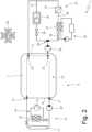
Figure 2 is a schematic view of some parts of the vehicle inFigure 1 ; -
Figure 3 is a perspective view of some parts of the vehicle inFigure 1 ; and -
Figure 4 is an enlarged view of a detail inFigure 3 . - In
Figure 1 , reference number 1 identifies, as a whole, a vehicle with electric drive provided with four drive wheels 2 (twofront drive wheels 2 and two rear drive wheels 2). - The vehicle 1 comprises an
electric drivetrain system 3 that is arranged at the front position (i.e., it is connected to the two front drive wheels 2) and anelectric drivetrain system 3 that is arranged at the rear position (i.e., it is connected to the two rear drive wheels 2), is structurally identical to theelectric drivetrain system 3 in the front position, and is mechanically independent and separate from theelectric drivetrain system 3 arranged at the front position. - According to another embodiment not illustrated, the vehicle 1 comprises a single electric drivetrain system 3 (arranged at the front position or arranged at the rear position) and, thus, only has two
drive wheels 2; in this embodiment, the vehicle 1 could also comprise a thermal drivetrain system connected to thedrive wheels 2 that do not receive the motion from the singleelectric drivetrain system 3. - Each
electric drivetrain system 3 comprises a pair of reversible electric machines 4 (i.e., that can function both as an electric motor absorbing electricity and generating mechanical torque, and as an electrical generator absorbing mechanical energy and generating electricity) provided with respective shafts and a pair oftransmissions 5 connecting the electric machines 4 (i.e. the shafts of the electric machines 4) to thecorresponding drive wheels 2 without the interposition of any clutch. - Each
electric machine 4 is driven by a corresponding electronic AC/DC power converter (i.e., an inverter), which is connected to apower storage system 6 provided with chemical batteries; i.e., each electronic AC/DC power converter is bi-directional and comprises a side in direct current connected to thepower storage system 6 and a side in alternating three-phase current that is connected to the correspondingelectric machine 4. - According to what is illustrated in
Figure 3 , thepower storage system 6 has a flat and (relatively) thin shape in order to be integrated inside of the vehicle 1 chassis. In particular, thepower storage system 6 comprises acontainer 7 that internally houses multiple modules provided with respective electrochemical cells with a parallelepipedal shape (i.e., having a "pouch" structure, or a prismatic structure). Thecontainer 7 has a lower wall (which constitutes the bottom of the vehicle 1 facing the road surface and is, of course, oriented horizontally), an upper wall that is parallel and opposite to the lower wall, afront wall 8 facing a front part of the vehicle 1 (i.e. facing the front of the vehicle 1 in relation to the froward direction D), and has arear wall 9 that is opposite thefront wall 8 and faces a rear part of the vehicle 1 (i.e. facing the back of the vehicle 1 in relation to the forward direction D). - According to what is illustrated in
Figure 2 , thepower storage system 6 is coupled to (integrated with) amain thermoregulation circuit 10 that is arranged inside the power storage system 6 (i.e., inside the container 7) and is configured to distribute a thermoregulation liquid (typically water-based) inside the power storage system 6 (i.e., inside the container 7). Themain thermoregulation circuit 10 has aninlet 11 for the thermoregulation liquid (i.e. a point in which the thermoregulation liquid enters the main thermoregulation circuit 10) arranged through thefront wall 8 of the power storage system 6 (i.e. of the container 7); in addition, themain thermoregulation circuit 10 has anoutlet 12 for the thermoregulation liquid (i.e. a point in which the thermoregulation liquid leaves the main thermoregulation circuit 10) arranged through thefront wall 8 of the power storage system 6 (i.e. of the container 7). In use, the thermoregulation liquid circulates through themain thermoregulation circuit 10 entering through theinlet 11 and leaving (in equal measure) through theoutlet 12. - The vehicle 1 comprises a
thermoregulation system 13, which is arranged in a front position in front of thefront wall 8 of the power storage system 6 (i.e., of the container 7) and is configured to cause the thermoregulation liquid to circulate in themain thermoregulation circuit 10 introducing the thermoregulation liquid into theinlet 11 and receiving (in equal measure) the thermoregulation liquid from theoutlet 12. In use, thethermoregulation system 13 cools the thermoregulation liquid (if thepower storage system 6 needs to be cooled) i.e., it heats the thermoregulation liquid (if thepower storage system 6 needs to be heated). - In the example embodiment illustrated in the attached figures, the
thermoregulation system 13 comprises aheat pump circuit 14 that is provided (among other things) with acompressor 15 and aheat exchanger 16 that exchanges heat with the thermoregulation liquid (i.e., it can both heat and cool the thermoregulation liquid). Obviously, theheat pump circuit 14 could be replaced with an electric heater and a conventional cooling circuit. Thethermoregulation system 13 preferably also comprises aradiator 17 that may be used (when the environmental conditions are right) to cool the thermoregulation liquid in combination with or alternately to theheat pump circuit 14. - The vehicle 1 comprises a
component 18 consisting of an on-board charger of thepower storage system 6; i.e., thecomponent 18 is used only when the vehicle 1 is parked, to recharge thepower storage system 6, using an external power source connected via cable. - The vehicle 1 comprises a
component 19 consisting of a DC/DC converter powering the low-voltage utilities of the vehicle 1 itself; i.e., only when the vehicle 1 is in use, the DC/DC converter transfers a part of the power stored at high voltage (several hundred nominal volts) in thepower storage system 6 into an additional low-voltage electrical circuit (typically 12 nominal volts and generally provided with its own backup battery) to which a series of low-voltage utilities of the vehicle 1 is connected. - The vehicle 1 comprises a
component 20 consisting of a hydraulic circuit used by an electronically controlled active suspension system; i.e., the active suspension system uses pressurised oil flowing in the hydraulic circuit to adjust the suspension response. - The
components rear wall 9 of the power storage system 6 (i.e., of the container 7) and, thus, are arranged opposite the thermoregulation system 13 (which is located at the front). - The vehicle 1 comprises a
secondary thermoregulation circuit 21 that is arranged at the rear position behind therear wall 9 of the power storage system 6 (i.e., of the container 7) and is coupled to threecomponents components components - The
main thermoregulation circuit 10 comprises adrawing point 22 that goes through therear wall 9 of the power storage system 6 (i.e., of the container 7) and supplies the thermoregulation liquid to thesecondary thermoregulation circuit 21; in addition, themain thermoregulation circuit 10 comprises areturn point 23 that goes through therear wall 9 of the power storage system 6 (i.e. of the container) and receives the thermoregulation liquid from thesecondary thermoregulation circuit 21. The twopoints main thermoregulation circuit 10; i.e., between thedrawing point 22 and thereturn point 23 themain thermoregulation circuit 10 only has one (short) connection pipe that does not perform thermal exchange with any component inside thepower storage system 6. - As a result, the
secondary thermoregulation circuit 21 uses the thermoregulation liquid that has been treated (i.e., cooled or heated) by thethermoregulation system 13 and drained (temporarily, i.e., "borrowed") from themain thermoregulation circuit 10 for its own operation. In fact, thesecondary thermoregulation circuit 21 is entirely free of components designed to cool the thermoregulation liquid, since thesecondary thermoregulation circuit 21 only has the function of circulating the thermoregulation liquid drained ("borrowed") from themain thermoregulation circuit 10 and treated (i.e., cooled or heated) by thethermoregulation system 13. - The
thermoregulation system 13 comprises a pump 24 (obviously arranged at the front position), which is configured to cause the thermoregulation liquid to circulate through themain thermoregulation circuit 10. In addition, thesecondary thermoregulation circuit 21 comprises a pump 25 (obviously arranged at the rear position), which is configured to cause the thermoregulation liquid to circulate through thesecondary thermoregulation circuit 21 by sucking the thermoregulation liquid from thedrawing point 22. In fact, without adequate sucking from thepump 25, only a minimum, negligible portion of the thermoregulation liquid would naturally flow through thesecondary thermoregulation circuit 21 from thedrawing point 21 to thereturn point 22. - The
secondary thermoregulation circuit 21 has abifurcation 26 in which thesecondary thermoregulation circuit 21 is bifurcated into abranch 27 along which only thecomponent 18 is arranged and abranch 28 along which thecomponents branches components return point 23. Thepump 25 is arranged upstream of thebifurcation 26, i.e., it is arranged between thedrawing point 22 and thebifurcation 26. - Along the
branch 27 an electronically controlledstop valve 29 is arranged that is designed to open or close the passage through thebranch 27; similarly, along thebranch 28, an electronically controlledstop valve 30 is arranged that is designed to open or close the passage through thebranch 28. - In particular, the component 20 (i.e., the hydraulic circuit used by the electronically controlled active suspension system) comprises a
heat exchanger 31 in which the pressurised oil flowing in the hydraulic circuit transfers heat to the thermoregulation liquid flowing along thebranch 28 of thesecondary thermoregulation circuit 21. - The vehicle 1 comprise a
control unit 32 monitoring the operation of thethermoregulation circuits control unit 32 is configured to always and only open onestop valve other stop valve component 18 requires thermoregulation (in particular, cooling) only when the vehicle 1 is parked while thecomponents control unit 32 is configured to drive thepump 25 only when thethermoregulation system 13 cools the thermoregulation liquid and only when thecomponents power storage system 6 needs to be heated (thus, the thermoregulation liquid is hotter than the external environment) there is never the need to heat thecomponents - According to a preferred embodiment, the
secondary thermoregulation circuit 21 has a nominal flow rate (for example, from 8-10 litres/minute) of the thermoregulation liquid that ranges between 10% and 35% of a nominal flow rate (for example, from 45-55 litres/minute) of the thermoregulation liquid of themain thermoregulation circuit 10. This condition makes it possible to ensure that the impact of the presence of thesecondary thermoregulation circuit 21 on themain thermoregulation circuit 10 is small and, thus, acceptable; in other words, the use of thesecondary thermoregulation circuit 21 entails, overall, an increase of a few degrees centigrade of the temperature of the thermoregulation liquid and this increase of a few degrees centigrade does not have a significant impact on the uniformity of the cooling ensured by themain thermoregulation circuit 10. In other words, due to the presence of thesecondary thermoregulation circuit 21, the temperature of the thermoregulation liquid at thereturn point 23 is a few degrees centigrade above the temperature of the thermoregulation liquid at thedrawing point 22; in any case, this increase in temperature of a few degrees centigrade of the thermoregulation liquid has no significant impact on the uniformity of the cooling ensured by themain thermoregulation circuit 10. - The embodiments described herein may be combined between them without departing from the scope of protection of this invention.
- The vehicle 1 described above has numerous advantages.
- In the first place, the vehicle 1 described above enables the cooling, when necessary, of the
components thermoregulation system 13 that is arranged at the rear position (i.e., arranged far from thecomponents - In addition, the vehicle 1 described above has no large hydraulic pipes that flow from the front to the rear, crossing the space of the passenger compartment, with a clear saving in weight and bulkiness. This result is obtained by using the whole
power storage system 6 as a large "pipe" to carry a small part of the thermoregulation liquid that has been treated (i.e., cooled or heated) by thethermoregulation system 13 from the front to the rear. - Finally, the vehicle 1 described above has very reduced costs and production complexity, since the only true change is the creation of the
points rear wall 9 of the power storage system 6 (i.e., of the container 7). -
- 1
- vehicle
- 2
- wheels
- 3
- drivetrain system
- 4
- electric machine
- 5
- transmission
- 6
- power storage system
- 7
- container
- 8
- front wall
- 9
- rear wall
- 10
- main thermoregulation circuit
- 11
- inlet
- 12
- outlet
- 13
- thermoregulation system
- 14
- heat pump circuit
- 15
- compressor
- 16
- radiator
- 17
- heat exchanger
- 18
- component
- 19
- component
- 20
- component
- 21
- secondary thermoregulation circuit
- 22
- drawing point
- 23
- return point
- 24
- pump
- 25
- pump
- 26
- bifurcation
- 27
- branch
- 28
- branch
- 29
- stop valve
- 30
- stop valve
- 31
- heat exchanger
- 32
- control unit
- D
- forward direction
Claims (11)
- A vehicle (1) comprising:at least one electric machine (4);a power storage system (6), which is arranged in a central position, has a front wall (8) facing a front part of the vehicle (1) and has a rear wall (9) opposite the front wall (8) and facing a rear part of the vehicle (1);a main thermoregulation circuit (10), which is arranged inside the power storage system (6), is configured to distribute a thermoregulation liquid within the power storage system (6) and has an inlet (11) for the thermoregulation liquid and an outlet (12) for the thermoregulation liquid;a thermoregulation system (13), which is arranged in a front position in front of the front wall (8) of the power storage system (6) and is configured to cause the thermoregulation liquid to circulate in the main thermoregulation circuit (10) introducing the thermoregulation liquid into the inlet (11) and receiving the thermoregulation liquid from the outlet (12);at least one component (18, 19, 20), which is arranged in a rear position behind the rear wall (9) of the power storage system (6); anda secondary thermoregulation circuit (21), which is arranged in a rear position behind the rear wall (9) of the power storage system (6) and is coupled to the component (18, 19, 20);the vehicle (1) is characterized in that the main thermoregulation circuit (10) comprises:a drawing point (22), which goes through the rear wall (9) of the power storage system (6) and supplies the thermoregulation liquid to the secondary thermoregulation circuit (21); anda return point (23), which goes through the rear wall (9) of the power storage system (6) and receives the thermoregulation liquid from the secondary thermoregulation circuit (21).
- The vehicle (1) according to claim 1, wherein the secondary thermoregulation circuit (21) is not provided with components designed to cool the thermoregulation liquid.
- The vehicle (1) according to claim 1 or 2, wherein:the thermoregulation system (13) comprises a first pump (24), which is configured to cause the thermoregulation liquid to circulate through the main thermoregulation circuit (10); andthe secondary thermoregulation circuit (21) comprises a second pump (25), which is configured to cause the thermoregulation liquid to circulate through the secondary thermoregulation circuit (21) by sucking the thermoregulation liquid from the drawing point (22).
- The vehicle (1) according to claim 3 and comprising a control unit (32), which is configured to operate the second pump (25) only when the thermoregulation system (13) cools the thermoregulation liquid and only when the component (18, 19, 20) needs to be cooled.
- The vehicle (1) according to one of the claims from 1 to 4 and comprising:a first component (18) consisting of an on-board charger of the power storage system (6); anda second component (19) consisting of a DC/DC converter powering low-voltage utilities.
- The vehicle (1) according to claim 5, wherein, in a bifurcation (26), the secondary thermoregulation circuit (21) branches off into a first branch (27), along which the first component (18) is arranged, and a second branch (28), along which the second component (19) is arranged.
- The vehicle (1) according to claim 6, wherein the secondary thermoregulation circuit (21) comprises a second pump (25), which is arranged upstream of the bifurcation (26) and is configured to cause the thermoregulation liquid to circulate through the secondary thermoregulation circuit (21) by sucking the thermoregulation liquid from the drawing point (22).
- The vehicle (1) according to claim 6 or 7 and comprising:a first stop valve (29), which is arranged along the first branch (27), and a second stop valve (30), which is arranged along the second branch (28); anda control unit (32), which is configured to always open one single stop valve (28; 29) at a time keeping the other stop valve (29; 28) closed.
- The vehicle (1) according to claim 6, 7 or 8 and comprising a third component (20), which is arranged along the second branch (28) in series to the first component (18) and consists of a hydraulic circuit used by an electronically controlled active suspension system.
- The vehicle (1) according to one of the claims from 6 to 9, wherein the two branches (27, 28) join one another downstream of the components (18, 19, 20) so as to flow together into the return point (23).
- The vehicle (1) according to one of the claims from 1 to 10, wherein the secondary thermoregulation circuit (21) has a nominal flow rate of the thermoregulation liquid ranging from 10% to 35% of a nominal flow rate of the thermoregulation liquid of the main thermoregulation circuit (10).
Applications Claiming Priority (2)
| Application Number | Priority Date | Filing Date | Title |
|---|---|---|---|
| IT102021000008633A IT202100008633A1 (en) | 2021-04-07 | 2021-04-07 | VEHICLE EQUIPPED WITH ELECTRIC TRACTION |
| PCT/IB2022/053258 WO2022215023A1 (en) | 2021-04-07 | 2022-04-07 | Electric drive vehicle |
Publications (2)
| Publication Number | Publication Date |
|---|---|
| EP4320002A1 EP4320002A1 (en) | 2024-02-14 |
| EP4320002B1 true EP4320002B1 (en) | 2024-10-02 |
Family
ID=77021762
Family Applications (1)
| Application Number | Title | Priority Date | Filing Date |
|---|---|---|---|
| EP22715201.4A Active EP4320002B1 (en) | 2021-04-07 | 2022-04-07 | Electric drive vehicle |
Country Status (6)
| Country | Link |
|---|---|
| US (1) | US12606053B2 (en) |
| EP (1) | EP4320002B1 (en) |
| JP (1) | JP2024513095A (en) |
| CN (1) | CN117561179A (en) |
| IT (1) | IT202100008633A1 (en) |
| WO (1) | WO2022215023A1 (en) |
Families Citing this family (3)
| Publication number | Priority date | Publication date | Assignee | Title |
|---|---|---|---|---|
| US20250121656A1 (en) * | 2023-10-13 | 2025-04-17 | Kubota Corporation | Liquid cooling system for an electric vehicle |
| US20250346089A1 (en) * | 2024-05-09 | 2025-11-13 | Ferrari S.P.A. | Motor vehicle provided with active suspensions and with a heat exchange system for managing heat of such active suspensions |
| FR3167122A1 (en) * | 2024-10-09 | 2026-04-10 | Ampere Sas | Layout of a motor vehicle underbody comprising a hollow body |
Family Cites Families (10)
| Publication number | Priority date | Publication date | Assignee | Title |
|---|---|---|---|---|
| JP5858229B2 (en) * | 2011-12-28 | 2016-02-10 | 三菱自動車工業株式会社 | Fire extinguishing structure for electric vehicles |
| US10476117B2 (en) * | 2014-12-04 | 2019-11-12 | Honda Motor Co., Ltd. | Vehicle power supply system |
| US10153524B2 (en) * | 2016-06-30 | 2018-12-11 | Faraday&Future Inc. | Vehicle cooling system using gravity based fluid flow |
| JP6879122B2 (en) * | 2017-08-24 | 2021-06-02 | 株式会社デンソー | Battery temperature controller |
| JP6904174B2 (en) * | 2017-08-31 | 2021-07-14 | ダイムラー・アクチェンゲゼルシャフトDaimler AG | Vehicle temperature control device |
| GB201714226D0 (en) * | 2017-09-05 | 2017-10-18 | Williams Advanced Eng Ltd | An electric vehicle, chassis and a vehicle cooling assembly |
| JP6830979B2 (en) * | 2019-05-16 | 2021-02-17 | 本田技研工業株式会社 | Cooling structure of vehicle battery unit |
| JP6830980B2 (en) * | 2019-05-16 | 2021-02-17 | 本田技研工業株式会社 | Cooling structure of vehicle battery unit |
| JP7156262B2 (en) * | 2019-12-19 | 2022-10-19 | トヨタ自動車株式会社 | vehicle with battery |
| US20230170552A1 (en) * | 2020-07-16 | 2023-06-01 | Audi Ag | Battery arrangement, motor vehicle and method for flooding a high-voltage battery |
-
2021
- 2021-04-07 IT IT102021000008633A patent/IT202100008633A1/en unknown
-
2022
- 2022-04-07 CN CN202280026849.9A patent/CN117561179A/en active Pending
- 2022-04-07 EP EP22715201.4A patent/EP4320002B1/en active Active
- 2022-04-07 US US18/553,760 patent/US12606053B2/en active Active
- 2022-04-07 WO PCT/IB2022/053258 patent/WO2022215023A1/en not_active Ceased
- 2022-04-07 JP JP2023561262A patent/JP2024513095A/en active Pending
Also Published As
| Publication number | Publication date |
|---|---|
| IT202100008633A1 (en) | 2022-10-07 |
| US20240190296A1 (en) | 2024-06-13 |
| CN117561179A (en) | 2024-02-13 |
| US12606053B2 (en) | 2026-04-21 |
| JP2024513095A (en) | 2024-03-21 |
| EP4320002A1 (en) | 2024-02-14 |
| WO2022215023A1 (en) | 2022-10-13 |
Similar Documents
| Publication | Publication Date | Title |
|---|---|---|
| US11898657B2 (en) | Thermal management system for electrified vehicle | |
| EP4320002B1 (en) | Electric drive vehicle | |
| US10252597B2 (en) | Joint active thermal management system and control logic for hybrid and electric vehicles | |
| US11731482B2 (en) | Integrated thermal management systems and associated thermal control methods for electrified vehicles | |
| EP2965935B1 (en) | Electric power system of a vehicle with electric propulsion | |
| US9819062B2 (en) | Traction battery assembly with thermal device | |
| US20160344075A1 (en) | Thermal Management System for a Vehicle | |
| US20130118000A1 (en) | Modular vehicle and associated method of construction | |
| US20160118700A1 (en) | Traction battery thermal management | |
| CA3081652A1 (en) | Temperature management systems and methods for electric vehicle | |
| CN114430135A (en) | Liquid cooled terminal block assembly | |
| CN105514310B (en) | Battery module | |
| US20260054604A1 (en) | Thermal management system for electrified vehicle using power electronics heat for heating a battery | |
| EP4309927B1 (en) | Electric drive vehicle provided with a thermoregulation system | |
| US11913554B2 (en) | Coolant distribution module for electrified vehicle | |
| US12330472B2 (en) | Thermal management system for managing heating and cooling of an electrified vehicle battery and cabin | |
| WO2024204540A1 (en) | Electric drive device for vehicle | |
| EP4450308A1 (en) | Electric vehicle | |
| US12522106B2 (en) | Thermal management system for electrified vehicle that provides battery and cabin heating off plug | |
| JP2024125760A (en) | Manifold | |
| JP2025151030A (en) | Vehicle control method and vehicle control device | |
| JP2025151031A (en) | Vehicle control method and vehicle control device |
Legal Events
| Date | Code | Title | Description |
|---|---|---|---|
| STAA | Information on the status of an ep patent application or granted ep patent |
Free format text: STATUS: UNKNOWN |
|
| STAA | Information on the status of an ep patent application or granted ep patent |
Free format text: STATUS: THE INTERNATIONAL PUBLICATION HAS BEEN MADE |
|
| PUAI | Public reference made under article 153(3) epc to a published international application that has entered the european phase |
Free format text: ORIGINAL CODE: 0009012 |
|
| STAA | Information on the status of an ep patent application or granted ep patent |
Free format text: STATUS: REQUEST FOR EXAMINATION WAS MADE |
|
| 17P | Request for examination filed |
Effective date: 20231020 |
|
| AK | Designated contracting states |
Kind code of ref document: A1 Designated state(s): AL AT BE BG CH CY CZ DE DK EE ES FI FR GB GR HR HU IE IS IT LI LT LU LV MC MK MT NL NO PL PT RO RS SE SI SK SM TR |
|
| GRAP | Despatch of communication of intention to grant a patent |
Free format text: ORIGINAL CODE: EPIDOSNIGR1 |
|
| STAA | Information on the status of an ep patent application or granted ep patent |
Free format text: STATUS: GRANT OF PATENT IS INTENDED |
|
| DAV | Request for validation of the european patent (deleted) | ||
| DAX | Request for extension of the european patent (deleted) | ||
| INTG | Intention to grant announced |
Effective date: 20240422 |
|
| GRAS | Grant fee paid |
Free format text: ORIGINAL CODE: EPIDOSNIGR3 |
|
| GRAA | (expected) grant |
Free format text: ORIGINAL CODE: 0009210 |
|
| STAA | Information on the status of an ep patent application or granted ep patent |
Free format text: STATUS: THE PATENT HAS BEEN GRANTED |
|
| AK | Designated contracting states |
Kind code of ref document: B1 Designated state(s): AL AT BE BG CH CY CZ DE DK EE ES FI FR GB GR HR HU IE IS IT LI LT LU LV MC MK MT NL NO PL PT RO RS SE SI SK SM TR |
|
| REG | Reference to a national code |
Ref country code: GB Ref legal event code: FG4D |
|
| REG | Reference to a national code |
Ref country code: CH Ref legal event code: EP |
|
| REG | Reference to a national code |
Ref country code: DE Ref legal event code: R096 Ref document number: 602022006525 Country of ref document: DE |
|
| REG | Reference to a national code |
Ref country code: IE Ref legal event code: FG4D |
|
| REG | Reference to a national code |
Ref country code: LT Ref legal event code: MG9D |
|
| REG | Reference to a national code |
Ref country code: NL Ref legal event code: MP Effective date: 20241002 |
|
| REG | Reference to a national code |
Ref country code: AT Ref legal event code: MK05 Ref document number: 1728230 Country of ref document: AT Kind code of ref document: T Effective date: 20241002 |
|
| PG25 | Lapsed in a contracting state [announced via postgrant information from national office to epo] |
Ref country code: NL Free format text: LAPSE BECAUSE OF FAILURE TO SUBMIT A TRANSLATION OF THE DESCRIPTION OR TO PAY THE FEE WITHIN THE PRESCRIBED TIME-LIMIT Effective date: 20241002 |
|
| PG25 | Lapsed in a contracting state [announced via postgrant information from national office to epo] |
Ref country code: NL Free format text: LAPSE BECAUSE OF FAILURE TO SUBMIT A TRANSLATION OF THE DESCRIPTION OR TO PAY THE FEE WITHIN THE PRESCRIBED TIME-LIMIT Effective date: 20241002 |
|
| PG25 | Lapsed in a contracting state [announced via postgrant information from national office to epo] |
Ref country code: HR Free format text: LAPSE BECAUSE OF FAILURE TO SUBMIT A TRANSLATION OF THE DESCRIPTION OR TO PAY THE FEE WITHIN THE PRESCRIBED TIME-LIMIT Effective date: 20241002 Ref country code: IS Free format text: LAPSE BECAUSE OF FAILURE TO SUBMIT A TRANSLATION OF THE DESCRIPTION OR TO PAY THE FEE WITHIN THE PRESCRIBED TIME-LIMIT Effective date: 20250202 Ref country code: PT Free format text: LAPSE BECAUSE OF FAILURE TO SUBMIT A TRANSLATION OF THE DESCRIPTION OR TO PAY THE FEE WITHIN THE PRESCRIBED TIME-LIMIT Effective date: 20250203 |
|
| PG25 | Lapsed in a contracting state [announced via postgrant information from national office to epo] |
Ref country code: FI Free format text: LAPSE BECAUSE OF FAILURE TO SUBMIT A TRANSLATION OF THE DESCRIPTION OR TO PAY THE FEE WITHIN THE PRESCRIBED TIME-LIMIT Effective date: 20241002 |
|
| PG25 | Lapsed in a contracting state [announced via postgrant information from national office to epo] |
Ref country code: BG Free format text: LAPSE BECAUSE OF FAILURE TO SUBMIT A TRANSLATION OF THE DESCRIPTION OR TO PAY THE FEE WITHIN THE PRESCRIBED TIME-LIMIT Effective date: 20241002 |
|
| PG25 | Lapsed in a contracting state [announced via postgrant information from national office to epo] |
Ref country code: ES Free format text: LAPSE BECAUSE OF FAILURE TO SUBMIT A TRANSLATION OF THE DESCRIPTION OR TO PAY THE FEE WITHIN THE PRESCRIBED TIME-LIMIT Effective date: 20241002 |
|
| PG25 | Lapsed in a contracting state [announced via postgrant information from national office to epo] |
Ref country code: NO Free format text: LAPSE BECAUSE OF FAILURE TO SUBMIT A TRANSLATION OF THE DESCRIPTION OR TO PAY THE FEE WITHIN THE PRESCRIBED TIME-LIMIT Effective date: 20250102 |
|
| PG25 | Lapsed in a contracting state [announced via postgrant information from national office to epo] |
Ref country code: GR Free format text: LAPSE BECAUSE OF FAILURE TO SUBMIT A TRANSLATION OF THE DESCRIPTION OR TO PAY THE FEE WITHIN THE PRESCRIBED TIME-LIMIT Effective date: 20250103 Ref country code: AT Free format text: LAPSE BECAUSE OF FAILURE TO SUBMIT A TRANSLATION OF THE DESCRIPTION OR TO PAY THE FEE WITHIN THE PRESCRIBED TIME-LIMIT Effective date: 20241002 Ref country code: LV Free format text: LAPSE BECAUSE OF FAILURE TO SUBMIT A TRANSLATION OF THE DESCRIPTION OR TO PAY THE FEE WITHIN THE PRESCRIBED TIME-LIMIT Effective date: 20241002 |
|
| PG25 | Lapsed in a contracting state [announced via postgrant information from national office to epo] |
Ref country code: CZ Free format text: LAPSE BECAUSE OF FAILURE TO SUBMIT A TRANSLATION OF THE DESCRIPTION OR TO PAY THE FEE WITHIN THE PRESCRIBED TIME-LIMIT Effective date: 20241002 Ref country code: PL Free format text: LAPSE BECAUSE OF FAILURE TO SUBMIT A TRANSLATION OF THE DESCRIPTION OR TO PAY THE FEE WITHIN THE PRESCRIBED TIME-LIMIT Effective date: 20241002 |
|
| PG25 | Lapsed in a contracting state [announced via postgrant information from national office to epo] |
Ref country code: RS Free format text: LAPSE BECAUSE OF FAILURE TO SUBMIT A TRANSLATION OF THE DESCRIPTION OR TO PAY THE FEE WITHIN THE PRESCRIBED TIME-LIMIT Effective date: 20250102 |
|
| PG25 | Lapsed in a contracting state [announced via postgrant information from national office to epo] |
Ref country code: SM Free format text: LAPSE BECAUSE OF FAILURE TO SUBMIT A TRANSLATION OF THE DESCRIPTION OR TO PAY THE FEE WITHIN THE PRESCRIBED TIME-LIMIT Effective date: 20241002 |
|
| REG | Reference to a national code |
Ref country code: DE Ref legal event code: R097 Ref document number: 602022006525 Country of ref document: DE |
|
| PGFP | Annual fee paid to national office [announced via postgrant information from national office to epo] |
Ref country code: DE Payment date: 20250428 Year of fee payment: 4 |
|
| PG25 | Lapsed in a contracting state [announced via postgrant information from national office to epo] |
Ref country code: DK Free format text: LAPSE BECAUSE OF FAILURE TO SUBMIT A TRANSLATION OF THE DESCRIPTION OR TO PAY THE FEE WITHIN THE PRESCRIBED TIME-LIMIT Effective date: 20241002 |
|
| PGFP | Annual fee paid to national office [announced via postgrant information from national office to epo] |
Ref country code: IT Payment date: 20250430 Year of fee payment: 4 |
|
| PG25 | Lapsed in a contracting state [announced via postgrant information from national office to epo] |
Ref country code: EE Free format text: LAPSE BECAUSE OF FAILURE TO SUBMIT A TRANSLATION OF THE DESCRIPTION OR TO PAY THE FEE WITHIN THE PRESCRIBED TIME-LIMIT Effective date: 20241002 |
|
| PGFP | Annual fee paid to national office [announced via postgrant information from national office to epo] |
Ref country code: FR Payment date: 20250424 Year of fee payment: 4 |
|
| PG25 | Lapsed in a contracting state [announced via postgrant information from national office to epo] |
Ref country code: RO Free format text: LAPSE BECAUSE OF FAILURE TO SUBMIT A TRANSLATION OF THE DESCRIPTION OR TO PAY THE FEE WITHIN THE PRESCRIBED TIME-LIMIT Effective date: 20241002 |
|
| PG25 | Lapsed in a contracting state [announced via postgrant information from national office to epo] |
Ref country code: SK Free format text: LAPSE BECAUSE OF FAILURE TO SUBMIT A TRANSLATION OF THE DESCRIPTION OR TO PAY THE FEE WITHIN THE PRESCRIBED TIME-LIMIT Effective date: 20241002 |
|
| PLBE | No opposition filed within time limit |
Free format text: ORIGINAL CODE: 0009261 |
|
| STAA | Information on the status of an ep patent application or granted ep patent |
Free format text: STATUS: NO OPPOSITION FILED WITHIN TIME LIMIT |
|
| PG25 | Lapsed in a contracting state [announced via postgrant information from national office to epo] |
Ref country code: SE Free format text: LAPSE BECAUSE OF FAILURE TO SUBMIT A TRANSLATION OF THE DESCRIPTION OR TO PAY THE FEE WITHIN THE PRESCRIBED TIME-LIMIT Effective date: 20241002 |
|
| 26N | No opposition filed |
Effective date: 20250703 |
|
| REG | Reference to a national code |
Ref country code: CH Ref legal event code: H13 Free format text: ST27 STATUS EVENT CODE: U-0-0-H10-H13 (AS PROVIDED BY THE NATIONAL OFFICE) Effective date: 20251125 |
|
| PG25 | Lapsed in a contracting state [announced via postgrant information from national office to epo] |
Ref country code: LU Free format text: LAPSE BECAUSE OF NON-PAYMENT OF DUE FEES Effective date: 20250407 |
|
| PG25 | Lapsed in a contracting state [announced via postgrant information from national office to epo] |
Ref country code: MC Free format text: LAPSE BECAUSE OF FAILURE TO SUBMIT A TRANSLATION OF THE DESCRIPTION OR TO PAY THE FEE WITHIN THE PRESCRIBED TIME-LIMIT Effective date: 20241002 |
|
| REG | Reference to a national code |
Ref country code: BE Ref legal event code: MM Effective date: 20250430 |
|
| PG25 | Lapsed in a contracting state [announced via postgrant information from national office to epo] |
Ref country code: BE Free format text: LAPSE BECAUSE OF NON-PAYMENT OF DUE FEES Effective date: 20250430 |
|
| PG25 | Lapsed in a contracting state [announced via postgrant information from national office to epo] |
Ref country code: CH Free format text: LAPSE BECAUSE OF NON-PAYMENT OF DUE FEES Effective date: 20250430 |
|
| PGFP | Annual fee paid to national office [announced via postgrant information from national office to epo] |
Ref country code: GB Payment date: 20260304 Year of fee payment: 5 |
|
| PG25 | Lapsed in a contracting state [announced via postgrant information from national office to epo] |
Ref country code: IE Free format text: LAPSE BECAUSE OF NON-PAYMENT OF DUE FEES Effective date: 20250407 |