EP4319987B1 - Optische reflexionssichtbare sicherheitskomponenten, herstellung solcher komponenten und mit solchen komponenten ausgestattete sicherheitsdokumente - Google Patents
Optische reflexionssichtbare sicherheitskomponenten, herstellung solcher komponenten und mit solchen komponenten ausgestattete sicherheitsdokumente Download PDFInfo
- Publication number
- EP4319987B1 EP4319987B1 EP22721758.5A EP22721758A EP4319987B1 EP 4319987 B1 EP4319987 B1 EP 4319987B1 EP 22721758 A EP22721758 A EP 22721758A EP 4319987 B1 EP4319987 B1 EP 4319987B1
- Authority
- EP
- European Patent Office
- Prior art keywords
- facets
- animation
- layer
- pattern
- optical security
- Prior art date
- Legal status (The legal status is an assumption and is not a legal conclusion. Google has not performed a legal analysis and makes no representation as to the accuracy of the status listed.)
- Active
Links
Images


Classifications
-
- B—PERFORMING OPERATIONS; TRANSPORTING
- B42—BOOKBINDING; ALBUMS; FILES; SPECIAL PRINTED MATTER
- B42D—BOOKS; BOOK COVERS; LOOSE LEAVES; PRINTED MATTER CHARACTERISED BY IDENTIFICATION OR SECURITY FEATURES; PRINTED MATTER OF SPECIAL FORMAT OR STYLE NOT OTHERWISE PROVIDED FOR; DEVICES FOR USE THEREWITH AND NOT OTHERWISE PROVIDED FOR; MOVABLE-STRIP WRITING OR READING APPARATUS
- B42D25/00—Information-bearing cards or sheet-like structures characterised by identification or security features; Manufacture thereof
- B42D25/30—Identification or security features, e.g. for preventing forgery
- B42D25/324—Reliefs
-
- B—PERFORMING OPERATIONS; TRANSPORTING
- B42—BOOKBINDING; ALBUMS; FILES; SPECIAL PRINTED MATTER
- B42D—BOOKS; BOOK COVERS; LOOSE LEAVES; PRINTED MATTER CHARACTERISED BY IDENTIFICATION OR SECURITY FEATURES; PRINTED MATTER OF SPECIAL FORMAT OR STYLE NOT OTHERWISE PROVIDED FOR; DEVICES FOR USE THEREWITH AND NOT OTHERWISE PROVIDED FOR; MOVABLE-STRIP WRITING OR READING APPARATUS
- B42D25/00—Information-bearing cards or sheet-like structures characterised by identification or security features; Manufacture thereof
- B42D25/30—Identification or security features, e.g. for preventing forgery
- B42D25/328—Diffraction gratings; Holograms
Definitions
- This description relates to the field of security marking. More particularly, it relates to optical security components visible in reflection for verifying the authenticity of a document, to a method of manufacturing such a component and to a secure document equipped with such a component.
- An optical security component described in the aforementioned application has a visible effect in reflection.
- the optical security component comprises a diffractive structure etched on a layer of a dielectric material.
- the structure has a first pattern comprising a bas-relief with a first set of facets whose shapes are determined to simulate a series of concave or convex cylindrical optical elements, visible in reflection, this first pattern being modulated by a second pattern forming a sub-wavelength network.
- Such an optical security component presents a dynamic visual effect of light bands of different colors and scrolling in opposite directions when it undergoes a tilt rotation around an axis parallel to one of the main directions of the cylindrical elements.
- the optical security component described in [Ref. 2] comprises a first layer of dielectric material and a diffractive structure etched on the first layer.
- the diffractive structure comprises a first pattern with a set of modules arranged side by side, along a given arrangement direction, a maximum width of each module, defined in the arrangement direction, being less than 300 ⁇ m.
- Each module comprises a bas-relief with a first set of facets whose shapes are determined to simulate an optical element visible in reflection, with at least one convex or concave region, said optical element having a profile with a continuously variable slope along a single direction, called the slope variation direction, perpendicular to the arrangement direction.
- the slope along at least one line parallel to the arrangement direction is different between said two modules.
- the minimum number of modules is determined by the maximum width of the modules, so that the diffractive structure is visible to the naked eye.
- Such an optical security component presents, in reflection and under the effect of a tilt movement around an axis parallel to said arrangement direction, a dynamic visual effect comprising the movement of one or more complex graphic elements, depending on the arrangement of said modules, and allows, compared to simple horizontal scrolling bars, more secure authentication and a stronger technological barrier, due to the design and manufacture of the modules necessary to obtain the visual effect described above.
- the first pattern can be modulated by a second pattern forming a periodic network of sub-wavelength period, determined to produce, after deposition of a second layer having a reflection spectral band in the visible, a resonant filter in a given spectral band, making it possible to combine the dynamic visual effect with a colored effect of order 0.
- WO 03/084764 [Ref. 4] describes a security element with optically active structures.
- the optically active structures comprise a diffraction structure formed by the additive or subtractive overlap of an overlap function (M) describing a macroscopic structure with a relief profile (R), for example a diffraction grating, the overlap function (M) being slowly variable relative to the relief profile (R).
- M overlap function
- R relief profile
- the present application describes an optical security component with an original structure allowing not only access to complex dynamic visual effects or "animations" as described in [Ref. 2] but also allowing continuous switching from an achromatic, white animation to the same iridescent animation, by a simple tilt movement of the optical security component over a wider angular range, ensuring even more robust authentication, by simple visual control and without specific equipment.
- the term “comprise” means the same as “include”, “contain”, and is inclusive or open and does not exclude other elements not described or shown. Furthermore, in this description, the term “approximately” or “substantially” means the same as “having a margin less than and/or more than 10%, for example 5%", of the respective value.
- the invention relates to an optical security component according to claim 1.
- a layer transparent in the visible range is defined as a layer having a transmission of at least 70%, preferably at least 80% for a wavelength included in the visible range, i.e. a wavelength between approximately 400 nm and approximately 800 nm.
- a layer thus transparent makes it possible to observe with the naked eye the layers located under the transparent layer.
- a set of "parallel" facets is a set of facets having a variation in slope in a single direction, called the "direction of variation of the slope".
- the slope of the facets can, however, vary in this direction, in opposite directions.
- the "height" of a facet is a distance between a lowest level of the facet and a highest level, the distance being measured along an axis perpendicular to a plane of the component.
- a rotation of the component along an axis contained in the plane of the component is generally called a "tilt movement" of the component.
- Such an optical security component exhibits, in reflection and under the effect of a simple tilt movement around an axis perpendicular to the direction of variation of the slope, a dynamic visual effect or achromatic, reflective and brilliant “animation” around the specular reflection, then the same iridescent animation which is linked with the achromatic animation on either side of the first part of the tilt angular range.
- Such an effect allows for more secure authentication and a stronger technological barrier, due to the design and manufacture of the component necessary to obtain the visual effect described above.
- Specular reflection in this description corresponds to the position of the component which allows a reflection of the incident light with an angle of reflection of opposite measurement to that of the incident angle.
- the normal to the plane of the component separates the angle of observation into two angular sectors of the same measurement.
- the observation angle is, for example, defined relative to a vertical lighting direction. According to one or more exemplary embodiments, the observation angle is between approximately 30° and approximately 60°. For example, the observation angle is equal to approximately 45°, which corresponds, for vertical lighting, to a conventional observation position for an observer.
- said minimum angular value of the slopes is equal to 0°.
- said maximum angular value of the slopes is between approximately 7° and approximately 15°.
- the positive direction for measuring the angular values of the slopes of the facets is the clockwise (or anti-trigonometric) direction.
- the facets have a dimension in the direction of the slope (or “width”) greater than or equal to approximately 4 times, advantageously greater than or equal to approximately 8 times, said period of the grating.
- the minimum dimension may therefore be chosen according to the period of the grating. For example, a minimum dimension of the width of the facets is equal to approximately 2 ⁇ m.
- the widths of the facets are between approximately 2 ⁇ m and approximately 100 ⁇ m, advantageously between approximately 2 ⁇ m and approximately 80 ⁇ m, advantageously about 4 ⁇ m and about 80 ⁇ m.
- the facets have a substantially rectangular shape and have a "length" measured in a direction perpendicular to the direction of the slope.
- the length is for example less than about 100 ⁇ m.
- all of the facets have a substantially identical height.
- the height of the facets is, for example, less than 2 microns, advantageously less than 1 micron.
- the facets of the set of facets have different heights.
- the facets have a maximum height. Said maximum height is, for example, less than 2 microns, advantageously less than 1 micron.
- At least some of the facets of the set of facets are arranged with variable slopes, the variation of which is increasing, respectively decreasing, in order to simulate a reflective element with a convex, respectively concave region.
- the visual effect resulting from such an arrangement of facets will be referred to as a "half-wave” type dynamic effect when the slopes of the facets have angular values whose variation is increasing or decreasing, but which are of the same sign.
- the visual effect resulting from such an arrangement of facets will be referred to as a "wave” type dynamic effect when the slopes of the facets have angular values whose variation is increasing or decreasing, and for which at least one change of sign is observed.
- a "wave” or "half-wave” type dynamic effect manifests itself for an observer, during a tilt movement of the component, as a continuous scrolling of a line of white light.
- the set of facets comprises one or more subsets of facets each configured to produce a dynamic “wave” type effect.
- said period of the diffraction grating, said maximum angular value of the slopes, measured in absolute value, and said observation angle are determined such that said first part of the tilt angular range comprises an angular superposition (overlap) with the second part of the tilt angular range of between approximately 1° and approximately 10°, preferably between approximately 3° and approximately 8°, for example equal to approximately 5°, on either side of the first part of the angular range.
- said period of the diffraction grating, said maximum angular value of the slopes, measured in absolute value, and said observation angle are determined such that the tilt angular range is between approximately 45° and approximately 120° (measured in air).
- said period of the diffraction grating, said maximum angular value of the slopes, measured in absolute value, and said observation angle are determined such that the first part of the tilt angular range is between approximately 15° and approximately 50° (measured in air), advantageously between approximately 20° and approximately 35° (measured in air).
- said period of the diffraction grating, said maximum angular value of the slopes, measured in absolute value, and said observation angle are determined such that the second part of the tilt angular range (measured in air) is comprised, on either side of the first tilt angular range, between approximately 30° and approximately 70°, advantageously between approximately 40° and approximately 60°.
- said one-dimensional diffraction grating is a sinusoidal profile diffraction grating.
- a sinusoidal profile grating is advantageous in that it allows symmetry of the diffraction efficiencies at orders +1 and -1 and therefore, symmetry in terms of visual efficiency for the iridescent animation on either side of the achromatic animation.
- grating profiles are possible, such as, for example and in a non-limiting manner, a diffraction grating with a pseudo-sinusoidal profile, defined as a sum of sinusoids with amplitudes and phases adjustable according to the expected profile, a diffraction grating with a rectangular profile, or any other advantageously symmetrical profile grating to have similar visual efficiency for the iridescent animation on either side of the achromatic animation.
- a depth of the diffraction grating is determined so as to optimize a diffraction efficiency of the grating at order 1 and at order -1 at at least one wavelength of the visible spectrum, for example at a central wavelength of the visible spectrum, for example around 550 nm.
- the second layer comprises a metallic material.
- the metallic material comprises one of the materials or an alloy of materials chosen from: Aluminum (Al), Silver (Ag), Chromium (Cr), Gold (Au), Copper (Cu).
- a thickness of the layer of metallic material is greater than about 2 to 3 times the skin thickness of the metal or alloy from which it is formed in the visible frequency range; for example, a thickness of the layer of metallic material is between about 20 nm and about 60 nm for aluminum.
- the dielectric material of the first layer has a first refractive index and the second layer comprises a dielectric material having a second refractive index such that the difference between the second refractive index and the first refractive index is greater than or equal to approximately 0.3, advantageously greater than or equal to approximately 0.5.
- said second layer comprises a material chosen from: zinc sulfide (ZnS), titanium dioxide (TiO 2 ) silicon nitride (Si 3 N 4 ).
- the material from which the second layer is formed makes it possible to give the component a spectral band of reflection in the visible and to make said first diffractive structure visible.
- Such materials suitable for said second layer are described for example in the patent US4856857 [Ref. 3].
- a minimum dimension of the first structure is greater than 300 ⁇ m, preferably greater than 1 mm, preferably greater than 2 mm, preferably greater than 5 mm. Such a minimum dimension makes it possible to make the structure visible to the naked eye.
- said first structure has an outline forming, seen from the observation face, a recognizable graphic shape.
- the optical security component according to the first aspect comprises at least one second structure etched on said first layer, said second layer at least partially covering said second structure.
- the second structure is configured to form, for example and in a non-limiting manner, a diffusing structure, a holographic structure, a diffracting structure making it possible to produce a so-called Alphagram® effect developed by the applicant.
- the structures may be juxtaposed, each with recognizable shapes.
- said first pattern has an outline forming, seen from the observation face, a recognizable graphic shape.
- said first pattern is interrupted in regions forming, seen from the observation face, a recognizable graphic object visible during the achromatic animation and during the iridescent animation.
- said first pattern is not modulated or is modulated by a third pattern forming a periodic network different from said second pattern, said second region forming, seen from the observation face, a recognizable graphic object visible only during the iridescent animation.
- the optical security component according to the first aspect comprises one or more additional layers depending on the needs of the application, without this or these additional layers contributing to the desired visual effect.
- the optical security component further comprises, on the side of the first observation face, a support film intended to be detached after transfer of the component onto the document or product.
- the optical security component is configured for the manufacture of a security track for securing banknotes, and comprises on the side of the first observation face and/or on the face opposite the first observation face, one or more protective layers.
- the present description relates to a secure object, for example a secure valuable document, comprising a substrate and an optical security component according to the first aspect, deposited on said substrate or on one of the layers of said substrate in the case of a multilayer substrate.
- Such a secure object is, for example, and without limitation: a banknote, an identity or travel document, on a paper or polymer substrate.
- the present description relates to methods of manufacturing security optical components according to the first aspect.
- the present description relates to a method of manufacturing an optical security component according to claim 14.
- FIG. 1A and the FIG. 1B schematically represent, in (partial) sectional views, two examples of optical security components according to the present description.
- the optical security component 101 shown in the FIG. 1A represents for example an optical security component intended to be transferred onto a document or a product for the purpose of securing it.
- it comprises a support film 111, for example a film made of polymer material, for example a polyethylene terephthalate (PET) film of a few tens of micrometers, typically 15 to 100 ⁇ m, as well as a detachment layer 112, for example made of natural or synthetic wax.
- PET polyethylene terephthalate
- the detachment layer makes it possible to remove the polymer support film 111 after transfer of the optical component onto the product or document to be secured.
- the optical security component 101 further comprises a first layer 113 made of dielectric material, having a first refractive index n 1 and at least one first diffractive structure S, comprising a first pattern M 1 , modulated by a second pattern M 2 forming a periodic grating, stamped on said first layer 113 and which will be described in more detail later.
- the optical security component 101 also comprises a second layer 114 at least partially covering said first structure S, and having a spectral band of reflection in the visible.
- the second layer 114 is for example a metallic layer or a so-called index variation layer having a refractive index different from that of the first, the difference in index between the layers 113 and 114 having a value at least equal to 0.3, advantageously a value at least equal to 0.5.
- the layer 114 makes it possible to ensure the reflection of the incident light.
- the optical security component also includes one or more optional layers, not optically functional but adapted to the application.
- the optical security component further comprises an adhesive layer 117, for example a heat-reactivatable adhesive layer, for transferring the optical security component onto the product or document.
- an adhesive layer 117 for example a heat-reactivatable adhesive layer, for transferring the optical security component onto the product or document.
- the optical security component can be manufactured by stacking the layers on the support film 111, then the component is transferred onto a document/product to be secured using the adhesive layer 117.
- the support film 111 can then be detached, for example by means of the detachment layer 112.
- the main observation face 100 of the optical security component is thus located on the side of the first layer 113 opposite the etched face of the layer 113.
- the optical safety component 102 shown in the FIG. 1B represents for example an optical security component intended for securing banknotes; it is for example a part of a security thread intended to be integrated into the paper during the manufacture of the note or a laminated track covering a window in the paper or a patch.
- the component 102 comprises as previously a support film 111 (12 to 25 ⁇ m) which will also serve as a protective film for the security thread, and, as in the example of the FIG.
- the optical security component 102 further comprises, in the example of the FIG. 1B , a set of optional layers 115, 116, 118.
- the layer 115 is for example a layer of dielectric material 115, for example a transparent layer; the layer 116 (optional) is for example a security layer 116, for example a discontinuous layer with a specific pattern printed locally with a UV ink to produce a additional marking that can be checked by eye or by machine; and the layer 118 (optional) is for example a protective layer, for example a second polymer film or a varnish.
- the layer 118 may be an adhesive layer.
- the manufacturing may be carried out by stacking the layers on the support film 111.
- the dielectric layer 115 and the security layer 116 may form only one layer.
- the protective layer (or adhesive layer) 118 and the layer 115 may also form only one and the same layer.
- the optical security component may be visible from both sides, with an inversion of the curvatures of the optical elements generated.
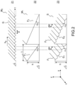
- FIG. 2 illustrates in more detail the parameters of a diffractive structure S (diagram 23) according to the present description.
- the structure S is formed of a first pattern M 1 comprising a set of facets F i (diagram 22), said pattern being at least partially modulated by a second pattern M 2 defined by the projection of a diffraction grating to a direction referenced G (diagram 21) and defined in a plane ⁇ parallel to the plane of the component (and therefore parallel to the observation face 100).
- All the facets Fi are parallel, that is to say they present a variation of the slope in a single and same direction, referenced y in the example of the FIG. 2 They are characterized by a height h, defined by the distance between a lowest level of the facet and a highest level, the distance being measured along an axis perpendicular to the plane ⁇ parallel to the plane of the component, namely along the z axis in the example of the FIG. 2 .
- the facets all have the same height h, said height being less than approximately 2 ⁇ m, advantageously less than approximately 1 ⁇ m, for example between approximately 0.5 ⁇ m and approximately 1 ⁇ m.
- the facets are also characterized by a width A, defined by the dimension along the y direction of variation of the slope, the width generally being for example between approximately 2 ⁇ m and approximately 100 ⁇ m, for example between approximately 2 ⁇ m and approximately 80 ⁇ m, for example approximately 4 ⁇ m and approximately 80 ⁇ m.
- a minimum width of the facets will be greater than approximately 4 times, advantageously greater than approximately 8 times, the period of the network.
- the facets generally have a substantially rectangular shape.
- the length will be sought to be less than approximately 100 ⁇ m, advantageously less than 60 ⁇ m, so as not to be visible to the eye.
- the facets F i comprise slopes whose angular values ⁇ i are included, in absolute value, between a minimum angular value, for example 0° and a maximum angular value, for example between approximately 7° and approximately 15°. As illustrated in the
- the positive direction chosen for the measurement of the angular values of the slopes is the clockwise or anti-trigonometric direction.
- the diffraction grating G is a one-way diffraction grating, characterized by a step or period d and a depth t.
- d a step or period
- t a depth
- k g the grating vector which is collinear with the direction y of variation of the slope and whose modulus is equal to 2 ⁇ / d .
- the structure S resulting from the modulation of the first pattern comprising all the facets by the diffraction grating G comprises a set of facets F i each supporting a one-dimensional diffraction grating G i .
- the facets F i each have an angle ⁇ i relative to the plane ⁇ parallel to the plane of the component.
- the projection onto each facet F i of a diffraction grating G with a constant pitch d and whose grating vector has a direction collinear with the direction y of variation of the slope can result in a projected grating G i with a variable pitch, referenced d Mi in diagram 23.
- the slopes of the facets having low angular values, typically less than 15° in absolute value, it will be possible to neglect in most of the exemplary embodiments, the effect of these variations in the grating pitch on the different facets.
- the diffraction grating G at order 1 has a sinusoidal profile.
- Other profiles are possible, such as a quasi-sinusoidal profile, defined as a sum of sinusoids with amplitudes and phases adjustable according to the expected profile, or a rectangular profile.
- Such symmetrical profiles have the advantage of having a diffraction efficiency similar to order + 1 and order -1.
- symmetrical grating profile we mean a grating whose profile has a central symmetry (with respect to a point).
- the structure recording process can be carried out for the purpose of manufacturing the optical security components, as will be described in more detail later.
- the period d of the diffraction grating, the maximum angular value ⁇ of the slopes, measured in absolute value, and the observation angle are determined to observe an achromatic animation in a first part of the angular tilt range around the specular reflection, and to observe the same animation, iridescent, in a second part of the angular tilt range, the iridescent animation being linked with the achromatic animation on either side of said first part of the angular tilt range.
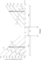
- FIG. 3 shows a diagram illustrating the desired sequence of iridescent animations and achromatic animation, during a tilt movement of an optical security component 40 according to the present description.
- ⁇ L the lighting axis, for example vertical lighting corresponding to natural light
- ⁇ O the observation axis corresponding to the direction of observation by an observer (symbolized by an eye on the FIG. 3 )
- ⁇ obs the observation angle between the axes ⁇ L and ⁇ O .
- tilt In operation, when checking the authenticity of a secure document using an optical security component conforming to the present description, the latter undergoes a rotation (tilt) around a tilt axis ⁇ contained in the plane of the component and substantially perpendicular to the direction of variation of the slope.
- the tilt axis is therefore substantially parallel to the x axis ( FIG. 2 ).
- the lighting and observation directions are fixed and the tilt movement of the component results in a variation of the angle of incidence ⁇ i of the light incident on the component, defined with respect to an axis ⁇ N normal to the plane of the component.
- the positive direction of the angle of incidence is the trigonometric direction.
- the diffraction angle ⁇ o is thus defined by the angle between the normal to the component and the direction of observation ⁇ O .
- the positive direction of the diffraction angle is, as for the angle of incidence, the trigonometric direction.
- the second part of the tilt angular range comprises an angular range ⁇ R- and an angular range ⁇ R+ corresponding respectively, from the point of view of an observer, to a tilt of the optical safety component backwards or forwards.
- Iridescent animation is a "rainbow" animation in which an observer sees the colors of the rainbow scroll by.
- textures namely red (texture 311), yellow (texture 312), green (texture 313), blue (texture 314).
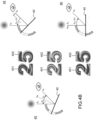
- FIGS 4A - 4C illustrate in more detail an example of a visual dynamic effect obtained with an optical security component according to the present description.
- the optical security component comprises in this example two diffractive structures according to the present description, a structure 401 forming a number “2” and a structure 402 forming a number “5”.
- the diffractive structures have contours delimited for example by demetallization, or more generally by localized removal of the reflective layer or in other embodiments, due to a delimitation of the structure itself.
- FIG. 4B illustrates the achromatic animation effect in the first tilt angular range referenced ⁇ B on the FIG. 3 .
- diagram 44 corresponds to the position of the optical safety component 40 referenced 4 on the FIG. 3
- diagram 45 corresponds to the position of the optical safety component 40 referenced 5 on the FIG. 3 (central position corresponding to specular reflection)
- diagram 46 corresponds to the position of the optical safety component 40 referenced 6 on the FIG. 3 .
- achromatic animation includes for example a movement of circular white lines on a black background.
- FIG. 5C represents a diagram of an arrangement of facets F i in a region of the structure used to form the digit "2" ( FIG. 4A - 4C ).
- ⁇ rec in the case of choosing a period d 2 of the diffraction grating.
- ⁇ ⁇ Rec arcsin n 1 sin ⁇ 2 ⁇ ⁇ T , n 1 ⁇ where the angle of incidence ⁇ 2 corresponds to the start of the iridescent animation if a period d 2 of the grating G was chosen instead of the optimal period d for which the overlap is zero:
- ⁇ 2 arcsin sin ⁇ obs , n 1 ⁇ ⁇ vis n 1 d 2 + 2 ⁇ max
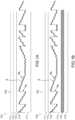
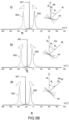
- the FIG.6 describes the diffracted wavelengths (orders +1 and -1) by different facets modulated by the grating G, returned towards the direction ⁇ O as a function of the angle of incidence, when the component is illuminated with white light according to the lighting direction ⁇ N .
- Curves 61, 62, 63, 64 and 65 correspond respectively to facets with angles -7.1°, -3.55°, 0°, +3.55° and +7.1°, overmodulated by a grating with a period of 520 nm.
- the curves are calculated using the equation giving d above, where ⁇ vis is replaced by the diffracted wavelength and d by the period chosen for the diffractive grating G.
- each of the facets modulated by the G grating diffracts a different wavelength in the direction of observation. This wavelength depends on the slope specific to each facet.
- the chromatic dispersion generated by the different facets modulated by the G grating follows the same graphic pattern previously defined on the first tilt range.
- curves 70, 71, 72 and 73 illustrate the efficiency curve of the grating at order -1 as a function of the grating depth for four grating periods, namely 400 nm, 460 nm, 520 nm, 580 nm respectively for an incident light wavelength corresponding to 550 nm.
- This curve makes it possible to optimize the value of the depth of the diffraction grating G.
- a depth t of 150 nm can be chosen to have a maximum diffraction efficiency at order 1 and -1.
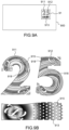
- FIG. 8 And 9A, 9B Examples of optical security components for securing valuable documents are illustrated by means of the FIG. 8 And 9A, 9B .
- FIG. 8 represents an example of an optical security component of the “patch” or stamp type according to the present description, for example a label, the patch being configured to be fixed for example on a banknote or a product.
- the optical security component comprises a stack of layers, for example a stack of layers as illustrated in the FIG. 1B , layer 118 then being able to be an adhesive layer.
- the security optical component comprises a first diffractive structure etched in the first layer (113, FIG. 1B ) and delimited by the contour referenced 81 on the FIG. 8 , this first diffractive structure being in accordance with the present description for generating an achromatic dynamic visual effect in a first tilt angular range and the same dynamic visual effect, but iridescent, in tilt angular ranges on either side of the first tilt angular range.
- the optical security component further comprises other structures delimited by the contours 82, 83 and 84. These may be, for example, diffusing structures, holographic structures or diffracting structures making it possible to produce so-called Alphagram ® effects.
- a reflective layer (114, FIG. 1B ), for example a metallic or high index layer, may be applied over the entire component, with regions 81, 82, 83, 84 being distinguished only by differences in the structure etched in the first layer.
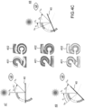
- FIG. 9A represents a diagram illustrating an example of a valuable document 900, for example a banknote, secured with an optical security component 91 according to the present description and the FIG. 9B represents a diagram showing an enlargement of the secure document illustrated in the FIG. 9A .
- the optical security component comprises a stack of layers, for example a stack of layers as illustrated in the FIG. 1A
- the layer 117 may be, for example, a layer of heat-reactivatable adhesive, for transferring the optical security component onto the support of the banknote 900.
- the security optical component 91 comprises a first diffractive structure etched in the first layer (113, FIG. 1B ) and delimited by the outline in the shape of a “2” referenced 911 on the FIG. 9A as well as a second diffractive structure etched in the first layer and delimited by the “5” shaped contour referenced 912.
- These two diffractive structures are diffractive structures in accordance with the present description for generating an achromatic dynamic visual effect in a first tilt angular range and the same dynamic visual effect, but iridescent, in tilt angular ranges on either side of the first tilt angular range.
- the animations resulting from the two diffractive structures can present different patterns.
- the second (reflective) layer is locally non-existent to allow regions 915 to appear in which the support of the banknote on which the optical security component is fixed appears.
- the reflective layer (114, FIG. 1A ) does not completely cover the diffractive structure.
- the first pattern forming said diffractive structure may have regions 918 in which there is no modulation with the first-order grating. These regions will not be perceptible when the optical security component undergoes a tilt movement in the first angular range (achromatic animation) but will appear black to an observer when the optical security component undergoes a tilt movement in the angular tilt ranges on either side of the first angular tilt range. It is thus possible to offer additional protection with a message that only appears in large tilt angles, during the iridescent animation.
- the 918 regions could be modulated by a second grating different from the first grating, for example a second grating of order 1 with pitch and/or orientation different from those of the first grating so as either to cause a spectral shift of the iridescence to appear, or to allow azimuthal control in the case where the orientation is different from the direction of the first grating of order 1 which modulates the rest of the first pattern.
- a second grating different from the first grating for example a second grating of order 1 with pitch and/or orientation different from those of the first grating so as either to cause a spectral shift of the iridescence to appear, or to allow azimuthal control in the case where the orientation is different from the direction of the first grating of order 1 which modulates the rest of the first pattern.
- the optical safety component illustrated on the FIGS 9A, 9B further comprises another structure delimited by the contour 913. It may be, for example, a diffractive structure comprising a set of facets as described in the present description but not modulated by a diffraction grating.
- the region 913 will present to an observer a dynamic achromatic visual effect.
- FIGS. 10A and 10B illustrate an example of an original “visual scenario”, obtained by means of an example of an optical security component according to the present description.
- FIG. 10A thus illustrates diagrams 1001 and 1002 respectively illustrating designs of a first pattern and a second pattern.
- the first pattern 1012 comprises a set of facets arranged according to the present description to produce, when the component is illuminated with white light along the lighting axis ⁇ L , a dynamic visual effect observable in reflection under the effect of a tilt movement and in the given tilt angular range ⁇ tilt .
- the first pattern is delimited in this example by a disc and interrupted in regions 1011, the regions 1011 forming a first recognizable graphic object, here the outline of a bulb and a base of the bulb.
- Diagram 1002 symbolizes the second pattern 1022, i.e. a network of order 1 (network G, FIG. 2 ) which modulates the first pattern. It is present throughout the first pattern except in regions 1021 which correspond on the one hand to regions 1011 in which there is no first pattern but also to additional regions which form a second recognizable graphic object, in this example a bulb filament and light rays.
- FIG. 10B shows diagrams illustrating, according to the predefined visual scenario, the achromatic and iridescent visual animations obtained thanks to the patterns as schematized on the FIG. 10A .
- an achromatic animation 1003 is observed over the entire component except at locations 1011 in which there is no first pattern. An observer therefore sees the outline of a bulb and the base during the achromatic animation (first graphic object).
- the animation continues in the second part of the tilt angle range but in an iridescent way thanks to the presence of the first diffractive grating of order 1, except at the locations corresponding to regions 1011 (no first pattern) and 1021 (no first pattern or second pattern).
- An observer thus sees the filament and the rays (second graphic object) appear during the iridescent animation, in addition to the outline of the bulb and the base.
- the resulting structure thus produces a blinking scenario during tilt between the first and second parts of the tilt angular range.
- the observer perceives a light bulb that "turns on” during the iridescent animation and "turns off” during the achromatic animation, the whole being visible on an animated disc-shaped background.
- a first step comprises the design of said at least one first diffractive structure according to the methods described above, and any other structures.
- the optical master is, for example, an optical medium on which the structure(s) are formed.
- the optical master can be formed by state-of-the-art electronic or optical lithography methods.
- the optical master is produced by etching a resist sensitive to electromagnetic radiation using an electron beam.
- the structure having the first pattern modulated by the second pattern can be etched in a single step.
- an optical lithography (or photolithography) technique can be used.
- the optical master is in this example a photosensitive resin plate and the origination step is carried out by one or more exposures of the plate by projections of masks, of the phase mask type and/or of the amplitude mask type, followed by development in an appropriate chemical solution.
- a first exposure is carried out by projection of amplitude masks whose transmission coefficients are adapted so that, after development, a relief corresponding to the first pattern is formed, in the regions in which the first pattern is provided.
- a second global exposure is carried out, according to interference photolithography methods known to those skilled in the art, a diffraction grating
- the step of metallic copying of the optical master can then be carried out, for example by electroplating, as mentioned above, in order to obtain the metallic matrix or "master".
- a step of matrix duplication of the metallic master can be carried out to obtain a large-scale production tool suitable for replicating the structure in industrial quantities.
- the manufacture of the optical security component then includes a replication step.
- the replication can be carried out by stamping (by hot embossing of the dielectric material) of the first layer 113 ( FIGS. 1A, 1B ) made of dielectric material with a refractive index of n 1 , for example a low index layer, typically a stamping varnish a few microns thick.
- the layer 113 is advantageously carried by the support film 111, for example a film of 12 ⁇ m to 100 ⁇ m made of polymer material, for example PET (polyethylene terephthalate).
- the replication can also be done by molding the stamping varnish layer before drying then UV crosslinking ("UV casting"). Replication by UV crosslinking makes it possible in particular to reproduce structures having a large depth range and makes it possible to obtain better fidelity in the replication.
- any other high-resolution replication method known from the prior art can be used in the replication step.
- the deposition on the layer thus embossed of all the other layers for example the reflective layer 114, the layer of dielectric material 115 (optional), the security layer 116 (optional) which can be deposited uniformly or selectively to represent a new pattern and the glue or varnish type layer (117, 118) by a coating process.
- optical security component according to the invention and the method of manufacturing said component comprise various variations, modifications and improvements which will be obvious to those skilled in the art, it being understood that these various variations, modifications and improvements are part of the scope of the invention as defined by the following claims.
Landscapes
- Diffracting Gratings Or Hologram Optical Elements (AREA)
- Credit Cards Or The Like (AREA)
Claims (14)
- Optische Sicherheitskomponente (101, 102), die dazu ausgestaltet ist, im Auflicht mit bloßem Auge entlang mindestens einer ersten Betrachtungsseite (100) in einer Betrachtungsrichtung (ΔO) betrachtet zu werden, die einen bestimmten Betrachtungswinkel (θobs) mit einer bestimmten Beleuchtungsrichtung (ΔL) bildet, die Komponente umfassend:- eine erste Schicht (113) aus dielektrischem Material, die im sichtbaren Bereich transparent ist;- mindestens eine erste diffraktive Struktur (S), die in die erste Schicht geätzt ist; und- eine zweite Schicht (114), die die erste diffraktive Struktur mindestens zum Teil bedeckt und ein Reflexionsspektralband im sichtbaren Bereich aufweist; und bei der:- die erste diffraktive Struktur ein erstes Muster (M1) umfasst, das aus einer Anordnung von parallelen Facetten (Fi) besteht, wobei die Facetten variable Neigungen entlang einer Änderungsrichtung (y) der Neigung aufweisen, wobei die Neigungen Winkelwerte umfassen, die als Absolutwert zwischen einem minimalen Winkelwert (αmin) und einem maximalen Winkelwert (αmax) liegen, wobei die Facetten eine bestimmte maximale Höhe (hm) umfassen, wobei die Anordnung von Facetten dazu ausgebildet ist, wenn die Komponente im Weißlicht entlang der Beleuchtungsachse beleuchtet wird, einen dynamischen visuellen Effekt zu erzeugen, der im Auflicht unter der Wirkung einer Kippbewegung entlang einer im Wesentlichen senkrecht zu der Änderungsrichtung der Neigung verlaufenden Kippachse (Δ) und in einem bestimmten Kippwinkelbereich (Δθtilt) betrachtbar ist;- das erste Muster, in mindestens einer ersten Region, durch ein zweites Muster (M2) moduliert wird, das ein eindimensionales periodisches Gitter mit der vorbestimmten Periode (d) zwischen 450 nm und 650 nm bildet, wobei das Gitter einen Gittervektor (kg) mit einer zu der Änderungsrichtung (y) der Neigung kollinearen Richtung umfasst, wobei das Gitter dazu bestimmt ist, nach dem Abscheiden der zweiten Schicht, eine diffraktive Wirkung im Auflicht mit der Ordnung 1 und mit der Ordnung -1 zu erzeugen,- wobei die Periode (d) des Gitters, der maximale Winkelwert (αmax) der Neigungen und der Betrachtungswinkel (θobs) bestimmt werden, um im Auflicht eine achromatische Animation in einem ersten Teil (ΔθB) des Kippwinkelbereichs um die Spiegelreflexion herum zu erzeugen und um dieselbe, irisierende, Animation in einem zweiten Teil (ΔθR-; ΔθR+) des Kippwinkelbereichs zu erzeugen, wobei sich die irisierende Animation mit der achromatischen Animation beidseits des ersten Teils des Kippwinkelbereichs überblendet.
- Optische Sicherheitskomponente nach Anspruch 1, bei welcher der erste Teil (ΔθB) des Kippwinkelbereichs eine Winkelüberlagerung mit dem zweiten Teil des Kippwinkelbereichs umfasst, die zwischen etwa 1° und etwa 10° beidseits des ersten Teils (ΔθB) des Winkelbereichs liegt.
- Optische Sicherheitskomponente nach einem der vorhergehenden Ansprüche, bei welcher der bestimmte Betrachtungswinkel (θobs) zwischen etwa 30° und etwa 60° liegt.
- Optische Sicherheitskomponente nach einem der vorhergehenden Ansprüche, bei welcher der minimale Winkelwert der Neigungen 0° beträgt.
- Optische Sicherheitskomponente nach einem der vorhergehenden Ansprüche, bei welcher der maximale Winkelwert der Neigungen zwischen etwa 7° und etwa 15° liegt.
- Optische Sicherheitskomponente nach einem der vorhergehenden Ansprüche, bei der sämtliche Facetten eine im Wesentlichen identische Höhe haben.
- Optische Sicherheitskomponente nach einem der vorhergehenden Ansprüche, bei der die Anordnung der Facetten eine oder mehrere Teilanordnungen von Facetten umfasst, die jeweils dazu ausgestaltet sind, eine "wellenartige" dynamische Wirkung zu erzeugen.
- Optische Sicherheitskomponente nach einem der vorhergehenden Ansprüche, bei der die zweite Schicht ein metallisches Material umfasst.
- Optische Sicherheitskomponente nach einem der Ansprüche 1 bis 7, bei der das dielektrische Material der ersten Schicht einen ersten Brechungsindex (n1) aufweist und die zweite Schicht ein dielektrisches Material umfasst, das einen zweiten Brechungsindex (n2) aufweist, derart, dass die Differenz zwischen dem zweiten Brechungsindex (n2) und dem ersten Brechungsindex (n1) größer oder gleich etwa 0,3 ist.
- Optische Sicherheitskomponente nach einem der vorhergehenden Ansprüche, bei der das erste Muster eine Kontur (911, 912) aufweist, die, von der Betrachtungsseite aus gesehen, eine wiedererkennbare grafische Form bildet.
- Optische Sicherheitskomponente nach einem der vorhergehenden Ansprüche, bei der das erste Muster in Regionen (1011) unterbrochen ist, die, von der Betrachtungsseite aus gesehen, ein wiedererkennbares grafisches Objekt bilden, das bei der achromatischen Animation und bei der irisierenden Animation sichtbar ist.
- Optische Sicherheitskomponente nach einem der vorhergehenden Ansprüche, bei der das erste Muster in mindestens einer zweiten Region (918, 1021) nicht moduliert wird oder durch ein drittes Muster moduliert wird, das ein von dem zweiten Muster verschiedenes periodisches Gitter bildet, wobei die zweite Region, von der Betrachtungsseite aus gesehen, ein wiedererkennbares grafisches Objekt bildet, das nur bei der irisierenden Animation sichtbar ist.
- Gesichertes Objekt, zum Beispiel gesichertes Wertdokument, umfassend ein Substrat und eine optische Sicherheitskomponente nach einem der vorhergehenden Ansprüche, die auf dem Substrat abgeschieden ist.
- Verfahren zur Herstellung einer optischen Sicherheitskomponente, die dazu bestimmt ist, im Auflicht mit bloßem Auge entlang einer Betrachtungsseite betrachtet zu werden, das Verfahren umfassend:- das Abscheiden einer ersten Schicht aus dielektrischem Material, die im sichtbaren Bereich transparent ist, auf einem Trägerfilm;- das Bilden mindestens einer ersten diffraktiven Struktur (S) auf der ersten Schicht derart, dass:- die erste diffraktive Struktur ein erstes Muster (M1) umfasst, das aus einer Anordnung von parallelen Facetten (Fi) besteht, wobei die Facetten variable Neigungen entlang einer Änderungsrichtung (y) der Neigung aufweisen, wobei die Neigungen Winkelwerte umfassen, die als Absolutwert zwischen einem minimalen Winkelwert (αmin) und einem maximalen Winkelwert (αmax) liegen, wobei die Facetten eine bestimmte maximale Höhe (hm) umfassen, wobei die Anordnung von Facetten dazu ausgebildet ist, wenn die Komponente im Weißlicht entlang der Beleuchtungsachse beleuchtet wird, einen dynamischen visuellen Effekt zu erzeugen, der im Auflicht unter der Wirkung einer Kippbewegung entlang einer im Wesentlichen senkrecht zu der Änderungsrichtung der Neigung verlaufenden Kippachse (Δ) und in einem bestimmten Kippwinkelbereich (Δθtilt) betrachtbar ist;- das erste Muster, in mindestens einer ersten Region, durch ein zweites Muster (M2) moduliert wird, das ein eindimensionales periodisches Gitter mit der vorbestimmten Periode (d) zwischen 450 nm und 650 nm bildet, wobei das Gitter einen Gittervektor (kg) mit einer zu der Änderungsrichtung (y) der Neigung kollinearen Richtung umfasst, wobei das Gitter dazu bestimmt ist, nach dem Abscheiden der zweiten Schicht, eine diffraktive Wirkung im Auflicht mit der Ordnung 1 und mit der Ordnung -1 zu erzeugen,- das Abscheiden einer zweiten Schicht, die die erste diffraktive Struktur mindestens zum Teil bedeckt und ein Reflexionsspektralband im sichtbaren Bereich aufweist; wobei:- die Periode (d) des Gitters, der maximale Winkelwert (αmax) der Neigungen und der Betrachtungswinkel (θobs) bestimmt werden, um im Auflicht, nach dem Abscheiden der zweiten Schicht, eine achromatische Animation in einem ersten Teil (ΔθB) des Kippwinkelbereichs um die Spiegelreflexion herum zu erzeugen und um dieselbe, irisierende, Animation in einem zweiten Teil (ΔθR-; ΔθR+) des Kippwinkelbereichs zu erzeugen, wobei sich die irisierende Animation mit der achromatischen Animation beidseits des ersten Teils des Kippwinkelbereichs überblendet.
Applications Claiming Priority (2)
| Application Number | Priority Date | Filing Date | Title |
|---|---|---|---|
| FR2103625A FR3121629B1 (fr) | 2021-04-09 | 2021-04-09 | Composants optiques de sécurité visibles en réflexion, fabrication de tels composants et documents sécurisés équipé de tels composants |
| PCT/EP2022/059511 WO2022214689A1 (fr) | 2021-04-09 | 2022-04-08 | Composants optiques de sécurité visibles en réflexion, fabrication de tels composants et documents sécurisés équipés de tels composants |
Publications (2)
| Publication Number | Publication Date |
|---|---|
| EP4319987A1 EP4319987A1 (de) | 2024-02-14 |
| EP4319987B1 true EP4319987B1 (de) | 2025-06-25 |
Family
ID=76601331
Family Applications (1)
| Application Number | Title | Priority Date | Filing Date |
|---|---|---|---|
| EP22721758.5A Active EP4319987B1 (de) | 2021-04-09 | 2022-04-08 | Optische reflexionssichtbare sicherheitskomponenten, herstellung solcher komponenten und mit solchen komponenten ausgestattete sicherheitsdokumente |
Country Status (5)
| Country | Link |
|---|---|
| EP (1) | EP4319987B1 (de) |
| CN (1) | CN117460625B (de) |
| FR (1) | FR3121629B1 (de) |
| MX (1) | MX2023011885A (de) |
| WO (1) | WO2022214689A1 (de) |
Family Cites Families (11)
| Publication number | Priority date | Publication date | Assignee | Title |
|---|---|---|---|---|
| KR860009325A (ko) | 1985-05-07 | 1986-12-22 | 기다지마 요시도시 | 투명형 홀로그램 |
| WO2002006858A2 (en) * | 2000-07-18 | 2002-01-24 | Optaglio Limited | Achromatic diffractive device |
| DE10216562C1 (de) * | 2002-04-05 | 2003-12-11 | Ovd Kinegram Ag Zug | Sicherheitselement mit Mikro- und Makrostrukturen |
| FR3019496A1 (fr) * | 2014-04-07 | 2015-10-09 | Hologram Ind | Composant optique de securite a effet reflectif, fabrication d'un tel composant et document securise equipe d'un tel composant |
| DE102015100520A1 (de) * | 2015-01-14 | 2016-07-28 | Leonhard Kurz Stiftung & Co. Kg | Mehrschichtkörper und Verfahren zu dessen Herstellung |
| DE102016007784A1 (de) * | 2016-06-24 | 2017-12-28 | Giesecke+Devrient Currency Technology Gmbh | Optisch variables Sicherheitselement |
| CN108656782B (zh) * | 2017-03-28 | 2020-07-10 | 中钞特种防伪科技有限公司 | 光学防伪元件、使用该光学防伪元件的产品及其制备方法 |
| FR3066954B1 (fr) | 2017-06-06 | 2019-11-01 | Surys | Composant optique de securite visible en reflexion, fabrication d'un tel composant et document securise equipe d'un tel composant |
| CN110936750A (zh) * | 2018-09-21 | 2020-03-31 | 中钞特种防伪科技有限公司 | 光学防伪元件及防伪产品 |
| CN109324418A (zh) * | 2018-10-30 | 2019-02-12 | 深圳市深大极光科技有限公司 | 防伪结构、全息烫印防伪膜及其制备方法 |
| CN111823749B (zh) * | 2019-04-19 | 2022-02-25 | 中钞特种防伪科技有限公司 | 光学防伪元件及其制作方法、光学防伪产品 |
-
2021
- 2021-04-09 FR FR2103625A patent/FR3121629B1/fr active Active
-
2022
- 2022-04-08 CN CN202280038284.6A patent/CN117460625B/zh active Active
- 2022-04-08 WO PCT/EP2022/059511 patent/WO2022214689A1/fr not_active Ceased
- 2022-04-08 MX MX2023011885A patent/MX2023011885A/es unknown
- 2022-04-08 EP EP22721758.5A patent/EP4319987B1/de active Active
Also Published As
| Publication number | Publication date |
|---|---|
| CN117460625A (zh) | 2024-01-26 |
| EP4319987A1 (de) | 2024-02-14 |
| MX2023011885A (es) | 2024-01-08 |
| FR3121629A1 (fr) | 2022-10-14 |
| FR3121629B1 (fr) | 2023-04-07 |
| WO2022214689A1 (fr) | 2022-10-13 |
| CN117460625B (zh) | 2024-12-31 |
Similar Documents
| Publication | Publication Date | Title |
|---|---|---|
| EP3129238B1 (de) | Optische sicherheitskomponente mit reflektierender wirkung, herstellung solch einer komponente und sicheres dokument mit solch einer komponente | |
| EP3634771B1 (de) | Optische, bei reflektion sichtbare sicherheitskomponente, herstellung solch einer komponente | |
| FR3051565B1 (fr) | Composant optique de securite et procede de fabrication d'un tel composant | |
| EP2836371B1 (de) | Optisches sicherheitselement, herstellung eines derartigem sicherheitselements und geschütztes produkt mit diesem element | |
| EP3969293B1 (de) | Optische sicherheitskomponente mit plasmonischem effekt, herstellung einer solchen komponente und sicheres dokument mit einer solchen komponente | |
| EP4251430B1 (de) | Personalisiertes bild aus einer metallschicht und einem linsenraster | |
| EP3899605B1 (de) | Vorrichtung zur anzeige eines oder mehrerer transitorischer bilder aus dreidimensionalen mikrostrukturen und verwendungen solch einer vorrichtung | |
| EP4366954B1 (de) | Optische sicherheitskomponenten, herstellung solcher komponenten und mit solchen komponenten ausgestattete sicherheitsdokumente | |
| EP4319987B1 (de) | Optische reflexionssichtbare sicherheitskomponenten, herstellung solcher komponenten und mit solchen komponenten ausgestattete sicherheitsdokumente | |
| EP4642653A1 (de) | Optische, im transmissionbereich sichtbare sicherheitskomponenten, herstellung solcher komponenten und mit solchen komponenten ausgestattete sichere objekte | |
| WO2024223226A1 (fr) | Composants optiques de sécurité, fabrication de tels composants et objets sécurisés équipés de tels composants | |
| WO2025067851A1 (fr) | Composants optiques de sécurité, fabrication de tels composants et objets sécurisés equipés de tels composants | |
| EP3727872B1 (de) | Optische, bei reflektion sichtbare sicherheitskomponente, herstellung solch einer komponente und sicheres dokument mit solch einer komponente | |
| WO2025237832A1 (fr) | Composants optiques de sécurité, fabrication de tels composants et objets sécurisés équipés de tels composants | |
| EP3137311B1 (de) | Optische sicherheitskomponente mit reflexionseffekt und herstellung solch einer komponente |
Legal Events
| Date | Code | Title | Description |
|---|---|---|---|
| STAA | Information on the status of an ep patent application or granted ep patent |
Free format text: STATUS: UNKNOWN |
|
| STAA | Information on the status of an ep patent application or granted ep patent |
Free format text: STATUS: THE INTERNATIONAL PUBLICATION HAS BEEN MADE |
|
| PUAI | Public reference made under article 153(3) epc to a published international application that has entered the european phase |
Free format text: ORIGINAL CODE: 0009012 |
|
| STAA | Information on the status of an ep patent application or granted ep patent |
Free format text: STATUS: REQUEST FOR EXAMINATION WAS MADE |
|
| 17P | Request for examination filed |
Effective date: 20231102 |
|
| AK | Designated contracting states |
Kind code of ref document: A1 Designated state(s): AL AT BE BG CH CY CZ DE DK EE ES FI FR GB GR HR HU IE IS IT LI LT LU LV MC MK MT NL NO PL PT RO RS SE SI SK SM TR |
|
| DAV | Request for validation of the european patent (deleted) | ||
| DAX | Request for extension of the european patent (deleted) | ||
| GRAP | Despatch of communication of intention to grant a patent |
Free format text: ORIGINAL CODE: EPIDOSNIGR1 |
|
| STAA | Information on the status of an ep patent application or granted ep patent |
Free format text: STATUS: GRANT OF PATENT IS INTENDED |
|
| GRAJ | Information related to disapproval of communication of intention to grant by the applicant or resumption of examination proceedings by the epo deleted |
Free format text: ORIGINAL CODE: EPIDOSDIGR1 |
|
| STAA | Information on the status of an ep patent application or granted ep patent |
Free format text: STATUS: REQUEST FOR EXAMINATION WAS MADE |
|
| INTG | Intention to grant announced |
Effective date: 20250218 |
|
| GRAP | Despatch of communication of intention to grant a patent |
Free format text: ORIGINAL CODE: EPIDOSNIGR1 |
|
| STAA | Information on the status of an ep patent application or granted ep patent |
Free format text: STATUS: GRANT OF PATENT IS INTENDED |
|
| INTC | Intention to grant announced (deleted) | ||
| GRAS | Grant fee paid |
Free format text: ORIGINAL CODE: EPIDOSNIGR3 |
|
| INTG | Intention to grant announced |
Effective date: 20250327 |
|
| GRAA | (expected) grant |
Free format text: ORIGINAL CODE: 0009210 |
|
| STAA | Information on the status of an ep patent application or granted ep patent |
Free format text: STATUS: THE PATENT HAS BEEN GRANTED |
|
| AK | Designated contracting states |
Kind code of ref document: B1 Designated state(s): AL AT BE BG CH CY CZ DE DK EE ES FI FR GB GR HR HU IE IS IT LI LT LU LV MC MK MT NL NO PL PT RO RS SE SI SK SM TR |
|
| REG | Reference to a national code |
Ref country code: GB Ref legal event code: FG4D Free format text: NOT ENGLISH |
|
| REG | Reference to a national code |
Ref country code: CH Ref legal event code: EP |
|
| REG | Reference to a national code |
Ref country code: DE Ref legal event code: R096 Ref document number: 602022016445 Country of ref document: DE |
|
| REG | Reference to a national code |
Ref country code: CH Ref legal event code: EP |
|
| REG | Reference to a national code |
Ref country code: IE Ref legal event code: FG4D Free format text: LANGUAGE OF EP DOCUMENT: FRENCH |
|
| PG25 | Lapsed in a contracting state [announced via postgrant information from national office to epo] |
Ref country code: FI Free format text: LAPSE BECAUSE OF FAILURE TO SUBMIT A TRANSLATION OF THE DESCRIPTION OR TO PAY THE FEE WITHIN THE PRESCRIBED TIME-LIMIT Effective date: 20250625 |
|
| REG | Reference to a national code |
Ref country code: LT Ref legal event code: MG9D |
|
| PG25 | Lapsed in a contracting state [announced via postgrant information from national office to epo] |
Ref country code: NO Free format text: LAPSE BECAUSE OF FAILURE TO SUBMIT A TRANSLATION OF THE DESCRIPTION OR TO PAY THE FEE WITHIN THE PRESCRIBED TIME-LIMIT Effective date: 20250925 Ref country code: GR Free format text: LAPSE BECAUSE OF FAILURE TO SUBMIT A TRANSLATION OF THE DESCRIPTION OR TO PAY THE FEE WITHIN THE PRESCRIBED TIME-LIMIT Effective date: 20250926 |
|
| PG25 | Lapsed in a contracting state [announced via postgrant information from national office to epo] |
Ref country code: HR Free format text: LAPSE BECAUSE OF FAILURE TO SUBMIT A TRANSLATION OF THE DESCRIPTION OR TO PAY THE FEE WITHIN THE PRESCRIBED TIME-LIMIT Effective date: 20250625 |
|
| PG25 | Lapsed in a contracting state [announced via postgrant information from national office to epo] |
Ref country code: RS Free format text: LAPSE BECAUSE OF FAILURE TO SUBMIT A TRANSLATION OF THE DESCRIPTION OR TO PAY THE FEE WITHIN THE PRESCRIBED TIME-LIMIT Effective date: 20250925 |
|
| PG25 | Lapsed in a contracting state [announced via postgrant information from national office to epo] |
Ref country code: LV Free format text: LAPSE BECAUSE OF FAILURE TO SUBMIT A TRANSLATION OF THE DESCRIPTION OR TO PAY THE FEE WITHIN THE PRESCRIBED TIME-LIMIT Effective date: 20250625 |
|
| REG | Reference to a national code |
Ref country code: NL Ref legal event code: MP Effective date: 20250625 |
|
| PG25 | Lapsed in a contracting state [announced via postgrant information from national office to epo] |
Ref country code: NL Free format text: LAPSE BECAUSE OF FAILURE TO SUBMIT A TRANSLATION OF THE DESCRIPTION OR TO PAY THE FEE WITHIN THE PRESCRIBED TIME-LIMIT Effective date: 20250625 |
|
| PG25 | Lapsed in a contracting state [announced via postgrant information from national office to epo] |
Ref country code: PT Free format text: LAPSE BECAUSE OF FAILURE TO SUBMIT A TRANSLATION OF THE DESCRIPTION OR TO PAY THE FEE WITHIN THE PRESCRIBED TIME-LIMIT Effective date: 20251027 |
|
| REG | Reference to a national code |
Ref country code: AT Ref legal event code: MK05 Ref document number: 1806104 Country of ref document: AT Kind code of ref document: T Effective date: 20250625 |
|
| PG25 | Lapsed in a contracting state [announced via postgrant information from national office to epo] |
Ref country code: IS Free format text: LAPSE BECAUSE OF FAILURE TO SUBMIT A TRANSLATION OF THE DESCRIPTION OR TO PAY THE FEE WITHIN THE PRESCRIBED TIME-LIMIT Effective date: 20251025 |
|
| PG25 | Lapsed in a contracting state [announced via postgrant information from national office to epo] |
Ref country code: AT Free format text: LAPSE BECAUSE OF FAILURE TO SUBMIT A TRANSLATION OF THE DESCRIPTION OR TO PAY THE FEE WITHIN THE PRESCRIBED TIME-LIMIT Effective date: 20250625 Ref country code: SM Free format text: LAPSE BECAUSE OF FAILURE TO SUBMIT A TRANSLATION OF THE DESCRIPTION OR TO PAY THE FEE WITHIN THE PRESCRIBED TIME-LIMIT Effective date: 20250625 |