EP4319519A1 - Cooling apparatus - Google Patents
Cooling apparatus Download PDFInfo
- Publication number
- EP4319519A1 EP4319519A1 EP22798817.7A EP22798817A EP4319519A1 EP 4319519 A1 EP4319519 A1 EP 4319519A1 EP 22798817 A EP22798817 A EP 22798817A EP 4319519 A1 EP4319519 A1 EP 4319519A1
- Authority
- EP
- European Patent Office
- Prior art keywords
- flexible pipe
- cooling
- heat medium
- heat
- cooling member
- Prior art date
- Legal status (The legal status is an assumption and is not a legal conclusion. Google has not performed a legal analysis and makes no representation as to the accuracy of the status listed.)
- Pending
Links
Images




Classifications
-
- H—ELECTRICITY
- H05—ELECTRIC TECHNIQUES NOT OTHERWISE PROVIDED FOR
- H05K—PRINTED CIRCUITS; CASINGS OR CONSTRUCTIONAL DETAILS OF ELECTRIC APPARATUS; MANUFACTURE OF ASSEMBLAGES OF ELECTRICAL COMPONENTS
- H05K7/00—Constructional details common to different types of electric apparatus
- H05K7/20—Modifications to facilitate cooling, ventilating, or heating
- H05K7/20709—Modifications to facilitate cooling, ventilating, or heating for server racks or cabinets; for data centers, e.g. 19-inch computer racks
- H05K7/20763—Liquid cooling without phase change
- H05K7/20772—Liquid cooling without phase change within server blades for removing heat from heat source
-
- H—ELECTRICITY
- H05—ELECTRIC TECHNIQUES NOT OTHERWISE PROVIDED FOR
- H05K—PRINTED CIRCUITS; CASINGS OR CONSTRUCTIONAL DETAILS OF ELECTRIC APPARATUS; MANUFACTURE OF ASSEMBLAGES OF ELECTRICAL COMPONENTS
- H05K7/00—Constructional details common to different types of electric apparatus
- H05K7/20—Modifications to facilitate cooling, ventilating, or heating
- H05K7/20218—Modifications to facilitate cooling, ventilating, or heating using a liquid coolant without phase change in electronic enclosures
- H05K7/20254—Cold plates transferring heat from heat source to coolant
-
- H—ELECTRICITY
- H10—SEMICONDUCTOR DEVICES; ELECTRIC SOLID-STATE DEVICES NOT OTHERWISE PROVIDED FOR
- H10W—GENERIC PACKAGES, INTERCONNECTIONS, CONNECTORS OR OTHER CONSTRUCTIONAL DETAILS OF DEVICES COVERED BY CLASS H10
- H10W40/00—Arrangements for thermal protection or thermal control
- H10W40/40—Arrangements for thermal protection or thermal control involving heat exchange by flowing fluids
- H10W40/47—Arrangements for thermal protection or thermal control involving heat exchange by flowing fluids by flowing liquids, e.g. forced water cooling
Definitions
- the present disclosure relates to a technology of cooling a heat-generating member.
- PTLs 1 and 2 disclose technologies of cooling a heat-generating member to be cooled by supplying a heat medium to a stack of the heat-generating member and the cooling member.
- a plurality of cooling targets may be installed in one device.
- a pipe for supplying a refrigerant to the cooling member may be a pipe using a highly flexible material such as rubber.
- Independently connecting to each cooling target the pipes for supplying a heat medium from the outside of the device may increase the number of pipes in the device. Increased number of pipes may compress the inside of the device. The compressed inside of the device may increase the temperature inside the device, for example.
- the device may become larger.
- PTLs 1 and 2 assume that the cooling target and the pipe for supplying to the cooling member are fixed. Therefore, PTLs 1 and 2 do not assume the above situation.
- the present disclosure was accomplished in light of the above mentioned problems and one objective thereof is to provide a cooling apparatus or the like that may suppress an increase in the number of pipes.
- a cooling apparatus includes: a first flexible pipe at least a part of which is arranged inside a housing and through which a heat medium supplied from an outside of the housing passes, the housing including a plurality of modules installed in the housing, each of the plurality of modules including an electronic circuit board including a heat-generating member and a cooling member that receives heat from the heat-generating member and cools the heat-generating member by using the heat medium; and a branching member that causes the heat medium to branch from the first flexible pipe into the cooling member and a second flexible pipe, the cooling member being included in any one of the plurality of modules, the second flexible pipe supplying the heat medium to the cooling member included in any other module of the plurality of modules.
- the increase in the number of pipes may be suppressed.
- Fig. 1 is a plan view illustrating an example of a configuration of a cooling apparatus 100.
- the cooling apparatus 100 includes a first flexible pipe 10 and a branching member 11.
- a housing 200 includes a plurality of modules disposed in it.
- a module 1 shown in Fig. 1 is an example of a module disposed in a housing.
- the module 1 includes, for example, an electronic circuit board 15 including a heat-generating member 14, and a cooling member 12.
- the cooling member 12 is disposed on the heat-generating member 14.
- the cooling member 12 is a member that receives heat from the heat-generating member 14.
- the cooling member 12 is supplied with a heat medium from a branching member, and causes the heat medium to receive the heat received from the heat-generating member 14.
- the cooling member 12 may cool the heat-generating member 14 by using the heat medium as described above.
- the heat medium passes through the inside of the first flexible pipe 10, the branching member 11, and a second flexible pipe 13.
- the first flexible pipe has a first end connected to the branching member 11.
- the first flexible pipe has a second end connected to, for example, a pump or radiator or the like that supplies the heat medium, although is not shown in Fig. 1 .
- the second flexible pipe 13 has a first end connected to the branching member 11.
- the second flexible pipe 13 has a second end that is connected to, for example, any other module of the plurality of modules that is different from the module 1 or the like, although is not shown in Fig. 1 .
- the flexible pipe is, for example, a pipe made of a highly flexible material such as ethyleme propylene diene monomer (EPDM) rubber.
- EPDM ethyleme propylene diene monomer
- the flexible pipe is also referred to as a hose or tube.
- Fig. 2 is a cross-sectional view of an example of the configuration of the cooling apparatus 100. Specifically, Fig. 2 is a cross-sectional view taken along line A-A in Fig. 1 . Arrows shown in Fig. 2 indicate directions in which the heat medium passes.
- the heat medium supplied from the outside of the housing passes through the first flexible pipe 10 and is supplied to the branching member 11.
- the branching member 11 causes the heat medium supplied from the first flexible pipe 10 to branch into the cooling member 12 and the second flexible pipe 13.
- the second flexible pipe 13 supplies the heat medium flowing in from the branching member 11 to the cooling member included in any other module of the plurality of modules.
- the second flexible pipe 13 is supplied with a heat medium not directly affected by heat generation by the heat-generating member 14.
- the cooling apparatus 100 of the first example embodiment includes, a first flexible pipe, at least a part of which is arranged inside a housing in which a plurality of modules is installed, each module including an electronic circuit board that includes a heat-generating member and a cooling member that receives heat from the heat-generating member and uses a heat medium to cool the heat-generating member, and through which the heat medium supplied from the outside of the housing passes, and a branching member that causes the heat medium from the first flexible pipe to branch into the cooling member included in any one of the plurality of modules and into a second flexible pipe that supplies the heat medium to the cooling member included in any other module of the plurality of modules, And the branching member is provided together with the cooling member.
- the cooling apparatus 100 may supply the heat medium to the cooling member of each module, without independently providing to each module a pipe that supplies the heat medium from the outside of the housing, for example.
- the cooling apparatus 100 of the first example embodiment may suppress the increase in the number of pipes.
- the heat medium flowing into the second flexible pipe is not directly affected by heat generation by the heat-generating member.
- the cooling apparatus 100 of the first example embodiment may also supply a heat medium with suppressed temperature rise to the cooling members of other modules.
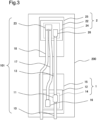
- Fig. 3 is a plan view illustrating an example of a configuration of a cooling apparatus 101 of the second example embodiment.
- a housing 200 is mounted with a module 1 and a module 2.
- the module 1 includes an electronic circuit board 15 including a heat-generating member 14, and a cooling member 12.
- the module 2 includes an electronic circuit board 25 including a heat-generating member 24, and a cooling member 22.
- the heat-generating members 14, 24 are, for example, a control processing unit (CPU) and a memory or the like, although are not limited to those examples.
- the cooling member 22 is a member that may cool the heat-generating member 24.
- the cooling member 22 is disposed on the heat-generating member 24, may cool the heat-generating member 24 by causing the heat medium to receive the heat received from the heat-generating member 24 heat.
- the cooling members 12, 22 may also be referred to as cold plates.
- the cooling member 12 may be referred to as a first cooling member, and the cooling member 22 may be referred to as a second cooling member.
- the module 1 and module 2 may be cooled by the cooling member in the same manner, but may be different devices.
- another member may be mounted on the module 1 and module 2.
- the cooling member 12 is provided with a branching member 11 and a connection joint 16.
- the connection joint 16 connects the cooling member 12 with a third flexible pipe 17. In other words, the heat medium discharged from the cooling member 12 passes through the connection joint 16 and flows into the third flexible pipe 17.
- the cooling member 22 is provided with a connection joint 26 and a joining member 23.
- the connection joint 26 connects the cooling member 22 with the second flexible pipe 13. In other words, the heat medium flowing through the second flexible pipe 13 passes through the connection joint 26 and is supplied to the cooling member 22.
- the joining member 23 joins the heat medium discharged from the cooling member 12 provided together with the branching member 11 and the heat medium discharged from the cooling member 22. More specifically, the joining member 23 connects the cooling member 22, the third flexible pipe 17, and a fourth flexible pipe 18. In other words, the joining member 23 joins the heat medium discharged from the cooling member 22 and the heat medium flowing in from the third flexible pipe 17 and discharges the heat medium to the fourth flexible pipe 18.
- the first flexible pipe 10 supplies a heat medium supplied from a pump or radiator or the like (not shown) outside the housing 200 to the branching member 11.
- the branching member 11 causes the heat medium to branch into the cooling member 12 and second flexible pipe 13.
- the heat medium is supplied to the first flexible pipe 10 at a flow rate of 2 L/min (liters per minute).
- the branching member 11 supplies the heat medium to each of the cooling member 12 and second flexible pipe 13 at a flow rate of 1 L/min.
- the flexible pipes may have different pipe diameters according to the flow rate.
- the first flexible pipe 10 may have a pipe diameter larger than the pipe diameter of the second flexible pipe 13.
- the heat medium flowing through the cooling member 12 receives heat from the heat-generating member 14 and cooling member 12, passes through the connection joint 16 and third flexible pipe 17, and flows into the joining member 23.
- the heat medium supplied from the branching member 11 to the second flexible pipe 13 passes through the connection joint 26 and flows into the cooling member 22.
- the heat medium flowing through the cooling member 22 receives heat from the heat-generating member 24 and cooling member 22 and flows into the joining member 23. Then, the heat medium flows in from the joining member 23 into the fourth flexible pipe 18.
- the fourth flexible pipe 18 is connected to, for example, a radiator or the like outside the housing 200. In other words, the heat medium that receives heat in the housing 200 passes through the fourth flexible pipe 18 and is cooled by a radiator or the like.
- the cooled heat medium is supplied again to the first flexible pipe 10.
- the cooling apparatus 101 of the second example embodiment includes, a first flexible pipe, at least a part of which is arranged inside a housing in which a plurality of modules is installed, each module including an electronic circuit board that includes a heat-generating member and a cooling member that receives heat from the heat-generating member and uses a heat medium to cool the heat-generating member, and through which the heat medium supplied from the outside of the housing passes, and a branching member for branching the heat medium from the first flexible pipe into the cooling member included in the module and a second flexible pipe. And the branching member is provided together with the cooling member. This provides the same effect as the cooling apparatus 100 of the first example embodiment.
- the cooling apparatus 101 of the second example embodiment further includes a second flexible pipe, and a joining member that joins the heat medium discharged from the first cooling member that is a cooling member provided together with the branching member and the heat medium discharged from the second cooling member.
- the second cooling member is a cooling member included in other modules.
- Fig. 4 is a plan view illustrating an example of a configuration of a cooling apparatus 101 of a modified example 1.
- the cooling member 12 is provided with the branching member 11 and the joining member 23.
- the cooling member 22 is provided with connection joints 26, 27.
- the heat medium that passes through the cooling member 22 passes through the connection joint 27 and flows into the third flexible pipe 17.
- the joining member 23 joins the heat medium flowing in from the third flexible pipe and the heat medium discharged from the cooling member 12. Then, the heat medium discharged from the joining member 23 flows into the fourth flexible pipe 18.
- the joining member is provided together with the first cooling member, and joins the heat medium flowing in from the third flexible pipe and the heat medium discharged from the first cooling member. At this time, the heat medium discharged from the second cooling member passes through the third flexible pipe.
- Such a configuration may suppress the compression by the pipes in the housing more than the cooling apparatus in Fig. 3 .
- the housing 200 may have three or more modules installed in it.
- the connection joint 26 may be replaced with a branching member, and the branching member may supply the heat medium to a cooling member included in a module different from the modules 1, 2.
- the cooling member and branching member are connected by a flexible pipe and a connection joint.
- a cooling apparatus of a third example embodiment will now be described. Some contents overlapping with the contents described in the first and second example embodiments will be omitted.
- Fig. 5 is a perspective view illustrating an example of a configuration of an electronic device 1000 including a cooling apparatus 102 of the third example embodiment.
- the electronic device 1000 may be, for example, a server.
- a plurality of electronic devices 1000 may be contained in a server rack (not shown), and the plurality of electronic devices 1000 may operate as a set of servers.
- the electronic device 1000 includes a housing 300, a main substrate 9, a cooling apparatus 102, and a plurality of modules.
- the main substrate 9, the cooling apparatus 102, and the plurality of modules are contained in the housing 300.
- the main substrate 9 and the plurality of modules are connected.
- the plurality of modules include modules 3A, 3B, 4A, 4B, 5A, 5B, 6A, 6B, and 8.
- the module 5A is disposed on the module 5B (in other words, in the +z-axis direction).
- the modules 3A, 4A, and 6A are disposed on the modules 3B, 4B, and 6B (in the +z-axis direction), respectively.
- the modules 3A, 4A, 5A, 6A, and 8 are connected via a plurality of flexible pipes.
- a configuration including the modules 3A, 4A, 5A, 6A, and 8 is referred to as an upper configuration of the electronic device 1000.
- a configuration including the modules 3B, 4B, 5B, and 6B is referred to as a lower configuration of the electronic device 1000.
- the modules 3A, 3B may be collectively referred to as a module 3.
- configurations given with symbols including the same number plus different alphabets will be collectively referred to without the alphabets.
- each of the modules 3, 4, 5, 6, and 8 has the same configuration as the modules 1, 2.
- each of the modules 3, 4, 5, 6, and 8 includes at least an electronic circuit board including a heat-generating member, and a cooling member.
- the module 3 is installed in such a way that the cooling member 32 is directed in the +z-axis direction.
- the modules 6, 8 are installed in such a way that the cooling member is directed in the +z-axis direction.
- the modules 4, 5 are installed in such a way that the cooling member is directed in the -z-axis direction.
- the installation direction of each module is not limited to this example.
- each module may be installed in such a way that the cooling member of each module is directed in the +z-axis direction.
- Fig. 6 is a plan view illustrating an example of the lower configuration of the electronic device 1000.
- Fig. 7 is a plan view illustrating an example of the upper configuration of the electronic device 1000.
- Fig. 6 and Fig. 7 are each a plan view from a viewpoint in the +z-axis direction in Fig. 5 .
- the cooling apparatus 102 includes first flexible pipes 30, 50, branching members 31, 51, second flexible pipes 33, 53, third flexible pipes 37, 57, fourth flexible pipes 38, 58, and joining members 43, 63.
- the first flexible pipes 30, 50, branching members 31, 51, second flexible pipes 33, 53, third flexible pipes 37, 57, fourth flexible pipes 38, 58, and joining members 43, 63 has the same function as the first flexible pipe 10, branching member 11, second flexible pipe 13, third flexible pipe 17, fourth flexible pipe 18, and the joining member 23, respectively.
- the first flexible pipes 30, 50 are each supplied with the heat medium from a pump or radiator or the like outside the housing 300.
- the fourth flexible pipes 38, 58 each discharge the heat medium passing through the module to a radiator or the like outside the housing 300.
- the first flexible pipes 30, 50 are fixed on the electronic circuit boards 35, 55 by fixing members 301, 501, respectively.
- the second flexible pipe 33 and third flexible pipe 37 are fixed on an electronic circuit board 45 by a fixing member 332
- the second flexible pipe 53 and third flexible pipe 57 are fixed on the electronic circuit board 55 by a fixing member 532.
- the second flexible pipes 33B, 53B include two flexible pipes connected by coupling members 331, 531B, respectively.
- the coupling member is a member for connecting two flexible pipes.
- two flexible pipes are connected, three or more flexible pipes may be connected in series using two or more coupling members.
- the second flexible pipe includes a plurality of flexible pipes connected in series by the coupling member.
- a pipe may be installed whose length is adjusted according to the size of the housing 300 and the arrangement of the modules.
- the coupling member may facilitate detachment of the flexible pipe.
- the third flexible pipes 37, 57 include two flexible pipes connected by coupling members 371, 571, respectively.
- the first flexible pipe 30B supplies the heat medium supplied from a pump or radiator or the like outside the housing 300 to the branching member 31B.
- the branching member 31B causes the heat medium to branch into the cooling member 32B and second flexible pipe 33B.
- the heat medium flowing through the cooling member 32B receives heat from the heat-generating member 34B and cooling member 32B, passes through the connection joint 36B and third flexible pipe 37B, and flows into the joining member 43B.
- the heat medium supplied from the branching member 31B to the second flexible pipe 33B passes through the connection joint 46B, and flows into the cooling member 42B.
- the heat medium flowing through the cooling member 42B receives heat from the heat-generating member 44 and cooling member 22, and flows into the joining member 43B. Then, the heat medium flows into the fourth flexible pipe 38B from the joining member 43B.
- the fourth flexible pipe 38B is connected to, for example, a radiator or the like outside the housing 300. In other words, the heat medium that receives heat in the housing 300 passes through the fourth flexible pipe 38B, and is cooled by a radiator or the like. The cooled heat medium is supplied again to the first flexible pipe 30B.
- the path of the heat medium passing through the modules 5B, 6B is the same as the path of the heat medium passing through the modules 3B, 4B described above.
- a second flexible pipe 33A is connected to a fifth flexible pipe 39 by a branching fitting member 333.
- the second flexible pipe 33A causes the heat medium to branch in the direction of the connection joint 46A and the direction of the fifth flexible pipe 39.
- the second flexible pipe is also connected to another flexible pipe by the branching fitting member, and causes the heat medium flowing in from the branching member to branch into the second flexible pipe and the another flexible pipe.
- the fourth flexible pipe 58A is connected to an eighth flexible pipe 59 by a branching fitting member 581. The fourth flexible pipe 58Ajoins the heat medium flowing in from the eighth flexible pipe 59 and the heat medium flowing in from the joining member 63A.
- a path through which the heat medium passes in the lower configuration of the electronic device 1000 will be described.
- the path through the modules 3A, 4A and modules 5A, 6A is the same as the path through the modules 3B, 4B and modules 5B, 6B described above. Therefore, the description of the path through the modules 3A, 4A and modules 5A, 6A will be omitted.
- the fifth flexible pipe 39 is connected to a connection joint 76 of a hood member 7.
- the heat medium branched in the branching fitting member 333 passes through the fifth flexible pipe 39 and flows into the connection joint 76.
- the heat medium flowing in from the fifth flexible pipe 39 flows into a sixth flexible pipe 80 from the connection joint 76.
- the heat medium passes through the connection joint 85 from the sixth flexible pipe 80 and is supplied to the cooling member 82.
- the heat medium that passes through the cooling member 82 passes through a connection joint 86 and a seventh flexible pipe 83 and flows into the connection joint 76.
- the heat medium flowing in from the seventh flexible pipe 83 adds the eighth flexible pipe 59 from the connection joint 76 and flows into the branching fitting member 581.
- the cooling apparatus 102 of the third example embodiment connects pipes using the branching member and the branching fitting member, and supplies the heat medium to each cooling member. Therefore, the increase in the number of pipes may be suppressed.
- the heat medium supplied to each cooling member in the housing 300 is a heat medium not directly affected by heat generation by the heat-generating member. In other words, a heat medium with suppressed temperature rise is supplied to each cooling member. As described above, the cooling apparatus 102 may efficiently cool the heat-generating member while suppressing the increase in the number of pipes.
Landscapes
- Engineering & Computer Science (AREA)
- Microelectronics & Electronic Packaging (AREA)
- Physics & Mathematics (AREA)
- Thermal Sciences (AREA)
- Computer Hardware Design (AREA)
- General Engineering & Computer Science (AREA)
- Cooling Or The Like Of Electrical Apparatus (AREA)
- Cooling Or The Like Of Semiconductors Or Solid State Devices (AREA)
Abstract
Description
- The present disclosure relates to a technology of cooling a heat-generating member.
- There is a technology of cooling an electronic component including a heat-generating member. For example,
PTLs -
- PTL 1:
JP 2020-145317 A - PTL 2:
JP 2019-097237 A - A plurality of cooling targets may be installed in one device. In this case, in order to flexibly determine the arrangement of the cooling targets, a pipe for supplying a refrigerant to the cooling member may be a pipe using a highly flexible material such as rubber. Independently connecting to each cooling target the pipes for supplying a heat medium from the outside of the device may increase the number of pipes in the device. Increased number of pipes may compress the inside of the device. The compressed inside of the device may increase the temperature inside the device, for example. In addition, if a device is attempted to be configured to prevent the inside from being compressed, the device may become larger.
- The technologies disclosed in
PTLs PTLs - The present disclosure was accomplished in light of the above mentioned problems and one objective thereof is to provide a cooling apparatus or the like that may suppress an increase in the number of pipes. Solution to Problem
- A cooling apparatus according to an aspect of the present disclosure includes: a first flexible pipe at least a part of which is arranged inside a housing and through which a heat medium supplied from an outside of the housing passes, the housing including a plurality of modules installed in the housing, each of the plurality of modules including an electronic circuit board including a heat-generating member and a cooling member that receives heat from the heat-generating member and cools the heat-generating member by using the heat medium; and a branching member that causes the heat medium to branch from the first flexible pipe into the cooling member and a second flexible pipe, the cooling member being included in any one of the plurality of modules, the second flexible pipe supplying the heat medium to the cooling member included in any other module of the plurality of modules.
- According to the present disclosure, the increase in the number of pipes may be suppressed.
-
- [
Fig. 1] Fig. 1 is a plan view illustrating an example of a configuration of a cooling apparatus of a first example embodiment of the present disclosure. - [
Fig. 2] Fig. 2 is a cross-sectional view illustrating an example of the configuration of the cooling apparatus of the first example embodiment of the present disclosure. - [
Fig. 3] Fig. 3 is a plan view illustrating an example of a configuration of a cooling apparatus of a second example embodiment of the present disclosure. - [
Fig. 4] Fig. 4 is a plan view illustrating an example of a configuration of a cooling apparatus of a modified example 1 of the present disclosure. - [
Fig. 5] Fig. 5 is a perspective view illustrating an example of a configuration of an electronic device of a cooling apparatus of a third example embodiment of the present disclosure. - [
Fig. 6] Fig. 6 is a plan view illustrating an example of a lower configuration of the electronic device of the third example embodiment of the present disclosure. - [
Fig. 7] Fig. 7 is a plan view illustrating an example of an upper configuration of the electronic device of the third example embodiment of the present disclosure. - Example embodiments of the present disclosure will be described below with reference to the drawings.
- An overview of a cooling apparatus of a first example embodiment will be described.
-
Fig. 1 is a plan view illustrating an example of a configuration of acooling apparatus 100. As shown inFig. 1 , thecooling apparatus 100 includes a firstflexible pipe 10 and a branchingmember 11. - A
housing 200 includes a plurality of modules disposed in it. Amodule 1 shown inFig. 1 is an example of a module disposed in a housing. Themodule 1 includes, for example, anelectronic circuit board 15 including a heat-generatingmember 14, and acooling member 12. Thecooling member 12 is disposed on the heat-generatingmember 14. Thecooling member 12 is a member that receives heat from the heat-generatingmember 14. Thecooling member 12 is supplied with a heat medium from a branching member, and causes the heat medium to receive the heat received from the heat-generatingmember 14. Thecooling member 12 may cool the heat-generatingmember 14 by using the heat medium as described above. - The heat medium passes through the inside of the first
flexible pipe 10, the branchingmember 11, and a secondflexible pipe 13. The first flexible pipe has a first end connected to the branchingmember 11. The first flexible pipe has a second end connected to, for example, a pump or radiator or the like that supplies the heat medium, although is not shown inFig. 1 . In addition, the secondflexible pipe 13 has a first end connected to the branchingmember 11. The secondflexible pipe 13 has a second end that is connected to, for example, any other module of the plurality of modules that is different from themodule 1 or the like, although is not shown inFig. 1 . In the present disclosure, the flexible pipe is, for example, a pipe made of a highly flexible material such as ethyleme propylene diene monomer (EPDM) rubber. The flexible pipe is also referred to as a hose or tube. -
Fig. 2 is a cross-sectional view of an example of the configuration of thecooling apparatus 100. Specifically,Fig. 2 is a cross-sectional view taken along line A-A inFig. 1 . Arrows shown inFig. 2 indicate directions in which the heat medium passes. For example, the heat medium supplied from the outside of the housing passes through the firstflexible pipe 10 and is supplied to the branchingmember 11. The branchingmember 11 causes the heat medium supplied from the firstflexible pipe 10 to branch into thecooling member 12 and the secondflexible pipe 13. In other words, the secondflexible pipe 13 supplies the heat medium flowing in from the branchingmember 11 to the cooling member included in any other module of the plurality of modules. At this time, the secondflexible pipe 13 is supplied with a heat medium not directly affected by heat generation by the heat-generatingmember 14. - As described above, the
cooling apparatus 100 of the first example embodiment includes, a first flexible pipe, at least a part of which is arranged inside a housing in which a plurality of modules is installed, each module including an electronic circuit board that includes a heat-generating member and a cooling member that receives heat from the heat-generating member and uses a heat medium to cool the heat-generating member, and through which the heat medium supplied from the outside of the housing passes, and a branching member that causes the heat medium from the first flexible pipe to branch into the cooling member included in any one of the plurality of modules and into a second flexible pipe that supplies the heat medium to the cooling member included in any other module of the plurality of modules, And the branching member is provided together with the cooling member. Thus, thecooling apparatus 100 may supply the heat medium to the cooling member of each module, without independently providing to each module a pipe that supplies the heat medium from the outside of the housing, for example. In other words, thecooling apparatus 100 of the first example embodiment may suppress the increase in the number of pipes. Additionally, the heat medium flowing into the second flexible pipe is not directly affected by heat generation by the heat-generating member. In other words, when supplying the heat medium from the second flexible pipe to the cooling members of other modules, thecooling apparatus 100 of the first example embodiment may also supply a heat medium with suppressed temperature rise to the cooling members of other modules. - A cooling apparatus of a second example embodiment will now be described.
-
Fig. 3 is a plan view illustrating an example of a configuration of acooling apparatus 101 of the second example embodiment. In the example ofFig. 3 , ahousing 200 is mounted with amodule 1 and amodule 2. Themodule 1 includes anelectronic circuit board 15 including a heat-generatingmember 14, and a coolingmember 12. Themodule 2 includes anelectronic circuit board 25 including a heat-generatingmember 24, and a coolingmember 22. The heat-generatingmembers member 12, the coolingmember 22 is a member that may cool the heat-generatingmember 24. In other words, the coolingmember 22 is disposed on the heat-generatingmember 24, may cool the heat-generatingmember 24 by causing the heat medium to receive the heat received from the heat-generatingmember 24 heat. The coolingmembers member 12 may be referred to as a first cooling member, and the coolingmember 22 may be referred to as a second cooling member. Themodule 1 andmodule 2 may be cooled by the cooling member in the same manner, but may be different devices. In addition to the members shown inFig. 3 , another member may be mounted on themodule 1 andmodule 2. - The cooling
member 12 is provided with a branchingmember 11 and a connection joint 16. The connection joint 16 connects the coolingmember 12 with a thirdflexible pipe 17. In other words, the heat medium discharged from the coolingmember 12 passes through the connection joint 16 and flows into the thirdflexible pipe 17. - The cooling
member 22 is provided with a connection joint 26 and a joiningmember 23. The connection joint 26 connects the coolingmember 22 with the secondflexible pipe 13. In other words, the heat medium flowing through the secondflexible pipe 13 passes through the connection joint 26 and is supplied to the coolingmember 22. The joiningmember 23 joins the heat medium discharged from the coolingmember 12 provided together with the branchingmember 11 and the heat medium discharged from the coolingmember 22. More specifically, the joiningmember 23 connects the coolingmember 22, the thirdflexible pipe 17, and a fourthflexible pipe 18. In other words, the joiningmember 23 joins the heat medium discharged from the coolingmember 22 and the heat medium flowing in from the thirdflexible pipe 17 and discharges the heat medium to the fourthflexible pipe 18. - Next, in the
cooling apparatus 101 shown inFig. 3 , paths through which the heat medium passes will be sequentially described. The firstflexible pipe 10 supplies a heat medium supplied from a pump or radiator or the like (not shown) outside thehousing 200 to the branchingmember 11. The branchingmember 11 causes the heat medium to branch into the coolingmember 12 and secondflexible pipe 13. Here, for example, it is supposed that the heat medium is supplied to the firstflexible pipe 10 at a flow rate of 2 L/min (liters per minute). In this case, for example, the branchingmember 11 supplies the heat medium to each of the coolingmember 12 and secondflexible pipe 13 at a flow rate of 1 L/min. In that case, the flexible pipes may have different pipe diameters according to the flow rate. For example, the firstflexible pipe 10 may have a pipe diameter larger than the pipe diameter of the secondflexible pipe 13. - The heat medium flowing through the cooling
member 12 receives heat from the heat-generatingmember 14 and coolingmember 12, passes through the connection joint 16 and thirdflexible pipe 17, and flows into the joiningmember 23. In addition, the heat medium supplied from the branchingmember 11 to the secondflexible pipe 13 passes through the connection joint 26 and flows into the coolingmember 22. The heat medium flowing through the coolingmember 22 receives heat from the heat-generatingmember 24 and coolingmember 22 and flows into the joiningmember 23. Then, the heat medium flows in from the joiningmember 23 into the fourthflexible pipe 18. The fourthflexible pipe 18 is connected to, for example, a radiator or the like outside thehousing 200. In other words, the heat medium that receives heat in thehousing 200 passes through the fourthflexible pipe 18 and is cooled by a radiator or the like. The cooled heat medium is supplied again to the firstflexible pipe 10. - As described above, the
cooling apparatus 101 of the second example embodiment includes, a first flexible pipe, at least a part of which is arranged inside a housing in which a plurality of modules is installed, each module including an electronic circuit board that includes a heat-generating member and a cooling member that receives heat from the heat-generating member and uses a heat medium to cool the heat-generating member, and through which the heat medium supplied from the outside of the housing passes, and a branching member for branching the heat medium from the first flexible pipe into the cooling member included in the module and a second flexible pipe. And the branching member is provided together with the cooling member. This provides the same effect as thecooling apparatus 100 of the first example embodiment. - In addition, the
cooling apparatus 101 of the second example embodiment further includes a second flexible pipe, and a joining member that joins the heat medium discharged from the first cooling member that is a cooling member provided together with the branching member and the heat medium discharged from the second cooling member. In that case, the second cooling member is a cooling member included in other modules. With such a configuration, it is not necessary to discharge the heat medium discharged from each of the cooling members to the outside of the housing using an independent pipe. In other words, the increase in the number of pipes may be suppressed. - The cooling apparatus may be configured as shown in
Fig. 4. Fig. 4 is a plan view illustrating an example of a configuration of acooling apparatus 101 of a modified example 1. As shown inFig. 4 , the coolingmember 12 is provided with the branchingmember 11 and the joiningmember 23. In addition, the coolingmember 22 is provided withconnection joints - In the modified example 1, the heat medium that passes through the cooling
member 22 passes through the connection joint 27 and flows into the thirdflexible pipe 17. The joiningmember 23 joins the heat medium flowing in from the third flexible pipe and the heat medium discharged from the coolingmember 12. Then, the heat medium discharged from the joiningmember 23 flows into the fourthflexible pipe 18. - As described above, in the
cooling apparatus 101 of the modified example 1, the joining member is provided together with the first cooling member, and joins the heat medium flowing in from the third flexible pipe and the heat medium discharged from the first cooling member. At this time, the heat medium discharged from the second cooling member passes through the third flexible pipe. Such a configuration may suppress the compression by the pipes in the housing more than the cooling apparatus inFig. 3 . - Although, in the second example embodiment, an example is described in which the
housing 200 has two modules installed in it, thehousing 200 may have three or more modules installed in it. For example, in the example ofFig. 3 , the connection joint 26 may be replaced with a branching member, and the branching member may supply the heat medium to a cooling member included in a module different from themodules - A cooling apparatus of a third example embodiment will now be described. Some contents overlapping with the contents described in the first and second example embodiments will be omitted.
-
Fig. 5 is a perspective view illustrating an example of a configuration of anelectronic device 1000 including acooling apparatus 102 of the third example embodiment. Theelectronic device 1000 may be, for example, a server. In addition, for example, a plurality ofelectronic devices 1000 may be contained in a server rack (not shown), and the plurality ofelectronic devices 1000 may operate as a set of servers. - The
electronic device 1000 includes ahousing 300, a main substrate 9, acooling apparatus 102, and a plurality of modules. The main substrate 9, thecooling apparatus 102, and the plurality of modules are contained in thehousing 300. The main substrate 9 and the plurality of modules are connected. Here, in the present example embodiment, the plurality of modules includemodules Fig. 5 , themodule 5A is disposed on themodule 5B (in other words, in the +z-axis direction). Likewise, themodules modules modules modules electronic device 1000. In addition, a configuration including themodules electronic device 1000. In the present example embodiment, themodules - The
modules modules modules Fig. 5 , the module 3 is installed in such a way that the cooling member 32 is directed in the +z-axis direction. Similarly, themodules 6, 8 are installed in such a way that the cooling member is directed in the +z-axis direction. In contrast, themodules 4, 5 are installed in such a way that the cooling member is directed in the -z-axis direction. The installation direction of each module is not limited to this example. For example, each module may be installed in such a way that the cooling member of each module is directed in the +z-axis direction. - With reference to
Fig. 6 and7 , a configuration of theelectronic device 1000 will now be described.Fig. 6 is a plan view illustrating an example of the lower configuration of theelectronic device 1000. In addition,Fig. 7 is a plan view illustrating an example of the upper configuration of theelectronic device 1000.Fig. 6 andFig. 7 are each a plan view from a viewpoint in the +z-axis direction inFig. 5 . - The
cooling apparatus 102 includes first flexible pipes 30, 50, branching members 31, 51, second flexible pipes 33, 53, third flexible pipes 37, 57, fourth flexible pipes 38, 58, and joining members 43, 63. The first flexible pipes 30, 50, branching members 31, 51, second flexible pipes 33, 53, third flexible pipes 37, 57, fourth flexible pipes 38, 58, and joining members 43, 63 has the same function as the firstflexible pipe 10, branchingmember 11, secondflexible pipe 13, thirdflexible pipe 17, fourthflexible pipe 18, and the joiningmember 23, respectively. In other words, the first flexible pipes 30, 50 are each supplied with the heat medium from a pump or radiator or the like outside thehousing 300. In addition, the fourth flexible pipes 38, 58 each discharge the heat medium passing through the module to a radiator or the like outside thehousing 300. - The first flexible pipes 30, 50 are fixed on the electronic circuit boards 35, 55 by fixing members 301, 501, respectively. Similarly, the second flexible pipe 33 and third flexible pipe 37 are fixed on an electronic circuit board 45 by a fixing member 332, and the second flexible pipe 53 and third flexible pipe 57 are fixed on the electronic circuit board 55 by a fixing member 532.
- With reference to
Fig. 6 , details of the lower configuration of theelectronic device 1000 will now be described. In the lower configuration, the secondflexible pipes members Fig. 6 , two flexible pipes are connected, three or more flexible pipes may be connected in series using two or more coupling members. As described above, the second flexible pipe includes a plurality of flexible pipes connected in series by the coupling member. Thus, a pipe may be installed whose length is adjusted according to the size of thehousing 300 and the arrangement of the modules. In addition, the coupling member may facilitate detachment of the flexible pipe. Similarly, the third flexible pipes 37, 57 include two flexible pipes connected by coupling members 371, 571, respectively. - A path through which the heat medium passes in the lower configuration of the
electronic device 1000 will be described. First, a path of the heat medium passing through themodule flexible pipe 30B supplies the heat medium supplied from a pump or radiator or the like outside thehousing 300 to the branchingmember 31B. The branchingmember 31B causes the heat medium to branch into the coolingmember 32B and secondflexible pipe 33B. The heat medium flowing through the coolingmember 32B receives heat from the heat-generatingmember 34B and coolingmember 32B, passes through the connection joint 36B and thirdflexible pipe 37B, and flows into the joiningmember 43B. In addition, the heat medium supplied from the branchingmember 31B to the secondflexible pipe 33B passes through the connection joint 46B, and flows into the coolingmember 42B. The heat medium flowing through the coolingmember 42B receives heat from the heat-generating member 44 and coolingmember 22, and flows into the joiningmember 43B. Then, the heat medium flows into the fourthflexible pipe 38B from the joiningmember 43B. The fourthflexible pipe 38B is connected to, for example, a radiator or the like outside thehousing 300. In other words, the heat medium that receives heat in thehousing 300 passes through the fourthflexible pipe 38B, and is cooled by a radiator or the like. The cooled heat medium is supplied again to the firstflexible pipe 30B. The path of the heat medium passing through themodules modules - Details of the lower configuration of the
electronic device 1000 will now be described. As shown inFig. 7 , a secondflexible pipe 33A is connected to a fifthflexible pipe 39 by a branchingfitting member 333. When the heat medium flows in from the branchingmember 31A, the secondflexible pipe 33A causes the heat medium to branch in the direction of the connection joint 46A and the direction of the fifthflexible pipe 39. As described above, the second flexible pipe is also connected to another flexible pipe by the branching fitting member, and causes the heat medium flowing in from the branching member to branch into the second flexible pipe and the another flexible pipe. In addition, the fourthflexible pipe 58A is connected to an eighthflexible pipe 59 by a branchingfitting member 581. The fourth flexible pipe 58Ajoins the heat medium flowing in from the eighthflexible pipe 59 and the heat medium flowing in from the joiningmember 63A. - A path through which the heat medium passes in the lower configuration of the
electronic device 1000 will be described. The path through themodules modules modules modules modules modules - The fifth
flexible pipe 39 is connected to a connection joint 76 of ahood member 7. The heat medium branched in the branchingfitting member 333 passes through the fifthflexible pipe 39 and flows into the connection joint 76. The heat medium flowing in from the fifthflexible pipe 39 flows into a sixthflexible pipe 80 from the connection joint 76. The heat medium passes through the connection joint 85 from the sixthflexible pipe 80 and is supplied to the coolingmember 82. The heat medium that passes through the coolingmember 82 passes through a connection joint 86 and a seventhflexible pipe 83 and flows into the connection joint 76. The heat medium flowing in from the seventhflexible pipe 83 adds the eighthflexible pipe 59 from the connection joint 76 and flows into the branchingfitting member 581. - As described above, the
cooling apparatus 102 of the third example embodiment connects pipes using the branching member and the branching fitting member, and supplies the heat medium to each cooling member. Therefore, the increase in the number of pipes may be suppressed. In addition, also in the third example embodiment, the heat medium supplied to each cooling member in thehousing 300 is a heat medium not directly affected by heat generation by the heat-generating member. In other words, a heat medium with suppressed temperature rise is supplied to each cooling member. As described above, thecooling apparatus 102 may efficiently cool the heat-generating member while suppressing the increase in the number of pipes. - While the invention has been particularly shown and described with reference to exemplary embodiments thereof, the invention is not limited to these embodiments It will be understood by those of ordinary skill in the art that various changes in form and details may be made therein without departing from the spirit and scope of the present invention as defined by the claims.
- This application is based upon and claims the benefit of priority from
Japanese patent application No. 2021-078894 filed on May 7, 2021 -
- 1, 2, 3, 4, 5, 6, 8 module
- 10, 30, 50 first flexible pipe
- 11, 31, 51 branching member
- 12, 22, 32, 42, 52, 62, 82 cooling member
- 13, 33, 53 second flexible pipe
- 14, 24, 34, 44, 54, 64 heat-generating member
- 15, 25, 35, 45, 55, 65 electronic circuit board
- 17, 37, 47 third flexible pipe
- 18, 38, 58 fourth flexible pipe
- 23, 43, 63 joining member
- 331, 371, 531, 571 coupling member
- 333, 581 branching fitting member
- 100, 101, 102 cooling apparatus
- 200, 300 housing
- 1000 electronic device
Claims (7)
- A cooling apparatus comprising:a first flexible pipe at least a part of which is arranged inside a housing and through which a heat medium supplied from an outside of the housing passes, the housing including a plurality of modules installed in the housing, each of the plurality of modules including an electronic circuit board including a heat-generating member and a cooling member that receives heat from the heat-generating member and cools the heat-generating member by using the heat medium; anda branching member that causes the heat medium to branch from the first flexible pipe into the cooling member and a second flexible pipe, the cooling member being included in any one of the plurality of modules, the second flexible pipe supplying the heat medium to the cooling member included in any other module of the plurality of modules,wherein the branching member is provided together with the cooling member.
- The cooling apparatus according to claim 1,
wherein the first flexible pipe has a pipe diameter larger than a pipe diameter of the second flexible pipe. - The cooling apparatus according to claim 1 or 2, further comprising:the second flexible pipe; anda joining member that joins the heat medium discharged from a first cooling member and the heat medium discharged from a second cooling member, the first cooling member being the cooling member provided together with the branching member, the second cooling member being the cooling member included in the other module.
- The cooling apparatus according to claim 3,
wherein the joining member joins the heat medium flowing in from a third flexible pipe and the heat medium discharged from the second cooling member, the third flexible pipe being provided together with the second cooling member, the heat medium discharged from the first cooling member passing through the third flexible pipe. - The cooling apparatus according to claim 3,
wherein the joining member joins the heat medium flowing in from a third flexible pipe and the heat medium discharged from the first cooling member, the third flexible pipe being provided together with the first cooling member, the heat medium discharged from the second cooling member passing through the third flexible pipe. - The cooling apparatus according to any of claims 1 to 5,
wherein the second flexible pipe comprises a plurality of flexible pipes connected in series by a coupling member. - The cooling apparatus according to any of claims 1 to 6,
wherein the second flexible pipe is further connected to another flexible pipe by a branching fitting member, and causes the heat medium flowing in from the branching member to branch into the second flexible pipe and the another flexible pipe.
Applications Claiming Priority (2)
| Application Number | Priority Date | Filing Date | Title |
|---|---|---|---|
| JP2021078894A JP7197628B2 (en) | 2021-05-07 | 2021-05-07 | Cooling system |
| PCT/JP2022/008234 WO2022234710A1 (en) | 2021-05-07 | 2022-02-28 | Cooling apparatus |
Publications (2)
| Publication Number | Publication Date |
|---|---|
| EP4319519A1 true EP4319519A1 (en) | 2024-02-07 |
| EP4319519A4 EP4319519A4 (en) | 2025-04-02 |
Family
ID=83932099
Family Applications (1)
| Application Number | Title | Priority Date | Filing Date |
|---|---|---|---|
| EP22798817.7A Pending EP4319519A4 (en) | 2021-05-07 | 2022-02-28 | Cooling apparatus |
Country Status (4)
| Country | Link |
|---|---|
| US (1) | US20240196571A1 (en) |
| EP (1) | EP4319519A4 (en) |
| JP (1) | JP7197628B2 (en) |
| WO (1) | WO2022234710A1 (en) |
Family Cites Families (10)
| Publication number | Priority date | Publication date | Assignee | Title |
|---|---|---|---|---|
| JPH02136664A (en) * | 1988-11-16 | 1990-05-25 | Fujitsu Ltd | Refrigerant supply method |
| JPH03208365A (en) * | 1990-01-10 | 1991-09-11 | Hitachi Ltd | Cooling mechanism for electronic device and usage thereof |
| US7751918B2 (en) * | 2007-01-05 | 2010-07-06 | International Business Machines Corporation | Methods for configuring tubing for interconnecting in-series multiple liquid-cooled cold plates |
| US8922998B2 (en) * | 2011-10-26 | 2014-12-30 | International Business Machines Corporation | Coolant manifold with separately rotatable manifold section(s) |
| JP2013183023A (en) * | 2012-03-01 | 2013-09-12 | Toyota Industries Corp | Electric power conversion apparatus |
| JP6399980B2 (en) * | 2015-08-05 | 2018-10-03 | 日軽熱交株式会社 | Piping structure in server rack cooling system |
| CN109065992A (en) * | 2018-07-11 | 2018-12-21 | 苏州库宁换热系统科技有限公司 | A kind of power battery cooling system |
| US11497145B2 (en) * | 2018-08-21 | 2022-11-08 | National University Of Singapore | Server rack and data center including a hybrid-cooled server |
| IL288253B2 (en) * | 2019-05-21 | 2026-02-01 | Iceotope Group Ltd | Cooling system for electronic modules |
| JP7050328B2 (en) | 2019-11-20 | 2022-04-08 | 株式会社ニューギン | Pachinko machine |
-
2021
- 2021-05-07 JP JP2021078894A patent/JP7197628B2/en active Active
-
2022
- 2022-02-28 US US18/288,100 patent/US20240196571A1/en active Pending
- 2022-02-28 WO PCT/JP2022/008234 patent/WO2022234710A1/en not_active Ceased
- 2022-02-28 EP EP22798817.7A patent/EP4319519A4/en active Pending
Also Published As
| Publication number | Publication date |
|---|---|
| JP7197628B2 (en) | 2022-12-27 |
| EP4319519A4 (en) | 2025-04-02 |
| US20240196571A1 (en) | 2024-06-13 |
| JP2022172738A (en) | 2022-11-17 |
| WO2022234710A1 (en) | 2022-11-10 |
Similar Documents
| Publication | Publication Date | Title |
|---|---|---|
| US11980011B2 (en) | Cold plate | |
| US11963338B2 (en) | Cooling system for electronic modules | |
| EP3668293B1 (en) | Connector assembly and server rack | |
| KR102812837B1 (en) | Cooling system for electronic modules | |
| US9009968B2 (en) | Coolant manifold with separately rotatable manifold section(s) | |
| US10422451B2 (en) | Tapering couplers for connecting fluid flow components | |
| US9717161B2 (en) | Board assembly including cooling system and electronic apparatus | |
| US20170045300A1 (en) | Liquid-cooled, composite heat sink assemblies | |
| US20090151910A1 (en) | Combination rack system for discharging hot air separately, and system and method for cooling data center using the combination rack system | |
| CN114138082A (en) | Cooling system and server system | |
| TW202222140A (en) | Cooling device, cooling assembly, and liquid cooling system | |
| US20080266798A1 (en) | System and method for liquid cooling of an electronic system | |
| US20180343768A1 (en) | Wind tunnel and heat dissipating system | |
| US20150124406A1 (en) | Heat-receiving device, cooling device, and electronic device | |
| WO1998028962A1 (en) | Method and apparatus for arranging heat transport in connection with electrical components | |
| US20240196571A1 (en) | Cooling apparatus | |
| CN103222354A (en) | Improved flow balancing scheme for two-hase refrigerant cooled rack | |
| US12167578B2 (en) | Cooling system and electronic device | |
| EP4340018A1 (en) | Cooling device | |
| US20240090166A1 (en) | Cooling system and electronic device | |
| CN108133919B (en) | Closed-loop liquid cooling device and electronic equipment using the same | |
| FI12866Y1 (en) | Liquid channel element, appliance assembly with a liquid circulation system and heat pipe assembly | |
| EP4624859A1 (en) | Heat exchange module | |
| US20140268561A1 (en) | Electronic equipment and heat receiving device | |
| CN121455297A (en) | Liquid cooling device for computing system and computing system with liquid cooling device |
Legal Events
| Date | Code | Title | Description |
|---|---|---|---|
| STAA | Information on the status of an ep patent application or granted ep patent |
Free format text: STATUS: THE INTERNATIONAL PUBLICATION HAS BEEN MADE |
|
| PUAI | Public reference made under article 153(3) epc to a published international application that has entered the european phase |
Free format text: ORIGINAL CODE: 0009012 |
|
| STAA | Information on the status of an ep patent application or granted ep patent |
Free format text: STATUS: REQUEST FOR EXAMINATION WAS MADE |
|
| 17P | Request for examination filed |
Effective date: 20231101 |
|
| AK | Designated contracting states |
Kind code of ref document: A1 Designated state(s): AL AT BE BG CH CY CZ DE DK EE ES FI FR GB GR HR HU IE IS IT LI LT LU LV MC MK MT NL NO PL PT RO RS SE SI SK SM TR |
|
| DAV | Request for validation of the european patent (deleted) | ||
| DAX | Request for extension of the european patent (deleted) | ||
| A4 | Supplementary search report drawn up and despatched |
Effective date: 20250303 |
|
| RIC1 | Information provided on ipc code assigned before grant |
Ipc: H01L 23/473 20060101ALI20250225BHEP Ipc: F25D 17/02 20060101ALI20250225BHEP Ipc: H05K 7/20 20060101AFI20250225BHEP |
|
| STAA | Information on the status of an ep patent application or granted ep patent |
Free format text: STATUS: EXAMINATION IS IN PROGRESS |
|
| 17Q | First examination report despatched |
Effective date: 20260205 |