EP4319145A1 - Remotely controlled device, image display device, and video display control method - Google Patents
Remotely controlled device, image display device, and video display control method Download PDFInfo
- Publication number
- EP4319145A1 EP4319145A1 EP21931963.9A EP21931963A EP4319145A1 EP 4319145 A1 EP4319145 A1 EP 4319145A1 EP 21931963 A EP21931963 A EP 21931963A EP 4319145 A1 EP4319145 A1 EP 4319145A1
- Authority
- EP
- European Patent Office
- Prior art keywords
- video
- image display
- video signal
- frame
- controller
- Prior art date
- Legal status (The legal status is an assumption and is not a legal conclusion. Google has not performed a legal analysis and makes no representation as to the accuracy of the status listed.)
- Granted
Links
Images



Classifications
-
- B—PERFORMING OPERATIONS; TRANSPORTING
- B25—HAND TOOLS; PORTABLE POWER-DRIVEN TOOLS; MANIPULATORS
- B25J—MANIPULATORS; CHAMBERS PROVIDED WITH MANIPULATION DEVICES
- B25J9/00—Program-controlled manipulators
- B25J9/16—Program controls
- B25J9/1679—Program controls characterised by the tasks executed
- B25J9/1689—Teleoperation
-
- G—PHYSICS
- G02—OPTICS
- G02B—OPTICAL ELEMENTS, SYSTEMS OR APPARATUS
- G02B27/00—Optical systems or apparatus not provided for by any of the groups G02B1/00 - G02B26/00, G02B30/00
- G02B27/01—Head-up displays
- G02B27/017—Head mounted
-
- B—PERFORMING OPERATIONS; TRANSPORTING
- B25—HAND TOOLS; PORTABLE POWER-DRIVEN TOOLS; MANIPULATORS
- B25J—MANIPULATORS; CHAMBERS PROVIDED WITH MANIPULATION DEVICES
- B25J13/00—Controls for manipulators
- B25J13/08—Controls for manipulators by means of sensing devices, e.g. viewing or touching devices
-
- G—PHYSICS
- G05—CONTROLLING; REGULATING
- G05D—SYSTEMS FOR CONTROLLING OR REGULATING NON-ELECTRIC VARIABLES
- G05D1/00—Control of position, course, altitude or attitude of land, water, air or space vehicles, e.g. using automatic pilots
- G05D1/0011—Control of position, course, altitude or attitude of land, water, air or space vehicles, e.g. using automatic pilots associated with a remote control arrangement
- G05D1/0038—Control of position, course, altitude or attitude of land, water, air or space vehicles, e.g. using automatic pilots associated with a remote control arrangement by providing the operator with simple or augmented images from one or more cameras located onboard the vehicle, e.g. tele-operation
-
- G—PHYSICS
- G05—CONTROLLING; REGULATING
- G05D—SYSTEMS FOR CONTROLLING OR REGULATING NON-ELECTRIC VARIABLES
- G05D1/00—Control of position, course, altitude or attitude of land, water, air or space vehicles, e.g. using automatic pilots
- G05D1/02—Control of position or course in two dimensions
- G05D1/021—Control of position or course in two dimensions specially adapted to land vehicles
- G05D1/0212—Control of position or course in two dimensions specially adapted to land vehicles with means for defining a desired trajectory
- G05D1/0214—Control of position or course in two dimensions specially adapted to land vehicles with means for defining a desired trajectory in accordance with safety or protection criteria, e.g. avoiding hazardous areas
-
- G—PHYSICS
- G05—CONTROLLING; REGULATING
- G05D—SYSTEMS FOR CONTROLLING OR REGULATING NON-ELECTRIC VARIABLES
- G05D1/00—Control of position, course, altitude or attitude of land, water, air or space vehicles, e.g. using automatic pilots
- G05D1/20—Control system inputs
- G05D1/22—Command input arrangements
- G05D1/221—Remote-control arrangements
- G05D1/222—Remote-control arrangements operated by humans
- G05D1/224—Output arrangements on the remote controller, e.g. displays, haptics or speakers
- G05D1/2244—Optic
- G05D1/2247—Optic providing the operator with simple or augmented images from one or more cameras
-
- G—PHYSICS
- G05—CONTROLLING; REGULATING
- G05D—SYSTEMS FOR CONTROLLING OR REGULATING NON-ELECTRIC VARIABLES
- G05D1/00—Control of position, course, altitude or attitude of land, water, air or space vehicles, e.g. using automatic pilots
- G05D1/60—Intended control result
- G05D1/617—Safety or protection, e.g. defining protection zones around obstacles or avoiding hazards
- G05D1/622—Obstacle avoidance
-
- G—PHYSICS
- G09—EDUCATION; CRYPTOGRAPHY; DISPLAY; ADVERTISING; SEALS
- G09G—ARRANGEMENTS OR CIRCUITS FOR CONTROL OF INDICATING DEVICES USING STATIC MEANS TO PRESENT VARIABLE INFORMATION
- G09G5/00—Control arrangements or circuits for visual indicators common to cathode-ray tube indicators and other visual indicators
-
- G—PHYSICS
- G09—EDUCATION; CRYPTOGRAPHY; DISPLAY; ADVERTISING; SEALS
- G09G—ARRANGEMENTS OR CIRCUITS FOR CONTROL OF INDICATING DEVICES USING STATIC MEANS TO PRESENT VARIABLE INFORMATION
- G09G5/00—Control arrangements or circuits for visual indicators common to cathode-ray tube indicators and other visual indicators
- G09G5/36—Control arrangements or circuits for visual indicators common to cathode-ray tube indicators and other visual indicators characterised by the display of a graphic pattern, e.g. using an all-points-addressable [APA] memory
-
- H—ELECTRICITY
- H04—ELECTRIC COMMUNICATION TECHNIQUE
- H04N—PICTORIAL COMMUNICATION, e.g. TELEVISION
- H04N23/00—Cameras or camera modules comprising electronic image sensors; Control thereof
- H04N23/60—Control of cameras or camera modules
- H04N23/66—Remote control of cameras or camera parts, e.g. by remote control devices
- H04N23/661—Transmitting camera control signals through networks, e.g. control via the Internet
-
- H—ELECTRICITY
- H04—ELECTRIC COMMUNICATION TECHNIQUE
- H04N—PICTORIAL COMMUNICATION, e.g. TELEVISION
- H04N23/00—Cameras or camera modules comprising electronic image sensors; Control thereof
- H04N23/60—Control of cameras or camera modules
- H04N23/695—Control of camera direction for changing a field of view, e.g. pan, tilt or based on tracking of objects
-
- H—ELECTRICITY
- H04—ELECTRIC COMMUNICATION TECHNIQUE
- H04N—PICTORIAL COMMUNICATION, e.g. TELEVISION
- H04N23/00—Cameras or camera modules comprising electronic image sensors; Control thereof
- H04N23/80—Camera processing pipelines; Components thereof
- H04N23/81—Camera processing pipelines; Components thereof for suppressing or minimising disturbance in the image signal generation
-
- H—ELECTRICITY
- H04—ELECTRIC COMMUNICATION TECHNIQUE
- H04N—PICTORIAL COMMUNICATION, e.g. TELEVISION
- H04N23/00—Cameras or camera modules comprising electronic image sensors; Control thereof
- H04N23/95—Computational photography systems, e.g. light-field imaging systems
- H04N23/951—Computational photography systems, e.g. light-field imaging systems by using two or more images to influence resolution, frame rate or aspect ratio
-
- H—ELECTRICITY
- H04—ELECTRIC COMMUNICATION TECHNIQUE
- H04N—PICTORIAL COMMUNICATION, e.g. TELEVISION
- H04N7/00—Television systems
- H04N7/18—Closed-circuit television [CCTV] systems, i.e. systems in which the video signal is not broadcast
Definitions
- the present disclosure relates to a remote controlled device, an image display device, and a video display control method.
- a remote control system has been put into practical use in which a user wearing an image display device such as a head-mounted display controls a robot (a remote controlled device) present at a remote location.
- the technology used in this type of remote control system for controlling, in real time, the robot present at the remote location is called telexistence.
- Patent Literature 1 Japanese Patent No. 6801136
- a remote controlled device such as a robot is basically configured to move in accordance with the user's movements.
- the remote controlled device itself to take a risk-avoidance action.
- a video signal is captured by using a camera attached to the remote controlled device and is transmitted to an image display device worn by the user. Since the video signal moves rapidly regardless of the user's intension, the user may experience visually induced motion sickness and confusion.
- An object of one or more embodiments is to provide a remote controlled device, an image display device, and a video display control method that can reduce the visually induced motion sickness and confusion experienced by the user even if the remote controlled device moves regardless of the user's intention, in a remote control system including the remote controlled device and the image display device, which displays a video signal transmitted from the remote controlled device.
- a first aspect of one or more embodiments provides a remote controlled device including: a moving unit; a driver configured to drive the moving unit; a network communication unit configured to receive movement data indicating a movement of a user via a network and to transmit video data to an image display device worn by the user; a controller configured to control the driver so as to move the moving unit in accordance with the movement data; a camera attached to the moving unit; and a video signal processor configured to generate the video data based on a video signal captured by the camera, in which the controller controls the video signal processor such that when the controller controls the driver so as to move the moving unit in accordance with the movement data, the controller generates video data formed of a frame video having a first display mode, and when the controller controls the driver so as to move the moving unit regardless of the movement data, the controller generates video data formed of a frame video having a second display mode.
- a second aspect of one or more embodiments provides an image display device including: a movement sensor configured to detect a movement of a user; a receiving unit configured to receive a video signal and additional data, the video signal being captured by a camera attached to a moving unit of a remote controlled device configured to move in accordance with movement data indicating the movement of the user detected by the movement sensor, and the additional data being for identifying a start and an end of a period during which the moving unit is rotated; and an image display unit configured to display the video signal received by the receiving unit, in which the additional data is superimposed on the video signal when the remote controlled device moves the moving unit regardless of the movement data, and when the additional data is not input, the image display unit displays the video signal received by the receiving unit as a frame video having a first display mode, and when the additional data is input, the image display unit displays the video signal received by the receiving unit as a frame video having a second display mode.
- a third aspect of one or more embodiments provides a video display control method including: transmitting movement data indicating a movement of a user to a remote controlled device; moving a moving unit in accordance with the received movement data by means of the remote controlled device; transmitting a video signal captured by a camera attached to the moving unit to an image display device worn by the user by means of the remote controlled device; displaying the video signal transmitted from the remote controlled device by means of an image display unit of the image display device; displaying a video signal of which a first rate is a rate at which a frame video is updated by means of the image display unit when a controller of the remote controlled device moves the moving unit in accordance with the movement data; and when the controller moves the moving unit regardless of the movement of the user, transmitting a video signal formed of a frame video having a second display mode different from a first display mode, to the image display device by means of the remote controlled device, and displaying the video signal formed of the frame video having the second display mode by means of the image display unit, or transmitting a video signal
- a remote controlled device an image display device, and a video display control method according to one or more embodiments
- a remote control system including the remote controlled device and the image display device, which displays a video signal transmitted from the remote controlled device, it is possible to reduce the visually induced motion sickness and confusion experienced by the user even if the remote controlled device moves regardless of the user's intention.
- an image display device 10 and a robot 30 are connected to each other via a network 20.
- the robot 30 is located at a remote location away from where the image display device 10 is located.
- the image display device 10 is a head-mounted display as an example.
- the robot 30 is an example of a remote controlled device of which the movement is controlled in accordance with movement data indicating the movement of the image display device 10 or a user wearing the image display device 10.
- the network 20 is typically the Internet.
- the image display device 10 includes an image display unit 11, a movement sensor 12, a speaker 13, and a network communication unit 14.
- the movement sensor 12 includes an acceleration sensor and a gyro-sensor to detect acceleration and angular velocity indicating a change in rotation or orientation when the image display device 10 (that is, the user) moves.
- the speaker 13 includes headphones or earphones.
- the network communication unit 14 functions as a transmission unit.
- the robot 30 includes a controller 31, a driver 32, a moving unit 33, a network communication unit 34, a camera 35, a video signal processor 36, microphones 37a to 37d, and ranging sensors 38a to 38d.
- the controller 31 can be formed of a microcomputer or a microprocessor.
- the network communication unit 34 After the network communication unit 34 receives the movement data transmitted from the image display device 10, the network communication unit 34 supplies the movement data to the controller 31.
- the network communication unit 34 functions as a receiving unit.
- the controller 31 decodes the encoded movement data and controls the driver 32 to move the moving unit 33 in accordance with the movement data.
- the moving unit 33 is constituted by the head, legs, and the like of the robot 30, for example.
- the driver 32 includes an actuator that is at least one of an electric motor, an electromagnetic solenoid, a hydraulic cylinder, and a pneumatic cylinder for rotating the head or moving the legs.
- the driver 32 drives the actuator based on control performed by the controller 31.
- the moving unit 33 of the robot 30 moves in accordance with movement data transmitted from the image display device 10. Therefore, the robot 30 moves so as to follow the user's movement.
- the camera 35 is attached to a head 30H (see FIG. 2A or FIG. 2B ) of the robot 30, for example.
- the camera 35 captures a range of a predetermined angle around the robot 30.
- the camera 35 may be a stereo camera.
- a video signal composed of digital data output from the camera 35 is supplied to the video signal processor 36.
- the video signal processor 36 compression-encodes the video signal and supplies the compression-encoded video data to the controller 31.
- the network communication unit 34 transmits the video data supplied from the controller 31 to the image display device 10 via the network 20.
- the network communication unit 34 functions as a transmission unit.
- the network communication unit 14 After the network communication unit 14 receives the video data transmitted from the robot 30, the network communication unit 14 supplies the video data to the image display unit 11.
- the network communication unit 14 functions as a receiving unit.
- the image display unit 11 displays images based on a decoded video signal obtained by decoding the video data. The user views the images displayed on the image display unit 11.
- the robot 30 may encode audio signals collected by means of the microphones 37a to 37d and transmit the encoded audio data to the image display device 10.
- the microphones 37a to 37d are arranged at 90-degree intervals in line in the circumferential direction of the robot 30, for example.
- the speaker 13 After the image display device 10 receives the audio data, the speaker 13 outputs audio based on the decoded audio signal obtained by decoding the audio data by means of an audio decoder (not shown).
- the image display device 10 controls the robot 30 in real time.
- the robot 30 moves in accordance with movement data indicating the user's movement.
- the image display device 10 receives the video captured by the robot 30 or the sound collected by the robot 30 in addition to the video.
- the robot 30 is configured to take a risk-avoidance action itself, for example.
- the robot 30 has the ranging sensors 38a to 38d.
- the ranging sensors 38a to 38d are arranged at 90-degree intervals in line in the circumferential direction of the robot 30, for example.
- the controller 31 detects whether there is an object approaching the robot 30 and the approaching direction based on the sound collected by means of the microphones 37a to 37d and the distance between the robot and the object measured by means of the ranging sensors 38a to 38d.
- the controller 31 determines that an object is approaching based on the detected results.
- the controller 31 may detect whether there is an object approaching the robot 30 and the approaching direction based only on the distance between the robot and the object measured by means of the ranging sensors 38a to 38d.
- the head 30H of the robot 30 is oriented such that the center of the imaging range of the camera 35 is aligned with the direction D0.
- the controller 31 determines that the object is approaching from the direction Dx1, which is a blind spot of the camera 35.
- the direction in which the object approaches at this time is another direction different from the direction in which the camera 35 captures video.
- the controller 31 controls the driver 32 to rotate the head 30H such that the center of the imaging range of the camera 35 is aligned with the direction D1 in order to check the object.
- the user can control the robot 30 to drive the legs of the robot 30 so that the robot 30 can take a risk-avoidance action.
- the controller 31 may control the driver 32 to drive the legs so that the robot 30 itself takes a risk-avoidance action.
- FIG. 2B shows the case where the controller 31 detects the approach of an object from the direction Dx2, which is a blind spot of the camera 35 and is approximately behind the direction D0.
- the direction in which the object approaches at this time is another direction different from the direction in which the camera 35 captures video.
- the controller 31 controls the driver 32 to rotate the head 30H such that the center of the imaging range of the camera 35 is aligned with the direction D2 in order to check the object.
- the robot 30 itself rotates its head 30H in order to take a risk-avoidance action.
- the video signal (the video data) transmitted to the image display device 10 moves rapidly regardless of the user's intention even when the user is stationary. Accordingly, the user may experience visually induced motion sickness and confusion. Therefore, the image display device 10 and the robot 30 are configured as in the following first or second embodiment.
- the video signal processor 36 in the robot 30 is configured as follows in order to mitigate the visually induced motion sickness and confusion experienced by the user. As shown in FIG. 3 , the video signal processor 36 includes a write controller 361, a storage unit 362, a read controller 363, a frame update controller 364, and an encoder 365.
- the write controller 361 writes the video signal of 60 frames per second output from the camera 35 into the storage unit 362, for example.
- the frame update controller 364 controls the read controller 363 such that the video signal stored in the storage unit 362 is read at 60 frames per second. Therefore, the read controller 363 reads the video signal stored in the storage unit 362 at 60 frames per second.
- the encoder 365 compression-encodes the read video signal of 60 frames per second and supplies the compression-encoded video data to the controller 31.
- the frame video update rate of the video signal of 60 frames per second transmitted to the image display device 10 is a first rate.
- Frame videos are videos in units of frames.
- the controller 31 controls the driver 32 such that the robot 30 itself rotates the head 30H as shown in FIG. 2A or FIG. 2B in order to take a risk-avoidance action.
- the frame update controller 364 controls the read controller 363 to read the video signal stored in the storage unit 362 at a rate lower than 60 frames per second.
- the frame update controller 364 controls the read controller 363 to read the video signal stored in the storage unit 362 at a rate corresponding to 20 frames per second.
- the encoder 365 compression-encodes the read video signal having a rate corresponding to 20 frames per second and supplies the compression-encoded video data to the controller 31.
- the frame video update rate of the video signal transmitted to the image display device 10 is a second rate which is lower than the first rate.
- a video signal of the second rate is generated based on the video signal of the first rate.
- the controller 31 can obtain the time required for rotating the head 30H such that the center of the imaging range of the camera 35 is aligned with the direction D1 or D2. Therefore, the controller 31 instructs the frame update controller 364 to read the signal at a rate lower than 60 frames per second during the time from the start of rotation of the head 30H until the center of the imaging range of the camera 35 is aligned with the direction D1 or D2.
- FIG. 4 shows frame videos F1, F2, F3, F4 and so forth of 60 frames per second input to the video signal processor 36.
- the frame update controller 364 controls the read controller 363 to update a frame video read out once every three frames out of the frame videos stored in the storage unit 362.
- the frame video update rate is 20 frames per second, as in the case of frame videos F1, F1, F1, F4, F4, F4, F5, and so forth.
- the compression-encoded video data of substantially 20 frames per second is output from the video signal processor 36.
- the video data shown in (b) of FIG. 4 is a video signal of 60 frames per second.
- the frame video update rate is 20 frames per second
- the video signal seemingly corresponds to a video signal of 20 frames per second. Since video data having a rate corresponding to 20 frames per second is transmitted to the image display device 10, the video does not move rapidly and it is possible to reduce the visually induced motion sickness and confusion experienced by the user.
- the frame update controller 364 controls the reading of the frame videos from the storage unit 362 and reduces the frame video update rate.
- the video signal processor 36 may actually control the frame rate to be 20 frames per second. It is also possible to set the rate at which the frame videos read from the storage unit 362 are updated to 20 frames per second by reducing the frame videos to be written in the storage unit 362.
- the angle at which the head 30H is rotated is larger than that in FIG. 2A .
- the controller 31 may increase the rotation speed as the angle at which the head 30H is rotated increases.
- the controller 31 may lower the rate at which the frame videos are updated as the rotation speed increases.
- FIG. 5 shows frame videos F1, F2, F3, F4 and so forth of 60 frames per second output by the video signal processor 36.
- (b) of FIG. 5 shows the frame video update rate when the angle at which the head 30H is rotated is relatively small as shown in FIG. 2A and the rotation speed is relatively slow. As in (b) of FIG. 4 , the frame video update rate is 20 frames per second.
- (c) of FIG. 5 shows the frame video update rate when the angle at which the head 30H is rotated is large as shown in FIG. 2B and the rotation speed is high.
- the frame video update rate is set to be 10 frames per second. Even if the head 30H is rotated rapidly by means of the controller 31, video data having a rate corresponding to 10 frames per second is transmitted to the image display device 10. Therefore, the video does not move rapidly and it is possible to reduce the visually induced motion sickness and confusion experienced by the user.
- the controller 31 may gradually increase the frame video update rate immediately before stopping the rotation of the head 30H, and gradually return the rate to 60 frames per second.
- the video signal processor 36 in the robot 30 and the image display unit 11 in the image display device 10 are configured as follows in order to reduce the visually induced motion sickness and confusion experienced by the user.
- the video signal processor 36 includes the write controller 361, the storage unit 362, the read controller 363, and the encoder 365.
- the controller 31 includes an additional data superimposing unit 311 that superimposes additional data on the compression-encoded video data output from the encoder 365.
- the rate of video data output from the video signal processor 36 is 60 frames per second.
- the additional data may include additional data indicating the timing of the start of the period during which the head 30H is rotated and additional data indicating the timing of the end of the period. Further, the additional data may include additional data indicating the timing of the start of the period during which the head 30H is rotated and additional data indicating the time during which the head is rotated. Suppose that the controller 31 increases the rotation speed as the angle at which the head 30H is rotated increases. In the above case, the additional data may include additional data indicating at least two levels of rotation speed.
- the robot 30 when the robot 30 itself rotates the head 30H in order to take a risk-avoidance action, the robot 30 transmits video data on which additional data is superimposed to the image display device 10.
- the image display unit 11 includes a decoder 111, a write controller 112, a storage unit 113, a read controller 114, a frame update controller 115, and a display panel 116.
- the decoder 111 decodes the video data transmitted from the robot 30.
- the write controller 112 writes the decoded video signal of 60 frames per second into the storage unit 113. Decoded additional data is input to the frame update controller 115.
- the frame update controller 115 controls the read controller 114 to read the video signal stored in the storage unit 113 at 60 frames per second.
- the frame video update rate is the first rate.
- the frame update controller 115 controls the read controller 114 to read the video signal stored in the storage unit 113 such that the frame video update rate becomes lower than 60 frames per second from the start to the end of the period during which the head 30H is rotated.
- the frame update controller 115 controls the read controller 114 to update a frame video read out once every three frames out of the frame videos stored in the storage unit 113.
- the rate at which the frame videos of the video signal displayed on the display panel 116 are updated is 20 frames per second, as in the case of the frame videos F1, F1, F1, F4, F4, F4, F5 and so forth as in (b) of FIG. 4 .
- the rate at which the frame videos of the video signal supplied to the display panel 116 are updated is the second rate which is lower than the first rate.
- the video signal of the second rate is generated based on the video signal of the first rate.
- the frame update controller 115 may control the read controller 114 such that the frame video update rate decreases as the rotation speed increases.
- the robot 30 transmits video data of 60 frames per second to the image display device 10.
- the robot 30 itself rotates the head 30H in order to take a risk-avoidance action.
- the display panel 116 of the image display device 10 displays a video signal in which the frame video update rate is 20 frames per second or 10 frames per second. Accordingly, in the second embodiment also, the video does not move rapidly and it is possible to reduce the visually induced motion sickness and confusion experienced by the user.
- the second embodiment it is preferable to gradually increase the frame video update rate immediately before stopping the rotation of the head 30H, and to gradually return the rate to 60 frames per second.
- the image display unit 11 may display images as follows.
- the image display unit 11 cuts out an overlapping area in the up-and-down direction between the image before moving and the image after moving, and displays images without blurring in the up-down direction by enlarging the images as needed.
- the robot 30 may be configured as follows.
- the controller 31 controls the driver 32 so as to move the moving unit 33 in accordance with the movement data
- the controller 31 controls the video signal processor 36 to generate frame videos having a first resolution, which is the normal resolution.
- the controller 31 controls the driver 32 so as to move the moving unit 33 regardless of the movement data
- the controller 31 controls the video signal processor 36 to generate frame videos having a second resolution which is lower than the first resolution.
- the video signal processor 36 reduces the number of pixels in the horizontal direction and reduces the number of lines in the vertical direction.
- the image display device 10 may be configured as follows. If no additional data is input, the image display unit 11 displays the video signal received by the network communication unit 14 as frame videos having the first resolution. If additional data is input, the image display unit 11 displays the video signal received by the network communication unit 14 as frame videos having the second resolution. The image display unit 11 may reduce the number of pixels in the horizontal direction and reduce the number of lines in the vertical direction in order to make the frame videos having the first resolution into the frame videos having the second resolution.
- the robot 30 may be configured as follows.
- the controller 31 controls the driver 32 to move the moving unit 33 in accordance with the movement data
- the controller 31 controls the video signal processor 36 to generate normal frame videos on which blurring processing is not performed.
- the controller 31 controls the driver 32 to move the moving unit 33 regardless of the movement data
- the controller 31 controls the video signal processor 36 to generate blurred frame videos obtained by performing the blurring processing on the frame videos.
- the video signal processor 36 removes the high-frequency component of the frame videos by means of a low-pass filter in order to perform the blurring processing on the frame videos, for example. There are no restrictions on how the blurring processing is performed.
- the image display device 10 may be configured as follows.
- the image display unit 11 displays a video signal, on which the blurring processing is not performed, received by the network communication unit 14 as frame videos without any changes.
- the image display unit 11 performs the blurring processing on the video signal received by the network communication unit 14 and displays the signal as blurred frame videos.
- the image display unit 11 removes the high-frequency component of the video signal received by the network communication unit 14 by means of a low-pass filter, for example. There are no restrictions on how the blurring processing is performed.
- the controller 31 of the robot 30 controls the driver 32 so as to move the moving unit 33 in accordance with the movement data
- the controller 31 generates video data formed of frame videos having a first display mode.
- the controller 31 controls the driver 32 so as to move the moving unit 33 regardless of the movement data
- the controller 31 generates video data formed of frame videos having a second display mode different from the first display mode. If no additional data is input, the image display unit 11 of the image display device 10 displays the frame videos having the first display mode. If additional data is input, the image display unit 11 displays the frame videos having the second display mode different from the first display mode.
- the frame videos having the second display mode are frame videos that give less stimulus to the user than the frame videos having the first display mode.
- the first display mode may differ from the second display mode in terms of the frame rate, the resolution, and whether the blurring processing is performed. Any combination of the frame rate change, the resolution change, and whether the blurring processing is performed may be used.
Landscapes
- Engineering & Computer Science (AREA)
- Physics & Mathematics (AREA)
- General Physics & Mathematics (AREA)
- Radar, Positioning & Navigation (AREA)
- Remote Sensing (AREA)
- Multimedia (AREA)
- Signal Processing (AREA)
- Aviation & Aerospace Engineering (AREA)
- Automation & Control Theory (AREA)
- Theoretical Computer Science (AREA)
- Computer Hardware Design (AREA)
- Robotics (AREA)
- Mechanical Engineering (AREA)
- Human Computer Interaction (AREA)
- Computing Systems (AREA)
- Optics & Photonics (AREA)
- Controls And Circuits For Display Device (AREA)
- Manipulator (AREA)
- Closed-Circuit Television Systems (AREA)
- Two-Way Televisions, Distribution Of Moving Picture Or The Like (AREA)
- Studio Devices (AREA)
Abstract
Description
- The present disclosure relates to a remote controlled device, an image display device, and a video display control method.
- As disclosed in Patent Literature 1, a remote control system has been put into practical use in which a user wearing an image display device such as a head-mounted display controls a robot (a remote controlled device) present at a remote location. The technology used in this type of remote control system for controlling, in real time, the robot present at the remote location is called telexistence.
- Patent Literature 1:
Japanese Patent No. 6801136 - A remote controlled device such as a robot is basically configured to move in accordance with the user's movements. However, in order to avoid a failure of the remote controlled device due to an object of some sort hitting the remote controlled device, for example, it is conceivable for the remote controlled device itself to take a risk-avoidance action. In this case, a video signal is captured by using a camera attached to the remote controlled device and is transmitted to an image display device worn by the user. Since the video signal moves rapidly regardless of the user's intension, the user may experience visually induced motion sickness and confusion.
- An object of one or more embodiments is to provide a remote controlled device, an image display device, and a video display control method that can reduce the visually induced motion sickness and confusion experienced by the user even if the remote controlled device moves regardless of the user's intention, in a remote control system including the remote controlled device and the image display device, which displays a video signal transmitted from the remote controlled device.
- A first aspect of one or more embodiments provides a remote controlled device including: a moving unit; a driver configured to drive the moving unit; a network communication unit configured to receive movement data indicating a movement of a user via a network and to transmit video data to an image display device worn by the user; a controller configured to control the driver so as to move the moving unit in accordance with the movement data; a camera attached to the moving unit; and a video signal processor configured to generate the video data based on a video signal captured by the camera, in which the controller controls the video signal processor such that when the controller controls the driver so as to move the moving unit in accordance with the movement data, the controller generates video data formed of a frame video having a first display mode, and when the controller controls the driver so as to move the moving unit regardless of the movement data, the controller generates video data formed of a frame video having a second display mode.
- A second aspect of one or more embodiments provides an image display device including: a movement sensor configured to detect a movement of a user; a receiving unit configured to receive a video signal and additional data, the video signal being captured by a camera attached to a moving unit of a remote controlled device configured to move in accordance with movement data indicating the movement of the user detected by the movement sensor, and the additional data being for identifying a start and an end of a period during which the moving unit is rotated; and an image display unit configured to display the video signal received by the receiving unit, in which the additional data is superimposed on the video signal when the remote controlled device moves the moving unit regardless of the movement data, and when the additional data is not input, the image display unit displays the video signal received by the receiving unit as a frame video having a first display mode, and when the additional data is input, the image display unit displays the video signal received by the receiving unit as a frame video having a second display mode.
- A third aspect of one or more embodiments provides a video display control method including: transmitting movement data indicating a movement of a user to a remote controlled device; moving a moving unit in accordance with the received movement data by means of the remote controlled device; transmitting a video signal captured by a camera attached to the moving unit to an image display device worn by the user by means of the remote controlled device; displaying the video signal transmitted from the remote controlled device by means of an image display unit of the image display device; displaying a video signal of which a first rate is a rate at which a frame video is updated by means of the image display unit when a controller of the remote controlled device moves the moving unit in accordance with the movement data; and when the controller moves the moving unit regardless of the movement of the user, transmitting a video signal formed of a frame video having a second display mode different from a first display mode, to the image display device by means of the remote controlled device, and displaying the video signal formed of the frame video having the second display mode by means of the image display unit, or transmitting a video signal formed of a frame video having the first display mode, to the image display device by means of the remote controlled device, and displaying a video signal formed of a frame video having the second display mode based on the frame video having the first display mode by means of the image display unit.
- In accordance with a remote controlled device, an image display device, and a video display control method according to one or more embodiments, in a remote control system including the remote controlled device and the image display device, which displays a video signal transmitted from the remote controlled device, it is possible to reduce the visually induced motion sickness and confusion experienced by the user even if the remote controlled device moves regardless of the user's intention.
-
-
FIG. 1 is a block diagram illustrating a configuration example of a remote control system having an image display device according to a first or second embodiment and a remote controlled device according to a first or second embodiment. -
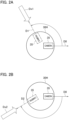
FIG. 2A is a diagram obtained by looking down on a robot from directly above and is a diagram illustrating the rotation of ahead 30H of the robot from direction D0 to direction D1. -
FIG. 2B is a diagram obtained by looking down on a robot from directly above and is a diagram illustrating the rotation of ahead 30H of the robot from direction D0 to direction D2. -
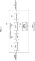
FIG. 3 is a block diagram illustrating a specific configuration example of a video signal processor of a remote controlled device according to a first embodiment. -
FIG. 4 is a diagram illustrating an example of a video signal of 60 frames per second and a video signal having a frame video update rate of 20 frames per second. -
FIG. 5 is a diagram illustrating an example of a video signal of 60 frames per second and a video signal having a frame video update rate of 20 frames per second and 10 frames per second. -
FIG. 6 is a block diagram illustrating a specific configuration example of a video signal processor and a controller of a remote controlled device according to a second embodiment. -
FIG. 7 is a block diagram illustrating a specific configuration example of an image display unit of an image display device according to a second embodiment. - Hereafter, a remote controlled device, an image display device, and a video display control method according to each embodiment will be described with reference to the accompanying drawings. First, a configuration example of a remote control system having the image display device and the remote controlled device will be explained with reference to
FIG. 1 . - In
FIG. 1 , animage display device 10 and arobot 30 are connected to each other via anetwork 20. Therobot 30 is located at a remote location away from where theimage display device 10 is located. Theimage display device 10 is a head-mounted display as an example. Therobot 30 is an example of a remote controlled device of which the movement is controlled in accordance with movement data indicating the movement of theimage display device 10 or a user wearing theimage display device 10. Thenetwork 20 is typically the Internet. - The
image display device 10 includes animage display unit 11, amovement sensor 12, aspeaker 13, and anetwork communication unit 14. Themovement sensor 12 includes an acceleration sensor and a gyro-sensor to detect acceleration and angular velocity indicating a change in rotation or orientation when the image display device 10 (that is, the user) moves. Thespeaker 13 includes headphones or earphones. - When the user wearing the
image display device 10 moves, movement data indicating the user's movement detected by means of themovement sensor 12 is encoded. Then the encoded data is transmitted to therobot 30 via thenetwork communication unit 14 and thenetwork 20. Thenetwork communication unit 14 functions as a transmission unit. - The
robot 30 includes acontroller 31, adriver 32, a movingunit 33, anetwork communication unit 34, acamera 35, avideo signal processor 36,microphones 37a to 37d, and rangingsensors 38a to 38d. Thecontroller 31 can be formed of a microcomputer or a microprocessor. - After the
network communication unit 34 receives the movement data transmitted from theimage display device 10, thenetwork communication unit 34 supplies the movement data to thecontroller 31. Thenetwork communication unit 34 functions as a receiving unit. Thecontroller 31 decodes the encoded movement data and controls thedriver 32 to move the movingunit 33 in accordance with the movement data. Themoving unit 33 is constituted by the head, legs, and the like of therobot 30, for example. Thedriver 32 includes an actuator that is at least one of an electric motor, an electromagnetic solenoid, a hydraulic cylinder, and a pneumatic cylinder for rotating the head or moving the legs. Thedriver 32 drives the actuator based on control performed by thecontroller 31. - The moving
unit 33 of therobot 30 moves in accordance with movement data transmitted from theimage display device 10. Therefore, therobot 30 moves so as to follow the user's movement. - The
camera 35 is attached to ahead 30H (seeFIG. 2A or FIG. 2B ) of therobot 30, for example. Thecamera 35 captures a range of a predetermined angle around therobot 30. Thecamera 35 may be a stereo camera. A video signal composed of digital data output from thecamera 35 is supplied to thevideo signal processor 36. Thevideo signal processor 36 compression-encodes the video signal and supplies the compression-encoded video data to thecontroller 31. Thenetwork communication unit 34 transmits the video data supplied from thecontroller 31 to theimage display device 10 via thenetwork 20. Thenetwork communication unit 34 functions as a transmission unit. - After the
network communication unit 14 receives the video data transmitted from therobot 30, thenetwork communication unit 14 supplies the video data to theimage display unit 11. Thenetwork communication unit 14 functions as a receiving unit. Theimage display unit 11 displays images based on a decoded video signal obtained by decoding the video data. The user views the images displayed on theimage display unit 11. - The
robot 30 may encode audio signals collected by means of themicrophones 37a to 37d and transmit the encoded audio data to theimage display device 10. Themicrophones 37a to 37d are arranged at 90-degree intervals in line in the circumferential direction of therobot 30, for example. After theimage display device 10 receives the audio data, thespeaker 13 outputs audio based on the decoded audio signal obtained by decoding the audio data by means of an audio decoder (not shown). - In the remote control system in which the
image display device 10 and therobot 30 are connected via thenetwork 20, the image display device 10 (the user) controls therobot 30 in real time. Therobot 30 moves in accordance with movement data indicating the user's movement. Theimage display device 10 receives the video captured by therobot 30 or the sound collected by therobot 30 in addition to the video. - To prevent the
robot 30 from failing due to some kind of object hitting therobot 30, therobot 30 is configured to take a risk-avoidance action itself, for example. Therobot 30 has the rangingsensors 38a to 38d. The rangingsensors 38a to 38d are arranged at 90-degree intervals in line in the circumferential direction of therobot 30, for example. Thecontroller 31 detects whether there is an object approaching therobot 30 and the approaching direction based on the sound collected by means of themicrophones 37a to 37d and the distance between the robot and the object measured by means of the rangingsensors 38a to 38d. Thecontroller 31 determines that an object is approaching based on the detected results. - The
controller 31 may detect whether there is an object approaching therobot 30 and the approaching direction based only on the distance between the robot and the object measured by means of the rangingsensors 38a to 38d. - As shown in
FIG. 2A , thehead 30H of therobot 30 is oriented such that the center of the imaging range of thecamera 35 is aligned with the direction D0. Assume that thecontroller 31 determines that the object is approaching from the direction Dx1, which is a blind spot of thecamera 35. The direction in which the object approaches at this time is another direction different from the direction in which thecamera 35 captures video. At this time, thecontroller 31 controls thedriver 32 to rotate thehead 30H such that the center of the imaging range of thecamera 35 is aligned with the direction D1 in order to check the object. After thecamera 35 captures the object, the user can control therobot 30 to drive the legs of therobot 30 so that therobot 30 can take a risk-avoidance action. In addition, thecontroller 31 may control thedriver 32 to drive the legs so that therobot 30 itself takes a risk-avoidance action. -
FIG. 2B shows the case where thecontroller 31 detects the approach of an object from the direction Dx2, which is a blind spot of thecamera 35 and is approximately behind the direction D0. The direction in which the object approaches at this time is another direction different from the direction in which thecamera 35 captures video. In this case also, thecontroller 31 controls thedriver 32 to rotate thehead 30H such that the center of the imaging range of thecamera 35 is aligned with the direction D2 in order to check the object. - Suppose that the
robot 30 itself rotates itshead 30H in order to take a risk-avoidance action. In the above case, the video signal (the video data) transmitted to theimage display device 10 moves rapidly regardless of the user's intention even when the user is stationary. Accordingly, the user may experience visually induced motion sickness and confusion. Therefore, theimage display device 10 and therobot 30 are configured as in the following first or second embodiment. - In a first embodiment, the
video signal processor 36 in therobot 30 is configured as follows in order to mitigate the visually induced motion sickness and confusion experienced by the user. As shown inFIG. 3 , thevideo signal processor 36 includes awrite controller 361, astorage unit 362, aread controller 363, aframe update controller 364, and anencoder 365. - The
write controller 361 writes the video signal of 60 frames per second output from thecamera 35 into thestorage unit 362, for example. In a state in which therobot 30 moves to follow the user's movement, theframe update controller 364 controls theread controller 363 such that the video signal stored in thestorage unit 362 is read at 60 frames per second. Therefore, theread controller 363 reads the video signal stored in thestorage unit 362 at 60 frames per second. Theencoder 365 compression-encodes the read video signal of 60 frames per second and supplies the compression-encoded video data to thecontroller 31. - At this time, the frame video update rate of the video signal of 60 frames per second transmitted to the
image display device 10 is a first rate. Frame videos are videos in units of frames. - The
controller 31 controls thedriver 32 such that therobot 30 itself rotates thehead 30H as shown inFIG. 2A or FIG. 2B in order to take a risk-avoidance action. At this time, theframe update controller 364 controls theread controller 363 to read the video signal stored in thestorage unit 362 at a rate lower than 60 frames per second. Theframe update controller 364 controls theread controller 363 to read the video signal stored in thestorage unit 362 at a rate corresponding to 20 frames per second. Theencoder 365 compression-encodes the read video signal having a rate corresponding to 20 frames per second and supplies the compression-encoded video data to thecontroller 31. - At this time, the frame video update rate of the video signal transmitted to the
image display device 10 is a second rate which is lower than the first rate. A video signal of the second rate is generated based on the video signal of the first rate. - The
controller 31 can obtain the time required for rotating thehead 30H such that the center of the imaging range of thecamera 35 is aligned with the direction D1 or D2. Therefore, thecontroller 31 instructs theframe update controller 364 to read the signal at a rate lower than 60 frames per second during the time from the start of rotation of thehead 30H until the center of the imaging range of thecamera 35 is aligned with the direction D1 or D2. - (a) of
FIG. 4 shows frame videos F1, F2, F3, F4 and so forth of 60 frames per second input to thevideo signal processor 36. Theframe update controller 364 controls theread controller 363 to update a frame video read out once every three frames out of the frame videos stored in thestorage unit 362. As a result, as shown in (b) ofFIG. 4 , the frame video update rate is 20 frames per second, as in the case of frame videos F1, F1, F1, F4, F4, F4, F5, and so forth. The compression-encoded video data of substantially 20 frames per second is output from thevideo signal processor 36. - Strictly speaking, the video data shown in (b) of
FIG. 4 is a video signal of 60 frames per second. However, since the frame video update rate is 20 frames per second, the video signal seemingly corresponds to a video signal of 20 frames per second. Since video data having a rate corresponding to 20 frames per second is transmitted to theimage display device 10, the video does not move rapidly and it is possible to reduce the visually induced motion sickness and confusion experienced by the user. - In (b) of
FIG. 4 , theframe update controller 364 controls the reading of the frame videos from thestorage unit 362 and reduces the frame video update rate. As shown in (c) ofFIG. 4 , thevideo signal processor 36 may actually control the frame rate to be 20 frames per second. It is also possible to set the rate at which the frame videos read from thestorage unit 362 are updated to 20 frames per second by reducing the frame videos to be written in thestorage unit 362. - In
FIG. 2B , the angle at which thehead 30H is rotated is larger than that inFIG. 2A . Thecontroller 31 may increase the rotation speed as the angle at which thehead 30H is rotated increases. Correspondingly, thecontroller 31 may lower the rate at which the frame videos are updated as the rotation speed increases. - (a) of
FIG. 5 shows frame videos F1, F2, F3, F4 and so forth of 60 frames per second output by thevideo signal processor 36. (b) ofFIG. 5 shows the frame video update rate when the angle at which thehead 30H is rotated is relatively small as shown inFIG. 2A and the rotation speed is relatively slow. As in (b) ofFIG. 4 , the frame video update rate is 20 frames per second. - (c) of
FIG. 5 shows the frame video update rate when the angle at which thehead 30H is rotated is large as shown inFIG. 2B and the rotation speed is high. In (c) ofFIG. 5 , the frame video update rate is set to be 10 frames per second. Even if thehead 30H is rotated rapidly by means of thecontroller 31, video data having a rate corresponding to 10 frames per second is transmitted to theimage display device 10. Therefore, the video does not move rapidly and it is possible to reduce the visually induced motion sickness and confusion experienced by the user. - The
controller 31 may gradually increase the frame video update rate immediately before stopping the rotation of thehead 30H, and gradually return the rate to 60 frames per second. - In a second embodiment, the
video signal processor 36 in therobot 30 and theimage display unit 11 in theimage display device 10 are configured as follows in order to reduce the visually induced motion sickness and confusion experienced by the user. - As shown in
FIG. 6 , thevideo signal processor 36 includes thewrite controller 361, thestorage unit 362, theread controller 363, and theencoder 365. Thecontroller 31 includes an additionaldata superimposing unit 311 that superimposes additional data on the compression-encoded video data output from theencoder 365. The rate of video data output from thevideo signal processor 36 is 60 frames per second. When thecontroller 31 causes therobot 30 itself to rotate thehead 30H in order to take a risk-avoidance action, the additionaldata superimposing unit 311 superimposes additional data on the video data, the additional data being for identifying the start and end of the period during which thehead 30H is rotated. - The additional data may include additional data indicating the timing of the start of the period during which the
head 30H is rotated and additional data indicating the timing of the end of the period. Further, the additional data may include additional data indicating the timing of the start of the period during which thehead 30H is rotated and additional data indicating the time during which the head is rotated. Suppose that thecontroller 31 increases the rotation speed as the angle at which thehead 30H is rotated increases. In the above case, the additional data may include additional data indicating at least two levels of rotation speed. - In this way, when the
robot 30 itself rotates thehead 30H in order to take a risk-avoidance action, therobot 30 transmits video data on which additional data is superimposed to theimage display device 10. - As shown in
FIG. 7 , theimage display unit 11 includes adecoder 111, awrite controller 112, astorage unit 113, aread controller 114, aframe update controller 115, and adisplay panel 116. Thedecoder 111 decodes the video data transmitted from therobot 30. Thewrite controller 112 writes the decoded video signal of 60 frames per second into thestorage unit 113. Decoded additional data is input to theframe update controller 115. - If no additional data is input to the
frame update controller 115, theframe update controller 115 controls theread controller 114 to read the video signal stored in thestorage unit 113 at 60 frames per second. In the video signal of 60 frames per second supplied to thedisplay panel 116, the frame video update rate is the first rate. - If additional data is input to the
frame update controller 115, theframe update controller 115 controls theread controller 114 to read the video signal stored in thestorage unit 113 such that the frame video update rate becomes lower than 60 frames per second from the start to the end of the period during which thehead 30H is rotated. - As in the first embodiment, the
frame update controller 115 controls theread controller 114 to update a frame video read out once every three frames out of the frame videos stored in thestorage unit 113. As a result, the rate at which the frame videos of the video signal displayed on thedisplay panel 116 are updated is 20 frames per second, as in the case of the frame videos F1, F1, F1, F4, F4, F4, F5 and so forth as in (b) ofFIG. 4 . - The rate at which the frame videos of the video signal supplied to the
display panel 116 are updated is the second rate which is lower than the first rate. The video signal of the second rate is generated based on the video signal of the first rate. - Suppose that the additional data includes information indicating the level of the rotation speed. In the above case, the
frame update controller 115 may control theread controller 114 such that the frame video update rate decreases as the rotation speed increases. - In the second embodiment, the
robot 30 transmits video data of 60 frames per second to theimage display device 10. Suppose that therobot 30 itself rotates thehead 30H in order to take a risk-avoidance action. In the above case, thedisplay panel 116 of theimage display device 10 displays a video signal in which the frame video update rate is 20 frames per second or 10 frames per second. Accordingly, in the second embodiment also, the video does not move rapidly and it is possible to reduce the visually induced motion sickness and confusion experienced by the user. - In the second embodiment also, it is preferable to gradually increase the frame video update rate immediately before stopping the rotation of the
head 30H, and to gradually return the rate to 60 frames per second. - When the user moves his or her face up and down to move the line of sight up and down, instead of updating the rate of the frame videos, the
image display unit 11 may display images as follows. Theimage display unit 11 cuts out an overlapping area in the up-and-down direction between the image before moving and the image after moving, and displays images without blurring in the up-down direction by enlarging the images as needed. - In order to reduce the visually induced motion sickness and confusion experienced by the user, the
robot 30 may be configured as follows. When thecontroller 31 controls thedriver 32 so as to move the movingunit 33 in accordance with the movement data, thecontroller 31 controls thevideo signal processor 36 to generate frame videos having a first resolution, which is the normal resolution. When thecontroller 31 controls thedriver 32 so as to move the movingunit 33 regardless of the movement data, thecontroller 31 controls thevideo signal processor 36 to generate frame videos having a second resolution which is lower than the first resolution. In order to make the frame videos having the first resolution into the frame videos having the second resolution, it is sufficient if thevideo signal processor 36 reduces the number of pixels in the horizontal direction and reduces the number of lines in the vertical direction. - In order to reduce the visually induced motion sickness and confusion experienced by the user, the
image display device 10 may be configured as follows. If no additional data is input, theimage display unit 11 displays the video signal received by thenetwork communication unit 14 as frame videos having the first resolution. If additional data is input, theimage display unit 11 displays the video signal received by thenetwork communication unit 14 as frame videos having the second resolution. Theimage display unit 11 may reduce the number of pixels in the horizontal direction and reduce the number of lines in the vertical direction in order to make the frame videos having the first resolution into the frame videos having the second resolution. - In order to reduce the visually induced motion sickness and confusion experienced by the user, the
robot 30 may be configured as follows. When thecontroller 31 controls thedriver 32 to move the movingunit 33 in accordance with the movement data, thecontroller 31 controls thevideo signal processor 36 to generate normal frame videos on which blurring processing is not performed. When thecontroller 31 controls thedriver 32 to move the movingunit 33 regardless of the movement data, thecontroller 31 controls thevideo signal processor 36 to generate blurred frame videos obtained by performing the blurring processing on the frame videos. Thevideo signal processor 36 removes the high-frequency component of the frame videos by means of a low-pass filter in order to perform the blurring processing on the frame videos, for example. There are no restrictions on how the blurring processing is performed. - In order to reduce the visually induced motion sickness and confusion experienced by the user, the
image display device 10 may be configured as follows. When no additional data is input, theimage display unit 11 displays a video signal, on which the blurring processing is not performed, received by thenetwork communication unit 14 as frame videos without any changes. When additional data is input, theimage display unit 11 performs the blurring processing on the video signal received by thenetwork communication unit 14 and displays the signal as blurred frame videos. Theimage display unit 11 removes the high-frequency component of the video signal received by thenetwork communication unit 14 by means of a low-pass filter, for example. There are no restrictions on how the blurring processing is performed. - As described above, when the
controller 31 of therobot 30 controls thedriver 32 so as to move the movingunit 33 in accordance with the movement data, thecontroller 31 generates video data formed of frame videos having a first display mode. When thecontroller 31 controls thedriver 32 so as to move the movingunit 33 regardless of the movement data, thecontroller 31 generates video data formed of frame videos having a second display mode different from the first display mode. If no additional data is input, theimage display unit 11 of theimage display device 10 displays the frame videos having the first display mode. If additional data is input, theimage display unit 11 displays the frame videos having the second display mode different from the first display mode. - The frame videos having the second display mode are frame videos that give less stimulus to the user than the frame videos having the first display mode. As described above, the first display mode may differ from the second display mode in terms of the frame rate, the resolution, and whether the blurring processing is performed. Any combination of the frame rate change, the resolution change, and whether the blurring processing is performed may be used.
- The present invention is not limited to the first to sixth embodiments described above, and various modifications are possible within a scope not departing from the scope of the present invention.
- The present application claims priority based on
Japanese Patent Application No. 2021-048618, filed with the Japan Patent Office on March 23, 2021
Claims (12)
- A remote controlled device comprising:a moving unit;a driver configured to drive the moving unit;a network communication unit configured to receive movement data indicating a movement of a user via a network and to transmit video data to an image display device worn by the user;a controller configured to control the driver so as to move the moving unit in accordance with the movement data;a camera attached to the moving unit; anda video signal processor configured to generate the video data based on a video signal captured by the camera, whereinthe controller controls the video signal processor such that when the controller controls the driver so as to move the moving unit in accordance with the movement data, the controller generates video data formed of a frame video having a first display mode, and when the controller controls the driver so as to move the moving unit regardless of the movement data, the controller generates video data formed of a frame video having a second display mode.
- The remote controlled device according to claim 1, wherein
the controller generates video data formed of a frame video that is updated at a first rate, as the frame video having the first display mode, and video data formed of a frame video that is updated at a second rate lower than the first rate, as the frame video having the second display mode. - The remote controlled device according to claim 1, wherein
the controller generates video data formed of a frame video having a first resolution, as the frame video having the first display mode, and video data formed of a frame video having a second resolution lower than the first resolution, as the frame video having the second display mode. - The remote controlled device according to claim 1, wherein
the controller generates video data formed of a frame video on which blurring processing is not performed, as the frame video having the first display mode, and video data formed of a frame video on which blurring processing is performed, as the frame video having the second display mode. - The remote controlled device according to any one of claims 1 to 4, comprising:a plurality of ranging sensors arranged in line in a circumferential direction of the remote controlled device and configured to measure a distance between the remote controlled device and another object, whereinwhen the controller determines that the other object is approaching the remote controlled device from another direction different from a direction in which the camera is capturing images, based on the distance measured by means of the plurality of ranging sensors, the controller controls the driver so as to move the moving unit regardless of the movement data.
- The remote controlled device according to claim 2, wherein
the video signal processor comprises:a storage unit configured to store the video signal that has the first rate and is captured by the camera;a read controller configured to read the video signal from the storage unit; anda frame update controller configured to control the read controller to set a rate at which a frame video is updated, to the second rate when the controller controls the driver so as to move the moving unit regardless of the movement of the user. - An image display device comprising:a movement sensor configured to detect a movement of a user;a receiving unit configured to receive a video signal and additional data, the video signal being captured by a camera attached to a moving unit of a remote controlled device configured to move in accordance with movement data indicating the movement of the user detected by the movement sensor, and the additional data being for identifying a start and an end of a period during which the moving unit is rotated; andan image display unit configured to display the video signal received by the receiving unit, whereinthe additional data is superimposed on the video signal when the remote controlled device moves the moving unit regardless of the movement data, andwhen the additional data is not input, the image display unit displays the video signal received by the receiving unit as a frame video having a first display mode, and when the additional data is input, the image display unit displays the video signal received by the receiving unit as a frame video having a second display mode.
- The image display device according to claim 7, wherein
the image display unit displays a frame video that is updated at a first rate as the frame video having the first display mode, and displays a frame video that is updated at a second rate lower than the first rate as the frame video having the second display mode. - The image display device according to claim 7, wherein
the image display unit displays a frame video having a first resolution as the frame video having the first display mode, and displays a frame video having a second resolution lower than the first resolution as the frame video having the second display mode. - The image display device according to claim 7, wherein
the image display unit displays a frame video to which blurring processing is not performed as the frame video having the first display mode, and displays a frame video to which blurring processing is performed as the frame video having the second display mode. - The image display device according to claim 8, wherein
the image display unit comprises:a storage unit configured to store the video signal that has the first rate and is received by the receiving unit;a read controller configured to read the video signal from the storage unit; anda frame update controller configured to control the read controller to set a rate at which a frame video is updated, to the second rate when the remote controlled device moves the moving unit regardless of the movement of the user. - A video display control method comprising:transmitting movement data indicating a movement of a user to a remote controlled device;moving a moving unit in accordance with the received movement data by means of the remote controlled device;transmitting a video signal captured by a camera attached to the moving unit to an image display device worn by the user by means of the remote controlled device;displaying the video signal transmitted from the remote controlled device by means of an image display unit of the image display device;displaying a video signal of which a first rate is a rate at which a frame video is updated by means of the image display unit when a controller of the remote controlled device moves the moving unit in accordance with the movement data; andwhen the controller moves the moving unit regardless of the movement of the user, transmitting a video signal formed of a frame video having a second display mode different from a first display mode, to the image display device by means of the remote controlled device, and displaying the video signal formed of the frame video having the second display mode by means of the image display unit, or transmitting a video signal formed of a frame video having the first display mode, to the image display device by means of the remote controlled device, and displaying a video signal formed of a frame video having the second display mode based on the frame video having the first display mode by means of the image display unit.
Applications Claiming Priority (2)
| Application Number | Priority Date | Filing Date | Title |
|---|---|---|---|
| JP2021048618 | 2021-03-23 | ||
| PCT/JP2021/047019 WO2022201683A1 (en) | 2021-03-23 | 2021-12-20 | Remotely controlled device, image display device, and video display control method |
Publications (3)
| Publication Number | Publication Date |
|---|---|
| EP4319145A1 true EP4319145A1 (en) | 2024-02-07 |
| EP4319145A4 EP4319145A4 (en) | 2024-09-25 |
| EP4319145B1 EP4319145B1 (en) | 2025-11-19 |
Family
ID=83396666
Family Applications (1)
| Application Number | Title | Priority Date | Filing Date |
|---|---|---|---|
| EP21931963.9A Active EP4319145B1 (en) | 2021-03-23 | 2021-12-20 | Remotely controlled device, image display device, and video display control method |
Country Status (5)
| Country | Link |
|---|---|
| US (1) | US12296491B2 (en) |
| EP (1) | EP4319145B1 (en) |
| JP (2) | JP7757976B2 (en) |
| CN (1) | CN115398887B (en) |
| WO (1) | WO2022201683A1 (en) |
Family Cites Families (13)
| Publication number | Priority date | Publication date | Assignee | Title |
|---|---|---|---|---|
| JPS6246636A (en) | 1985-08-26 | 1987-02-28 | 株式会社アイジー技術研究所 | Large-sized sandwich panel |
| JP5017646B2 (en) * | 2007-02-23 | 2012-09-05 | 国立大学法人長岡技術科学大学 | Video transmission system, video transmission apparatus, video transmission method, exploration robot, and program |
| JP2011152593A (en) * | 2010-01-26 | 2011-08-11 | Nec Corp | Robot operation device |
| EP2904481A4 (en) | 2012-10-01 | 2016-08-17 | Revolve Robotics Inc | Robotic stand and systems and methods for controlling the stand during videoconference |
| KR102465856B1 (en) | 2015-03-27 | 2022-11-11 | 한국전자통신연구원 | Apparatus for generating broadcasting signal frame using bboundary of core layer plps and method using the same |
| JP6641763B2 (en) * | 2015-08-03 | 2020-02-05 | セイコーエプソン株式会社 | Display system |
| US10564722B2 (en) * | 2015-11-20 | 2020-02-18 | Facebook Technologies, Llc | Restricting user movement via connecting tendons in a garment to a jamming mechanism |
| EP3500822A4 (en) * | 2016-08-18 | 2019-08-28 | SZ DJI Technology Co., Ltd. | SYSTEMS AND METHODS FOR INCREASED STEREOSCOPIC DISPLAY |
| EP3770549B1 (en) * | 2018-03-23 | 2022-09-21 | Sony Group Corporation | Information processing device, movement device, method, and program |
| KR102678682B1 (en) * | 2018-05-21 | 2024-06-25 | 텔레이그지스턴스 인크. | Remote control systems, information processing methods and programs |
| US11228737B2 (en) * | 2019-07-31 | 2022-01-18 | Ricoh Company, Ltd. | Output control apparatus, display terminal, remote control system, control method, and non-transitory computer-readable medium |
| JP6801136B1 (en) * | 2020-05-14 | 2020-12-16 | エヌ・ティ・ティ・コミュニケーションズ株式会社 | Remote control system and its remote work equipment, video processing equipment and programs |
| JP7332047B2 (en) * | 2020-06-01 | 2023-08-23 | 日本電気株式会社 | Tracking Devices, Tracking Systems, Tracking Methods, and Programs |
-
2021
- 2021-12-20 EP EP21931963.9A patent/EP4319145B1/en active Active
- 2021-12-20 WO PCT/JP2021/047019 patent/WO2022201683A1/en not_active Ceased
- 2021-12-20 CN CN202180021414.0A patent/CN115398887B/en active Active
- 2021-12-20 JP JP2022556667A patent/JP7757976B2/en active Active
-
2022
- 2022-09-29 US US17/955,942 patent/US12296491B2/en active Active
-
2025
- 2025-09-26 JP JP2025160472A patent/JP2025175202A/en active Pending
Also Published As
| Publication number | Publication date |
|---|---|
| JP2025175202A (en) | 2025-11-28 |
| CN115398887A (en) | 2022-11-25 |
| JPWO2022201683A1 (en) | 2022-09-29 |
| EP4319145A4 (en) | 2024-09-25 |
| US20230026805A1 (en) | 2023-01-26 |
| US12296491B2 (en) | 2025-05-13 |
| WO2022201683A1 (en) | 2022-09-29 |
| CN115398887B (en) | 2025-07-01 |
| JP7757976B2 (en) | 2025-10-22 |
| EP4319145B1 (en) | 2025-11-19 |
Similar Documents
| Publication | Publication Date | Title |
|---|---|---|
| WO2015003270A1 (en) | Telepresence method and system for supporting out of range motion | |
| CA2459446C (en) | Image compensation apparatus | |
| JP2020514900A5 (en) | ||
| JPH11133347A (en) | Video observation device | |
| US20170094261A1 (en) | Stereoscopic imaging | |
| JPWO2016047087A1 (en) | Automotive electronic mirror | |
| JP7247371B2 (en) | Image processing device, system, image processing method, and image processing program | |
| WO2019073925A1 (en) | Image generation device and image generation method | |
| JP2020145612A (en) | Image processing equipment, image processing system, image processing method, and program | |
| WO2018036112A1 (en) | Method and system for encoding/decoding panoramic video | |
| JP2011152593A (en) | Robot operation device | |
| CN105730335A (en) | 360-degree panoramic driving recorder and recording method thereof | |
| EP4319145B1 (en) | Remotely controlled device, image display device, and video display control method | |
| WO2015003268A1 (en) | Telepresence method and system for tracking head movement of a user | |
| JP2002174840A (en) | Preset monitoring device | |
| JP7406902B2 (en) | Control device, control method, program, method and storage medium | |
| EP3547663B1 (en) | Panaoramic vision system with parallax mitigation | |
| CN112753066B (en) | Video display control device, method, and program recording medium | |
| US20230071690A1 (en) | Remote control system, remote operation apparatus, video image processing apparatus, and computer-readable medium | |
| CN205356558U (en) | System is watched in remote control and make a video recording and hold and watch end thereof | |
| JP6230223B2 (en) | Display direction control system and display position control system | |
| JP2018005778A (en) | Image display device, image display system, and image display method | |
| JP2012019466A (en) | Imaging device, control device, control method and image transmission control program | |
| JP2012085125A (en) | Network camera system, server, control method of the same, and program | |
| JP2007134886A (en) | Video camera system and imaging noise elimination method |
Legal Events
| Date | Code | Title | Description |
|---|---|---|---|
| STAA | Information on the status of an ep patent application or granted ep patent |
Free format text: STATUS: THE INTERNATIONAL PUBLICATION HAS BEEN MADE |
|
| PUAI | Public reference made under article 153(3) epc to a published international application that has entered the european phase |
Free format text: ORIGINAL CODE: 0009012 |
|
| STAA | Information on the status of an ep patent application or granted ep patent |
Free format text: STATUS: REQUEST FOR EXAMINATION WAS MADE |
|
| 17P | Request for examination filed |
Effective date: 20220930 |
|
| AK | Designated contracting states |
Kind code of ref document: A1 Designated state(s): AL AT BE BG CH CY CZ DE DK EE ES FI FR GB GR HR HU IE IS IT LI LT LU LV MC MK MT NL NO PL PT RO RS SE SI SK SM TR |
|
| DAV | Request for validation of the european patent (deleted) | ||
| DAX | Request for extension of the european patent (deleted) | ||
| A4 | Supplementary search report drawn up and despatched |
Effective date: 20240826 |
|
| RIC1 | Information provided on ipc code assigned before grant |
Ipc: G09G 5/36 20060101ALI20240820BHEP Ipc: G09G 5/00 20060101ALI20240820BHEP Ipc: H04N 7/18 20060101AFI20240820BHEP |
|
| GRAP | Despatch of communication of intention to grant a patent |
Free format text: ORIGINAL CODE: EPIDOSNIGR1 |
|
| STAA | Information on the status of an ep patent application or granted ep patent |
Free format text: STATUS: GRANT OF PATENT IS INTENDED |
|
| INTG | Intention to grant announced |
Effective date: 20250610 |
|
| GRAJ | Information related to disapproval of communication of intention to grant by the applicant or resumption of examination proceedings by the epo deleted |
Free format text: ORIGINAL CODE: EPIDOSDIGR1 |
|
| GRAP | Despatch of communication of intention to grant a patent |
Free format text: ORIGINAL CODE: EPIDOSNIGR1 |
|
| GRAS | Grant fee paid |
Free format text: ORIGINAL CODE: EPIDOSNIGR3 |
|
| INTG | Intention to grant announced |
Effective date: 20250911 |
|
| GRAA | (expected) grant |
Free format text: ORIGINAL CODE: 0009210 |
|
| STAA | Information on the status of an ep patent application or granted ep patent |
Free format text: STATUS: THE PATENT HAS BEEN GRANTED |
|
| AK | Designated contracting states |
Kind code of ref document: B1 Designated state(s): AL AT BE BG CH CY CZ DE DK EE ES FI FR GB GR HR HU IE IS IT LI LT LU LV MC MK MT NL NO PL PT RO RS SE SI SK SM TR |
|
| RAP3 | Party data changed (applicant data changed or rights of an application transferred) |
Owner name: JVCKENWOOD CORPORATION |
|
| REG | Reference to a national code |
Ref country code: CH Ref legal event code: F10 Free format text: ST27 STATUS EVENT CODE: U-0-0-F10-F00 (AS PROVIDED BY THE NATIONAL OFFICE) Effective date: 20251119 Ref country code: GB Ref legal event code: FG4D |
|
| REG | Reference to a national code |
Ref country code: DE Ref legal event code: R096 Ref document number: 602021042865 Country of ref document: DE |
|
| REG | Reference to a national code |
Ref country code: IE Ref legal event code: FG4D |
|
| PGFP | Annual fee paid to national office [announced via postgrant information from national office to epo] |
Ref country code: AT Payment date: 20260113 Year of fee payment: 5 |
|
| REG | Reference to a national code |
Ref country code: NL Ref legal event code: MP Effective date: 20251119 |
|
| PG25 | Lapsed in a contracting state [announced via postgrant information from national office to epo] |
Ref country code: ES Free format text: LAPSE BECAUSE OF FAILURE TO SUBMIT A TRANSLATION OF THE DESCRIPTION OR TO PAY THE FEE WITHIN THE PRESCRIBED TIME-LIMIT Effective date: 20251119 |
|
| REG | Reference to a national code |
Ref country code: LT Ref legal event code: MG9D |
|
| PG25 | Lapsed in a contracting state [announced via postgrant information from national office to epo] |
Ref country code: NO Free format text: LAPSE BECAUSE OF FAILURE TO SUBMIT A TRANSLATION OF THE DESCRIPTION OR TO PAY THE FEE WITHIN THE PRESCRIBED TIME-LIMIT Effective date: 20260219 |
|
| PGFP | Annual fee paid to national office [announced via postgrant information from national office to epo] |
Ref country code: DE Payment date: 20251224 Year of fee payment: 5 |
|
| PG25 | Lapsed in a contracting state [announced via postgrant information from national office to epo] |
Ref country code: FI Free format text: LAPSE BECAUSE OF FAILURE TO SUBMIT A TRANSLATION OF THE DESCRIPTION OR TO PAY THE FEE WITHIN THE PRESCRIBED TIME-LIMIT Effective date: 20251119 Ref country code: AT Free format text: LAPSE BECAUSE OF FAILURE TO SUBMIT A TRANSLATION OF THE DESCRIPTION OR TO PAY THE FEE WITHIN THE PRESCRIBED TIME-LIMIT Effective date: 20251119 Ref country code: HR Free format text: LAPSE BECAUSE OF FAILURE TO SUBMIT A TRANSLATION OF THE DESCRIPTION OR TO PAY THE FEE WITHIN THE PRESCRIBED TIME-LIMIT Effective date: 20251119 |
|
| REG | Reference to a national code |
Ref country code: AT Ref legal event code: MK05 Ref document number: 1859893 Country of ref document: AT Kind code of ref document: T Effective date: 20251119 |
|
| PG25 | Lapsed in a contracting state [announced via postgrant information from national office to epo] |
Ref country code: NL Free format text: LAPSE BECAUSE OF FAILURE TO SUBMIT A TRANSLATION OF THE DESCRIPTION OR TO PAY THE FEE WITHIN THE PRESCRIBED TIME-LIMIT Effective date: 20251119 |
|
| PG25 | Lapsed in a contracting state [announced via postgrant information from national office to epo] |
Ref country code: RS Free format text: LAPSE BECAUSE OF FAILURE TO SUBMIT A TRANSLATION OF THE DESCRIPTION OR TO PAY THE FEE WITHIN THE PRESCRIBED TIME-LIMIT Effective date: 20260219 |
|
| PG25 | Lapsed in a contracting state [announced via postgrant information from national office to epo] |
Ref country code: IS Free format text: LAPSE BECAUSE OF FAILURE TO SUBMIT A TRANSLATION OF THE DESCRIPTION OR TO PAY THE FEE WITHIN THE PRESCRIBED TIME-LIMIT Effective date: 20260319 |
|
| PG25 | Lapsed in a contracting state [announced via postgrant information from national office to epo] |
Ref country code: PT Free format text: LAPSE BECAUSE OF FAILURE TO SUBMIT A TRANSLATION OF THE DESCRIPTION OR TO PAY THE FEE WITHIN THE PRESCRIBED TIME-LIMIT Effective date: 20260319 |
|
| PG25 | Lapsed in a contracting state [announced via postgrant information from national office to epo] |
Ref country code: PL Free format text: LAPSE BECAUSE OF FAILURE TO SUBMIT A TRANSLATION OF THE DESCRIPTION OR TO PAY THE FEE WITHIN THE PRESCRIBED TIME-LIMIT Effective date: 20251119 |
|
| PG25 | Lapsed in a contracting state [announced via postgrant information from national office to epo] |
Ref country code: LV Free format text: LAPSE BECAUSE OF FAILURE TO SUBMIT A TRANSLATION OF THE DESCRIPTION OR TO PAY THE FEE WITHIN THE PRESCRIBED TIME-LIMIT Effective date: 20251119 |
|
| PG25 | Lapsed in a contracting state [announced via postgrant information from national office to epo] |
Ref country code: BG Free format text: LAPSE BECAUSE OF FAILURE TO SUBMIT A TRANSLATION OF THE DESCRIPTION OR TO PAY THE FEE WITHIN THE PRESCRIBED TIME-LIMIT Effective date: 20251119 |