EP4319005A1 - Verfahren und vorrichtung zur anzeige eines harq-prozesses in einem drahtloskommunikationssystem - Google Patents
Verfahren und vorrichtung zur anzeige eines harq-prozesses in einem drahtloskommunikationssystem Download PDFInfo
- Publication number
- EP4319005A1 EP4319005A1 EP22799014.0A EP22799014A EP4319005A1 EP 4319005 A1 EP4319005 A1 EP 4319005A1 EP 22799014 A EP22799014 A EP 22799014A EP 4319005 A1 EP4319005 A1 EP 4319005A1
- Authority
- EP
- European Patent Office
- Prior art keywords
- base station
- increased
- harq process
- harq
- satellite
- Prior art date
- Legal status (The legal status is an assumption and is not a legal conclusion. Google has not performed a legal analysis and makes no representation as to the accuracy of the status listed.)
- Pending
Links
Images


Classifications
-
- H—ELECTRICITY
- H04—ELECTRIC COMMUNICATION TECHNIQUE
- H04L—TRANSMISSION OF DIGITAL INFORMATION, e.g. TELEGRAPHIC COMMUNICATION
- H04L1/00—Arrangements for detecting or preventing errors in the information received
- H04L1/12—Arrangements for detecting or preventing errors in the information received by using return channel
- H04L1/16—Arrangements for detecting or preventing errors in the information received by using return channel in which the return channel carries supervisory signals, e.g. repetition request signals
- H04L1/18—Automatic repetition systems, e.g. Van Duuren systems
- H04L1/1825—Adaptation of specific ARQ protocol parameters according to transmission conditions
-
- H—ELECTRICITY
- H04—ELECTRIC COMMUNICATION TECHNIQUE
- H04L—TRANSMISSION OF DIGITAL INFORMATION, e.g. TELEGRAPHIC COMMUNICATION
- H04L5/00—Arrangements affording multiple use of the transmission path
- H04L5/003—Arrangements for allocating sub-channels of the transmission path
- H04L5/0053—Allocation of signalling, i.e. of overhead other than pilot signals
- H04L5/0055—Physical resource allocation for ACK/NACK
-
- H—ELECTRICITY
- H04—ELECTRIC COMMUNICATION TECHNIQUE
- H04L—TRANSMISSION OF DIGITAL INFORMATION, e.g. TELEGRAPHIC COMMUNICATION
- H04L1/00—Arrangements for detecting or preventing errors in the information received
- H04L1/12—Arrangements for detecting or preventing errors in the information received by using return channel
- H04L1/16—Arrangements for detecting or preventing errors in the information received by using return channel in which the return channel carries supervisory signals, e.g. repetition request signals
- H04L1/18—Automatic repetition systems, e.g. Van Duuren systems
- H04L1/1812—Hybrid protocols; Hybrid automatic repeat request [HARQ]
-
- H—ELECTRICITY
- H04—ELECTRIC COMMUNICATION TECHNIQUE
- H04B—TRANSMISSION
- H04B7/00—Radio transmission systems, i.e. using radiation field
- H04B7/14—Relay systems
- H04B7/15—Active relay systems
- H04B7/185—Space-based or airborne stations; Stations for satellite systems
- H04B7/1851—Systems using a satellite or space-based relay
- H04B7/18513—Transmission in a satellite or space-based system
-
- H—ELECTRICITY
- H04—ELECTRIC COMMUNICATION TECHNIQUE
- H04B—TRANSMISSION
- H04B7/00—Radio transmission systems, i.e. using radiation field
- H04B7/14—Relay systems
- H04B7/15—Active relay systems
- H04B7/185—Space-based or airborne stations; Stations for satellite systems
- H04B7/1853—Satellite systems for providing telephony service to a mobile station, i.e. mobile satellite service
-
- H—ELECTRICITY
- H04—ELECTRIC COMMUNICATION TECHNIQUE
- H04L—TRANSMISSION OF DIGITAL INFORMATION, e.g. TELEGRAPHIC COMMUNICATION
- H04L1/00—Arrangements for detecting or preventing errors in the information received
- H04L1/0001—Systems modifying transmission characteristics according to link quality, e.g. power backoff
- H04L1/0009—Systems modifying transmission characteristics according to link quality, e.g. power backoff by adapting the channel coding
-
- H—ELECTRICITY
- H04—ELECTRIC COMMUNICATION TECHNIQUE
- H04L—TRANSMISSION OF DIGITAL INFORMATION, e.g. TELEGRAPHIC COMMUNICATION
- H04L1/00—Arrangements for detecting or preventing errors in the information received
- H04L1/004—Arrangements for detecting or preventing errors in the information received by using forward error control
- H04L1/0056—Systems characterized by the type of code used
- H04L1/0061—Error detection codes
-
- H—ELECTRICITY
- H04—ELECTRIC COMMUNICATION TECHNIQUE
- H04L—TRANSMISSION OF DIGITAL INFORMATION, e.g. TELEGRAPHIC COMMUNICATION
- H04L1/00—Arrangements for detecting or preventing errors in the information received
- H04L1/12—Arrangements for detecting or preventing errors in the information received by using return channel
- H04L1/16—Arrangements for detecting or preventing errors in the information received by using return channel in which the return channel carries supervisory signals, e.g. repetition request signals
- H04L1/18—Automatic repetition systems, e.g. Van Duuren systems
- H04L1/1812—Hybrid protocols; Hybrid automatic repeat request [HARQ]
- H04L1/1819—Hybrid protocols; Hybrid automatic repeat request [HARQ] with retransmission of additional or different redundancy
-
- H—ELECTRICITY
- H04—ELECTRIC COMMUNICATION TECHNIQUE
- H04L—TRANSMISSION OF DIGITAL INFORMATION, e.g. TELEGRAPHIC COMMUNICATION
- H04L1/00—Arrangements for detecting or preventing errors in the information received
- H04L1/12—Arrangements for detecting or preventing errors in the information received by using return channel
- H04L1/16—Arrangements for detecting or preventing errors in the information received by using return channel in which the return channel carries supervisory signals, e.g. repetition request signals
- H04L1/18—Automatic repetition systems, e.g. Van Duuren systems
- H04L1/1829—Arrangements specially adapted for the receiver end
- H04L1/1835—Buffer management
- H04L1/1845—Combining techniques, e.g. code combining
-
- H—ELECTRICITY
- H04—ELECTRIC COMMUNICATION TECHNIQUE
- H04L—TRANSMISSION OF DIGITAL INFORMATION, e.g. TELEGRAPHIC COMMUNICATION
- H04L1/00—Arrangements for detecting or preventing errors in the information received
- H04L1/12—Arrangements for detecting or preventing errors in the information received by using return channel
- H04L1/16—Arrangements for detecting or preventing errors in the information received by using return channel in which the return channel carries supervisory signals, e.g. repetition request signals
- H04L1/18—Automatic repetition systems, e.g. Van Duuren systems
- H04L1/1829—Arrangements specially adapted for the receiver end
- H04L1/1854—Scheduling and prioritising arrangements
-
- H—ELECTRICITY
- H04—ELECTRIC COMMUNICATION TECHNIQUE
- H04L—TRANSMISSION OF DIGITAL INFORMATION, e.g. TELEGRAPHIC COMMUNICATION
- H04L1/00—Arrangements for detecting or preventing errors in the information received
- H04L1/12—Arrangements for detecting or preventing errors in the information received by using return channel
- H04L1/16—Arrangements for detecting or preventing errors in the information received by using return channel in which the return channel carries supervisory signals, e.g. repetition request signals
- H04L1/18—Automatic repetition systems, e.g. Van Duuren systems
- H04L1/1829—Arrangements specially adapted for the receiver end
- H04L1/1864—ARQ related signaling
-
- H—ELECTRICITY
- H04—ELECTRIC COMMUNICATION TECHNIQUE
- H04L—TRANSMISSION OF DIGITAL INFORMATION, e.g. TELEGRAPHIC COMMUNICATION
- H04L1/00—Arrangements for detecting or preventing errors in the information received
- H04L1/12—Arrangements for detecting or preventing errors in the information received by using return channel
- H04L1/16—Arrangements for detecting or preventing errors in the information received by using return channel in which the return channel carries supervisory signals, e.g. repetition request signals
- H04L1/18—Automatic repetition systems, e.g. Van Duuren systems
- H04L1/1867—Arrangements specially adapted for the transmitter end
- H04L1/1896—ARQ related signaling
-
- H—ELECTRICITY
- H04—ELECTRIC COMMUNICATION TECHNIQUE
- H04L—TRANSMISSION OF DIGITAL INFORMATION, e.g. TELEGRAPHIC COMMUNICATION
- H04L5/00—Arrangements affording multiple use of the transmission path
- H04L5/0001—Arrangements for dividing the transmission path
- H04L5/0003—Two-dimensional division
- H04L5/0005—Time-frequency
- H04L5/0007—Time-frequency the frequencies being orthogonal, e.g. OFDM(A) or DMT
-
- H—ELECTRICITY
- H04—ELECTRIC COMMUNICATION TECHNIQUE
- H04W—WIRELESS COMMUNICATION NETWORKS
- H04W56/00—Synchronisation arrangements
- H04W56/0005—Synchronisation arrangements synchronizing of arrival of multiple uplinks
-
- H—ELECTRICITY
- H04—ELECTRIC COMMUNICATION TECHNIQUE
- H04W—WIRELESS COMMUNICATION NETWORKS
- H04W56/00—Synchronisation arrangements
- H04W56/004—Synchronisation arrangements compensating for timing error of reception due to propagation delay
- H04W56/0045—Synchronisation arrangements compensating for timing error of reception due to propagation delay compensating for timing error by altering transmission time
-
- H—ELECTRICITY
- H04—ELECTRIC COMMUNICATION TECHNIQUE
- H04W—WIRELESS COMMUNICATION NETWORKS
- H04W72/00—Local resource management
- H04W72/12—Wireless traffic scheduling
- H04W72/1263—Mapping of traffic onto schedule, e.g. scheduled allocation or multiplexing of flows
-
- H—ELECTRICITY
- H04—ELECTRIC COMMUNICATION TECHNIQUE
- H04W—WIRELESS COMMUNICATION NETWORKS
- H04W72/00—Local resource management
- H04W72/12—Wireless traffic scheduling
- H04W72/1263—Mapping of traffic onto schedule, e.g. scheduled allocation or multiplexing of flows
- H04W72/1268—Mapping of traffic onto schedule, e.g. scheduled allocation or multiplexing of flows of uplink data flows
-
- H—ELECTRICITY
- H04—ELECTRIC COMMUNICATION TECHNIQUE
- H04W—WIRELESS COMMUNICATION NETWORKS
- H04W72/00—Local resource management
- H04W72/12—Wireless traffic scheduling
- H04W72/1263—Mapping of traffic onto schedule, e.g. scheduled allocation or multiplexing of flows
- H04W72/1273—Mapping of traffic onto schedule, e.g. scheduled allocation or multiplexing of flows of downlink data flows
-
- H—ELECTRICITY
- H04—ELECTRIC COMMUNICATION TECHNIQUE
- H04W—WIRELESS COMMUNICATION NETWORKS
- H04W72/00—Local resource management
- H04W72/20—Control channels or signalling for resource management
- H04W72/23—Control channels or signalling for resource management in the downlink direction of a wireless link, i.e. towards a terminal
-
- H—ELECTRICITY
- H04—ELECTRIC COMMUNICATION TECHNIQUE
- H04W—WIRELESS COMMUNICATION NETWORKS
- H04W72/00—Local resource management
- H04W72/50—Allocation or scheduling criteria for wireless resources
- H04W72/51—Allocation or scheduling criteria for wireless resources based on terminal or device properties
-
- H—ELECTRICITY
- H04—ELECTRIC COMMUNICATION TECHNIQUE
- H04W—WIRELESS COMMUNICATION NETWORKS
- H04W84/00—Network topologies
- H04W84/02—Hierarchically pre-organised networks, e.g. paging networks, cellular networks, WLAN [Wireless Local Area Network] or WLL [Wireless Local Loop]
- H04W84/04—Large scale networks; Deep hierarchical networks
- H04W84/06—Airborne or Satellite Networks
Definitions
- the disclosure relates to a method and device for configuring the number of hybrid automatic repeat request (HARQ) processes and indicating an identifier (ID) value in a wireless or mobile communication system.
- HARQ hybrid automatic repeat request
- ID an identifier
- the disclosure relates to a method and device for using downlink and uplink HARQ processes in an environment in which the number of HARQ processes is high or variable, for example, in case that a user equipment (LTE) performs signal transmission or reception with a base station via a satellite in a satellite communication system.
- LTE user equipment
- the 5G or pre-5G communication system is also called a “beyond 4G network” communication system or a "post LTE” system.
- the 5G communication system defined by 3GPP is called a "New Radio (NR) system”.
- the 5G communication system is considered to be implemented in ultrahigh frequency (mmWave) bands (e.g., 60GHz bands) so as to accomplish higher data rates.
- mmWave ultrahigh frequency
- FD-MIMO full dimensional MIMO
- array antenna analog beam forming, large scale antenna techniques have been discussed in 5G communication systems and applied to the NR system.
- cloud RANs cloud radio access networks
- D2D device-to-device
- wireless backhaul moving network
- CoMP coordinated multi-points
- FQAM FSK and QAM modulation
- SWSC sliding window superposition coding
- ACM advanced coding modulation
- FBMC filter bank multi carrier
- NOMA non-orthogonal multiple access
- SCMA sparse code multiple access
- the Internet which is a human centered connectivity network where humans generate and consume information
- IoT Internet of things
- IoE Internet of everything
- sensing technology “wired/wireless communication and network infrastructure”, “service interface technology”, and “security technology”
- M2M machine-to-machine
- MTC machine type communication
- IoT Internet technology
- IoT may be applied to a variety of fields including smart home, smart building, smart city, smart car or connected cars, smart grid, health care, smart appliances and advanced medical services through convergence and combination between existing information technology (IT) and various industrial applications.
- technologies such as a sensor network, machine type communication (MTC), and machine-to-machine (M2M) communication may be implemented by beamforming, MIMO, and array antennas.
- MTC machine type communication
- M2M machine-to-machine
- Application of a cloud radio access network (cloud RAN) as the above-described big data processing technology may also be considered an example of convergence of the 5G technology with the IoT technology.
- Satellite launching costs have been dramatically decreased in the late 2010s to 2020s and thus, there have been a lot of companies that desire to provide communication services via satellites. Accordingly, a satellite network is rising as a next generation network system that complements an existing terrestrial network. There may be possibility that the satellite network will not provide a terrestrial network level of user experience. However, it is advantageous that the satellite network is capable of providing a communication service in an area where a terrestrial network is difficult to be established or in a disaster situation. In addition, it is economical since, recently, the cost of satellite launching is dramatically decreased as described above. In addition, some companies and the 3rd generation partnership project (3GPP) standard are conducting research on direct communication between a UE (e.g., a smartphone) and a satellite.
- 3GPP 3rd generation partnership project
- a high propagation delay time may occur when electromagnetic waves arrive due to a long distance, such as a hundreds of km or thousands of km, or a longer, between the LTE and the satellite, and between the satellite and the base station on the ground.
- the propagation delay time between the UE and the satellite or the propagation delay time between the satellite and the base station in the satellite network is significantly higher than a propagation delay time that may occur when the UE and the base station directly communicate in the terrestrial network.
- the legacy LTE or NR system is designed to perform retransmission in case that initial data transmission fails in the physical layer so that a reception end combines received values of the data at the initial transmission and the retransmission, and decoding is performed.
- HARQ feedback and retransmission may be used.
- This is a scheme that combines a forward error correction (FEC) scheme that additionally sends a parity bit by using an error correction code so as to correct an error and an automatic repeat request (ARQ) scheme that retransmits transmitted data, and a receiver may identify whether received data has an error, and may request retransmission from a transmitter in case that an error is present.
- FEC forward error correction
- ARQ automatic repeat request
- an HARQ process may be defined and an index number may be assigned for each HARQ process. That is, other data may be mapped to HARQ processes having different indices numbers and may be transmitted.
- Transceivers may identify data by using the ID value of an HARQ process. In case that data is transmitted using any one HARQ process ID, a receiver may delete data transmitted previously using the same HARQ process ID from a memory (or a soft buffer) or may overwrite with new data, and may receive the new data.
- NTN non-terrestrial network
- information indicating whether data transmission performed once is successfully transmitted or fails may arrive at a transmitter from a receiver after dozens to hundreds of ms and thus, continuous data transmission may be difficult by only using 16 HARQ processes.
- a method implemented by a user equipment (UE) may include an operation of transmitting, to a base station, capability information indicating whether the UE supports the number of increased hybrid automatic repeat request (HARQ) processes, an operation of receiving information for configuring the number of increased HARQ processes from the base station in case that the UE supports the number of increased HARQ processes, and an operation of performing communication with the base station based on an HARQ process identifier (ID) in association with the number of increased HARQ processes configured based on the information.
- HARQ hybrid automatic repeat request
- a method implemented by a base station may include an operation of receiving, from a LTE, capability information indicating whether the LTE supports the number of increased hybrid automatic repeat request (HARQ) processes, an operation of transmitting information for configuring the number of increased HARQ processes to the LTE in case that the LTE supports the number of increased HARQ processes, and an operation of performing communication with the UE based on an HARQ process identifier (ID) in association with the number of increased HARQ processes configured based on the information.
- HARQ hybrid automatic repeat request
- a UE may include a transceiver configured to perform signal transmission or reception and a controller connected to the transceiver, and the controller is configured to transmit, to a base station, capability information associated with whether the UE supports the number of increased hybrid automatic repeat request (HARQ) processes, to receive, from the base station, information for configuring the number of increased HARQ processes in case that the UE supports the number of increased HARQ processes, and to perform communication with the base station based on an HARQ process identifier (ID) in association with the number of increased HARQ processes configured based on the information.
- HARQ hybrid automatic repeat request
- a base station may include a transceiver configured to perform signal transmission or reception and a controller connected to the transceiver, and the controller is configured to receive, from a LTE, capability information associated with whether the UE supports the number of increased hybrid automatic repeat request (HARQ) processes, to transmit information for configuring the number of increased HARQ processes in case that the UE supports the number of increased HARQ processes, and to perform communication with the UE based on an HARQ process identifier (ID) in association with the number of increased HARQ processes configured based on the information.
- HARQ hybrid automatic repeat request
- an HARQ process may be efficiently configured, indicated, and operated in the state in which a large number of HARQ processes are required.
- each block of the flowchart illustrations, and combinations of blocks in the flowchart illustrations can be implemented by computer program instructions.
- These computer program instructions can be provided to a processor of a general purpose computer, special purpose computer, or other programmable data processing apparatus to produce a machine, such that the instructions, which execute via the processor of the computer or other programmable data processing apparatus, create means for implementing the functions specified in the flowchart block or blocks.
- These computer program instructions may also be stored in a computer usable or computer-readable memory that can direct a computer or other programmable data processing apparatus to function in a particular manner, such that the instructions stored in the computer usable or computer-readable memory produce an article of manufacture including instruction means that implement the function specified in the flowchart block or blocks.
- the computer program instructions may also be loaded onto a computer or other programmable data processing apparatus to cause a series of operational steps to be performed on the computer or other programmable apparatus to produce a computer implemented process such that the instructions that execute on the computer or other programmable apparatus provide steps for implementing the functions specified in the flowchart block or blocks.
- each block of the flowchart illustrations may represent a module, segment, or portion of code, which includes one or more executable instructions for implementing the specified logical function(s). It should also be noted that in some alternative implementations, the functions noted in the blocks may occur out of the order. For example, two blocks shown in succession may in fact be executed substantially concurrently or the blocks may sometimes be executed in the reverse order, depending upon the functionality involved.
- the "unit” refers to a software element or a hardware element, such as a Field Programmable Gate Array (FPGA) or an Application Specific Integrated Circuit (ASIC), which performs a predetermined function.
- FPGA Field Programmable Gate Array
- ASIC Application Specific Integrated Circuit
- the "unit” does not always have a meaning limited to software or hardware.
- the “unit” may be constructed either to be stored in an addressable storage medium or to execute one or more processors. Therefore, the “unit” includes, for example, software elements, object-oriented software elements, class elements or task elements, processes, functions, properties, procedures, sub-routines, segments of a program code, drivers, firmware, micro-codes, circuits, data, database, data structures, tables, arrays, and parameters.
- the elements and functions provided by the "unit” may be either combined into a smaller number of elements, or a “unit”, or divided into a larger number of elements, or a “unit”. Moreover, the elements and “units” or may be implemented to reproduce one or more CPUs within a device or a security multimedia card.
- the new radio (NR) access technology which is a new 5G communication technology is designed to enable various services to be freely multiplexed in time and frequency resources. Accordingly, a waveform/numerology or the like and a reference signal or the like may be dynamically or freely allocated as a corresponding service is needed.
- a user equipment (UE) in wireless communication it is important to optimize data transmission by measuring the quality of a channel and the amount of interference. Accordingly, accurate measurement of a channel state is essential.
- unlike 4G communication in which channel and interference characteristics do not significantly change according to a frequency resource
- channel and interference characteristics significantly change according to a service.
- eMBB enhanced mobile broadband
- mMTC massive machine type communications
- URLLC ultra-reliable and low-latency communications
- eMBB is a service for high-speed transmission of large-capacity data.
- mMTC is a service for UE power minimization and multi-UE access.
- URLLC is a service for high reliability and low latency. Different requirements may be applied depending on the type of service applied to a UE.
- a plurality of services may be provided to a user in a communication system.
- a method and a device for providing services according to respective characteristics within the same time interval are desirable for a method and a device for providing services according to respective characteristics within the same time interval.
- a wireless communication system is evolving from the initial voice-based service to a broadband wireless communication system for providing high-speed and high-quality packet data services using communication standards, such as high-speed packet access (HSPA) of 3GPP, LTE ⁇ long-term evolution or evolved universal terrestrial radio access (E-UTRA) ⁇ , LTE-Advanced (LTE-A), LTE-Pro, high-rate packet data (HRPD) of 3GPP2, ultra-mobile broadband (UMB), IEEE 802.16e, and the like, as well as typical voice-based services.
- HSPA high-speed packet access
- E-UTRA evolved universal terrestrial radio access
- LTE-A LTE-Advanced
- LTE-Pro LTE-Pro
- HRPD high-rate packet data
- UMB ultra-mobile broadband
- IEEE 802.16e ultra-mobile broadband
- the NR system employs an orthogonal frequency division multiplexing (OFDM) scheme in a downlink (DL) and an uplink (UL). More specifically, the NR system employs a cyclic-prefix OFDM (CP-OFDM) scheme in a downlink and employs two schemes, that is, the CP-OFDM scheme and discrete Fourier transform spreading (DFT-S-OFDM) scheme in an uplink.
- the uplink indicates a radio link through which a user equipment (UE) or a mobile station (MS) transmits data or control signals to a base station (BS) or (gNode B), and the downlink indicates a radio link through which the base station transmits data or control signals to the UE.
- the above multiple access scheme separates data or control information of respective users by allocating and operating time-frequency resources for transmitting the data or control information for each user so as to avoid overlapping each other, that is, so as to establish orthogonality.
- the NR system employs a hybrid automatic repeat request (HARQ) scheme in which, when decoding is unsuccessful at the initial transmission, the corresponding data is retransmitted in a physical layer.
- HARQ hybrid automatic repeat request
- the receiver when a receiver fails to accurately decode data, the receiver transmits information (negative acknowledgement: NACK) informing a transmitter of the unsuccessful decoding and thus the transmitter may retransmit the corresponding data in the physical layer.
- NACK negative acknowledgement
- the receiver may increase data reception performance by combining the data retransmitted by the transmitter with the data the decoding of which has previously failed.
- the receiver transmits information (acknowledgement: ACK) informing the transmitter of the successful decoding and thus the transmitter may transmit new data.
- FIG. 1 is a diagram illustrating a basic structure of the time-frequency domain which is a radio resource area in which data or a control channel is transmitted in a downlink or an uplink of an NR system.
- the horizontal axis denotes the time domain
- the vertical axis denotes the frequency domain.
- the minimum transport unit in the time domain is an OFDM symbol, and Nsymb OFDM symbols 102 may be configured as a single slot 106.
- the length of a subframe is defined to be 1.0ms
- the length of a radio frame 114 is defined to be 10ms.
- the minimum transport unit in the frequency domain is a subcarrier.
- the entire system transmission bandwidth may include a total of N ⁇ BW subcarriers 104.
- One frame may be defined to be 10ms.
- One subframe may be defined to be 1ms and thus, one frame may include a total of 10 subframes.
- One subframe may include one or multiple slots, and the number of slots per one subframe may be different based on a set value ⁇ configured for a subcarrier spacing.
- N slot frame , ⁇ may also differ.
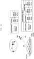
- N slot subframe , ⁇ and N slot frame , ⁇ based on a subcarrier spacing set value ⁇ may be defined as listed in Table 1 as below. [Table 1] ⁇ N symb slot N slot frame , ⁇ N slot subframe , ⁇ 0 14 10 1 1 14 20 2 2 14 40 4 3 14 80 8 4 14 160 16
- a user equipment (UE) before being radio resource control (RRC)-connected may receive, from a base station via a master information block (MIB), a configuration of an initial bandwidth part (initial BWP) for initial access. More specifically describing, at the initial access stage, the UE may receive configuration information associated with a search space and a control region (control resource set (CORESET)) in which a physical downlink control channel (PDCCH) is transmitted, in order to receive, via the MIB, system information (corresponding to remaining system information (RMSI) or system information block 1 (SIB1)) needed for initial access.
- CORESET control resource set
- PDCCH physical downlink control channel
- SIB1 system information block 1
- the base station may inform the LTE of configuration information such as frequency allocation information, time allocation information, numerology, or the like in association with control region #0, via the MIB.
- the base station may inform the LTE of configuration information related to a monitoring cycle and an occasion associated with control region #0, that is, configuration information associated with search space #0, via the MIB.
- the UE may consider, as an initial bandwidth part for initial access, a frequency range configured as control region #0 obtained from the MIB. In this instance, the identity (ID) of the initial bandwidth part may be considered as 0.
- the MIB may include information shown below.
- MIB field descriptions cell Barred Value barred means that the cell is barred, as defined in TS 38.304 [20].
- intraFreqReselection Controls cell selection/reselection to intra-frequency cells when the highest ranked cell is barred, or treated as barred by the UE, as specified in TS 38.304 [20].
- pdcch-ConfigSIB1 Determines a common ControlResourceSet (CORESET), a common search space and necessary PDCCH parameters.
- the field pdcch-ConfigSIB1 indicates the frequency positions where the UE may find SS/PBCH block with SIB1 or the frequency range where the network does not provide SS/PBCH block with SIB1 (see TS 38.21.3 [13], clause 13).
- ssb-SubcarrierOffset Corresponds to kSSS (see TS 38.213 [13]), which is the frequency domain offset between SSB and the overall resource block grid in number of subcarriers. (See TS 38.211 [16], clause 7.4.3.1).
- This field may be extended by an additional most significant bit encoded within PBCH as specified in TS 38.213 [13], This field may indicate that this cell does not provide SIB1 and that there is hence no CORESET#0 configured in MIB (see TS 38.213 [13], clause 13).
- the field pdcch-ConfigSIB1 may indicate the frequency positions where the UE may (not) find a SS/PBCH with a control resource set and search space for SIB1 (see TS 38.213 [13], clause 13).
- the value scs15or60 corresponds to 15 kHz and the value scs30or120 corresponds to 30 kHz. If the UE acquires this MIB on an FR2 carrier frequency, the value scs15or60 corresponds to 60 kHz and the value scs30or120 corresponds to 120 kHz systemFrameNumber
- MSB most significant bits
- SFN System Frame Number
- UEs before being RRC-connected may receive configuration information associated with an initial bandwidth part via an MIB in the initial access stage. More specifically describing, a LTE may receive, from an MIB of a physical broadcast channel (PBCH), a configuration of a control region for a downlink control channel in which a downlink control information (DCI) that schedules an SIB may be transmitted.
- PBCH physical broadcast channel
- DCI downlink control information
- the bandwidth of the control region configured via the MIB may be regarded as an initial bandwidth part
- the UE may receive, via the configured initial bandwidth part, a physical downlink shared channel (PDSCH) that transmits an SIB.
- the initial bandwidth part may be utilized for the purpose of other system information (OSI), paging, or random access.
- OSI system information
- a base station may indicate changing of a bandwidth part by using a bandwidth part indicator field in DCI.
- a basic resource unit in the time-frequency domain is a resource element (RE) 112, and an RE is expressed by an OFDM symbol index and a subcarrier index.
- a resource block (RB) 108 (or a physical resource block (PRB)) may be defined to be NRB consecutive subcarriers 110 in the frequency domain.
- the minimum transport unit of data is an RB.
- NBW is proportional to a system transmission bandwidth. The data rate may be increased in proportion to the number of RBs scheduled for a LTE.
- a downlink transmission bandwidth and an uplink transmission bandwidth may be different from each other in the case of an FDD system that operates a downlink and an uplink based on a frequency
- a channel bandwidth may be an RF bandwidth corresponding to a system transmission bandwidth.
- Table 2 and Table 3 show a part of the correspondence relationship of a system transmission bandwidth, a subcarrier spacing, and a channel bandwidth defined in the NR system, respectively in a frequency band lower than 6GHz and a frequency band higher than 6GHz.
- the transmission bandwidth may include 273 RBs.
- N/A in the following table may be a bandwidth-subcarrier combination that is not supported by the NR system.
- Table 2 shows the configuration of frequency range 1 (FR1) and Table 3 shows the configuration of FR2.
- SCS (kHz) 5MHz 10MHz 15MHz 20 MHz 25 MHz 30 MHz 40 MHz 50 MHz 60 MHz 80 MHz 90 MHz 100 MHz NRB NRB NRB NRB NRB NRB NRB NRB NRB NRB NRB NRB 15 25 52 79 106 133 160 216 270 N/A N/A N/A N/A 30 11 24 38 51 65 78 106 133 162 217 245 273 60 N/A 11 18 24 31 38 51 65 79 107 121 135
- Channel bandwidth BWChannel [MHz] subcarrier. width 50MHz 100MHz 200MHz 400 MHz Transmission bandwidth configuration NRB 60 kHz 66 132 264 N/A 120 kHz 32 66 132 264
- a frequency range may be separately defined as FR1 and FR2, as shown in Table 4 below.
- Table 4 Frequency range designation
- FR1 and FR2 may be changed to be different, and may be applied.
- the frequency range of FR1 may be changed to the range of 450MHz to 6000MHz and may be applied.
- SS synchronization signal
- PBCH block or SSB
- An SS/PBCH block may be a physical layer channel block including a primary SS (PSS), a secondary SS (SSS), and a PBCH. A detailed description thereof is provided as follow.
- PSS primary SS
- SSS secondary SS
- PBCH PBCH
- a UE may detect a PSS and an SSS, and may decode a PBCH.
- the UE may obtain an MIB from the PBCH, whereby control region #0 (corresponding to a control region having a control region index of 0) may be configured.
- control region #0 (corresponding to a control region having a control region index of 0) may be configured.
- the UE may assume that a selected SS/PBCH block and a demodulation reference signal (DMRS) transmitted in control region #0 are in a quasi co location (QCL), and may monitor control region #0.
- the UE may receive system information via downlink control information transmitted in control region #0. From the received system information, the UE may obtain random access channel (RACH)-related configuration information needed for initial access.
- RACH random access channel
- the UE may transmit a physical RACH to a base station in consideration of the selected SS/PBCH index, and the base station that receives the PRACH may obtain information associated with the index of the SS/PBCH block that the UE selects.
- the base station may recognize a block that the UE selects among SS/PBCH blocks and the fact that the UE monitors control region #0 related to the selected block.
- DCI downlink control information
- scheduling information for uplink data may be transferred from a base station to a LTE via DCI.
- the LTE may perform monitoring of a DCI format for fallback and a DCI format for non-fallback in association with a PUSCH or PDSCH.
- the fallback DCI format may be configured as a fixed field predefined between the base station and the UE, and the non-fallback DCI format may include a configurable field.
- various types of DCI formats may be used, and whether a corresponding DCI is for DCI for power control, DCI for notifying a slot format indicator (SFI), or the like may be indicated for each format.
- SFI slot format indicator
- the DCI may go through a channel coding a modulation process, and may be transmitted via a PDCCH that is a physical downlink control channel.
- a cyclic redundancy check (CRC) is added to a DCI message payload, and the CRC may be scrambled by a radio network temporary identifier (RNTI) corresponding to a UE identity.
- RNTI radio network temporary identifier
- Different RNTIs may be used depending on the purpose of a DCI message, for example, UE-specific data transmission, power control command, random access response, or the like. That is, an RNTI is not explicitly transmitted, but is transmitted by being included in a CRC calculation process.
- the UE may identify a CRC by using an allocated RNTI, and may recognize that the corresponding message is transmitted for the UE in case a CRC identification result is right.
- the PDCCH may be mapped to a control resource set (CORESET) configured for the UE, and may be transmitted.
- CORESET control resource set
- DCI that schedules a PDSCH associated with system information may be scrambled by an SI-RNTI.
- DCI that schedules a PDSCH associated with a random access response (RAR) message may be scrambled by an RA-RNTI.
- DCI that schedules a PDSCH associated with a paging message may be scrambled by a P-RNTI.
- DCI that reports a slot format indicator (SFI) may be scrambled by an SFI-RNTI.
- DCI that reports a transmit power control (TPC) may be scrambled by a TPC-RNTI.
- DCI that schedules a UE-specific PDSCH or PUSCH may be scrambled by a cell RNTI (C-RNTI).
- C-RNTI cell RNTI
- DCI format 0_0 may be used as a fallback DCI that schedules a PUSCH.
- a CRC may be scrambled by a C-RNTI.
- DCI format 0_0 with a CRC, scrambled by a C-RNTI, may include, for example, the following information.
- DCI format 0_1 may be used as a non-fallback DCI that schedules a PUSCH.
- a CRC may be scrambled by a C-RNTI.
- DCI format 0_1 with a CRC, scrambled by a C-RNTI, may include, for example, the following information.
- DCI format 1_0 may be used as a fallback DCI that schedules a PDSCH.
- a CRC may be scrambled by a C-RNTI.
- DCI format 1_0 with a CRC, scrambled by a C-RNTI may include, for example, the following information. [Table 7] - Identifier for DCI formats - [1] bit - Frequency domain resource assignment bits - Time domain resource assignment - X bits - VRB-to-PRB mapping - 1 bit.
- DCI format 1_1 may be used as a non-fallback DCI that schedules a PDSCH.
- a CRC may be scrambled by a C-RNTI.
- DCI format 1_1 with a CRC, scrambled by a C-RNTI may include, for example, the following information.
- [Table 8] - Carrier indicator - 0 or 3 bits - Identifier for DCI formats - [1] bits - Bandwidth part indicator - 0, 1 or 2 bits - Frequency domain resource assignment • For resource allocation type 0, bits • For resource allocation type 1, bits - Time domain resource assignment -1, 2, 3, or 4 bits - VRB-to-PRB mapping - 0 or 1 bit, only for resource allocation type 1. .
- a base station may configure a table associated with time domain resource allocation information associated with a downlink data channel (PDSCH) and an uplink data channel (PUSCH) for a UE via a higher layer signaling (e.g., RRC signaling).
- the time domain resource allocation information may include, for example, a PDCCH-to-PDSCH slot timing (a slot unit-based time interval between the point in time at which a PDCCH is received and the point in time at which a PDSCH is transmitted which is scheduled by the received PDCCH, and denoted by KO) or a PDCCH-to-PUSCH slot timing (a slot unit-based time interval between the point in time at which a PDCCH is received and the point in time at which a PUSCH is transmitted which is scheduled by the received PDCCH, and denoted by K2), information on the location and the length of a start symbol where a PDSCH or a PUSCH is scheduled in a slot, a mapping type of a PDSCH or PUSCH, and the like.
- the information shown in the Tables 9 and 10 below may be reported from a base station to a UE.
- a base station may inform a UE of one of the entries in the table associated with the time domain resource allocation information via L1 signaling (e.g., DCI) (for example, providing indication using a 'time domain resource allocation' field in DCI).
- the UE may obtain the time domain resource allocation information associated with the PDSCH or PUSCH based on the DCI received from the base station.
- FIG. 2 is a diagram illustrating an example of a control region in which a downlink control channel is transmitted in the 5G wireless communication system.
- FIG. 2 illustrates an example of two control regions (control region #1 201 and control region #2 202) configured within a UE bandwidth part 210 in the frequency axis and one slot 220 in the time axis.
- the control regions 201 and 202 may be configured in a predetermined frequency resource 203 of the entire UE bandwidth part 210 in the frequency axis.
- the control region may be configured based on one or multiple OFDM symbols, which may be defined as a control region length 204 (control resource set duration).
- the control region #1 201 is configured based on a control region length of two symbols
- the control region #2 202 is configured based on a control region length of one symbol.
- the above-described control region in 5G may be configured by a base station for a UE via higher layer signaling (e.g., system information, an MIB, RRC signaling).
- Configuring a control region for a UE may be providing information associated with the identity of the control region, the frequency location of the control region, the length of symbols of the control region, and the like.
- the higher layer signaling may include information as shown in Table 11 below.
- tci-StatesPDCCH (simply referred to as a transmission configuration indication (TCI) state) configuration information may include information associated with the index of one or multiple SS/PBCH blocks that are in QCL relationship with a DMRS transmitted in a corresponding control region or information associated with a channel state information reference signal (CSI-RS) index.
- TCI transmission configuration indication
- each control information included in DCI format 1_1 that is scheduling control information (DL grant) for downlink data may be as follow.
- time domain resource assignment may be transferred via information associated with a slot in which a PDSCH/PUSCH is transmitted, a start symbol location S of the corresponding slot, and the number L of symbols to which the PDSCH/PUSCH is mapped.
- S denotes a relative location from the start of a slot.
- L denotes the number of consecutive symbols.
- information associated with an SLIV value, a PDSCH/PUSCH mapping type, and a slot in which a PDSCH/PUSCH is transmitted may be configured in a single line for a UE via an RRC configuration.
- a base station may transfer, to the UE, information associated with an SLIV value, a PUSCH mapping type, and a slot in which a PDSCH/PUSCH is transmitted.
- a PDSCH mapping type may include type A and type B.
- PDSCH mapping type A a first symbol of DMRS symbols is located at a second or third OFDM symbol in a slot.
- PDSCH mapping type B a first symbol of DMRS symbols is located at a first OFDM symbol in the time domain resource allocated via PUSCH transmission.
- Downlink data may be transmitted on a PDSCH which is a physical channel for downlink data transmission.
- the PDSCH may be transmitted after the control channel transmission interval.
- Scheduling information such as a detailed mapping location in the frequency domain, a modulation scheme, and the like may be determined based on DCI transmitted via the PDCCH.
- a base station reports a modulation scheme applied to a PDSCH to be transmitted to a UE, and the size (transport block size (TBS)) of data to be transmitted.
- the MCS may include 5 bits or may include more or fewer bits than 5 bits.
- the TBS corresponds to a size before channel coding for error correction is applied to data (transport block (TB)) that the base station desires to transmit.
- a transport block may include a medium access control (MAC) header, a MAC control element, one or more MAC service data units (SDU), and padding bits.
- the TB may indicate a unit of data or a MAC protocol data unit (MAC PDU) that is delivered from a MAC layer to a physical layer.
- a modulation scheme supported by the NR system includes quadrature phase shift keying (QPSK), 16 quadrature amplitude modulation (16QAM), 64QAM, and 256QAM. Modulation orders (Qm) thereof correspond to 2, 4, 6, and 8, respectively. That is, in the case of QPSK modulation, 2 bits are transmitted per symbol. In the case of 16QAM modulation, 4 bits are transmitted per symbol. In the case of 64QAM modulation, 6 bits are transmitted per symbol. In the case of 256QAM modulation, 8 bits are transmitted per symbol.
- QPSK quadrature phase shift keying
- 16QAM 16 quadrature amplitude modulation
- 64QAM modulation 6 bits are transmitted per symbol.
- 8 bits are transmitted per symbol.
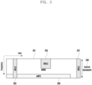
- FIGS. 3 and 4 are diagrams illustrating examples in which data for eMBB, URLLC, and mMTC, which are services considered in a 5G or NR system, are allocated in the frequency-time resources.
- FIGS. 3 and 4 there is provided a scheme of allocating frequency and time resources for transmitting information in each system.
- FIG. 3 is a diagram illustrating an example in which eMBB, URLLC, and mMTC data are allocated in the entire system frequency band.
- FIG. 3 illustrates data for eMBB, URLLC, and mMTC that have been allocated in the entire system frequency band 300. If URLLC data 303, 305, and 307 is produced and needs to be transmitted, while eMBB 301 and mMTC 309 are allocated and transmitted in a predetermined frequency band, the eMBB 301 and the mMTC 309 may empty previously allocated parts or may not perform transmission, so that the URLLC data 303, 305, and 307 may be transmitted.
- the URLLC data may be allocated to a part of the resource 301 where eMBB is allocated, and may be transmitted. If URLLC is additionally allocated and transmitted in the resource to which eMBB is allocated, eMBB data may not be transmitted in the overlapping frequency-time resources. Accordingly, the performance of transmission of the eMBB data may be decreased. In other words, the transmission of the eMBB data may fail due to the allocation of URLLC.
- FIG. 4 is a diagram illustrating an example in which eMBB, URLLC, and mMTC data are allocated in separate system frequency bands.
- the entire system frequency band 400 may be divided, and each sub-band 402, 404, and 406 may be used for transmitting a service and data.
- Information related to a configuration of the sub-bands may be determined in advance, and the information may be transmitted from a base station to a UE via higher signaling. Alternatively, a base station or a network node may arbitrarily determine sub-bands and provide services without separately transmitting sub-band configuration information to a UE.
- FIG. 4 illustrates that the sub-band 402 is used for transmission of eMBB data, the sub-band 404 is used for transmission of URCCL data, and the sub-band 406 is used for transmission of mMTC data.
- a downlink is a wireless transmission path of a signal that a base station transmits to a UE.
- An uplink is a wireless transmission path of a signal that a LTE transmits to a base station.
- the embodiment of the disclosure may be applicable to other communication systems having a similar technical background or a similar channel type.
- the embodiments of the disclosure may be modified by those skilled in the art without departing from the scope of the disclosure, and may be applied to other communication systems.
- PDSCH Physical channel
- signal conventionally used may be interchangeably used with the term “data” or "control signal”.
- data data or control signal.
- a PDSCH is a physical channel that delivers data
- a PDSCH may be considered as data in the description provided below.
- higher signaling is signal transferring from a base station to a LTE via a downlink data channel of a physical layer, or signal transferring from a LTE to a base station via an uplink data channel of a physical layer, which may also be referred to as RRC signaling or MAC control element (MAC CE).
- RRC signaling or MAC control element (MAC CE).
- MAC CE MAC control element
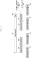
- FIG. 5 is a diagram illustrating an example of a process in which a single transport block is divided into multiple code blocks, and CRCs are added thereto.
- a CRC 503 may be added to the end or the front part of a single transport block (TB) 501 to be transmitted in an uplink or a downlink.
- the CRC 503 may have 16 bits, 25 bits, or a predetermined number of bits, or may have bits, the number of which is variable depending on a channel condition or the like.
- the CRC 503 may be used for determining whether channel coding is successfully performed.
- a block including the TB 501 and the CRC 503 may be divided into multiple code blocks (CB) 507, 509, 511, and 513 as shown in diagram 505.
- the maximum size for a codeblock is predetermined and is used for division.
- the last codeblock 513 may be smaller than the other codeblocks 507, 509, and 511.
- CRCs 517, 519, 521, and 523 may be added to the code blocks 507, 509, 511, and 513, respectively, as shown in the diagram 515.
- the CRC may have 16 bits, 24 bits, or a predetermined number of bits, and may be used for determining whether channel coding is successfully performed.
- + p 22 D 1 + p 23 by gCRC24A(D) may be determined as p 0 , p 1 , p 2 , p 3 , ... . , p L -1 , in case of the CRC p 0 , p 1 , p 2 , p 3 , ... . , p L -1 for TB data a 0 , a 1 , a 2 , a 3 , ... . , a A -1 .
- the length L of a CRC may be determined variously, such as 12, 16, 24, 32, 40, 48, 64, and the like.
- a CRC is added to a TB according to the described process, and the TB+CRC may be divided into N CBs 507, 509, 511, and 513.
- CRCs 517, 519, 521, and 523 may be added to the CBs 507, 509, 511, and 513 obtained via division, respectively, as shown in the diagram 515.
- a CRC added to a CB may have a length different from a length of a CRC added to a TB, or another cyclic generator polynomial may be used for producing a CRC.
- the CRC 503 added to the TB and the CRCs 517, 519, 521, and 523 added to the codeblocks may be omitted depending on the types of channel codes to be applied to the codeblocks.
- the CRCs 517, 519, 521, 523 to be respectively added to code blocks may be omitted.
- the CRCs 517, 519, 521, and 523 may be added to code blocks, as usual. In case that a polar code is used, a CRC may be added or may be omitted.
- the maximum length of a single code block may be determined based on the type of channel coding to be applied to a TB desired to be transmitted, and the TB and a CRC to be added to the TB may be divided into code blocks based on the maximum length of a code block.
- a CRC for a CB may be added to a CB obtained via division.
- a data bit of a CB and a CRC may be encoded into a channel code and coded bits are determined.
- the number of rate match bits may be determined as previously determined for each coded bit.
- the size of a TB (TBS) in the NR system may be calculated via the following steps.
- Step 1 calculates the number N RE ′ of REs allocated to PDSCH mapping in a single PRB within an allocated resource.
- N RE ′ may be calculated via N sc RB ⁇ N symb sh ⁇ N DMRS PRB ⁇ N oh PRB .
- N sc RB is 12, and N symb sh denotes the number of OFDM symbols allocated to a PDSCH.
- N DMRS PRB denotes the number of REs in a single PRB that a DMRS of the same CDM group occupies.
- N oh PRB denotes the number of REs occupied by overhead in a single PRB configured via higher signaling, and may be configured as one of 0, 6, 12, and 18.
- N RE may be calculated based on min 156 N RE ′ ⁇ n PRB
- n PRB may denote the number of PRBs allocated to a UE.
- Step 2 the number N info of temporary information bits may be calculated via N RE * R * Q m * v .
- R denotes a code rate
- Qm denotes a modulation order.
- Information associated with the value may be transferred via an MCS bit field of DCI and a predetermined Table.
- v denotes the number of allocated layers.
- N info ⁇ 3824 a TBS may be calculated according to step 3 described below. In other cases, a TBS may be calculated according to step 4.
- a value that is closest to N info ′ among values not less than N info ′ in Table 12 shown below may be determined as a TBS.
- a TBS may be determined based on a N info ′ value and [pseudo-code 1]. C shown below denotes the number of codeblocks included in a single TB.
- parity bits may be added thereto and may be output.
- the number of parity bits may differ depending on an LDCP base graph.
- a method of sending all parity bits produced via LDPC coding for a predetermined input may be referred to as full buffer rate matching (FBRM), and a method of limiting the number of transmittable parity bits may be referred to as a limited buffer rate matching (LBRM).
- FBRM full buffer rate matching
- LBRM limited buffer rate matching
- an LDPC encoder output is produced to be a circular buffer, and bits of the produced buffer are transmitted repeatedly as many times as the allocated resources allow.
- the length of the circular buffer is referred to as Ncb.
- Ncb N according to the FBRM method.
- Ncb is min( N , N ref )
- N ref is given as ⁇ TBS LBRM C ⁇ R LBRM ⁇
- R LBRM is determined to be 2/3.
- TBS LBRM the above-described method of obtaining a TBS may be used. In this instance, calculation may be performed by assuming the maximum number of layers and the maximum modulation order that a UE supports in a corresponding cell.
- the maximum modulation order Qm may be assumed to be 8 in case that the corresponding cell is configured to use an MCS table that supports 256QAM for at least one BWP. Otherwise, the maximum modulation order Qm may be assumed to be 6 (64QAM).
- a code rate may be assumed to be a maximum code rate of 948/1024.
- N RE is assumed to be 156 ⁇ n PRB .
- n PRB is assumed to be n PRB,LBRM .
- n PRB,LBRM may be given as shown in Table 13 below.
- the maximum data rate that a UE supports in the NR system may be determined according to Equation 2 below.
- f ( j ) a scaling index
- ⁇ a subcarrier spacing.
- T s ⁇ denotes an average OFDM symbol length
- T s ⁇ may be calculated based on 10 ⁇ 3 14 ⁇ 2 ⁇
- N PRB BW j ⁇ denotes the maximum number of RBs in BW(j).
- OH ( j ) is an overhead value, and may be 0.14 in a downlink and 0.18 in an uplink of FR1 (a 6GHz or lower band), and may be 0.08 in a downlink and 0.10 in an uplink of FR2 (a band higher than 6GHz).
- the maximum data rate in a downlink may be calculated by using Equation 2, as shown in Table 15 below.
- an actual data rate measurable by a LTE in actual data transmission may be a value obtained by dividing the amount of data by a data transmission time. This may be a value obtained by dividing, by a TTI length, a TBS in case of 1 TB transmission or the sum of TBSs in case of 2 TB transmission.
- the actual maximum data rate in a downlink may be determined based on the number of allocated PDSCH symbols, as shown in Table 16 below.
- the maximum data rate that a UE supports may be identified via Table 15, and an actual data rate based on an allocated TBS may be identified via Table 16. In this instance, an actual data rate may happen to be higher than the maximum data rate depending on scheduling information.
- a data rate supportable by a UE may be mutually agreed upon between a base station and the UE. That may be calculated using the maximum frequency band, the maximum modulation order, the maximum number of layers, and the like supported by the UE. However, the calculated data rate may be different from a value calculated based on a transport block (TB) size (TBS) and the length of a transmission time interval (TTI) used for actual data transmission.
- TB transport block
- TTI transmission time interval
- the UE may happen to be assigned with a larger TBS than a value corresponding to a data rate supported by the UE itself.
- there may be the restriction of a schedulable TBS depending on a data rate supported by the UE.
- FIG. 6 is a diagram illustrating a synchronization signal (SS) of the NR system and a physical broadcast channel (PBCH) which are mapped in the frequency and time domain.
- SS synchronization signal
- PBCH physical broadcast channel
- a primary synchronization signal (PSS) 601, a secondary synchronization signal (SSS) 603, and PBCHs are mapped to 4 OFDM symbols.
- PSS primary synchronization signal
- SSS secondary synchronization signal
- PBCHs are mapped to 20 RBs.
- the table in FIG. 6 shows the frequency band of 20 RBs that varies depending on a subcarrier spacing (SCS).
- SCS subcarrier spacing
- a resource area in which the PSS, SSS, and PBCHs are transmitted is referred to as an SS/PBCH block (SS/PBCH block).
- the SS/PBCH block may be referred to as an SSB block.
- FIG. 7 is a diagram illustrating symbols in which an SS/PBCH block is capable of being transmitted based on a subcarrier spacing.
- a subcarrier spacing may be set to 15kHz, 30kHz, 120kHz, 240kHz, or the like, and the location of a symbol in which an SS/PBCH block (or an SSB block) is capable of being located may be determined based on each subcarrier spacing.
- FIG. 7 illustrates the location of a symbol in which an SSB is capable of being transmitted based on a subcarrier spacing in symbols within 1ms, but it is not that an SSB is always transmitted in the area marked in FIG. 7 . Therefore, the location in which an SSB block is transmitted may be configured for a UE via system information or dedicated signaling.
- a UE is distant from a base station and thus, a signal transmitted from the UE may be received by the base station after a propagation delay time (propagation delay).
- the propagation delay time is a value obtained by dividing, by the speed of light, a path in which an electromagnetic wave is transferred from the UE to the base station.
- the propagation delay time may be a value obtained by dividing the distance from the UE to the base station by the speed of light.
- a signal transmitted from the UE may be received by the base station in approximately 0.34 msec.
- a signal transmitted from the base station is also received by the UE in approximately 0.34 msec.
- a time that a signal transmitted from the UE arrives at the base station may differ depending on the distance between the UE and the base station. Therefore, in case that multiple UEs located in different locations simultaneously transmit signals, times that the signals arrive at a base station may be different from one another.
- a time at which an uplink signal is to be transmitted may be set to be different for each LTE depending on a location.
- timing advance In the 5G, NR, and LTE systems, that is referred to as timing advance.
- FIG. 8 is a diagram illustrating a UE processing time based on timing advance when the LTE receives a first signal and transmits a second signal in response thereto in the 5G or NR system according to an embodiment.
- a base station transmits an uplink scheduling grant (LTL grant) or a downlink control signal and data (DL grant and DL data) to a UE in slot n 802
- the UE may receive the uplink scheduling grant or the downlink control signal and the data in slot n 804.
- the UE may receive a signal a propagation delay time (Tp) 810 later than a time at which the base station transmits the signal.
- Tp propagation delay time
- the LTE transmits a corresponding second signal in slot n+4 806.
- a period of time 814 allowed for the LTE to prepare transmission of uplink data after receiving an uplink scheduling grant or to prepare transferring an HARQ ACK or NACK after receiving downlink data may be a time excluding a TA from a time corresponding to three slots.
- the base station may calculate the absolute value of a TA of the corresponding UE.
- the base station may calculate the absolute value of a TA by adding, to a TA value that the base station initially transmits to the UE at a random access stage at the initial access, a change in the TA value transferred via higher signaling or by subtracting the change therefrom.
- the absolute value of the TA may be a value obtained by subtracting the start time of an n th TTI received by the UE from the start time of an n th TTI transmitted by the UE.
- a signal is transmitted or received in units of subframes, each subframe having a transmission time interval (TTI) of 1ms.
- TTI transmission time interval
- a LTE a short-TTI LTE
- a transmission time interval may be shorter than 1ms.
- the short-TTI LTE is suitable for a service that takes latency as an important factor, such as a voice over LTE (VoLTE) service, a remote control service, or the like.
- the short-TTI UE is a device that is capable of implementing mission-critical Internet of Things (IoT) based on a cellular network.
- IoT mission-critical Internet of Things
- DCI that schedules a PDSCH may indicate a K1 value corresponding to timing information associated with a timing at which the LTE transmits HARQ-ACK information associated with the PDSCH.
- the UE may transmit HARQ-ACK information to the base station in case it is not indicated to transmit HARQ-ACK information before symbol L1 by including timing advance. That is, the HARQ-ACK information may be transmitted from the UE to the base station at the same time of or after symbol L1, by including timing advance. In case that it is indicated to transmit HARQ-ACK information before symbol L1 by including timing advance, HARQ-ACK information may not be valid HARQ-ACK information in HARQ-ACK transmission from the UE to the base station.
- Symbol L1 may be a first symbol in which a cyclic prefix (CP) starts T proc, 1 after the last point of a PDSCH.
- T proc, 1 may be calculated as given in Equation 3 below.
- T proc , 1 N 1 + d 1,1 + d 1,2 2048 + 144 ⁇ ⁇ 2 ⁇ ⁇ ⁇ T C
- N1, d1,1, d1,2, ⁇ , ⁇ , and TC may be defined as described below.
- the UE may indicate a K2 value corresponding to timing information of a timing at which the LTE transmits uplink data or a PUSCH.
- the LTE may transmit a PUSCH to the base station in case that it is not indicated to transmit the PUSCH before symbol L2 by including timing advance. That is, by including timing advance, the PUSCH may be transmitted from the UE to the base station at the same time of or after symbol L2. In case that it is indicated to transmit a PUSCH before symbol L2 by including timing advance, the LTE may disregard an uplink scheduling grant control information obtained from the base station.
- the symbol L2 may be a first symbol in which a CP of a PUSCH symbol starts, wherein the PUSCH symbol needs to be transmitted T proc ,2 after the last point of a PDCCH including a scheduling grant.
- T proc ,2 may be calculated as given in Equation 4 below.
- T proc , 2 N 2 + d 2,1 2048 + 144 ⁇ ⁇ 2 ⁇ ⁇ ⁇ T C
- N2, d2, 1, ⁇ , ⁇ , and TC may be defined as below.
- the 5G or NR system may configure a frequency band part (BWP) in a single carrier and may designate a predetermined UE to perform transmission or reception in the configured BWP. This is to reduce the amount of power consumed by a UE.
- a base may configure a plurality of BWPs, and may change activated BWP using control information.
- a period of time that the UE is capable of spending in changing a BWP may be defined as shown in Table 19 below. [Table 19] Frequency Range Scenario Type 1 delay (us) Type 2 delay (us) 1 1 600 2000 2 600 2000 3 600 2000 4 400 950 2 1 600 2000 2 600 2000 3 600 2000 4 400 950
- frequency range 1 denotes a 6GHz or lower frequency band
- frequency range 2 denotes a 6GHz or higher frequency band.
- type 1 and type 2 may be determined based on UE capability.
- scenarios 1, 2, 3, and 4 may be given as shown in Table 20 below. [Table 20] change in center frequency no change in center frequency change in frequency bandwidth scenario 3 scenario 2 no change in frequency bandwidth scenario 1 scenario 4 in case that subcarrier spacing is changed
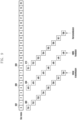
- FIG. 9 is a diagram illustrating an example of scheduling and transmitting data (e.g., TBs) in slots, receiving a HARQ-ACK feedback associated with the corresponding data, and performing retransmission based on the feedback.
- TB 1 900 is transmitted initially in slot 0 902, and an ACK/NACK feedback 904 thereto is transmitted in slot 4 906.
- retransmission 910 of TB 1 may be performed in slot 8 908.
- the point in time at which the ACK/NACK feedback is transmitted and the point in time at which retransmission is performed may be determined in advance, or may be determined based on a value indicated by control information and/or a higher layer signaling.
- FIG. 9 illustrates an example in which TB1 to TB8 are sequentially scheduled in slots from slot 0. That may be the case in which HARQ process IDs 0 to 7 are assigned to TB1 to TB8, respectively, and transmission is performed. In case that the number of HARQ process IDs that a base station and a LTE are capable of using is only four, eight different TBs may not be successively transmitted.
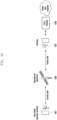
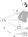
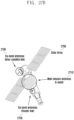
- FIG. 10 is a diagram illustrating an example of a communication system that uses a satellite.
- the satellite 1003 may transfer the signal to a base station 1005, and the base station 1005 may process the received signal and transmit the signal including a request for a subsequent operation to be performed thereon to the UE 1001. This may be transmitted via the satellite 1003, again.
- the distance between the UE 1001 and the satellite 1003 is long and the distance between the satellite 1003 and the base station 1005 is also long and thus, a period of time spent in data transmission or reception between the LTE 1001 and the base station 1005 may be long.
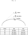
- FIG. 11 is a diagram illustrating a revolution cycle of a communication satellite around the earth based on the altitude or height of the satellite. Satellites for communication may be classified based on the orbit of a satellite, such as a low Earth orbit (LEO), a middle Earth orbit (MEO), a geostationary Earth orbit (GEO), and the like.
- LEO low Earth orbit
- GEO geostationary Earth orbit
- a GEO 1100 is a satellite located at an altitude of approximately 36000km
- an MEO 1110 a satellite located at an altitude in the range of 5000 to 15000km
- an LEO is a satellite located at an altitude in the range of 500 to 1000km.
- the revolution cycle of a satellite around the earth differs depending on an altitude. In the case of the GEO 1100, a revolution cycle is approximately 24 hours.
- a revolution cycle is approximately 6 hours.
- a revolution cycle is approximately 90 to 120 minutes.
- a LEO ( ⁇ 2,000km) satellite has a relatively low altitude and thus, a propagation delay time (a period of time spent when a signal transmitted from a transmitter arrives at a receiver) and a loss may be lower than a GEO (36,000km) satellite.
- GEO 36,000km
- a thing that is not a GEO satellite is referred to as a non-geostationary orbit (NGSO).
- NGSO non-geostationary orbit
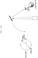
- FIG. 12 is a conceptual diagram of satellite-UE direct communication.
- a satellite 1200 located at an altitude higher than 100km via a rocket may perform signal transmission or reception with a UE 1210 on the earth, and may also perform signal transmission or reception with a ground station 1220 connected to a base station on the earth (DU farms) 1230.
- FIG. 13 is a diagram illustrating a scenario of utilizing satellite-UE direct communication.
- the satellite-UE direct communication may support a communication service that is specialized in complementing the limit of coverage of a terrestrial network. For example, by embodying a satellite-UE direct communication function in a UE, a user emergency signal and/or disaster signal may be transmitted or received beyond a terrestrial communication coverage area as shown in diagram 1300, a mobile communication service may be provided to a user in an area where terrestrial network communication is unavailable such as a vessel and/or an airplane as shown in diagram 1310, the location of a vessel, a truck, and/or a drone may be traced and controlled in real time without restriction based on a border as shown in diagram 1320.
- the UE may function as a backhaul of the base station by supporting a satellite communication function to a base station, and may utilize satellite communication so as to perform a backhaul function in case that the base station is physically far away as shown in diagram 1330.
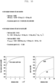
- FIG. 14 is a diagram illustrating an example of calculation of an expected data transmission rate (throughput) in an uplink in case that an LEO satellite located at an altitude of 1200 km and a UE on the earth perform direct communication.
- transmission power effective isotropic radiated power (EIRP) of a UE on the earth is 23 dBm
- a path loss of a wireless channel to a satellite is 169.8 dB
- a satellite reception antenna gain is 30 dBi
- an attainable signal to-noise ratio (SNR) may be estimated to be -2.63 dB.
- the pathloss may include a pathloss in space, a loss in the atmosphere, and the like.
- a signal-to-interference ratio SIR
- SINR signal-to-interference and noise ratio
- FIG. 15 is a diagram illustrating an example of calculation of an expected data transmission rate (throughput) in an uplink in case that a GEO satellite located at an altitude of 35,786 km and a UE on the earth perform direct communication.
- transmission power EIRP of a UE on the earth is 23 dBm
- a path loss of a wireless channel to a satellite is 195.9 dB
- a satellite reception antenna gain is 51 dBi
- an attainable SNR may be estimated to be -10.8 dB.
- the pathloss may include a pathloss in space, a loss in the atmosphere, and the like.
- an SINR is calculated to be -11 dB.
- a transmission speed of 21 kbps may be attainable. This may be a result of repetitively performing transmission three times.
- FIG. 16 is a diagram illustrating a pathloss value based on a pathloss model between a UE and a satellite, and a pathloss based on a pathloss model between a UE and a terrestrial base station.
- d denotes a distance
- f c denotes the frequency of a signal.
- a pathloss (FSPL) 1600 is inversely proportional to the square of a distance.
- a path loss (PL 2 , PL' Uma-NLOS ) 1610 and 1620 on the earth where air is present and communication between the UE and the terrestrial base station (terrestrial gNB) is performed is inversely proportional to approximately the 4 th power of a distance.
- Doppler shift that is, a frequency movement (offset) of a transmitted signal, is incurred since a satellite continuously moves fast.
- FIG. 17 is a diagram illustrating a calculation equation and a calculation result in associated with the amount of Doppler shift that a signal experiences when the signal transferred from a satellite is received by a user on the earth according to the altitude and location of the satellite and the location of the user of a UE on the earth.
- R denotes the radius of the earth
- h denotes the altitude of a satellite
- v denotes the speed of the revolution of a satellite around the earth
- f c denotes the frequency of a signal.
- the speed of a satellite may be calculated based on the altitude of the satellite, and may be a speed at which gravity, the force of the earth pulling the satellite, is equal to centripetal force incurred when the satellite revolves. This may be calculated as described in FIG. 18 .
- FIG. 18 is a diagram illustrating the speed of a satellite calculated at the altitude of the satellite. As identified in FIG. 17 , angle ⁇ is determined based on an angle of altitude (elevation angle) ⁇ and thus, a Doppler shift value may be determined based on the elevation angle ⁇ .
- FIG. 19 is a diagram illustrating Doppler shift that different UEs experience in a single beam that a satellite transmits to the earth.
- Doppler shift that each of UE 1 1900 and UE 2 1910 goes through is calculated based on the elevation angle ⁇ . That is a result obtained on the assumption of a center frequency of 2 GHz, a satellite altitude of 700 km, a single beam's diameter of 50km on the earth, and a UE speed of 0.
- the Doppler shift is calculated by disregarding an effect of the rotation speed of the earth, which is considered as a minimal effect since it is slower than the speed of the satellite.
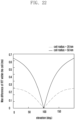
- FIG. 20 is a diagram illustrating a difference in Doppler shift incurred in a single beam, depending on the location of a satellite determined based on an elevation angle.
- the difference in Doppler shift in the beam (or cell) is the highest.
- Doppler shift values at one end and the other end of the beam have a positive value and a negative value, respectively.
- the distance from the satellite to a user on the earth is long and thus, a long delay may be incurred when compared to terrestrial network communication.
- FIG. 21 is a diagram illustrating a latency taken from a LTE to a satellite and a round trip latency among UE-satellite-base station, depending on the location of a satellite determined based on an elevation angle.
- Graph 2100 shows a latency taken from a UE to a satellite
- graph 2110 shows a round trip latency among a LTE, a satellite, and a base station.
- the latency between the satellite and base station is assumed to be the same as the latency between the UE and the satellite.
- FIG. 22 is a diagram illustrating the maximum difference value in a round trip latency that differs depending on the location of a user in a single beam. For example, in case that a beam radius (or a cell radius) is 20 km, the difference in latency of a round trip to the satellite between UEs at different locations within a beam, the latency varying depending on the location of the satellite, may be less than or equal to approximately 0.28 ms.
- the situation in which a UE performs signal transmission or reception with a base station in satellite communication may be the situation in which the signal is transferred via a satellite. That is, in a downlink, the satellite receives a signal that the base station transmits to the satellite, and the satellite transfers the same to the UE. In an uplink, the satellite receives a signal that the UE transmits, and transfers the same to the base station. In the above description, the satellite receives a signal and may transmit the same as it is by only shifting a frequency, or may perform signal processing based on the received signal such as decoding and re-encoding and transfer the same.
- a UE may access a base station via the following procedure.
- the maximum limited time in which the UE that transmits the random access preamble in step 3 receives the RAR in the step may be configured by the SIB transmitted in step 2. For example, this may be limitingly configured as a maximum of 10ms, a maximum of 40ms, or the like. That is, in case that the LTE that transmits the preamble in step 3 fails to receive an RAR, for example, within a time determined based on the configured maximum time of 10 ms, the UE may transmit a preamble again.
- the RAR may include scheduling information that allocates a resource for a signal to be transmitted by the UE in step 5 which is a subsequent step.
- FIG. 23 is a diagram illustrating an example of the structure of information of an RAR.
- An RAR 2300 may be, for example, a MAC PDU, and may include information 2310 associated with timing advance (TA) to be applied by the UE and a temporary C-RNTI value 2320 to be used from the next step.
- TA timing advance
- a propagation delay incurred in satellite communication may be a problem.
- a period (random access window) in which the UE is capable of receiving an RAR in step 4 after transmitting the random access preamble (or PRACH preamble) in step 3, that is, the maximum time for reception may be configured via ra-ResponseWindow.
- the maximum time may be configured as a maximum of 10 ms.
- FIG. 24 is a diagram illustrating an example of a relationship between a reception point of an PRACH preamble configuration resource and a reception point of an RAR in the LTE system.
- FIG. 25 is a diagram illustrating an example of a relationship between a reception point of a PRACH preamble configuration resource and a reception point of an RAR in the 5G NR system.
- a random access window 2410 starts.
- the UE may determine that the preamble is successfully transmitted.
- a random access window 2510 start from a control information area for RAR scheduling that appears for the first time after transmission 2500 of a PRACH (random access preamble).
- the UE may determine that the PRACH preamble is successfully transmitted.
- FIG. 26 is a diagram illustrating an example of timing of a downlink frame and an uplink frame from the perspective of a UE.
- N TA in the above may be transferred via an RAR or may be determined based on a MAC CE.
- N TA,offset may be a value configured for the LTE or a value determined based on a predetermined value.
- the RAR of the 5G NR system may indicate a T A value.
- T A may indicate one value among 0, 1, 2, ..., 3846.
- T A information indicated via the MAC CE may indicate one of 0, 1, 2, ..., 63. This may be used for calculating a new TA value by being added to or subtracted from the existing TA value.
- the UE may apply the TA value indicated as described above to uplink transmission, after a predetermined period of time elapses.
- FIG. 27A is a diagram illustrating an example of continuous movement of a satellite from the perspective of a UE located on the ground of the earth or on the earth, as the satellite revolves around the earth along a satellite orbit.
- the distance between the UE and the satellite differs depending on an elevation angle at which the UE faces the satellite and thus, a latency (propagation delay) between the UE and the satellite and the base station may be changed.
- FIG. 27B is a diagram illustrating an example of the structure of an artificial satellite.
- a satellite may include a solar panel or solar array 2700 for sunlight or solar power generation, a transmission or reception antenna (main mission antenna) 2710 for communicating with a UE, a transmission or reception antenna (feeder link antenna) 2720 for communicating with a terrestrial station, an a transmission or reception antenna (inter-satellite link) 2730 for inter-satellite communication, a processor for controlling transmission or reception and performing signal processing, and the like.
- an antenna for inter- satellite signal transmission or reception may not be disposed.
- FIG. 27B illustrates that an L band of 1 to 2GHz is used for communication with the UE, K band (in the range of 18 to 26.5 GHz), Ka band (in the range of 26.5 to 40 GHz), and Ku band (in the range of 12 to 18 GHz) which are high-frequency bands may also be usable.
- K band in the range of 18 to 26.5 GHz
- Ka band in the range of 26.5 to 40 GHz
- Ku band in the range of 12 to 18 GHz
- TA may be transmitted via a MAC control element (MAC CE), for example, timing advance command MAC CE, an absolute timing advance command MAC CE, or the like.
- MAC CE MAC control element
- a message transferred from the MAC layer to the physical layer may include one or more MAC sub-PDUs.
- Each MAC sub-PDU may include one of the following information.
- Each MAC sub-header may correspond to a MAC SDU, a MAC CE, or padding.
- a message transferred from the MAC layer to the physical layer may be configured as shown in FIG. 28 in the case of a downlink, and as shown in FIG. 29 in the case of an uplink.
- FIG. 28 is a diagram schematically illustrating an example of a message transferred from the MAC layer to the physical layer in a downlink in a communication system according to various embodiments of the disclosure.
- an example of a message transferred from the MAC layer to the physical layer in the downlink may be a downlink MAC PDU (DL MAC PDU).
- a MAC sub-PDU including MAC CE 1 may include an R/LCID sub-header and a fixed-sized MAC CE
- a MAC sub-PDU including MAC CE 2 may include an R/F/LCID/L sub-header and a variable-sized MAC CE
- a MAC sub-PDU including a MAC SDU may include an R/F/LCID/L sub-header and a MAC SUD.
- an LCID denotes a logical channel ID field.
- the LCID field may indicate the instance of a corresponding MAC SDU or the type of a corresponding MAC CE, or padding. This will be described with reference to Table 21 and Table 22 in detail.
- Table 21 lists an LCID value for a DL-SCH.
- Table 22 lists an LCID value for an UL-SCH.
- One LCID field is present for each MAC sub-header, and the size of the LCID field is 6 bits.
- the LCID field is configured as, for example, "34”
- one additional octet is present in a MAC sub-header including an eLCID field, and this may comply with the octet including the LCID field.
- the LCID field is configured as, for example, "33”
- two additional octets are present in a MAC sub-header including an eLCID field, and the two octets may comply with the octet including the LCID field.
- the eLCID denotes an extended logical channel ID field, and may indicate a logical channel instance of a corresponding MAC SDU or the type of a corresponding MAC CE.
- the size of the eLCID field may be 8 bits or 16 bits.
- L denotes a length field
- the length field may indicate the length of a corresponding MAC SDU or the length of a variable-sized MAC CE.
- a single length field is present for each MAC sub-header, excluding sub-headers corresponding to MAC SDUs including the fixed-sized MAC CEs, padding, or UL common control channel (CCCH).
- the size of the length field may be indicated by an F field.
- F denotes a format field, and indicates the size of a length field.
- a single F field may be present for each MAC sub-header, excluding MAC SDUs including fixed MAC CEs, padding, and a LTL CCCH.
- the size of the F field is 1 bit. For example, a value of 0 indicates 8 bits of the length field. As another example, a value of 1 indicates 16 bits of the length field.
- R denotes a reserved bit and, for example, may be configured as "0".
- MAC CEs for example, MAC CE 1 and MAC CE 2 are disposed together, and a MAC sub-PDU(s) including a MAC CE(s) may be disposed before a MAC sub-PDU including a MAC SDU and a MAC sub-PDU including padding.
- the size of the padding may be zero.
- FIG. 29 is a diagram schematically illustrating an example of a message transferred from the MAC layer to the physical layer in an uplink in a communication system according to various embodiments of the disclosure.
- an example of a message transferred from the MAC layer to the physical layer in the uplink may be an uplink MAC PDU (UL MAC PDU).
- a MAC sub-PDU including MAC CE 1 may include an R/LCID sub-header and a fixed-sized MAC CE
- a MAC sub-PDU including MAC CE 2 may include an R/F/LCID/L sub-header and a variable-sized MAC CE
- a MAC sub-PDU including a MAC SDU may include an R/F/LCID/L sub-header and a MAC SUD.
- MAC CEs for example, MAC CE 1 and MAC CE 2 are disposed together, and a MAC sub-PDU(s) including a MAC CE(s) may be disposed after a MAC sub-PDU including a MAC SDU and before a MAC sub-PDU including padding.
- the size of the padding may be zero.
- an LCID included in the sub-header of the MAC layer may indicate the type of a MAC SDU or MAC CE transmitted, or the like.
- a logical channel ID or an extended logical channel ID eLCID
- An example of mapping between an LCID index and the type of a MAC SDU or MAC CE or the like may be listed as shown in Table 21 below.
- An example of mapping between an eLCID index and the type of a MAC SDU or MAC CE or the like may be listed as shown in Table 22 below.
- an LCID may indicate the instance of a logical channel of a MAC SDU, the type of a MAC CE, or padding information of a downlink shared channel (DL-SCH) and an uplink shared channel (UL-SCH).
- DL-SCH downlink shared channel
- UL-SCH uplink shared channel
- a single LCID is mapped for each MAC sub-header and, for example, an LCID may be embodied as 6 bits.
- FIG. 30 is a diagram schematically illustrating an example of the format of the MAC payload of an RAR or the MAC payload of MsgB in a communication system according to various embodiments of the disclosure.
- the MAC payload of an RAR may be referred to as a MAC RAR, and the MAC RAR may include the following fields.
- the term “base station (BS)” may be a component (or a component set) configured to provide radio access, such as a transmit point (TP), a transmit-receive point (TRP), an enhanced node B (eNodeB or eNB), a 5G base station (gNB), a macrocell, a femtocell, a WiFi access point (AP), or other wireless-enable devices based on a wireless communication system type.
- TP transmit point
- TRP transmit-receive point
- eNodeB or eNB enhanced node B
- gNB 5G base station
- AP WiFi access point
- Base stations may provide radio access based on one or more radio protocols, for example, a 5G 3GPP new radio interface/access (NR), a long term evolution (LTE), an LTE advanced (LTE-A), a high speed packet access (HSPA), Wi-Fi 802.11a/b/g/n/ac, or the like.
- NR 5G 3GPP new radio interface/access
- LTE long term evolution
- LTE-A LTE advanced
- HSPA high speed packet access
- Wi-Fi 802.11a/b/g/n/ac Wi-Fi 802.11a/b/g/n/ac, or the like.
- terminal may be a component such as a "user equipment (LTE)", a “mobile station”, a “subscriber station”, a “remote terminal”, a “wireless terminal”, a “receive point”, or a “user device”.
- LTE user equipment
- mobile station a mobile station
- subscriber station a subscriber station
- remote terminal a wireless terminal
- wireless point a “receive point”
- user device a component such as a "user equipment (LTE)", a "mobile station”, a “subscriber station”, a “remote terminal”, a “wireless terminal”, a “receive point”, or a “user device”.
- terminal is used for indicating a device that accesses a base station in various embodiments of the disclosure, irrespective of whether the terminal is a mobile device (a mobile phone or smartphone) or whether the terminal is considered as a stationary device (e.g., a desktop computer or a vending machine).
- a satellite in various embodiments of the disclosure may
- TA may be interchangeably used with the term “TA information”, “TA value”, or "TA index”.
- first signal data or control information that a base station transmits to a UE
- second signal data or control information that a base station transmits to a UE
- the first signal may include DCI, a UL grant, a PDCCH, a PDSCH, an RAR, and the like
- the second signal associated with the first signal may include a PUCCH, a PUSCH, msg 3, and the like.
- the second signal corresponding to the first signal may be a PUSCH including uplink data.
- a difference (gap) in the point in time of transmission or reception between the first signal and the second signal may be a value predetermined between a LTE and a base station Unlike the above, the difference in the point in time for transmission or reception between the first signal and the second signal may be determined via indication by a base station or may be determined based on a value transferred via higher signaling.
- a satellite navigation system may be referred to as a GNSS, and the GNSS may include, for example, GPS in the U.S., GLONASS in Russia, Galileo in EU, Beidou in China, and the like.
- the GNSS may include a regional navigation satellite system (RNSS), and the RNSS may include, for example, IRNSS in India, QZSS in Japan, KPS in Korea, and the like.
- a signal transmitted in the GNSS may include at least one information among supplementary navigation information, normal operation state of a satellite, a satellite time, a satellite ephemeris, the altitude of a satellite, a reference time, and various correction data.
- FIG. 31 is a diagram schematically illustrating an uplink transmission operation in case that a UE directly calculates a TA value in a communication system according to various embodiments of the disclosure.
- a UE may perform estimation of a propagation delay between a satellite and a UE based on the location of the UE and the location of the satellite, may correct the estimated propagation delay for itself, and may perform uplink transmission.
- the satellite may transmit information related to the location of the satellite via broadcast information
- the UE may receive the information related to the location of the satellite transmitted by the satellite, and may compare the location of the satellite and the location of the UE itself.
- the UE may identify the location of the UE itself by utilizing, for example, a global positioning system (GPS) or the like.
- GPS global positioning system
- the scheme of identifying the location of the LTE may be embodied in various formats, and a detailed description thereof will be omitted.
- the UE may estimate a propagation delay incurred when an electromagnetic wave is transferred from the UE to the satellite, and may calculate an uplink transmission time based on the estimated propagation delay. For example, on the assumption that the UE receives a downlink signal in slot n at a predetermined point in time in a downlink, and the UE needs to transmit an uplink signal corresponding to the received downlink signal in slot n+k, the UE may transmit the uplink signal a predetermined period of time, for example, 2*Td, earlier than the slot n+k.
- Td may correspond to a propagation delay taken from the UE to the satellite calculated based on the location of the satellite and the location of the UE.
- the propagation delay Td may be, for example, a value obtained by dividing, by the speed of light, the distance between the UE and the satellite.
- the location of the satellite may be a value calculated based on the slot n+k in which the UE transmits an uplink signal, and the location of the satellite in the slot n and the location of the satellite in the slot n+k may be changed as the satellite moves.
- the satellite navigation system such as a GPS may include one or more satellites, and each of the one or more satellites may transmit a signal including information such as a time, a location, and the like.
- the UE may receive a signal from each of one or more satellites of the satellite navigation system, and may identify the location of the UE itself based on the signal received from each of the one or more satellites.
- an NTN satellite may be a communication satellite that performs a function of transferring a signal in order to connect the UE to the base station.
- a GNSS satellite may be a satellite for transmitting a signal of a satellite navigation system. It should be construed that the UE is expressed as a UE, and a base station is expressed as a ground station/DU, or the like in FIG. 31 .
- FIG. 32 is a diagram schematically illustrating an example of a difference in propagation delay time between a terrestrial network and a satellite network in a communication system according to various embodiments of the disclosure.
- the distance between a UE and a base station in a terrestrial network is considered as, for example, approximately a maximum of 100 km and thus, a propagation delay less than or equal to 1 ms may be incurred between the UE and the base station.
- the distance between the UE and a satellite in the satellite network may be thousands of km, and the distance between the satellite and the base station may be also thousands km and thus, a propagation delay in the satellite network may be significantly higher than a propagation delay in the terrestrial network.
- a propagation delay may differ depending on the altitude and elevation angle of the satellite in the satellite network communication.
- FIG. 32 illustrates a UE-satellite distance and a round trip latency (round trip time (RTT)) of an electromagnetic wave depending on an elevation angle in case that the altitude of the satellite is 700 km.
- RTT round trip time
- a low orbit satellite is assumed.
- a radio round trip latency radio round trip time (radio RTT)) in the range of 40.9 ms to 9.3 ms may be incurred.
- the radio RTT may include a round trip time spent in signal transmission or reception between a transmitter and a receiver, and a processing time taken in a counterpart node.
- FIG. 33 is a diagram schematically illustrating an example of applying TA to a terrestrial network and a satellite network in a communication system according to various embodiments of the disclosure.
- the maximum propagation delay time in the terrestrial network is within 1 or 2 ms and thus, from the perspective of a base station, a slot timing at which a downlink signal is transmitted and a slot timing at which an uplink signal is received may be matched by using an TA function provided in the LTE and 5G NR systems (i.e., matching the index of a downlink slot and the index of an uplink slot). That is, in case that a UE transmits an uplink signal as much time as a TA value, indicated by the base station, earlier than a downlink time point, the point in time at which the base station receives the uplink signal transmitted by the LTE may match the downlink time point of the base station.
- the base station indicates a TA value via an RAR
- the UE transmits, based on the TA value, a PUSCH signal in slot n+4 scheduled by the base station, and the base station receives the PUSCH signal transmitted by the LTE in the slot n+4 in the terrestrial network.
- a propagation delay incurred in the satellite network is approximately dozens of ms and is significantly higher than a propagation delay incurred in the terrestrial network, and the propagation delay is higher than the maximum value of TA considered in the legacy LTE and 5G NR systems.
- the base station receives a PUSCH signal that the UE transmits in slot n+4+K including a delay of slot K, as opposed to receiving the PUSCH signal in the scheduled slot n+4, since the base station is incapable of indicating a TA value to the LTE in the satellite network.
- FIG. 34 is a diagram schematically illustrating an example of the maximum difference in round trip latency in case that a plurality of UEs are located in a single beam that a satellite supports in a communication system according to various embodiments of the disclosure.
- a satellite 3400 may support a plurality of beams, and a plurality of UEs may be located in one of the plurality of beams supported by the satellite 3400.
- FIG. 34 illustrates an example of the maximum difference value among differences in round trip latency incurred among the LTE, the satellite, and the base station.
- the maximum difference value of the round trip latency that the UE may have depending on an elevation angle is decreased.
- the maximum difference value of the round trip latency depending on the radius of a cell may be decreased.
- FIG. 35 is a diagram schematically illustrating an example of a wireless round trip latency between a UE and a base station, which varies depending on the movement of a satellite in a communication system according to various embodiments of the disclosure.
- a satellite moves along its orbit, and as the satellite moves, a round trip latency between a UE and a base station may also change.
- the satellite moves along its orbit and thus, the round trip latency between the UE and the base station may change over time. That is, in the case of a terrestrial network, generally, a round trip latency between the UE and the base station changes less than a predetermined period of time although time elapses and thus, the change is low. Conversely, in the case of a satellite network, a round trip latency between the LTE and the base station significantly highly changes over time and thus, the change in the round trip latency between the UE and the base station is significantly high.
- the UE may receive a signal from each of one or more GNSS satellites, may calculate the location of the UE based on the signal received from each of the one or more GNSS satellites, and may also identify a reference time at each of the one or more GNSS satellites.
- the LTE may calculate the actual location of the LTE based on the average of the plurality of locations, a location corresponding to a received signal having the strongest intensity among the plurality of locations, an average value of the plurality of locations based on signal intensities (e.g., a method of applying a weight to a location corresponding to a signal having a high intensity), and the like.
- the method of calculating the location of the LTE based on signals received from the plurality of GNSS satellites may be embodied in various ways, and a detailed description thereof will be omitted.
- a time obtained from a GNSS or a base station's time that the base station transfers may be based on, for example, a coordinated universal time (UTC), and this is based on a time from 00 seconds, 00 minutes, and 00 hours on January 1 st , 1900 of the Gregorian calendar. This may differ depending on the type of GNSS system, and a reference time zone shown in Table 23 below may be used.
- UTC coordinated universal time
- NavIC System Time start epoch defined as 13 seconds before midnight between 21st - August and 22nd August 1999; i.e., NaviC System Time was equal to 00:00:00 at August 21 st, 1999 - 23:55:47 UTC (BIPM).
- NavIC denotes a navigation with Indian constellation
- QZS denotes a Quasi Zenith satellite
- QZSS denotes a Quasi-Zenith satellite system
- QZST denotes a Quasi-Zenith system time
- SBAS denotes a space based augmentation system
- BDS denotes a Beidou navigation satellite system.
- the base station may indicate the type of GNSS system which is the reference of location or time information that the base station uses, and may use an indicator as shown in Table 24 below.
- Table 24 Value of gnss-TO-ID Indication 1 GPS 2 Galileo 3 QZSS 4 GLONASS 5 BDS 6 NavIC 7-15 reserved
- the LTE may calculate a period of time to be spent in transferring a signal from the NTN satellite to the LTE, and based thereon, may determine a TA value.
- the UE may take into consideration the distance from the NTN satellite to the base station on the earth, or together with the distance from the NTN satellite to another NTN satellite in case a corresponding signal is transferred to the base station on the earth via the other NTN satellite.
- the LTE may obtain reference time information from information transferred from the GNSS satellite, may compare time information transmitted from the NTN satellite and the reference time information obtained from the GNSS satellite, and may calculate, based on a comparison result, a period of time (propagation delay) taken from the NTN satellite to the UE.
- a method and device provided in various embodiments of the disclosure may be applicable to a terrestrial communication system, in addition to a satellite communication system.
- Various embodiments of the disclosure provide a method and device for configuring or indicating the number of HARQ processes, and transferring and indicating an HARQ process ID value in a communication system.
- a base station may allow a large number of HARQ processes to a UE for successive scheduling.
- a method and a device for configuring and indicating the number of HARQ processes are needed, which may be implemented by at least one of or a combination of at least one of the following methods.
- the following methods may be applicable to both the downlink and the uplink.
- - Method A1 performs determination or configuration based on LTE capability.
- the maximum number of HARQ processes supported by a UE may be fixed and used based on UE capability. That is, in case that the UE supports 32 HARQ processes, 32 HARQ processes are always used.
- - Method A2 indicates, via system information broadcasting (system information block (SIB)), the number of HARQ processes to be used for scheduling a corresponding base station.
- SIB system information block
- a base station provides a configuration for a LTE by using an RRC message.
- the configuration may be transferred via a parameter included in a configuration of a PDSCH or PUSCH per serving cell.
- the parameter may be as follow.
- PDSCH-ServingCellConfig SEQUENCE ⁇ nrofHARQ-ProcessesForPDSCH-R17 ENUMERATED ⁇ n2, n4, n6, n10, n12, n16, n18, n20, n22, n24, n26, n28, n30, n32 ⁇ ... ⁇ - Method A4: a base station provides a configuration for a LTE by using a MAC CE.
- - Method A5 a base station provides an indication to a UE via a predetermined bit field value of DCI.
- - Method A6 In case that the number of HARQ processes greater than 16 is enabled, the corresponding number of HARQ processes may be used.
- a UE may use 32 HARQ processes.
- - Method A7 in the case of access to a base station for a NTN or in the case of access to a base station via a satellite, 32 HARQ processes may be used.
- a UE attempts access in a frequency band for an NTN a parameter related to an NTN is transferred to an SIB, a value greater than or equal to at least a predetermined value is applied as TA, or the like, the UE may determine the case as the access to a base station for an NTN or the access to a base station via a satellite.
- a UE in case that the number of uplink HARQ processes is not configured separately, a UE assumes 16 HARQ processes for an uplink. That is, the default value of the number of uplink HARQ processes may be 16. In the above, 16 may be merely an example, and another value determined in advance may be used as the default value or the default value may be less than 32. This may be described as follow.
- a maximum of 32 HARQ processes per cell is supported by the UE if the UE indicates ExtendedHARQProcess, and a maximum of 16 HARQ processes per cell is supported, otherwise.
- the number of processes the LTE may assume will at most be used for the uplink is configured to the UE for each cell separately by higher layer parameter nrofHARQ-ProcessesForPUSCH, and when no configuration is provided the UE may assume a default number of 16 processes.
- the above configuration applies different methods in an uplink and a downlink, respectively.
- the number of HARQ processes is increased to 32 in the disclosure, the disclosure may be applicable to the case in which the number of HARQ processes is increased to another value, which may be determined to be 64, 128, or the like.
- one or more of the above-described methods A1 to A8 may be combined with one or more other methods and may be applied.
- a method and device for indicating an HARQ process ID After a base station configures a plurality of HARQ processes for a UE, the base station needs to indicate an HARQ process ID in case of data scheduling. This may be implemented by at least one of or a combination of at least one of the following methods. Hereinafter, unless otherwise mentioned in association with a downlink or an uplink, the following methods may be applicable to both the downlink and the uplink.
- the method provides a method and device for determining the number of bits of a bit field of an indicator included in DCI for indicating an HARQ process ID.
- a mod(x, y) operation is a modulo operation that indicates a remainder obtained by dividing x by y.
- - Method B2 the size of an HARQ process number bit field provided in DCI may be configured via higher signaling shown below. harq-ProcessNumberSizeDCI-1-2-r17 INTEGER (0..5)
- a harq-ProcessNumberSizeDCI-1-2-r17 value configured above is N
- 0 to (2 ⁇ N)-1 may be used for HARQ processes, or as another example, N_offset to N_offset+(2 ⁇ N)-1 based on an offset value (N_offset) transferred via an SIB, an RRC message, or a MAC CE, may be used for HARQ processes.
- N_offset an offset value transferred via an SIB, an RRC message, or a MAC CE
- an offset value may be configured for each BWP, CORESET, or search space. That is, this is to enable scheduling by differently allocating an HARQ process ID for each a control information area (CORESET or search space) in which DCI is detected.
- one or more of the above-described methods B1 to B4 may be combined with one or more other methods and may be applied.
- the third embodiment provides a method and device for allocating an HARQ process ID in case of scheduling multiple PDSCHs or PUSCHs using a single DCI.
- the embodiment provides a description with reference to scheduling and transmission/reception of a PUSCH, the embodiment may be equally applied to the case of transmitting a PDSCH.
- an HARQ process number and an HARQ process ID value may be interchangeably used.
- the corresponding DCI may indicate a single HARQ process ID.
- the indicated HARQ process ID may be used for a first scheduled PUSCH.
- the problem is which HARQ process ID is to be used for the scheduled PUSCHs from the second PUSCH.
- the legacy NR system increases an HARQ process ID value by one from the second PUSCH, and when the HARQ process ID reaches 16, the HARQ process ID returns to 0, and an HARQ process ID value increased by one for each time may be allocated. This may be described as follow.
- HARQ process ID indicated by this DCI applies to the first PUSCH, as described in clause 6.1.2.1 of TS38.214, HARQ process ID is then incremented by 1 for each subsequent PUSCH(s) in the scheduled order, with modulo 16 operation applied.
- the above-described method may cause a problem.
- HARQ process IDs 16 to 31 may not be used according to the above-described method.
- DCI indicates a value greater than or equal to 16 as an HARQ process ID
- operation may be abnormally performed.
- an unavailable HARQ process may be incurred or an error that allocates an unavailable HARQ process ID may be incurred.
- an HARQ process ID indicated by DCI that performs scheduling is used for a first scheduled PUSCH, and in case that 32 HARQ processes are configured for use, an HARQ process ID value may be increased by one for each time from a second PUSCH.
- the HARQ process ID value reaches 32, the HARQ process ID returns to an HARQ process ID value of 0 and an HARQ process ID increased by one for each time may be assigned In case that 32 HARQ processes are not configured for use, the HARQ process ID value may be increased by one from a second PUSCH.
- the HARQ process ID value When the HARQ process ID value reaches 16, the HARQ process ID value returns to an HARQ process ID value of 0 and an HARQ process ID increased by one for each may be assigned. This may be described as follow.
- HARQ process ID indicated by this DCI applies to the first PUSCH, as described in clause 6.1.2.1 of TS38.214, HARQ process ID is then incremented by 1 for each subsequent PUSCH(s) in the scheduled order, with modulo 32 operation applied, if 32 HARQ processes are configured ( extendedHARQprocesses is configured as Enabled ), and with modulo 16 operation applied otherwise.
- extendedHARQprocesses may be a configuration parameter for configuring 32 HARQ processes for use.
- an HARQ process ID indicated by DCI that performs scheduling may be used for a first scheduled PUSCH.
- the HARQ process ID value may be increased by one from a second PUSCH.
- the HARQ process ID value reaches N HARQ the HARQ process ID value returns to an HARQ process ID value of 0 and an HARQ process ID increased by one for each may be assigned.
- HARQ process ID indicated by this DCI applies to the first PUSCH, as described in clause 6.1.2.1 of TS38.214, HARQ process ID is then incremented by 1 for each subsequent PUSCH(s) in the scheduled order, with modulo N HARQ operation applied.
- a method in which a LTE determines whether a serving cell is a serving cell provided via a satellite network or a serving cell provided via a terrestrial network may be embodied in various ways. For example, based on a frequency, an SIB, or an explicit indicator, the UE may identify whether the serving cell is a serving cell provided via a satellite network or a serving cell provided via a terrestrial network.
- the UE may identify that the corresponding serving cell as a serving cell provided in the satellite network. Conversely, in case that the SIB-NTN or SIB-xx is not provided from the base station in the corresponding serving cell, the UE may identify that the corresponding serving cell as a serving cell provided in a terrestrial network.
- a parameter indicating whether the serving cell of a UE is an NTN network (satellite network) or a terrestrial network may be transmitted via an SIB.
- the parameter indicating whether the serving cell is the NTN network or the terrestrial network may be embodied as a predetermined number of bits, for example, one bit.
- the parameter indicating the NTN network or the terrestrial network is embodied as one bit.
- the base station transmits a signal to a UE or receive a signal from a UE via a satellite network
- the base station may configure the value of the parameter as, for example, 1.
- the base station may configure the value of the parameter as, for example, 0.
- the LTE may identify that the serving cell is a serving cell provided via a satellite network.
- the UE may identify that the serving cell is a serving cell provided via a terrestrial network.
- the parameter may be a parameter transmitted via an MIB or an SIB.
- the UE may receive at least one of an MIB, a PBCH, a synchronization signal, or an SIB, and may identify the parameter value based on at least one of the received MIB, PBCH, synchronization signal, or SIB.
- Signal transmission or reception via a satellite in various embodiments of the disclosure may include the case in which a signal transmitted from a LTE is transferred to a satellite, and the signal is transferred from the satellite to a base station, and may include the case in which a signal transmitted from the base station is transferred to the satellite and the signal is transferred from the satellite to the UE.
- Each of a base station, a satellite, and a UE for implementing the embodiments of the disclosure may function as a transmission end or a reception end.
- Each of the base station, satellite, and UE may include a receiver, a processor, and a transmitter, and each of the base station, satellite, and UE may operate according to embodiments of the disclosure.
- FIG. 36 is a block diagram schematically illustrating the internal structure of a LTE according to various embodiments of the disclosure.
- a UE 3600 may include a receiver 3601, a transmitter 3604, and a processor 3602.
- the receiver 3601 and the transmitter 3604 are commonly called a transceiver in the embodiments of the disclosure.
- the transceiver may perform signal transmission or reception with a base station.
- the signal may include control information and data.
- the transceiver may include an RF transmitter that up-converts and amplifies a frequency of a transmitted signal, an RF receiver that low-noise amplifies a received signal and down-converts a frequency, and the like.
- the transceiver may output, to the processor 3602, a signal received via a wireless channel, and may transmit a signal output from the processor 3602 via a wireless channel.
- the processor 3602 may control a series of processes so that the UE 3600 operates according to the above-described embodiments of the disclosure.
- the processor 3602 may control overall operation related to an operation of configuring the number of HARQ processes, as described in the first embodiment, or an operation of indicating an ID value.
- the receiver 3601 may receive a signal from a satellite or a base station on the earth, the processor 3602 may perform control so as to transmit a signal to the base station according to various embodiments of the disclosure, and to receive a signal from the base station.
- the transmitter 3604 may transmit a determined signal at a determined point in time.
- FIG. 37 is a block diagram schematically illustrating the internal structure of a satellite according to various embodiments of the disclosure.
- a satellite 3700 may include a receiver 3701, a transmitter 3705, and a processor 3703.
- FIG. 37 illustrates that a receiver, a transmitter, and a processor are embodied as single entities such as a receiver 3701, a transmitter 3705, and a processor 3703 for ease of description, the receiver, the transmitter, and the processor may be embodied as multiple receivers, transmitters, and processors.
- a receiver and a transmitter for signal transmission and reception with a LTE a receiver and a transmitter for signal transmission and reception with a base station (and a receiver and a transmitter for signal transmission and reception with another satellite) may be embodied.
- the receiver 3701 and the transmitter 3703 are commonly called a transceiver in the embodiments of the disclosure.
- the transceiver may perform signal transmission or reception with a UE and a base station.
- the signal may include control information and data.
- the transceiver may include an RF transmitter that up-converts and amplifies a frequency of a transmitted signal, an RF receiver that low-noise amplifies a received signal and down-converts a frequency, and the like.
- the transceiver may output, to the processor 3703, a signal received via a wireless channel, and may transmit a signal output from the processor 3703 via a wireless channel.
- the processor 3703 may include a compensator (pre-compensator) for compensating a frequency offset or Doppler shift, and may include a device for tracking the location from a GPS or the like.
- the processor 3703 may include a frequency shift function that may shift the center frequency of a received signal.
- the processor 3703 may control a series of processes such that a satellite, a base station, and a UE operate according to the above-described embodiments of the disclosure.
- FIG. 38 is a block diagram schematically illustrating the internal structure of a base station according to various embodiments of the disclosure.
- a base station 3800 may include a receiver 3801, a transmitter 3805, and a processor 3803.
- the base station 3800 may be a base station on the earth or may be a part of a satellite.
- the receiver 3801 and the transmitter 3805 are commonly called a transceiver in the embodiments of the disclosure.
- the transceiver may perform signal transmission or reception with a UE.
- the signal may include control information and data.
- the transceiver may include an RF transmitter that up-converts and amplifies a frequency of a transmitted signal, an RF receiver that low-noise amplifies a received signal and down-converts the frequency, and the like.
- the transceiver may output, to the processor 3803, a signal received via a wireless channel, and may transmit a signal output from the processor 3803 via a wireless channel.
- FIG. 39 is a diagram schematically illustrating the structure of a base station according to various embodiments of the disclosure.
- the embodiment of a base station illustrated in FIG. 39 is merely an example and thus, FIG. 39 does not limit the scope of the disclosure to a predetermined embodiment of a base station.
- a base station 3900 may include a plurality of antennas 3905 a to 3905n, a plurality of RF transceivers 3910a to 3910n, a transmit (TX) processing circuit 3915, and a receive (RX) processing circuit 3920.
- the base station may include a controller/processor 3925, a memory 3930, and a backhaul or network interface 3935.
- the RF transceivers 3910a to 3910n may receive, via the antennas 3905a to 3905n, input RF signals, such as signals transmitted by UEs over network.
- the RF transceivers 3910a to 3910n may down-convert the input RF signals so as to produce IF or baseband signals.
- the IF or baseband signals may be transmitted to the RX processing circuit 3920, and the RX processing circuit 3920 may perform filtering, decoding, and/or digitalization on the baseband or IF signals so as to produce processed baseband signals.
- the RX processing circuit 3920 may transmit the processed baseband signals to the controller/processor 3925 for additional processing.
- the TX processing circuit 3915 may receive analog or digital data (sound data, web data, e-mail, interactive video game data, or the like) from the controller/processor 3925.
- the TX processing circuit 3915 may encode, multiplex, and/or digitalize the output baseband data so as to produce processed baseband or IF signals.
- the RF transceiver 3910a to 3910n may receive the processed baseband or IF signal output from the TX processing circuit 3915, and may up-convert the baseband or IF signals to RF signals to be transmitted via the antennas 3905a to 3905n.
- the controller/processor 3925 may include one or more processors or other processing devices for controlling overall operation of the base station. For example, the controller/processor 3925 may control reception of forward direction channel signals and transmission of reverse direction channel signals via the RF transceiver 3910a to 3910n, the RX processing circuit 3920, and the TX processing circuit 3915 according to the well-known principals. The controller/processor 3925 may support additional functions such as more advanced wireless communication functions.
- the controller/processor 3925 may control, for example, the overall operation related to an uplink timing adjustment operation based on a TA as described in the first embodiment. In various embodiments of the disclosure, the controller/processor 3925 may control, for example, the overall operation related to an operation of updating a TA by a UE, as described in the second embodiment.
- controller/processor 3925 may support beamforming or directional routing operations differently weighted in order to effectively steer signals in a desired direction, the signals being outputted from the plurality of antennas 3905a to 3905n. Any one of the various functions may be supported by the controller/processor 3925 in the base station.
- the controller/processor 3925 may execute programs stationed in the memory 3930, such as an OS, and other processes.
- the controller/processor 3925 may move data needed by a process being implemented to the memory 3930 or outside the memory 3930.
- the controller/processor 3925 may also be connected to the backhaul or network interface 3935.
- the backhaul or network interface 3935 may allow the base station to communicate with other devices or systems via a backhaul connection or a network.
- the interface 3935 may support communication via arbitrarily appropriate wired or wireless connection(s).
- the base station is embodied as a part of a cellular communication system (such as a cellular communication system that supports 5G, LTE, or LTE-A)
- the interface 3935 may allow the base station to communicate with other base stations via a wired or wireless backhaul connection.
- the interface 3935 may allow the base station to perform communication over a larger network (such as the Internet) via a wired or wireless short distance communication network (local area network) or a wired or wireless connection.
- the interface 3935 may include a structure appropriate for supporting communication via a wired or wireless connection such as Ethernet or an RF transceiver.
- the memory 3930 may be connected to the controller/processor 3925.
- a part of the memory 3930 may include a RAM, and another part of the memory 3930 may include a flash memory or another ROM.
- FIG. 39 illustrates an example of a base station
- the base station may include a predetermined number of components illustrated in FIG. 39 .
- an access point may include a plurality of interfaces 3935, and the controller/processor 3925 may support routing functions that route data among different network addresses.
- the base station may include a plurality of instances (e.g., one for each RF transceiver).
- various components may be combined, may be additionally divided again, or may be omitted, or additional components may be added depending on particular needs.
- FIG. 40 is a diagram schematically illustrating the structure of a LTE according to embodiments of the disclosure.
- FIG. 40 The embodiment of the UE illustrated in FIG. 40 is merely an example and thus, FIG. 40 does not limit the scope of the disclosure to a predetermined embodiment of a LTE.
- a UE 4000 may include an antenna 4005, a radio frequency (RF) transceiver 4010, a TX processing circuit 4015, a microphone 4020, and a receive (RX) processing circuit 4025.
- the LTE may include a speaker 4030, a processor 4040, an input/output (I/O) interface (IF) 4045, a touch screen 4050, a display 4055, and a memory 4060.
- the memory 4060 may include an operating system (OS) 4061 and one or more applications 4062.
- OS operating system
- the RF transceiver 4010 may receive an input RF signal, which is transmitted by a base station of a network, from the antenna 4005.
- the RF transceiver 4010 may down-convert the input RF signal so as to produce an intermediate frequency (IF) or a baseband signal.
- the IF or baseband signal may be transmitted to the RX processing circuit 4025, and the RX processing circuit 4025 may perform filtering, decoding, and/or digitalization on the baseband or IF signal so as to produce processed baseband signals.
- the RX processing circuit 4025 may transmit the processed baseband signal to the speaker 4030 (for sound data) or to the processor 4040 (for web browsing data) in order to perform additional processing.
- the TX processing circuit 4015 may receive analog or digital sound data from the microphone 4020, or may receive another output baseband data (e.g., web data, e-mail, or interactive video game data) from the processor 4040.
- the TX processing circuit 4015 may encode, multiplex, and/or digitalize the output baseband data so as to produce a processed baseband or IF signal.
- the RF transceiver 4010 may receive the processed baseband or IF signal output from the TX processing circuit 4015, and may up-convert the baseband or IF signal into an RF signal to be transmitted via the antenna 4005.
- the processor 4040 may include one or more processors or other processing devices, and may implement the OS 4061 stored in the memory 4060 in order to control the overall operation of the UE. For example, the processor 4040 may control reception of downlink channel signals and transmission of uplink channel signals via the RF transceiver 4010, the RX processing circuit 4025, and the TX processing circuit 4015 according to the well-known principals. In some embodiments, the processor 4040 may include at least one microprocessor or microcontroller.
- the processor 4040 may control, for example, the overall operation related to an operation of configuring or indicating the number of HARQ processes or indicating an HARQ process ID as described in the first embodiment.
- the processor 4040 may implement other processes and programs contained in the memory 4060.
- the processor 4040 may move data to the memory 4060 or may move data from the memory 4060 when requested by a process being implemented.
- the processor 4040 may be configured to implement the applications 4062.
- the processor 4040 may be connected to the I/O interface 4045, and the I/O interface 4045 may provide capability of connecting to other devices such as laptop computers and handheld computers.
- the I/O interface 4045 may be a communication path between these accessories and the processor 4040.
- the processor 4040 may be connected to the touch screen 4050 and the display unit 4055.
- An operator of the UE may input data to the UE by using the touch screen 4050.
- the display 4055 may be a liquid crystal display, a light emitting diode display, or other displays capable of rendering text and/or at least restricted graphics from web sites or the like.
- the memory 4060 may be connected to the processor 4040.
- a part of the memory 4060 may include a random access memory (RAM), and the remaining part of the memory 4060 may include a flash memory or other read-only memory (ROM).
- RAM random access memory
- ROM read-only memory
- FIG. 40 illustrates an example of a UE
- various modifications of the example of FIG. 40 may be made.
- various components of FIG. 40 may be combined, may be further divided, or may be omitted, or other components may be added in response to a particular need.
- the processor 4040 may be divided into a plurality of processors, such as one or more central processing units (CPU) and one or more graphics processing units (GPU).
- CPU central processing units
- GPU graphics processing units
- the UE is embodied as a mobile phone or a smartphone in FIG. 40
- the UE may be embodied to operate as different types of mobile or stationary devices.
Landscapes
- Engineering & Computer Science (AREA)
- Signal Processing (AREA)
- Computer Networks & Wireless Communication (AREA)
- Physics & Mathematics (AREA)
- Astronomy & Astrophysics (AREA)
- General Physics & Mathematics (AREA)
- Aviation & Aerospace Engineering (AREA)
- Quality & Reliability (AREA)
- Mobile Radio Communication Systems (AREA)
Applications Claiming Priority (2)
| Application Number | Priority Date | Filing Date | Title |
|---|---|---|---|
| KR1020210059426A KR20220152477A (ko) | 2021-05-07 | 2021-05-07 | 통신 시스템에서 harq 프로세스를 지시하는 방법 및 장치 |
| PCT/KR2022/005194 WO2022234969A1 (ko) | 2021-05-07 | 2022-04-11 | 무선 통신 시스템에서 harq 프로세스를 지시하는 방법 및 장치 |
Publications (2)
| Publication Number | Publication Date |
|---|---|
| EP4319005A1 true EP4319005A1 (de) | 2024-02-07 |
| EP4319005A4 EP4319005A4 (de) | 2024-09-04 |
Family
ID=83932265
Family Applications (1)
| Application Number | Title | Priority Date | Filing Date |
|---|---|---|---|
| EP22799014.0A Pending EP4319005A4 (de) | 2021-05-07 | 2022-04-11 | Verfahren und vorrichtung zur anzeige eines harq-prozesses in einem drahtloskommunikationssystem |
Country Status (5)
| Country | Link |
|---|---|
| US (1) | US20240243850A1 (de) |
| EP (1) | EP4319005A4 (de) |
| KR (1) | KR20220152477A (de) |
| CN (1) | CN117296274A (de) |
| WO (1) | WO2022234969A1 (de) |
Families Citing this family (1)
| Publication number | Priority date | Publication date | Assignee | Title |
|---|---|---|---|---|
| CN115412969A (zh) * | 2021-05-26 | 2022-11-29 | 华为技术有限公司 | 发送和接收数据的方法以及通信装置 |
Family Cites Families (8)
| Publication number | Priority date | Publication date | Assignee | Title |
|---|---|---|---|---|
| CN105471556B (zh) * | 2010-06-09 | 2018-12-04 | Lg电子株式会社 | 执行harq处理的方法和使用该方法的装置 |
| WO2017146287A1 (ko) * | 2016-02-26 | 2017-08-31 | 엘지전자(주) | 무선 통신 시스템에서 harq 수행 방법 및 이를 위한 장치 |
| WO2019160737A1 (en) * | 2018-02-14 | 2019-08-22 | Idac Holdings, Inc. | Methods and procedures for harq management in nr-based non-terrestrial networks |
| US20200382207A1 (en) * | 2019-05-29 | 2020-12-03 | Mediatek Singapore Pte. Ltd. | Method And Apparatus For Hybrid Automatic Repeat Request Design In Non-Terrestrial Network Communications |
| CN114208320B (zh) * | 2019-07-15 | 2024-03-05 | 中兴通讯股份有限公司 | 用于混合自动重传请求过程的方法和装置 |
| EP4017068A4 (de) * | 2019-08-14 | 2022-09-28 | Sony Group Corporation | Endgerät, basisstationsvorrichtung, steuerverfahren für ein endgerät und steuerverfahren für eine basisstationsvorrichtung |
| CN114208081B (zh) * | 2019-08-15 | 2023-04-28 | 鸿颖创新有限公司 | 执行对半永久性调度传输的混合自动重传请求反馈的方法及相关装置 |
| US11581983B2 (en) * | 2021-04-26 | 2023-02-14 | Qualcomm Incorporated | Configuring hybrid automatic repeat request (HARQ) soft combining for a subset of HARQ processes |
-
2021
- 2021-05-07 KR KR1020210059426A patent/KR20220152477A/ko active Pending
-
2022
- 2022-04-11 WO PCT/KR2022/005194 patent/WO2022234969A1/ko not_active Ceased
- 2022-04-11 CN CN202280033508.4A patent/CN117296274A/zh active Pending
- 2022-04-11 EP EP22799014.0A patent/EP4319005A4/de active Pending
- 2022-04-11 US US18/289,067 patent/US20240243850A1/en active Pending
Also Published As
| Publication number | Publication date |
|---|---|
| US20240243850A1 (en) | 2024-07-18 |
| WO2022234969A1 (ko) | 2022-11-10 |
| CN117296274A (zh) | 2023-12-26 |
| EP4319005A4 (de) | 2024-09-04 |
| KR20220152477A (ko) | 2022-11-16 |
Similar Documents
| Publication | Publication Date | Title |
|---|---|---|
| US12035264B2 (en) | Method and apparatus to adjust uplink timing in communication system | |
| US12513634B2 (en) | Method and apparatus for transmitting and receiving synchronization signal in communication system | |
| US20220116967A1 (en) | Method and apparatus for transmission and reception using narrowband in communications system | |
| EP4167656A1 (de) | Verfahren und vorrichtung zur anzeige von zeitvorlauf in einem kommunikationssystem | |
| US11848745B2 (en) | Method and apparatus for accessing base station in satellite communication system | |
| US20240073842A1 (en) | Method and device for determining and applying timing advance in communication system | |
| US20230164847A1 (en) | Method and apparatus for transmitting and receiving data and control signal by satellite communication-capable terminal in wireless communication system | |
| CN115211065A (zh) | 通信系统中终端的软缓冲器管理方法和设备 | |
| EP4124126A1 (de) | Verfahren und vorrichtung für anweisungen bezüglich zeit- und frequenzversatz in einem kommunikationssystem | |
| US11929821B2 (en) | Method and apparatus for determining and applying timing advance in communication system | |
| US20240155608A1 (en) | Method and apparatus for information transmission and reception in satellite communications system | |
| US20250274971A1 (en) | Method and device for transmitting and receiving data in satellite communication system | |
| KR20220135947A (ko) | 통신 시스템에서 상향링크 타이밍을 조정하는 방법 및 장치 | |
| EP4319005A1 (de) | Verfahren und vorrichtung zur anzeige eines harq-prozesses in einem drahtloskommunikationssystem | |
| KR102907067B1 (ko) | 통신 시스템에서 위성통신 가능 단말의 데이터 및 제어신호 송수신 방법 및 장치 | |
| EP4560934A1 (de) | Verfahren und vorrichtung zum senden oder empfangen von uplink-informationen in einem satellitenkommunikationssystem | |
| KR20240045041A (ko) | 위성 통신 시스템에서 정보를 송수신하는 방법 및 장치 | |
| KR20220152899A (ko) | 통신 시스템에서 타이밍 어드밴스를 결정하고 적용하는 방법 및 장치 | |
| EP4145918A1 (de) | Verfahren und vorrichtung zur schätzung von zeit- und frequenzverschiebungen in einem kommunikationssystem | |
| EP4723738A1 (de) | Verfahren und vorrichtung zur durchführung einer weiterleitung in einem satellitenkommunikationssystem | |
| KR20260019316A (ko) | 위성 통신 시스템에서 타이밍 어드밴스의 조정을 위한 방법 및 장치 | |
| KR20250031561A (ko) | 위성 통신 시스템에서 단말의 전력 소모 절감을 위한 방법 및 장치 | |
| KR20210133109A (ko) | 위성 통신 시스템에서 신호 송수신 방법 및 장치 |
Legal Events
| Date | Code | Title | Description |
|---|---|---|---|
| STAA | Information on the status of an ep patent application or granted ep patent |
Free format text: STATUS: THE INTERNATIONAL PUBLICATION HAS BEEN MADE |
|
| PUAI | Public reference made under article 153(3) epc to a published international application that has entered the european phase |
Free format text: ORIGINAL CODE: 0009012 |
|
| STAA | Information on the status of an ep patent application or granted ep patent |
Free format text: STATUS: REQUEST FOR EXAMINATION WAS MADE |
|
| 17P | Request for examination filed |
Effective date: 20231101 |
|
| AK | Designated contracting states |
Kind code of ref document: A1 Designated state(s): AL AT BE BG CH CY CZ DE DK EE ES FI FR GB GR HR HU IE IS IT LI LT LU LV MC MK MT NL NO PL PT RO RS SE SI SK SM TR |
|
| DAV | Request for validation of the european patent (deleted) | ||
| DAX | Request for extension of the european patent (deleted) | ||
| A4 | Supplementary search report drawn up and despatched |
Effective date: 20240802 |
|
| RIC1 | Information provided on ipc code assigned before grant |
Ipc: H04L 1/1867 20230101ALI20240729BHEP Ipc: H04L 1/1829 20230101ALI20240729BHEP Ipc: H04W 56/00 20090101ALI20240729BHEP Ipc: H04B 7/185 20060101ALI20240729BHEP Ipc: H04L 27/34 20060101ALI20240729BHEP Ipc: H04L 5/00 20060101ALI20240729BHEP Ipc: H04L 1/18 20230101AFI20240729BHEP |