EP4318929A1 - Thermoelectric power generation system - Google Patents
Thermoelectric power generation system Download PDFInfo
- Publication number
- EP4318929A1 EP4318929A1 EP22780629.6A EP22780629A EP4318929A1 EP 4318929 A1 EP4318929 A1 EP 4318929A1 EP 22780629 A EP22780629 A EP 22780629A EP 4318929 A1 EP4318929 A1 EP 4318929A1
- Authority
- EP
- European Patent Office
- Prior art keywords
- tube
- power generation
- thermoelectric power
- shell
- steam
- Prior art date
- Legal status (The legal status is an assumption and is not a legal conclusion. Google has not performed a legal analysis and makes no representation as to the accuracy of the status listed.)
- Granted
Links
Images




Classifications
-
- H—ELECTRICITY
- H10—SEMICONDUCTOR DEVICES; ELECTRIC SOLID-STATE DEVICES NOT OTHERWISE PROVIDED FOR
- H10N—ELECTRIC SOLID-STATE DEVICES NOT OTHERWISE PROVIDED FOR
- H10N10/00—Thermoelectric devices comprising a junction of dissimilar materials, i.e. devices exhibiting Seebeck or Peltier effects
- H10N10/10—Thermoelectric devices comprising a junction of dissimilar materials, i.e. devices exhibiting Seebeck or Peltier effects operating with only the Peltier or Seebeck effects
- H10N10/17—Thermoelectric devices comprising a junction of dissimilar materials, i.e. devices exhibiting Seebeck or Peltier effects operating with only the Peltier or Seebeck effects characterised by the structure or configuration of the cell or thermocouple forming the device
-
- F—MECHANICAL ENGINEERING; LIGHTING; HEATING; WEAPONS; BLASTING
- F28—HEAT EXCHANGE IN GENERAL
- F28D—HEAT-EXCHANGE APPARATUS, NOT PROVIDED FOR IN ANOTHER SUBCLASS, IN WHICH THE HEAT-EXCHANGE MEDIA DO NOT COME INTO DIRECT CONTACT
- F28D7/00—Heat-exchange apparatus having stationary tubular conduit assemblies for both heat-exchange media, the media being in contact with different sides of a conduit wall
- F28D7/16—Heat-exchange apparatus having stationary tubular conduit assemblies for both heat-exchange media, the media being in contact with different sides of a conduit wall the conduits being arranged in parallel spaced relation
- F28D7/1607—Heat-exchange apparatus having stationary tubular conduit assemblies for both heat-exchange media, the media being in contact with different sides of a conduit wall the conduits being arranged in parallel spaced relation with particular pattern of flow of the heat exchange media, e.g. change of flow direction
-
- H—ELECTRICITY
- H10—SEMICONDUCTOR DEVICES; ELECTRIC SOLID-STATE DEVICES NOT OTHERWISE PROVIDED FOR
- H10N—ELECTRIC SOLID-STATE DEVICES NOT OTHERWISE PROVIDED FOR
- H10N10/00—Thermoelectric devices comprising a junction of dissimilar materials, i.e. devices exhibiting Seebeck or Peltier effects
- H10N10/10—Thermoelectric devices comprising a junction of dissimilar materials, i.e. devices exhibiting Seebeck or Peltier effects operating with only the Peltier or Seebeck effects
- H10N10/13—Thermoelectric devices comprising a junction of dissimilar materials, i.e. devices exhibiting Seebeck or Peltier effects operating with only the Peltier or Seebeck effects characterised by the heat-exchanging means at the junction
-
- F—MECHANICAL ENGINEERING; LIGHTING; HEATING; WEAPONS; BLASTING
- F28—HEAT EXCHANGE IN GENERAL
- F28D—HEAT-EXCHANGE APPARATUS, NOT PROVIDED FOR IN ANOTHER SUBCLASS, IN WHICH THE HEAT-EXCHANGE MEDIA DO NOT COME INTO DIRECT CONTACT
- F28D7/00—Heat-exchange apparatus having stationary tubular conduit assemblies for both heat-exchange media, the media being in contact with different sides of a conduit wall
- F28D7/10—Heat-exchange apparatus having stationary tubular conduit assemblies for both heat-exchange media, the media being in contact with different sides of a conduit wall the conduits being arranged one within the other, e.g. concentrically
Definitions
- the present invention relates to a thermoelectric power generation system using a shell-and-tube heat exchanger.
- waste heat amount of 60% or more of the total primary energy supply amount has been discharged to global environment. It has been assumed that 75% or more of such waste heat is drainage water or exhaust gas at 250°C or lower.
- waste heat e.g., drainage steam from a steam turbine
- the drainage steam introduced into a shell (drum container) exchanges heat with, e.g., cold water flowing in a tube inserted into the shell.
- the present invention has been made in view of the above-described point, and a main object thereof is to provide a thermoelectric power generation system capable of producing easy-to-use electric energy from waste heat energy and effectively using the waste heat energy.
- thermoelectric power generation system includes a shell-and-tube heat exchanger configured such that a tube including double tubes of an inner tube and an outer tube is inserted into a shell, and a thermoelectric power generation module inserted into between the inner tube and the outer tube.
- the thermoelectric power generation module generates thermoelectric power using a temperature difference between a first medium flowing in the inner tube and a second medium flowing outside the outer tube in the shell.
- the second medium flowing in the shell is drainage hot water and drainage steam in geothermal power generation, continuous blow hot drainage water from a boiler, flash steam from a boiler, drainage steam from a steam turbine, or drainage hot water or drainage steam from a gas engine.
- the tube includes a plurality of tubes inserted into the shell.
- An inner tube of each tube is fixed to the shell with an inner-tube fixing tube plate, and an outer tube of each tube is fixed to the shell with an outer-tube fixing tube plate.
- the output of the thermoelectric power generation module is taken out through a clearance between the inner-tube fixing tube plate and the outer-tube fixing tube plate.
- thermoelectric power generation system which is capable of recovering thermal energy, which has not been recovered so far, by thermoelectric power generation to produce easy-to-use electric energy from waste heat energy and effectively use the waste heat energy.
- FIGS. 1 and 2 are views schematically showing the configuration of a thermoelectric power generation system 10 including a shell-and-tube heat exchanger 50 according to one embodiment of the present invention.
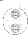
- FIG. 2 is a sectional view along an A-A line of FIG. 1 .
- tubes 12 are inserted into a shell (drum container) 11 of the heat exchanger 50.
- Fluid (first medium) 16 such as excess water vapor flows into the shell 11 through an inlet 13, flows between the inside of the shell 11 and the outside of the tubes 12, and flows out through an outlet 15.
- Coolant (second medium) 14 such as water is injected into the tube 12 front one end thereof, and exchanges heat with the fluid 16 such as excess water vapor. Accordingly, the fluid 16 is cooled, and the coolant 14 itself is warmed.
- the tube 12 inserted into the shell 11 of the heat exchanger 50 includes double tubes of an inner tube 1a and an outer tube 1b, and a thermoelectric power generation module 2 is attached to the outer surface of the inner tube 1a preferably through a heat dissipation sheet 3a. Moreover, a heat dissipation sheet 3b is mounted between the thermoelectric power generation module 2 and the outer tube 1b.
- the coolant 14 flows in the inner tube 1a.
- Sheets with a high thermal conductivity are preferably used as the heat dissipation sheets 3a, 3b inserted between the inner tube 1a and the thermoelectric power generation module 2 and between the thermoelectric power generation module 2 and the outer tube 1b.
- the double tubes sandwiching the thermoelectric power generation module 2 may be produced in such a manner that the thermoelectric power generation module is wound around the inner tube 1a through the heat dissipation sheet 3a, e.g., a silicone rubber sheet having a thermal conductivity of 4 W/mK and a thickness of 1 mm, the heat dissipation sheet 3b is attached thereto, and the outer tube 1b is fitted thereon.
- the thermoelectric power generation module is wound around the inner tube 1a through the heat dissipation sheet 3a, e.g., a silicone rubber sheet having a thermal conductivity of 4 W/mK and a thickness of 1 mm, the heat dissipation sheet 3b is attached thereto, and the outer tube 1b is fitted thereon.
- the outer tube 1b can be easily fitted onto the heat dissipation sheet 3b. If seamless tubes, i.e., tubes with no joints, are used as the inner tube 1a and the outer tube 1b, a highly-reliable system having excellent pressure resistance and causing no leakage can be built.
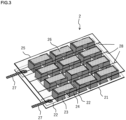
- FIG. 3 is a view showing a specific configuration of the thermoelectric power generation module 2.
- P-type thermoelectric devices 23 and N-type thermoelectric devices 24 are alternately arrayed and mounted on wiring lands 22 formed on a flexible base substrate 21.
- the P-type thermoelectric device 23 and the N-type thermoelectric device 24 are connected in series through a wiring layer 26 formed on a flexible upper wiring board 25.
- Generated thermoelectric power is taken out through lead-out electrodes 27.
- the upper wiring board 25 is formed with slits 28, each of which is formed between adjacent ones of the lines of the P-type thermoelectric devices 23 and the N-type thermoelectric devices 24 connected to each other.
- the module 2 is easily bendable in a direction at a right angle to the slit 28, and by aligning the slits 28 with a tube axis direction, the module 2 can easily closely contact the inner tube 1a.
- the flexible upper wiring board 25 is seen through for the sake of illustration of the state of lower chip mounting and wiring.
- thermoelectric power generation system 10 in the present embodiment is configured, for example, such that the inner tube 1a has an outer diameter of 25.4 mm, the thermoelectric power generation module 2 has a size of 10 cm square and a thickness of 1.2 mm, and the outer tube 1b has an outer diameter of 36 mm.
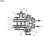
- FIG. 4 is a view showing a method for fixing the inner tube 1a and the outer tube 1b of the tube 12 and taking out the output of the thermoelectric power generation module 2 in the shell-and-tube heat exchanger 50.
- the inner tube 1a of the tube 12 is fixed to the shell 11 with an inner-tube fixing tube plate 31, and the outer tube 1b is fixed to the shell 11 with an outer-tube fixing tube plate 32.
- the output 33 of the thermoelectric power generation module 2 is taken out through a clearance between the inner-tube fixing tube plate 31 and the outer-tube fixing tube plate 32.
- FIG. 5 is a view showing the configuration of a thermoelectric power generation system including the shell-and-tube heat exchangers 50 having a thermoelectric power generation function using drainage hot water and drainage steam in geothermal power generation.
- a geothermal spring source 41 is pumped up from a production well 42, and is separated into steam 44a and hot water 44b in a steam-water separator 43.
- the steam 44a is introduced into a steam turbine 45, and generates power by rotating the turbine 45 and a power generator 47.
- drainage steam 49 from the steam turbine 45 is returned to water by a condenser, and together with the hot water 44b, is returned to the ground through a return well 46 in order to avoid depletion of the spring source. Thermal energy is wastefully discarded.
- thermoelectric power generation system of the present embodiment the hot water 44b and the drainage steam 49 are introduced into the thermoelectric power generation function-equipped shell-and-tube heat exchangers 50 shown in FIG. 2 to exchange heat with the coolant 14 and to generate thermoelectric power by the thermoelectric power generation modules (not shown) shown in FIG. 2 , as shown in FIG. 5 .
- waste energy can be effectively used.
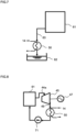
- FIG. 6 is a view showing the configuration of a thermoelectric power generation system including the shell-and-tube heat exchanger 50 having a thermoelectric power generation function using hot drainage water from a gas engine.
- Hot drainage water 52 from a gas engine 53 is introduced into the thermoelectric power generation function-equipped shell-and-tube heat exchanger 50 shown in FIG. 2 , is cooled by exchanging heat with the coolant 14, and is returned to the gas engine 53 by a pump 54.
- thermoelectric power is generated by the thermoelectric power generation module (not shown) shown in FIG. 2 .
- waste energy can be effectively used.
- FIG. 7 is a view showing the configuration of a thermoelectric power generation system including the shell-and-tube heat exchanger 50 having a thermoelectric power generation function using continuous blow hot drainage water from a boiler.
- thermoelectric power generation function-equipped shell-and-tube heat exchanger 50 shown in FIG. 2 is introduced into the thermoelectric power generation function-equipped shell-and-tube heat exchanger 50 shown in FIG. 2 , is cooled by exchanging heat with the coolant 14, and is discharged to a drainage tank 62.
- thermoelectric power is generated by the thermoelectric power generation module (not shown) shown in FIG. 2 .
- waste energy can be effectively used.
- FIG. 8 is a view showing the configuration of a thermoelectric power generation system including the shell-and-tube heat exchanger 50 having a thermoelectric power generation function using drainage steam from a steam turbine.
- a boiler 61 generates steam 44a to drive a steam turbine 45, and accordingly, a power generator 47 rotates to generate power. Drainage steam 49 from the steam turbine 45 is introduced into the thermoelectric power generation function-equipped shell-and-tube heat exchanger 50 shown in FIG. 2 , is cooled by exchanging heat with the coolant 14, and is returned to water, i.e., is condensed. The condensate is returned to the boiler 61 by a water supply pump 71. As described above, the heat exchanger 50 operates as a condenser, and thermoelectric power is generated by the thermoelectric power generation module (not shown) shown in FIG. 2 . Thus, waste energy can be effectively used.
- FIG. 9 is a view showing the configuration of a thermoelectric power generation system including the shell-and-tube heat exchanger 50 having a thermoelectric power generation function using flash steam from a boiler.
- An exhaust heat boiler 61a generates steam 88 to be used in a process.
- Raw water 87 stored in a water tank 85 is supplied to the exhaust heat boiler 61a by a water supply pump 86, and is preliminarily heated with exhaust heat discharged to an exhaust pipe 82 in an economizer 81.
- Part of the raw water 87 is sent to a flash tank 84, and generates hot water and flash steam.
- thermoelectric power generation function-equipped shell-and-tube heat exchanger 50 shown in FIG. 2 is cooled by exchanging heat with the coolant, is returned to water, and is returned to the water tank 85. Moreover, the coolant is warmed using the raw water 87 in the heat exchanger 50.
- the thermoelectric power generation module (not shown) shown in FIG. 2 generates thermoelectric power using a temperature difference between the steam and the raw water, and waste energy in this system can be effectively used.
- Valves 83a, 83b, 83c in the middle of the system are for adjusting a steam amount and a thermoelectric power generation amount in the system according to steam and power demands. For example, in the case of a great power demand and a small steam demand, the valves 83a, 83b are opened to increase the thermoelectric power generation amount. In the case of a small power demand and a great steam demand, the valves 83a, 83b are closed to increase the steam amount. In the case of a great power demand and an extremely-small steam demand, the valves 83a, 83b, 83c are opened to increase the thermoelectric power generation amount. As described above, variable thermoelectric power generation operation is allowed by opening/closing of the valves 83a, 83b, 83c.
Landscapes
- Engineering & Computer Science (AREA)
- Physics & Mathematics (AREA)
- Thermal Sciences (AREA)
- Mechanical Engineering (AREA)
- General Engineering & Computer Science (AREA)
- Heat-Exchange Devices With Radiators And Conduit Assemblies (AREA)
- Engine Equipment That Uses Special Cycles (AREA)
Abstract
Description
- The present invention relates to a thermoelectric power generation system using a shell-and-tube heat exchanger.
- In a current industrial society, mainly in a factory, an electric power plant, a steel plant, an automobile, a building, an illumination, a ship, etc., an enormous waste heat amount of 60% or more of the total primary energy supply amount has been discharged to global environment. It has been assumed that 75% or more of such waste heat is drainage water or exhaust gas at 250°C or lower. Such waste heat, e.g., drainage steam from a steam turbine, is recovered by a shell-and-tube heat exchanger. The drainage steam introduced into a shell (drum container) exchanges heat with, e.g., cold water flowing in a tube inserted into the shell.
- However, in a conventional shell-and-tube heat exchanger, drainage steam introduced into a shell can be cooled, but it is difficult to use hot water subjected to heat exchange in a tube. For this reason, recovered thermal energy is wasted, leading to a problem on energy saving.
- The present invention has been made in view of the above-described point, and a main object thereof is to provide a thermoelectric power generation system capable of producing easy-to-use electric energy from waste heat energy and effectively using the waste heat energy.
- A thermoelectric power generation system according to the present invention includes a shell-and-tube heat exchanger configured such that a tube including double tubes of an inner tube and an outer tube is inserted into a shell, and a thermoelectric power generation module inserted into between the inner tube and the outer tube. The thermoelectric power generation module generates thermoelectric power using a temperature difference between a first medium flowing in the inner tube and a second medium flowing outside the outer tube in the shell.
- In a preferred embodiment, the second medium flowing in the shell is drainage hot water and drainage steam in geothermal power generation, continuous blow hot drainage water from a boiler, flash steam from a boiler, drainage steam from a steam turbine, or drainage hot water or drainage steam from a gas engine.
- In a preferred embodiment, the tube includes a plurality of tubes inserted into the shell. An inner tube of each tube is fixed to the shell with an inner-tube fixing tube plate, and an outer tube of each tube is fixed to the shell with an outer-tube fixing tube plate. The output of the thermoelectric power generation module is taken out through a clearance between the inner-tube fixing tube plate and the outer-tube fixing tube plate.
- According to the present invention, a thermoelectric power generation system can be provided, which is capable of recovering thermal energy, which has not been recovered so far, by thermoelectric power generation to produce easy-to-use electric energy from waste heat energy and effectively use the waste heat energy.
-
- [
FIG. 1] FIG. 1 is a view schematically showing the configuration of a thermoelectric power generation system including a shell-and-tube heat exchanger according to one embodiment of the present invention. - [
FIG. 2] FIG. 2 is a sectional view along an A-A line ofFIG. 1 . - [
FIG. 3] FIG. 3 is a view showing a specific configuration of a thermoelectric power generation module in the present invention. - [
FIG. 4] FIG. 4 is a view showing a method for fixing an inner tube and an outer tube of a tube and taking out the output of the thermoelectric power generation module in the shell-and-tube heat exchanger. - [
FIG. 5] FIG. 5 is a view showing the configuration of a thermoelectric power generation system including shell-and-tube heat exchangers having a thermoelectric power generation function in another embodiment of the present invention. - [
FIG. 6] FIG. 6 is a view showing the configuration of a thermoelectric power generation system including a shell-and-tube heat exchanger having a thermoelectric power generation function in still another embodiment of the present invention. - [
FIG. 7] FIG. 7 is a view showing the configuration of a thermoelectric power generation system including a shell-and-tube heat exchanger having a thermoelectric power generation function in still another embodiment of the present invention. - [
FIG. 8] FIG. 8 is a view showing the configuration of a thermoelectric power generation system including a shell-and-tube heat exchanger having a thermoelectric power generation function in still another embodiment of the present invention. - [
FIG. 9] FIG. 9 is a view showing the configuration of a thermoelectric power generation system including a shell-and-tube heat exchanger having a thermoelectric power generation function in still another embodiment of the present invention. - Hereinafter, an embodiment of the present invention will be described in detail based on the drawings. Note that the present invention is not limited to the following embodiment. Moreover, changes can be made as necessary without departing from a scope in which advantageous effects of the present invention can be provided.
-
FIGS. 1 and2 are views schematically showing the configuration of a thermoelectricpower generation system 10 including a shell-and-tube heat exchanger 50 according to one embodiment of the present invention.FIG. 2 is a sectional view along an A-A line ofFIG. 1 . - As shown in
FIGS. 1 and2 , tubes 12 (two in the figure) are inserted into a shell (drum container) 11 of theheat exchanger 50. Fluid (first medium) 16 such as excess water vapor flows into theshell 11 through aninlet 13, flows between the inside of theshell 11 and the outside of thetubes 12, and flows out through anoutlet 15. Coolant (second medium) 14 such as water is injected into thetube 12 front one end thereof, and exchanges heat with thefluid 16 such as excess water vapor. Accordingly, thefluid 16 is cooled, and thecoolant 14 itself is warmed. - As shown in
FIG. 2 , thetube 12 inserted into theshell 11 of theheat exchanger 50 includes double tubes of an inner tube 1a and anouter tube 1b, and a thermoelectricpower generation module 2 is attached to the outer surface of the inner tube 1a preferably through a heat dissipation sheet 3a. Moreover, aheat dissipation sheet 3b is mounted between the thermoelectricpower generation module 2 and theouter tube 1b. Thecoolant 14 flows in the inner tube 1a. - Sheets with a high thermal conductivity are preferably used as the
heat dissipation sheets 3a, 3b inserted between the inner tube 1a and the thermoelectricpower generation module 2 and between the thermoelectricpower generation module 2 and theouter tube 1b. With this configuration, adhesion between the thermoelectricpower generation module 2 and each of the inner tube 1a and theouter tube 1b can be ensured, and a heat transfer loss can be reduced. As a result, a great temperature difference in the thermoelectricpower generation module 2 can be ensured, and a thermoelectric power generation efficiency can be improved. - The double tubes sandwiching the thermoelectric
power generation module 2 may be produced in such a manner that the thermoelectric power generation module is wound around the inner tube 1a through the heat dissipation sheet 3a, e.g., a silicone rubber sheet having a thermal conductivity of 4 W/mK and a thickness of 1 mm, theheat dissipation sheet 3b is attached thereto, and theouter tube 1b is fitted thereon. - If a carbon sheet having a thermal conductivity of 30 W/mK is used as the
heat dissipation sheet 3b, heat transfer and slipperiness can be improved, and therefore, theouter tube 1b can be easily fitted onto theheat dissipation sheet 3b. If seamless tubes, i.e., tubes with no joints, are used as the inner tube 1a and theouter tube 1b, a highly-reliable system having excellent pressure resistance and causing no leakage can be built. -
FIG. 3 is a view showing a specific configuration of the thermoelectricpower generation module 2. As shown inFIG. 3 , P-typethermoelectric devices 23 and N-typethermoelectric devices 24 are alternately arrayed and mounted onwiring lands 22 formed on aflexible base substrate 21. The P-typethermoelectric device 23 and the N-typethermoelectric device 24 are connected in series through awiring layer 26 formed on a flexibleupper wiring board 25. Generated thermoelectric power is taken out through lead-outelectrodes 27. - The
upper wiring board 25 is formed withslits 28, each of which is formed between adjacent ones of the lines of the P-typethermoelectric devices 23 and the N-typethermoelectric devices 24 connected to each other. With this configuration, themodule 2 is easily bendable in a direction at a right angle to theslit 28, and by aligning theslits 28 with a tube axis direction, themodule 2 can easily closely contact the inner tube 1a. Note that in this figure, the flexibleupper wiring board 25 is seen through for the sake of illustration of the state of lower chip mounting and wiring. - The thermoelectric
power generation system 10 in the present embodiment is configured, for example, such that the inner tube 1a has an outer diameter of 25.4 mm, the thermoelectricpower generation module 2 has a size of 10 cm square and a thickness of 1.2 mm, and theouter tube 1b has an outer diameter of 36 mm. -
FIG. 4 is a view showing a method for fixing the inner tube 1a and theouter tube 1b of thetube 12 and taking out the output of the thermoelectricpower generation module 2 in the shell-and-tube heat exchanger 50. - As shown in
FIG. 4 , the inner tube 1a of thetube 12 is fixed to theshell 11 with an inner-tubefixing tube plate 31, and theouter tube 1b is fixed to theshell 11 with an outer-tubefixing tube plate 32. Theoutput 33 of the thermoelectricpower generation module 2 is taken out through a clearance between the inner-tubefixing tube plate 31 and the outer-tubefixing tube plate 32. -
FIG. 5 is a view showing the configuration of a thermoelectric power generation system including the shell-and-tube heat exchangers 50 having a thermoelectric power generation function using drainage hot water and drainage steam in geothermal power generation. - In geothermal power generation, a
geothermal spring source 41 is pumped up from a production well 42, and is separated intosteam 44a andhot water 44b in a steam-water separator 43. Thesteam 44a is introduced into asteam turbine 45, and generates power by rotating theturbine 45 and apower generator 47. - In normal geothermal power generation,
drainage steam 49 from thesteam turbine 45 is returned to water by a condenser, and together with thehot water 44b, is returned to the ground through a return well 46 in order to avoid depletion of the spring source. Thermal energy is wastefully discarded. - However, in the thermoelectric power generation system of the present embodiment, the
hot water 44b and thedrainage steam 49 are introduced into the thermoelectric power generation function-equipped shell-and-tube heat exchangers 50 shown inFIG. 2 to exchange heat with thecoolant 14 and to generate thermoelectric power by the thermoelectric power generation modules (not shown) shown inFIG. 2 , as shown inFIG. 5 . Thus, waste energy can be effectively used. -
FIG. 6 is a view showing the configuration of a thermoelectric power generation system including the shell-and-tube heat exchanger 50 having a thermoelectric power generation function using hot drainage water from a gas engine. -
Hot drainage water 52 from agas engine 53 is introduced into the thermoelectric power generation function-equipped shell-and-tube heat exchanger 50 shown inFIG. 2 , is cooled by exchanging heat with thecoolant 14, and is returned to thegas engine 53 by apump 54. In addition, thermoelectric power is generated by the thermoelectric power generation module (not shown) shown inFIG. 2 . Thus, waste energy can be effectively used. -
FIG. 7 is a view showing the configuration of a thermoelectric power generation system including the shell-and-tube heat exchanger 50 having a thermoelectric power generation function using continuous blow hot drainage water from a boiler. - In order to prevent, e.g., impurity accumulation, maintenance is regularly performed for a
boiler 61 to discharge continuous blowhot drainage water 63. The continuous blowhot drainage water 63 is introduced into the thermoelectric power generation function-equipped shell-and-tube heat exchanger 50 shown inFIG. 2 , is cooled by exchanging heat with thecoolant 14, and is discharged to adrainage tank 62. In addition, thermoelectric power is generated by the thermoelectric power generation module (not shown) shown inFIG. 2 . Thus, waste energy can be effectively used. -
FIG. 8 is a view showing the configuration of a thermoelectric power generation system including the shell-and-tube heat exchanger 50 having a thermoelectric power generation function using drainage steam from a steam turbine. - A
boiler 61 generatessteam 44a to drive asteam turbine 45, and accordingly, apower generator 47 rotates to generate power.Drainage steam 49 from thesteam turbine 45 is introduced into the thermoelectric power generation function-equipped shell-and-tube heat exchanger 50 shown inFIG. 2 , is cooled by exchanging heat with thecoolant 14, and is returned to water, i.e., is condensed. The condensate is returned to theboiler 61 by awater supply pump 71. As described above, theheat exchanger 50 operates as a condenser, and thermoelectric power is generated by the thermoelectric power generation module (not shown) shown inFIG. 2 . Thus, waste energy can be effectively used. -
FIG. 9 is a view showing the configuration of a thermoelectric power generation system including the shell-and-tube heat exchanger 50 having a thermoelectric power generation function using flash steam from a boiler. - An
exhaust heat boiler 61a generatessteam 88 to be used in a process.Raw water 87 stored in awater tank 85 is supplied to theexhaust heat boiler 61a by awater supply pump 86, and is preliminarily heated with exhaust heat discharged to anexhaust pipe 82 in aneconomizer 81. Part of theraw water 87 is sent to aflash tank 84, and generates hot water and flash steam. - The flash steam is introduced into the thermoelectric power generation function-equipped shell-and-
tube heat exchanger 50 shown inFIG. 2 , is cooled by exchanging heat with the coolant, is returned to water, and is returned to thewater tank 85. Moreover, the coolant is warmed using theraw water 87 in theheat exchanger 50. Thus, the thermoelectric power generation module (not shown) shown inFIG. 2 generates thermoelectric power using a temperature difference between the steam and the raw water, and waste energy in this system can be effectively used. -
Valves valves valves valves valves - The present invention has been described above with reference to the preferred embodiments, but is not limited to description of these embodiments. Needless to say, various modifications can be made.
-
- 1a
- Inner Tube
- 1b
- Outer Tube
- 2
- Thermoelectric Power Generation Module
- 3a, 3b
- Heat Dissipation Sheet
- 10
- Thermoelectric Power Generation System
- 11
- Shell
- 12
- Tube
- 13
- Inlet of Shell-Side Fluid
- 14
- Coolant (First Medium)
- 15
- Outlet of Shell-Side Fluid
- 16
- Fluid (Second Medium)
- 21
- Base Substrate
- 22
- Wiring Land
- 23
- P-Type Thermoelectric Device
- 24
- N-Type Thermoelectric Device
- 25
- Upper Wiring Board
- 26
- Wiring Layer
- 27
- Electrode
- 28
- Slit
- 31
- Inner-Tube Fixing Tube Plate
- 32
- Outer-Tube Fixing Tube Plate
- 33
- Output of Thermoelectric Power Generation Module
- 41
- Geothermal Spring Source
- 42
- Production Well
- 43
- Steam-Water Separator
- 44a
- Steam
- 44b
- Hot Water
- 45
- Steam Turbine
- 46
- Return Well
- 47
- Power Generator
- 48
- Condenser
- 49
- Drainage Steam
- 50
- (Thermoelectric Power Generation Function-Equipped) Shell-and-Tube Heat Exchanger
- 52
- Hot Drainage Water
- 53
- Gas Engine
- 54
- Pump
- 61
- Boiler
- 61a
- Exhaust Heat Boiler
- 62
- Drainage Tank
- 63
- Continuous Blow Hot Drainage Water
- 71, 86
- Water Supply Pump
- 81
- Economizer
- 82
- Exhaust Pipe
- 83a, 83b, 83c
- Valve
- 84
- Flash Tank
- 85
- Water Tank
- 87
- Raw Water
- 88
- Process Steam
Claims (6)
- A thermoelectric power generation system comprising:a shell-and-tube heat exchanger configured such that a tube including double tubes of an inner tube and an outer tube is inserted into a shell; anda thermoelectric power generation module inserted into between the inner tube and the outer tube,wherein the thermoelectric power generation module generates thermoelectric power using a temperature difference between a first medium flowing in the inner tube and a second medium flowing outside the outer tube in the shell.
- The thermoelectric power generation system of claim 1, wherein
the first medium flowing in the inner tube is coolant, and the second medium flowing in the shell is water vapor. - The thermoelectric power generation system of claim 1 or 2, wherein
the second medium flowing in the shell is any one selected from drainage hot water and drainage steam in geothermal power generation, continuous blow hot drainage water from a boiler, flash steam from a boiler, drainage steam from a steam turbine, and drainage hot water or drainage steam from a gas engine. - The thermoelectric power generation system of any one of claims 1 to 3, wherein
a heat dissipation sheet is inserted into between the thermoelectric power generation module and the outer tube. - The thermoelectric power generation system of any one of claims 1 to 4, wherein
the double tubes are seamless tubes. - The thermoelectric power generation system of any one of claims 1 to 5, whereinthe tube includes a plurality of tubes inserted into the shell,an inner tube of each tube is fixed to the shell with an inner-tube fixing tube plate, and an outer tube of each tube is fixed to the shell with an outer-tube fixing tube plate, andan output of the thermoelectric power generation module is taken out through a clearance between the inner-tube fixing tube plate and the outer-tube fixing tube plate.
Applications Claiming Priority (2)
| Application Number | Priority Date | Filing Date | Title |
|---|---|---|---|
| JP2021062772 | 2021-04-01 | ||
| PCT/JP2022/014644 WO2022210416A1 (en) | 2021-04-01 | 2022-03-25 | Thermoelectric power generation system |
Publications (3)
| Publication Number | Publication Date |
|---|---|
| EP4318929A1 true EP4318929A1 (en) | 2024-02-07 |
| EP4318929A4 EP4318929A4 (en) | 2024-09-18 |
| EP4318929B1 EP4318929B1 (en) | 2025-11-26 |
Family
ID=83456216
Family Applications (1)
| Application Number | Title | Priority Date | Filing Date |
|---|---|---|---|
| EP22780629.6A Active EP4318929B1 (en) | 2021-04-01 | 2022-03-25 | Thermoelectric power generation system |
Country Status (4)
| Country | Link |
|---|---|
| US (1) | US20240180035A1 (en) |
| EP (1) | EP4318929B1 (en) |
| JP (1) | JPWO2022210416A1 (en) |
| WO (1) | WO2022210416A1 (en) |
Family Cites Families (11)
| Publication number | Priority date | Publication date | Assignee | Title |
|---|---|---|---|---|
| US3054840A (en) * | 1958-05-06 | 1962-09-18 | Westinghouse Electric Corp | Thermopile |
| JPS59161662U (en) * | 1983-04-15 | 1984-10-29 | 日産自動車株式会社 | thermoelectric conversion device |
| DE102008058779A1 (en) * | 2008-11-24 | 2010-05-27 | Emitec Gesellschaft Für Emissionstechnologie Mbh | Module for a thermoelectric generator and a thermoelectric generator |
| DE102009058676A1 (en) * | 2009-12-16 | 2011-06-22 | Behr GmbH & Co. KG, 70469 | heat exchangers |
| JP2013165240A (en) * | 2012-02-13 | 2013-08-22 | Central Research Institute Of Electric Power Industry | Thermoelectric conversion system |
| JP2015524894A (en) * | 2012-08-01 | 2015-08-27 | ゲンサーム インコーポレイテッド | High efficiency thermoelectric power generation |
| JP6064591B2 (en) * | 2012-12-27 | 2017-01-25 | トヨタ自動車株式会社 | Thermoelectric generator |
| JP5866533B2 (en) * | 2013-03-12 | 2016-02-17 | パナソニックIpマネジメント株式会社 | Thermoelectric generator unit, thermoelectric generator system and thermoelectric generator module |
| DE102014201908A1 (en) * | 2014-02-03 | 2015-08-06 | Duerr Cyplan Ltd. | Method for guiding a fluid flow, flow apparatus and its use |
| JP6237345B2 (en) * | 2014-03-03 | 2017-11-29 | トヨタ自動車株式会社 | Thermoelectric generator |
| JP7054160B2 (en) * | 2017-08-30 | 2022-04-13 | 株式会社Eサーモジェンテック | Thermoelectric power generation system |
-
2022
- 2022-03-25 JP JP2023511199A patent/JPWO2022210416A1/ja active Pending
- 2022-03-25 US US18/284,230 patent/US20240180035A1/en active Pending
- 2022-03-25 EP EP22780629.6A patent/EP4318929B1/en active Active
- 2022-03-25 WO PCT/JP2022/014644 patent/WO2022210416A1/en not_active Ceased
Also Published As
| Publication number | Publication date |
|---|---|
| EP4318929A4 (en) | 2024-09-18 |
| WO2022210416A1 (en) | 2022-10-06 |
| JPWO2022210416A1 (en) | 2022-10-06 |
| US20240180035A1 (en) | 2024-05-30 |
| EP4318929B1 (en) | 2025-11-26 |
Similar Documents
| Publication | Publication Date | Title |
|---|---|---|
| RU2483265C2 (en) | General-purpose recuperator assembly for waste gases of gas turbine | |
| US10030566B2 (en) | Waste energy recovery system utilizing modular heat exchanger and conversion system | |
| US8708035B2 (en) | Heat exchanger in a modular construction | |
| CN110691953B (en) | Heat Exchangers for Molten Salt Steam Generators in Concentrated Solar Power Plants | |
| JP2008255822A (en) | Combined cycle power generation plant and heat exchanger | |
| US20030015316A1 (en) | Heat exchange tube having increased heat transfer area | |
| EP4318929B1 (en) | Thermoelectric power generation system | |
| WO2010038288A1 (en) | Combined cycle electric power generation plant and heat exchanger | |
| US20100095648A1 (en) | Combined Cycle Power Plant | |
| NO20180376A1 (en) | A system for recovery of waste heat from an industrial plant | |
| JP2025168560A (en) | Method for manufacturing a thermoelectric power generation system | |
| EP2423473B1 (en) | An improved organic rankine cycle system and method | |
| BR112020024555A2 (en) | ELECTRIC POWER PLANT WITH REGASIFICATION OF NATURAL GAS | |
| US20160216040A1 (en) | Heat exchanger | |
| WO2017176239A1 (en) | Heat exchanger | |
| CN220648299U (en) | ORC is with taking cooling hot water circulation system | |
| KR101249188B1 (en) | thermal energy conversion apparatus for independent and parallel operation | |
| CN212565943U (en) | Low-pressure cylinder zero-power improved heat supply network heater | |
| CN221483701U (en) | A heating device and seawater desalination system based on cascade utilization of steam energy | |
| KR200284930Y1 (en) | Apparatus for recovering waste-heat of exhaust gas through a flue duct of boiler | |
| CN223610656U (en) | Waste heat recovery heat exchanger | |
| CN212378571U (en) | Semi-spiral tube type superconducting heat pipe | |
| JP2000186549A (en) | Engine cooling system | |
| EP2917514B1 (en) | A cooling arrangement for a combined cycle internal combustion piston engine power plant | |
| KR20170114391A (en) | System for recycling wasted heat of vessel |
Legal Events
| Date | Code | Title | Description |
|---|---|---|---|
| STAA | Information on the status of an ep patent application or granted ep patent |
Free format text: STATUS: THE INTERNATIONAL PUBLICATION HAS BEEN MADE |
|
| PUAI | Public reference made under article 153(3) epc to a published international application that has entered the european phase |
Free format text: ORIGINAL CODE: 0009012 |
|
| STAA | Information on the status of an ep patent application or granted ep patent |
Free format text: STATUS: REQUEST FOR EXAMINATION WAS MADE |
|
| 17P | Request for examination filed |
Effective date: 20230912 |
|
| AK | Designated contracting states |
Kind code of ref document: A1 Designated state(s): AL AT BE BG CH CY CZ DE DK EE ES FI FR GB GR HR HU IE IS IT LI LT LU LV MC MK MT NL NO PL PT RO RS SE SI SK SM TR |
|
| DAV | Request for validation of the european patent (deleted) | ||
| DAX | Request for extension of the european patent (deleted) | ||
| REG | Reference to a national code |
Ref country code: DE Ref legal event code: R079 Free format text: PREVIOUS MAIN CLASS: H02N0011000000 Ref country code: DE Ref legal event code: R079 Ref document number: 602022025735 Country of ref document: DE Free format text: PREVIOUS MAIN CLASS: H02N0011000000 Ipc: F28D0007160000 |
|
| A4 | Supplementary search report drawn up and despatched |
Effective date: 20240819 |
|
| RIC1 | Information provided on ipc code assigned before grant |
Ipc: H10N 10/13 20230101ALI20240812BHEP Ipc: F28D 7/10 20060101ALI20240812BHEP Ipc: H02N 11/00 20060101ALI20240812BHEP Ipc: F28D 7/16 20060101AFI20240812BHEP |
|
| GRAP | Despatch of communication of intention to grant a patent |
Free format text: ORIGINAL CODE: EPIDOSNIGR1 |
|
| STAA | Information on the status of an ep patent application or granted ep patent |
Free format text: STATUS: GRANT OF PATENT IS INTENDED |
|
| INTG | Intention to grant announced |
Effective date: 20250623 |
|
| GRAS | Grant fee paid |
Free format text: ORIGINAL CODE: EPIDOSNIGR3 |
|
| GRAA | (expected) grant |
Free format text: ORIGINAL CODE: 0009210 |
|
| STAA | Information on the status of an ep patent application or granted ep patent |
Free format text: STATUS: THE PATENT HAS BEEN GRANTED |
|
| RAP3 | Party data changed (applicant data changed or rights of an application transferred) |
Owner name: E-THERMOGENTEK CO. LTD. Owner name: KAWASAKI JUKOGYO KABUSHIKI KAISHA Owner name: KAWASAKI THERMAL ENGINEERING CO., LTD. |
|
| AK | Designated contracting states |
Kind code of ref document: B1 Designated state(s): AL AT BE BG CH CY CZ DE DK EE ES FI FR GB GR HR HU IE IS IT LI LT LU LV MC MK MT NL NO PL PT RO RS SE SI SK SM TR |
|
| REG | Reference to a national code |
Ref country code: CH Ref legal event code: F10 Free format text: ST27 STATUS EVENT CODE: U-0-0-F10-F00 (AS PROVIDED BY THE NATIONAL OFFICE) Effective date: 20251126 Ref country code: GB Ref legal event code: FG4D |
|
| REG | Reference to a national code |
Ref country code: IE Ref legal event code: FG4D |
|
| REG | Reference to a national code |
Ref country code: DE Ref legal event code: R096 Ref document number: 602022025735 Country of ref document: DE |
|
| P01 | Opt-out of the competence of the unified patent court (upc) registered |
Free format text: CASE NUMBER: UPC_APP_0015496_4318929/2025 Effective date: 20251202 |
|
| REG | Reference to a national code |
Ref country code: NL Ref legal event code: MP Effective date: 20251126 |
|
| PG25 | Lapsed in a contracting state [announced via postgrant information from national office to epo] |
Ref country code: ES Free format text: LAPSE BECAUSE OF FAILURE TO SUBMIT A TRANSLATION OF THE DESCRIPTION OR TO PAY THE FEE WITHIN THE PRESCRIBED TIME-LIMIT Effective date: 20251126 |
|
| REG | Reference to a national code |
Ref country code: LT Ref legal event code: MG9D |
|
| PG25 | Lapsed in a contracting state [announced via postgrant information from national office to epo] |
Ref country code: NO Free format text: LAPSE BECAUSE OF FAILURE TO SUBMIT A TRANSLATION OF THE DESCRIPTION OR TO PAY THE FEE WITHIN THE PRESCRIBED TIME-LIMIT Effective date: 20260226 |
|
| PGFP | Annual fee paid to national office [announced via postgrant information from national office to epo] |
Ref country code: DE Payment date: 20260319 Year of fee payment: 5 |
|
| PG25 | Lapsed in a contracting state [announced via postgrant information from national office to epo] |
Ref country code: FI Free format text: LAPSE BECAUSE OF FAILURE TO SUBMIT A TRANSLATION OF THE DESCRIPTION OR TO PAY THE FEE WITHIN THE PRESCRIBED TIME-LIMIT Effective date: 20251126 Ref country code: HR Free format text: LAPSE BECAUSE OF FAILURE TO SUBMIT A TRANSLATION OF THE DESCRIPTION OR TO PAY THE FEE WITHIN THE PRESCRIBED TIME-LIMIT Effective date: 20251126 Ref country code: AT Free format text: LAPSE BECAUSE OF FAILURE TO SUBMIT A TRANSLATION OF THE DESCRIPTION OR TO PAY THE FEE WITHIN THE PRESCRIBED TIME-LIMIT Effective date: 20251126 |
|
| PGFP | Annual fee paid to national office [announced via postgrant information from national office to epo] |
Ref country code: AT Payment date: 20260301 Year of fee payment: 5 |
|
| REG | Reference to a national code |
Ref country code: AT Ref legal event code: MK05 Ref document number: 1861432 Country of ref document: AT Kind code of ref document: T Effective date: 20251126 |
|
| PG25 | Lapsed in a contracting state [announced via postgrant information from national office to epo] |
Ref country code: NL Free format text: LAPSE BECAUSE OF FAILURE TO SUBMIT A TRANSLATION OF THE DESCRIPTION OR TO PAY THE FEE WITHIN THE PRESCRIBED TIME-LIMIT Effective date: 20251126 |
|
| PG25 | Lapsed in a contracting state [announced via postgrant information from national office to epo] |
Ref country code: RS Free format text: LAPSE BECAUSE OF FAILURE TO SUBMIT A TRANSLATION OF THE DESCRIPTION OR TO PAY THE FEE WITHIN THE PRESCRIBED TIME-LIMIT Effective date: 20260226 |
|
| PG25 | Lapsed in a contracting state [announced via postgrant information from national office to epo] |
Ref country code: IS Free format text: LAPSE BECAUSE OF FAILURE TO SUBMIT A TRANSLATION OF THE DESCRIPTION OR TO PAY THE FEE WITHIN THE PRESCRIBED TIME-LIMIT Effective date: 20260326 |
|
| PG25 | Lapsed in a contracting state [announced via postgrant information from national office to epo] |
Ref country code: PT Free format text: LAPSE BECAUSE OF FAILURE TO SUBMIT A TRANSLATION OF THE DESCRIPTION OR TO PAY THE FEE WITHIN THE PRESCRIBED TIME-LIMIT Effective date: 20260326 |
|
| PG25 | Lapsed in a contracting state [announced via postgrant information from national office to epo] |
Ref country code: PL Free format text: LAPSE BECAUSE OF FAILURE TO SUBMIT A TRANSLATION OF THE DESCRIPTION OR TO PAY THE FEE WITHIN THE PRESCRIBED TIME-LIMIT Effective date: 20251126 |
|
| PG25 | Lapsed in a contracting state [announced via postgrant information from national office to epo] |
Ref country code: LV Free format text: LAPSE BECAUSE OF FAILURE TO SUBMIT A TRANSLATION OF THE DESCRIPTION OR TO PAY THE FEE WITHIN THE PRESCRIBED TIME-LIMIT Effective date: 20251126 |
|
| PG25 | Lapsed in a contracting state [announced via postgrant information from national office to epo] |
Ref country code: BG Free format text: LAPSE BECAUSE OF FAILURE TO SUBMIT A TRANSLATION OF THE DESCRIPTION OR TO PAY THE FEE WITHIN THE PRESCRIBED TIME-LIMIT Effective date: 20251126 |
|
| PG25 | Lapsed in a contracting state [announced via postgrant information from national office to epo] |
Ref country code: LT Free format text: LAPSE BECAUSE OF FAILURE TO SUBMIT A TRANSLATION OF THE DESCRIPTION OR TO PAY THE FEE WITHIN THE PRESCRIBED TIME-LIMIT Effective date: 20251126 |
|
| PG25 | Lapsed in a contracting state [announced via postgrant information from national office to epo] |
Ref country code: SM Free format text: LAPSE BECAUSE OF FAILURE TO SUBMIT A TRANSLATION OF THE DESCRIPTION OR TO PAY THE FEE WITHIN THE PRESCRIBED TIME-LIMIT Effective date: 20251126 |
|
| PG25 | Lapsed in a contracting state [announced via postgrant information from national office to epo] |
Ref country code: DK Free format text: LAPSE BECAUSE OF FAILURE TO SUBMIT A TRANSLATION OF THE DESCRIPTION OR TO PAY THE FEE WITHIN THE PRESCRIBED TIME-LIMIT Effective date: 20251126 |
|
| PG25 | Lapsed in a contracting state [announced via postgrant information from national office to epo] |
Ref country code: IT Free format text: LAPSE BECAUSE OF FAILURE TO SUBMIT A TRANSLATION OF THE DESCRIPTION OR TO PAY THE FEE WITHIN THE PRESCRIBED TIME-LIMIT Effective date: 20251126 |
|
| PG25 | Lapsed in a contracting state [announced via postgrant information from national office to epo] |
Ref country code: EE Free format text: LAPSE BECAUSE OF FAILURE TO SUBMIT A TRANSLATION OF THE DESCRIPTION OR TO PAY THE FEE WITHIN THE PRESCRIBED TIME-LIMIT Effective date: 20251126 |
|
| PG25 | Lapsed in a contracting state [announced via postgrant information from national office to epo] |
Ref country code: CZ Free format text: LAPSE BECAUSE OF FAILURE TO SUBMIT A TRANSLATION OF THE DESCRIPTION OR TO PAY THE FEE WITHIN THE PRESCRIBED TIME-LIMIT Effective date: 20251126 |
|
| PG25 | Lapsed in a contracting state [announced via postgrant information from national office to epo] |
Ref country code: SK Free format text: LAPSE BECAUSE OF FAILURE TO SUBMIT A TRANSLATION OF THE DESCRIPTION OR TO PAY THE FEE WITHIN THE PRESCRIBED TIME-LIMIT Effective date: 20251126 |
|
| PG25 | Lapsed in a contracting state [announced via postgrant information from national office to epo] |
Ref country code: SE Free format text: LAPSE BECAUSE OF FAILURE TO SUBMIT A TRANSLATION OF THE DESCRIPTION OR TO PAY THE FEE WITHIN THE PRESCRIBED TIME-LIMIT Effective date: 20251126 |