EP4318841A2 - Power supply system - Google Patents
Power supply system Download PDFInfo
- Publication number
- EP4318841A2 EP4318841A2 EP23180967.4A EP23180967A EP4318841A2 EP 4318841 A2 EP4318841 A2 EP 4318841A2 EP 23180967 A EP23180967 A EP 23180967A EP 4318841 A2 EP4318841 A2 EP 4318841A2
- Authority
- EP
- European Patent Office
- Prior art keywords
- sub
- load unit
- voltage
- power supply
- unit
- Prior art date
- Legal status (The legal status is an assumption and is not a legal conclusion. Google has not performed a legal analysis and makes no representation as to the accuracy of the status listed.)
- Pending
Links
Images

Classifications
-
- H—ELECTRICITY
- H02—GENERATION; CONVERSION OR DISTRIBUTION OF ELECTRIC POWER
- H02M—APPARATUS FOR CONVERSION BETWEEN AC AND AC, BETWEEN AC AND DC, OR BETWEEN DC AND DC, AND FOR USE WITH MAINS OR SIMILAR POWER SUPPLY SYSTEMS; CONVERSION OF DC OR AC INPUT POWER INTO SURGE OUTPUT POWER; CONTROL OR REGULATION THEREOF
- H02M1/00—Details of apparatus for conversion
- H02M1/0048—Circuits or arrangements for reducing losses
-
- H—ELECTRICITY
- H02—GENERATION; CONVERSION OR DISTRIBUTION OF ELECTRIC POWER
- H02J—ELECTRIC POWER NETWORKS; CIRCUIT ARRANGEMENTS OR SYSTEMS FOR SUPPLYING OR DISTRIBUTING ELECTRIC POWER; SYSTEMS FOR STORING ELECTRIC ENERGY
- H02J1/00—Circuit arrangements for DC mains or DC distribution networks
- H02J1/10—Parallel operation of DC sources
- H02J1/102—Parallel operation of DC sources being switching converters
-
- H—ELECTRICITY
- H02—GENERATION; CONVERSION OR DISTRIBUTION OF ELECTRIC POWER
- H02J—ELECTRIC POWER NETWORKS; CIRCUIT ARRANGEMENTS OR SYSTEMS FOR SUPPLYING OR DISTRIBUTING ELECTRIC POWER; SYSTEMS FOR STORING ELECTRIC ENERGY
- H02J1/00—Circuit arrangements for DC mains or DC distribution networks
- H02J1/001—Hot plugging or unplugging of load or power modules to or from power distribution networks
-
- H—ELECTRICITY
- H02—GENERATION; CONVERSION OR DISTRIBUTION OF ELECTRIC POWER
- H02M—APPARATUS FOR CONVERSION BETWEEN AC AND AC, BETWEEN AC AND DC, OR BETWEEN DC AND DC, AND FOR USE WITH MAINS OR SIMILAR POWER SUPPLY SYSTEMS; CONVERSION OF DC OR AC INPUT POWER INTO SURGE OUTPUT POWER; CONTROL OR REGULATION THEREOF
- H02M1/00—Details of apparatus for conversion
- H02M1/0067—Converter structures employing plural converter units, other than for parallel operation of the units on a single load
-
- H—ELECTRICITY
- H02—GENERATION; CONVERSION OR DISTRIBUTION OF ELECTRIC POWER
- H02M—APPARATUS FOR CONVERSION BETWEEN AC AND AC, BETWEEN AC AND DC, OR BETWEEN DC AND DC, AND FOR USE WITH MAINS OR SIMILAR POWER SUPPLY SYSTEMS; CONVERSION OF DC OR AC INPUT POWER INTO SURGE OUTPUT POWER; CONTROL OR REGULATION THEREOF
- H02M1/00—Details of apparatus for conversion
- H02M1/0067—Converter structures employing plural converter units, other than for parallel operation of the units on a single load
- H02M1/007—Plural converter units in cascade
-
- H—ELECTRICITY
- H02—GENERATION; CONVERSION OR DISTRIBUTION OF ELECTRIC POWER
- H02M—APPARATUS FOR CONVERSION BETWEEN AC AND AC, BETWEEN AC AND DC, OR BETWEEN DC AND DC, AND FOR USE WITH MAINS OR SIMILAR POWER SUPPLY SYSTEMS; CONVERSION OF DC OR AC INPUT POWER INTO SURGE OUTPUT POWER; CONTROL OR REGULATION THEREOF
- H02M3/00—Conversion of DC power input into DC power output
- H02M3/02—Conversion of DC power input into DC power output without intermediate conversion into AC
- H02M3/04—Conversion of DC power input into DC power output without intermediate conversion into AC by static converters
- H02M3/10—Conversion of DC power input into DC power output without intermediate conversion into AC by static converters using discharge tubes with control electrode or semiconductor devices with control electrode
- H02M3/145—Conversion of DC power input into DC power output without intermediate conversion into AC by static converters using discharge tubes with control electrode or semiconductor devices with control electrode using devices of a triode or transistor type requiring continuous application of a control signal
- H02M3/155—Conversion of DC power input into DC power output without intermediate conversion into AC by static converters using discharge tubes with control electrode or semiconductor devices with control electrode using devices of a triode or transistor type requiring continuous application of a control signal using semiconductor devices only
- H02M3/156—Conversion of DC power input into DC power output without intermediate conversion into AC by static converters using discharge tubes with control electrode or semiconductor devices with control electrode using devices of a triode or transistor type requiring continuous application of a control signal using semiconductor devices only with automatic control of output voltage or current, e.g. switching regulators
- H02M3/158—Conversion of DC power input into DC power output without intermediate conversion into AC by static converters using discharge tubes with control electrode or semiconductor devices with control electrode using devices of a triode or transistor type requiring continuous application of a control signal using semiconductor devices only with automatic control of output voltage or current, e.g. switching regulators including plural semiconductor devices as final control devices for a single load
-
- H—ELECTRICITY
- H02—GENERATION; CONVERSION OR DISTRIBUTION OF ELECTRIC POWER
- H02M—APPARATUS FOR CONVERSION BETWEEN AC AND AC, BETWEEN AC AND DC, OR BETWEEN DC AND DC, AND FOR USE WITH MAINS OR SIMILAR POWER SUPPLY SYSTEMS; CONVERSION OF DC OR AC INPUT POWER INTO SURGE OUTPUT POWER; CONTROL OR REGULATION THEREOF
- H02M1/00—Details of apparatus for conversion
- H02M1/0067—Converter structures employing plural converter units, other than for parallel operation of the units on a single load
- H02M1/008—Plural converter units for generating at two or more independent and non-parallel outputs, e.g. systems with plural point of load switching regulators
Definitions
- the present disclosure relates to a power supply system, and more particularly to a power supply system capable of improving the work efficiency.
- the voltage outputted by the power supply is constant and equals the highest required voltage in the system.
- the DC-DC voltage converter in the system converts the voltage from the power supply and provides the converted voltage to the part with lower required voltage of the system.
- the power supply still supplies the power with high required voltage. Therefore, the voltage difference between two ends of the DC-DC voltage converter in the system is still maintained at a high value, resulting in bad conversion efficiency.
- the present disclosure provides a power supply system including a power supply that adjusts a supply voltage thereof according to the required voltage of the operational load unit. Accordingly, when the main load unit with high required voltage stops operating, the voltage conversion is prevented from being performed under large voltage difference. Therefore, the work efficiency of the whole system is improved through enhancing the conversion efficiency, and meanwhile the effect of saving energy is achieved. In addition, when the main load unit stops operating, the adjusted supply voltage may be provided to the sub-load unit through the bypass unit, thereby improving the efficiency of supplying power.
- a power supply system includes a power supply, a main load unit, a DC-DC voltage conversion unit, a bypass unit, and at least one sub-load unit.
- the power supply is configured to provide an adjustable supply voltage.
- the main load unit is electrically connected to the power supply for receiving the supply voltage.
- the DC-DC voltage conversion unit is electrically connected to the power supply.
- the bypass unit is electrically connected to the power supply.
- the at least one sub-load unit is electrically connected to the DC-DC voltage conversion unit and the bypass unit.
- a power supply system includes a power supply and a power receiving system.
- the power supply is configured to provide an adjustable supply voltage.
- the power receiving system is electrically connected to the power supply through a port for receiving the supply voltage and includes a main load unit, a DC-DC voltage conversion unit, a bypass unit, and at least one sub-load unit.
- the main load unit is electrically connected to the power supply for receiving the supply voltage.
- the DC-DC voltage conversion unit is electrically connected to the power supply.
- the bypass unit is electrically connected to the power supply.
- the at least one sub-load unit is electrically connected to the DC-DC voltage conversion unit and the bypass unit.
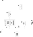
- FIG. 1 is a schematic block diagram illustrating a power supply system according to a first embodiment of the present disclosure.
- the power supply system 1 includes a power supply 11, a main load unit 12, a DC-DC voltage conversion unit 13, a bypass unit 14, and at least one sub-load unit 15.
- the power supply 11 is configured to provide an adjustable supply voltage.
- the main load unit 12 is electrically connected to the power supply 11 to receive the supply voltage, and the main load unit 12 is for example but not limited to a motor.
- the DC-DC voltage conversion unit 13 and the bypass unit 14 are electrically connected to the power supply 11 respectively and form a power module collaboratively.
- the DC-DC voltage conversion unit 13 is configured to convert the received voltage.
- the bypass unit 14 is configured to transmit the voltage without converting the received voltage.
- the sub-load unit 15 is electrically connected to the DC-DC voltage conversion unit 13 and the bypass unit 14.
- the sub-load unit 15 may include a microprocessor, a central processing unit, a universal serial bus, or a liquid crystal panel, but not limited thereto.
- the required voltage of the main load unit 12 during operation is greater than the required voltage of the sub-load unit 15 during operation.
- the supply voltage provided by the power supply 11 is equal to the required voltage of the main load unit 12.
- the main load unit 12 receives the supply voltage from the power supply 11 directly, and the supply voltage is converted by the DC-DC voltage conversion unit 13 and then provided to the sub-load unit 15.
- the power supply 11 adjusts the supply voltage to be equal to the required voltage of the sub-load unit 15, and the power supply 11 provides the adjusted supply voltage to the sub-load unit 15 through the bypass unit 14.
- the power supply 11 adjusts the supply voltage according to the required voltage of the operational load unit (i.e., the load unit which is operating). Accordingly, when the main load unit 12 with high required voltage stops operating, the voltage conversion is prevented from being performed under large voltage difference. Therefore, the work efficiency of the whole system is improved through enhancing the conversion efficiency, and meanwhile the effect of saving energy is achieved. In addition, when the main load unit 12 stops operating, the adjusted supply voltage may be provided to the sub-load unit 15 through the bypass unit 14, thereby improving the efficiency of supplying power.
- the power supply system 1 further includes a controller 16 which is in communication with the power supply 11, the main load unit 12 and the sub-load unit 15.
- the controller 16 may include a microprocessor of the sub-load unit 15 and/or a central processor of the power supply system 1, but not limited thereto.
- the controller 16 is configured for enabling the power supply 11 to adjust the supply voltage according to the required voltage of the operational load unit.
- the adjustment for the supply voltage may be realized by the controller 16 and the power supply 11 through the PD (Power Delivery) protocol or other protocol.
- the controller 16 provides the power supply 11 with a signal reflecting the required voltage of the sub-load unit 15.
- the power supply 11 adjusts the supply voltage according to the required voltage of the sub-load unit 15, and provides the adjusted supply voltage to the sub-load unit 15 through the bypass unit 14. Further, the specific manner of the controller 16 recognizing whether the main load unit 12 is operating is not limited. For example, the controller 16 may determine whether the main load unit 12 is operating according to the output current of the power supply 11 or the control command received, but not limited thereto.
- the power supply system 1a includes a plurality of sub-load units 15, and each sub-load unit 15 is electrically connected to the DC-DC voltage conversion unit 13 and the bypass unit 14 of the power module.
- each sub-load unit 15 is electrically connected to the DC-DC voltage conversion unit 13 and the bypass unit 14 of the power module.
- all the sub-load units 15 have the same required voltage during operation.
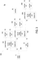
- the power supply system 1b includes N power modules 101, 102, ..., 10N and a plurality of sub-load units 15, and the plurality of sub-load units 15 forms N sub-load unit assemblies 151, 152, ..., 15N, where N is an integer larger than 1.
- Each power module (101, 102, ..., 10N) includes one DC-DC voltage conversion unit 13 and one bypass unit 14.
- the first power module 101 is electrically connected to the power supply 11.
- the first through Nth power modules 101-10N are electrically connected in series sequentially.
- Each sub-load unit assembly (151, 152, ..., 15N) includes at least one sub-load unit 15.
- the sub-load unit 15 of the first sub-load unit assembly 151 is electrically connected to the power supply 11 through the first power module 101.
- the sub-load unit 15 of the (n+1)th sub-load unit assembly 15(n+1) is electrically connected to the power supply 11 through the first to (n+1)th power modules 101-10(n+1), where n is an integer larger than or equal to 1 and smaller than N. Accordingly, the first power module 101 receives the voltage from the power supply 11 directly, and other power module receives the voltage from the correspondingly preceding power module.
- the required voltages of the sub-load units 15 of any sub-load unit assembly are the same, and the required voltage of the sub-load unit 15 of the (n+1)th sub-load unit assembly 15(n+1) is less than the required voltage of the sub-load unit 15 of the nth sub-load unit assembly 15n.
- the power supply 11 adjusts the supply voltage to be equal to the required voltage of the sub-load unit 15 of the nth sub-load unit assembly 15n.
- the power supply 11 adjusts the supply voltage to be equal to the required voltage of the sub-load unit 15 of the Nth sub-load unit assembly 15N.
- the sub-load unit 15 which stops operating e.g., enters the sleep mode
- each sub-load unit assembly includes a plurality of sub-load units 15 as shown in FIG. 3 , but not limited thereto actually.
- the sub-load unit assembly may include only one sub-load unit 15, and the number of the sub-load unit 15 included in every sub-load unit assembly may be different and unrelated.
- each power module when the voltage received by the power module is equal to the required voltage of the sub-load unit 15 connected to the power module, the voltage received by the power module is provided through the bypass unit of the power module to the sub-load unit 15 connected to the power module.
- the voltage received by the power module is not equal to the required voltage of the sub-load unit 15 connected to the power module, the voltage received by the power module is converted by the DC-DC voltage conversion unit of the power module and then provided to the sub-load unit 15 connected to the power module, where the voltage after conversion is equal to the required voltage of the sub-load unit 15 connected to the power module.
- the power module under the circumstance that the output side of a power module is connected to both the sub-load unit 15 and another power module, the power module provides the same voltage to the sub-load unit 15 and the said another power module connected therewith.
- the voltage received by the power module 101 is equal to the required voltage of the sub-load unit 15 of the sub-load unit assembly 151 connected to the power module 101. Meanwhile, the voltage received by the power module 101 is provided through the bypass unit 14 of the power module 101 to the sub-load unit 15 of the sub-load unit assembly 151 and the power module 102.
- the voltage received by the power module 101 is not equal to the required voltage of the sub-load unit 15 of the sub-load unit assembly 151, and the voltage received by the power module 101 is converted by the DC-DC voltage conversion unit 13 of the power module 101 and then provided to the sub-load unit 15 of the sub-load unit assembly 151 and the power module 102, where the voltage after conversion is equal to the required voltage of the sub-load unit 15 of the sub-load unit assembly 151.
- the voltage received by the nth power module 10n is equal to the required voltage of the sub-load unit 15 of the nth sub-load unit assembly 15n connected to the nth power module 10n.
- the voltage received by the nth power module 10n is provided through the bypass units 14 of the first to nth power module 101-10n to the sub-load unit 15 of the nth sub-load unit assembly 15n and the (n+1)th power module 10(n+1).
- the voltage received by the nth power module 10n is not equal to the required voltage of the sub-load unit 15 of the nth sub-load unit assembly 15n.
- the voltage received by the nth power module 10n is converted by the DC-DC voltage conversion unit 13 of the nth power module 10n and then provided to the sub-load unit 15 of the nth sub-load unit assembly 15n and the (n+1)th power module 10(n+1), where the voltage after conversion is equal to the required voltage of the sub-load unit 15 of the nth sub-load unit assembly 15n.
- the controller 16 when the main load unit 12 stops operating and the sub-load unit 15 of the sub-load unit assembly 151 connected to the power module 101 operates normally at an operating voltage, the controller 16 provides the power supply 11 with a signal reflecting the required voltage of the sub-load unit 15 of the sub-load unit assembly 151, and the power supply 11 adjusts the supply voltage to be equal to the required voltage of the sub-load unit 15 of the sub-load unit assembly 151. Further, the supply voltage provided by the power supply 11 is provided through the bypass unit 14 of the power module 101 to the sub-load unit assembly 151 and the power module 102. Under this circumstance, the voltages received by the power modules 101 and 102 are both equal to the required voltage of the sub-load unit 15 of the sub-load unit assembly 151.
- the controller 16 provides the power supply 11 with a signal reflecting the required voltage of the sub-load unit 15 of the sub-load unit assembly 15n, and the power supply 11 adjusts the supply voltage to be equal to the required voltage of the sub-load unit 15 of the sub-load unit assembly 15n. Further, the supply voltage provided by the power supply 11 is provided through the bypass units 14 of the power modules 101-10n to the sub-load unit assembly 15n and the power module 10(n+1). Under this circumstance, the voltages received by the power modules 101-10(n+1) are all equal to the required voltage of the sub-load unit 15 of the sub-load unit assembly 15n.
- all of the main load unit 12, the DC-DC voltage conversion unit(s) 13, the bypass unit(s) 14, the sub-load unit(s) 15 and the controller 16 may form a power receiving system 100 collaboratively.
- the power receiving system 100 may be electrically connected to the power supply 11 through a single port 200 so as to receive the supply voltage and reflect the required voltage.
- the port 200 is for example but not limited to a USB (universal serial bus) Type-C port.
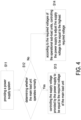
- FIG. 4 is a schematic flow chart illustrating a control method of a power supply system according to an embodiment of the present disclosure.
- the control method is applicable for the power supply system (1, 1a, 1b) in any of the above-mentioned embodiments.
- a power supply system (1, 1a, 1b) is provided.
- the power supply system (1, 1a, 1b) includes a power supply 11, a main load unit 12, a DC-DC voltage conversion unit 13, a bypass unit 14, and sub-load unit(s) 15.
- step S12 whether the main load unit 12 operates normally is determined.
- the step S13 is performed to control the supply voltage provided by the power supply 11 to be equal to the required voltage of the main load unit 12. If the determination result is negative (i.e., the main load unit 12 stops operating), the step S14 is performed. In the step S14, according to the required voltages of the operational sub-load units 15, the power supply 11 is controlled to adjust the supply voltage to be equal to the highest required voltage among the operational sub-load units 15.
- the present disclosure provides a power supply system including a power supply that adjusts a supply voltage thereof according to the required voltage of the operational load unit. Accordingly, when the main load unit with high required voltage stops operating, the voltage conversion is prevented from being performed under large voltage difference. Therefore, the work efficiency of the whole system is improved through enhancing the conversion efficiency, and meanwhile the effect of saving energy is achieved. In addition, when the main load unit stops operating, the adjusted supply voltage may be provided to the sub-load unit through the bypass unit, thereby improving the efficiency of supplying power.
Landscapes
- Engineering & Computer Science (AREA)
- Power Engineering (AREA)
- Direct Current Feeding And Distribution (AREA)
Abstract
Description
- The present disclosure relates to a power supply system, and more particularly to a power supply system capable of improving the work efficiency.
- Conventionally, the voltage outputted by the power supply is constant and equals the highest required voltage in the system. Then, the DC-DC voltage converter in the system converts the voltage from the power supply and provides the converted voltage to the part with lower required voltage of the system. Under this architecture, when the part with high required voltage of the system stops operating (e.g., enters the sleep mode), the power supply still supplies the power with high required voltage. Therefore, the voltage difference between two ends of the DC-DC voltage converter in the system is still maintained at a high value, resulting in bad conversion efficiency.
- Therefore, there is a need of providing a power supply system in order to overcome the drawbacks of the conventional technologies.
- The present disclosure provides a power supply system including a power supply that adjusts a supply voltage thereof according to the required voltage of the operational load unit. Accordingly, when the main load unit with high required voltage stops operating, the voltage conversion is prevented from being performed under large voltage difference. Therefore, the work efficiency of the whole system is improved through enhancing the conversion efficiency, and meanwhile the effect of saving energy is achieved. In addition, when the main load unit stops operating, the adjusted supply voltage may be provided to the sub-load unit through the bypass unit, thereby improving the efficiency of supplying power.
- In accordance with an aspect of the present disclosure, a power supply system is provided. The power supply system includes a power supply, a main load unit, a DC-DC voltage conversion unit, a bypass unit, and at least one sub-load unit. The power supply is configured to provide an adjustable supply voltage. The main load unit is electrically connected to the power supply for receiving the supply voltage. The DC-DC voltage conversion unit is electrically connected to the power supply. The bypass unit is electrically connected to the power supply. The at least one sub-load unit is electrically connected to the DC-DC voltage conversion unit and the bypass unit. When the main load unit stops operating, the power supply adjusts the supply voltage and provides the adjusted supply voltage to the sub-load unit through the bypass unit.
- In accordance with another aspect of the present disclosure, a power supply system is provided. The power supply system includes a power supply and a power receiving system. The power supply is configured to provide an adjustable supply voltage. The power receiving system is electrically connected to the power supply through a port for receiving the supply voltage and includes a main load unit, a DC-DC voltage conversion unit, a bypass unit, and at least one sub-load unit. The main load unit is electrically connected to the power supply for receiving the supply voltage. The DC-DC voltage conversion unit is electrically connected to the power supply. The bypass unit is electrically connected to the power supply. The at least one sub-load unit is electrically connected to the DC-DC voltage conversion unit and the bypass unit. When the main load unit stops operating, the power supply adjusts the supply voltage and provides the adjusted supply voltage to the sub-load unit through the bypass unit.
-
-
FIG. 1 is a schematic block diagram illustrating a power supply system according to a first embodiment of the present disclosure; -
FIG. 2 is a schematic block diagram illustrating a power supply system according to a second embodiment of the present disclosure; -
FIG. 3 is a schematic block diagram illustrating a power supply system according to a third embodiment of the present disclosure; and -
FIG. 4 is schematic flow chart illustrating a control method of a power supply system according to an embodiment of the present disclosure. - The present disclosure will now be described more specifically with reference to the following embodiments. It is to be noted that the following descriptions of preferred embodiments of this disclosure are presented herein for purpose of illustration and description only. It is not intended to be exhaustive or to be limited to the precise form disclosed.
-
FIG. 1 is a schematic block diagram illustrating a power supply system according to a first embodiment of the present disclosure. As shown inFIG. 1 , thepower supply system 1 includes apower supply 11, amain load unit 12, a DC-DCvoltage conversion unit 13, abypass unit 14, and at least onesub-load unit 15. Thepower supply 11 is configured to provide an adjustable supply voltage. Themain load unit 12 is electrically connected to thepower supply 11 to receive the supply voltage, and themain load unit 12 is for example but not limited to a motor. The DC-DCvoltage conversion unit 13 and thebypass unit 14 are electrically connected to thepower supply 11 respectively and form a power module collaboratively. The DC-DCvoltage conversion unit 13 is configured to convert the received voltage. Thebypass unit 14 is configured to transmit the voltage without converting the received voltage. Thesub-load unit 15 is electrically connected to the DC-DCvoltage conversion unit 13 and thebypass unit 14. For example, thesub-load unit 15 may include a microprocessor, a central processing unit, a universal serial bus, or a liquid crystal panel, but not limited thereto. In an embodiment, the required voltage of themain load unit 12 during operation is greater than the required voltage of thesub-load unit 15 during operation. - When the
main load unit 12 operates normally at an operating voltage, the supply voltage provided by thepower supply 11 is equal to the required voltage of themain load unit 12. Themain load unit 12 receives the supply voltage from thepower supply 11 directly, and the supply voltage is converted by the DC-DCvoltage conversion unit 13 and then provided to thesub-load unit 15. - When the
main load unit 12 stops operating (e.g., enters the sleep mode), thepower supply 11 adjusts the supply voltage to be equal to the required voltage of thesub-load unit 15, and thepower supply 11 provides the adjusted supply voltage to thesub-load unit 15 through thebypass unit 14. - Consequently, the
power supply 11 adjusts the supply voltage according to the required voltage of the operational load unit (i.e., the load unit which is operating). Accordingly, when themain load unit 12 with high required voltage stops operating, the voltage conversion is prevented from being performed under large voltage difference. Therefore, the work efficiency of the whole system is improved through enhancing the conversion efficiency, and meanwhile the effect of saving energy is achieved. In addition, when themain load unit 12 stops operating, the adjusted supply voltage may be provided to thesub-load unit 15 through thebypass unit 14, thereby improving the efficiency of supplying power. - In an embodiment, the
power supply system 1 further includes acontroller 16 which is in communication with thepower supply 11, themain load unit 12 and thesub-load unit 15. Thecontroller 16 may include a microprocessor of thesub-load unit 15 and/or a central processor of thepower supply system 1, but not limited thereto. Thecontroller 16 is configured for enabling thepower supply 11 to adjust the supply voltage according to the required voltage of the operational load unit. The adjustment for the supply voltage may be realized by thecontroller 16 and thepower supply 11 through the PD (Power Delivery) protocol or other protocol. For example, in the embodiment shown inFIG. 1 , when themain load unit 12 stops operating, thecontroller 16 provides thepower supply 11 with a signal reflecting the required voltage of thesub-load unit 15. Thepower supply 11 adjusts the supply voltage according to the required voltage of thesub-load unit 15, and provides the adjusted supply voltage to thesub-load unit 15 through thebypass unit 14. Further, the specific manner of thecontroller 16 recognizing whether themain load unit 12 is operating is not limited. For example, thecontroller 16 may determine whether themain load unit 12 is operating according to the output current of thepower supply 11 or the control command received, but not limited thereto. - In the embodiment shown in
FIG. 1 , only onesub-load unit 15 is exemplified, but the number of thesub-load units 15 is not limited actually. For example, in the embodiment shown inFIG. 2 , thepower supply system 1a includes a plurality ofsub-load units 15, and eachsub-load unit 15 is electrically connected to the DC-DCvoltage conversion unit 13 and thebypass unit 14 of the power module. Preferably, all thesub-load units 15 have the same required voltage during operation. - Please refer to
FIG. 3 . In an embodiment, thepower supply system 1b includesN power modules sub-load units 15, and the plurality ofsub-load units 15 forms Nsub-load unit assemblies voltage conversion unit 13 and onebypass unit 14. Thefirst power module 101 is electrically connected to thepower supply 11. The first through Nth power modules 101-10N are electrically connected in series sequentially. Each sub-load unit assembly (151, 152, ..., 15N) includes at least onesub-load unit 15. Thesub-load unit 15 of the firstsub-load unit assembly 151 is electrically connected to thepower supply 11 through thefirst power module 101. Thesub-load unit 15 of the (n+1)th sub-load unit assembly 15(n+1) is electrically connected to thepower supply 11 through the first to (n+1)th power modules 101-10(n+1), where n is an integer larger than or equal to 1 and smaller than N. Accordingly, thefirst power module 101 receives the voltage from thepower supply 11 directly, and other power module receives the voltage from the correspondingly preceding power module. In an embodiment, during operation, the required voltages of thesub-load units 15 of any sub-load unit assembly are the same, and the required voltage of thesub-load unit 15 of the (n+1)th sub-load unit assembly 15(n+1) is less than the required voltage of thesub-load unit 15 of the nth sub-load unit assembly 15n. - When the
main load unit 12 and a part of thesub-load units 15 stop operating (e.g., enters the sleep mode), thecontroller 16 provides thepower supply 11 with a signal reflecting the required voltages of the other operationalsub-load units 15, and thepower supply 11 adjusts the supply voltage to be equal to the highest required voltage among the operationalsub-load units 15. For example, when n=1 and themain load unit 12 stops operating, thepower supply 11 adjusts the supply voltage to be equal to the required voltage of thesub-load unit 15 of the firstsub-load unit assembly 151. When n>1 and themain load unit 12 and thesub-load units 15 of the first to (n-1)th sub-load unit assemblies 151-15(n-1) stop operating, thepower supply 11 adjusts the supply voltage to be equal to the required voltage of thesub-load unit 15 of the nth sub-load unit assembly 15n. When themain load unit 12 and thesub-load units 15 of the first to (N-1)th sub-load unit assemblies 151-15(N-1) stop operating, thepower supply 11 adjusts the supply voltage to be equal to the required voltage of thesub-load unit 15 of the Nthsub-load unit assembly 15N. In an embodiment, thesub-load unit 15 which stops operating (e.g., enters the sleep mode) may receive a voltage less than or equal to its operating voltage. - In addition, it is noted that each sub-load unit assembly includes a plurality of
sub-load units 15 as shown inFIG. 3 , but not limited thereto actually. The sub-load unit assembly may include only onesub-load unit 15, and the number of thesub-load unit 15 included in every sub-load unit assembly may be different and unrelated. - In each power module, when the voltage received by the power module is equal to the required voltage of the
sub-load unit 15 connected to the power module, the voltage received by the power module is provided through the bypass unit of the power module to thesub-load unit 15 connected to the power module. On the contrary, when the voltage received by the power module is not equal to the required voltage of thesub-load unit 15 connected to the power module, the voltage received by the power module is converted by the DC-DC voltage conversion unit of the power module and then provided to thesub-load unit 15 connected to the power module, where the voltage after conversion is equal to the required voltage of thesub-load unit 15 connected to the power module. In addition, under the circumstance that the output side of a power module is connected to both thesub-load unit 15 and another power module, the power module provides the same voltage to thesub-load unit 15 and the said another power module connected therewith. - Taking the
power module 101 as an example, under the circumstance that thesub-load unit 15 of thesub-load unit assembly 151 connected to thepower module 101 operates normally at an operating voltage, when themain load unit 12 stops operating, the voltage received by thepower module 101 is equal to the required voltage of thesub-load unit 15 of thesub-load unit assembly 151 connected to thepower module 101. Meanwhile, the voltage received by thepower module 101 is provided through thebypass unit 14 of thepower module 101 to thesub-load unit 15 of thesub-load unit assembly 151 and thepower module 102. On the contrary, when themain load unit 12 operates normally at the operating voltage, the voltage received by thepower module 101 is not equal to the required voltage of thesub-load unit 15 of thesub-load unit assembly 151, and the voltage received by thepower module 101 is converted by the DC-DCvoltage conversion unit 13 of thepower module 101 and then provided to thesub-load unit 15 of thesub-load unit assembly 151 and thepower module 102, where the voltage after conversion is equal to the required voltage of thesub-load unit 15 of thesub-load unit assembly 151. - Likewise, taking the nth power module 10n as an example, under the circumstance that the
sub-load unit 15 of the nth sub-load unit assembly 15n connected to the nth power module 10n operates normally at an operating voltage, when n=1 and themain load unit 12 stops operating, or when n>1 and themain load unit 12 and thesub-load units 15 of the first to (n-1)th sub-load unit assemblies 151-15(n-1) stop operating, the voltage received by the nth power module 10n is equal to the required voltage of thesub-load unit 15 of the nth sub-load unit assembly 15n connected to the nth power module 10n. Meanwhile, the voltage received by the nth power module 10n is provided through thebypass units 14 of the first to nth power module 101-10n to thesub-load unit 15 of the nth sub-load unit assembly 15n and the (n+1)th power module 10(n+1). On the contrary, when n=1 and themain load unit 12 operates normally at the operating voltage, or when n>1 and themain load unit 12 or any of thesub-load units 15 of the first to (n-1)th sub-load unit assemblies 151-15(n-1) operates normally at the operating voltage, the voltage received by the nth power module 10n is not equal to the required voltage of thesub-load unit 15 of the nth sub-load unit assembly 15n. Meanwhile, the voltage received by the nth power module 10n is converted by the DC-DCvoltage conversion unit 13 of the nth power module 10n and then provided to thesub-load unit 15 of the nth sub-load unit assembly 15n and the (n+1)th power module 10(n+1), where the voltage after conversion is equal to the required voltage of thesub-load unit 15 of the nth sub-load unit assembly 15n. - In an embodiment, when the
main load unit 12 stops operating and thesub-load unit 15 of thesub-load unit assembly 151 connected to thepower module 101 operates normally at an operating voltage, thecontroller 16 provides thepower supply 11 with a signal reflecting the required voltage of thesub-load unit 15 of thesub-load unit assembly 151, and thepower supply 11 adjusts the supply voltage to be equal to the required voltage of thesub-load unit 15 of thesub-load unit assembly 151. Further, the supply voltage provided by thepower supply 11 is provided through thebypass unit 14 of thepower module 101 to thesub-load unit assembly 151 and thepower module 102. Under this circumstance, the voltages received by thepower modules sub-load unit 15 of thesub-load unit assembly 151. In the case that n>1, when themain load unit 12 and thesub-load units 15 of the sub-load unit assemblies 151-15(n-1) stop operating and thesub-load unit 15 of the sub-load unit assembly 15n connected to the power module 10n operates normally at an operating voltage, thecontroller 16 provides thepower supply 11 with a signal reflecting the required voltage of thesub-load unit 15 of the sub-load unit assembly 15n, and thepower supply 11 adjusts the supply voltage to be equal to the required voltage of thesub-load unit 15 of the sub-load unit assembly 15n. Further, the supply voltage provided by thepower supply 11 is provided through thebypass units 14 of the power modules 101-10n to the sub-load unit assembly 15n and the power module 10(n+1). Under this circumstance, the voltages received by the power modules 101-10(n+1) are all equal to the required voltage of thesub-load unit 15 of the sub-load unit assembly 15n. - In each embodiment of the present disclosure as shown in
FIGS. 1 ,2 and3 , all of themain load unit 12, the DC-DC voltage conversion unit(s) 13, the bypass unit(s) 14, the sub-load unit(s) 15 and thecontroller 16 may form apower receiving system 100 collaboratively. Thepower receiving system 100 may be electrically connected to thepower supply 11 through asingle port 200 so as to receive the supply voltage and reflect the required voltage. Theport 200 is for example but not limited to a USB (universal serial bus) Type-C port. -
FIG. 4 is a schematic flow chart illustrating a control method of a power supply system according to an embodiment of the present disclosure. The control method is applicable for the power supply system (1, 1a, 1b) in any of the above-mentioned embodiments. As shown inFIG. 4 , firstly, in step S11, a power supply system (1, 1a, 1b) is provided. The power supply system (1, 1a, 1b) includes apower supply 11, amain load unit 12, a DC-DCvoltage conversion unit 13, abypass unit 14, and sub-load unit(s) 15. Then, in the step S12, whether themain load unit 12 operates normally is determined. If the determination result is positive (i.e., themain load unit 12 operates normally at an operating voltage), the step S13 is performed to control the supply voltage provided by thepower supply 11 to be equal to the required voltage of themain load unit 12. If the determination result is negative (i.e., themain load unit 12 stops operating), the step S14 is performed. In the step S14, according to the required voltages of the operationalsub-load units 15, thepower supply 11 is controlled to adjust the supply voltage to be equal to the highest required voltage among the operationalsub-load units 15. - In summary, the present disclosure provides a power supply system including a power supply that adjusts a supply voltage thereof according to the required voltage of the operational load unit. Accordingly, when the main load unit with high required voltage stops operating, the voltage conversion is prevented from being performed under large voltage difference. Therefore, the work efficiency of the whole system is improved through enhancing the conversion efficiency, and meanwhile the effect of saving energy is achieved. In addition, when the main load unit stops operating, the adjusted supply voltage may be provided to the sub-load unit through the bypass unit, thereby improving the efficiency of supplying power.
Claims (18)
- A power supply system (1), characterized by comprising:a power supply (11), configured to provide an adjustable supply voltage;a main load unit (12), electrically connected to the power supply (11) for receiving the supply voltage;a DC-DC voltage conversion unit (13), electrically connected to the power supply (11);a bypass unit (14), electrically connected to the power supply (11); andat least one sub-load unit (15), electrically connected to the DC-DC voltage conversion unit (13) and the bypass unit (14),wherein when the main load unit (12) stops operating, the power supply (11) adjusts the supply voltage and provides the adjusted supply voltage to the sub-load unit (15) through the bypass unit (14).
- The power supply system (1) according to claim 1, further comprising a controller (16), wherein when the main load unit (12) stops operating, the controller (16) provides the power supply (11) with a signal reflecting a required voltage of the sub-load unit (15), the power supply (11) adjusts the supply voltage according to the required voltage.
- The power supply system (1b) according to claim 1, comprising N power modules (101-10N) and a plurality of said sub-load units (15), wherein N is an integer larger than 1, each of the N power modules (101-10N) comprises one said DC-DC voltage conversion unit (13) and one said bypass unit (14), the first power module (101) is electrically connected to the power supply (11), the first through Nth power modules (101-10N) are electrically connected in series sequentially, the plurality of sub-load units (15) forms N sub-load unit assemblies (151-15N) each comprising at least one sub-load unit (15), the at least one sub-load unit (15) of the first sub-load unit assembly (151) is electrically connected to the power supply (11) through the first power module (101), and the at least one sub-load unit (15) of the (n+1)th sub-load unit assembly (15N) is electrically connected to the power supply (11) through the first to (n+1)th power modules (101-10N), where n is an integer larger than or equal to 1 and smaller than N.
- The power supply system (1b) according to claim 3, wherein in each of the N power modules (101-10N), when a voltage received by the power module (101) is equal to a required voltage of the sub-load unit (15) connected to the power module (101), the voltage received by the power module (101) is provided through the bypass unit (14) of the power module (101) to the sub-load unit (15) connected to the power module (101).
- The power supply system (1b) according to claim 3, wherein in each of the N power modules (101-10N), when a voltage received by the power module (101) is not equal to a required voltage of the sub-load unit (15) connected to the power module (101), the voltage received by the power module (101) is converted by the DC-DC voltage conversion unit (13) of the power module (101) and then provided to the sub-load unit (15) connected to the power module (101).
- The power supply system (1b) according to claim 3, wherein when a voltage received by the nth power module (101) is equal to a required voltage of the sub-load unit (15) of the nth sub-load unit assembly (151) connected to the nth power module (101), the voltage received by the nth power module (101) is provided through the bypass unit (14) of the nth power module (101) to the sub-load unit (15) of the nth sub-load unit assembly (151) and the (n+1)th power module (102).
- The power supply system (1b) according to claim 3, wherein when a voltage received by the nth power module (101) is not equal to a required voltage of the sub-load unit (15) of the nth sub-load unit assembly (151) connected to the nth power module (101), the voltage received by the nth power module (101) is converted by the DC-DC voltage conversion unit (13) of the nth power module (101) and then provided to the sub-load unit (15) of the nth sub-load unit assembly (151) and the (n+1)th power module (102).
- The power supply system (1b) according to claim 3, further comprising a controller (16), wherein when the main load unit (12) stops operating, the controller (16) provides the power supply (11) with a signal reflecting required voltages of the plurality of sub-load units (15), the power supply (11) adjusts the supply voltage according to the required voltages of the plurality of sub-load units (15).
- The power supply system (1b) according to claim 3, further comprising a controller (16), wherein when the main load unit (12) and a part of the sub-load units (15) stop operating, the controller (16) provides the power supply (11) with a signal reflecting required voltages of the other operational sub-load units (15), the power supply (11) adjusts the supply voltage to be equal to a highest one of the required voltages of the other operational sub-load units (15).
- A power supply system (1), characterized by comprising:a power supply (11), configured to provide an adjustable supply voltage; anda power receiving system (100), electrically connected to the power supply (11) through a port (200) for receiving the supply voltage, and comprising:a main load unit (12), electrically connected to the power supply (11) for receiving the supply voltage;a DC-DC voltage conversion unit (13), electrically connected to the power supply (11);a bypass unit (14), electrically connected to the power supply (11); andat least one sub-load unit (15), electrically connected to the DC-DC voltage conversion unit (13) and the bypass unit (14),wherein when the main load unit (12) stops operating, the power supply (11) adjusts the supply voltage and provides the adjusted supply voltage to the sub-load unit (15) through the bypass unit (14).
- The power supply system (1) according to claim 10, further comprising a controller (16), wherein when the main load unit (12) stops operating, the controller (16) provides the power supply (11) with a signal reflecting a required voltage of the sub-load unit (15), the power supply (11) adjusts the supply voltage according to the required voltage, and the power supply (11) provides the adjusted supply voltage to the sub-load unit (15) through the bypass unit (14).
- The power supply system (1b) according to claim 10, wherein the power receiving system (100) comprises N power modules (101-10N) and a plurality of said sub-load units (15), N is an integer larger than 1, each of the N power modules (101-10N) comprises one said DC-DC voltage conversion unit (13) and one said bypass unit (14), the first power module (101) is electrically connected to the power supply (11), the first through Nth power modules (101-10N) are electrically connected in series sequentially, the plurality of sub-load units (15) forms N sub-load unit assemblies (151-15N) each comprising at least one sub-load unit (15), the at least one sub-load unit (15) of the first sub-load unit assembly (151) is electrically connected to the power supply (11) through the first power module (101), and the at least one sub-load unit (15) of the (n+1)th sub-load unit assembly (15N) is electrically connected to the power supply (11) through the first to (n+1)th power modules (101-10N), where n is an integer larger than or equal to 1 and smaller than N.
- The power supply system (1b) according to claim 12, wherein in each of the N power modules (101-10N), when a voltage received by the power module (101) is equal to a required voltage of the sub-load unit (15) connected to the power module (101), the voltage received by the power module (101) is provided through the bypass unit (14) of the power module (101) to the sub-load unit (15) connected to the power module (101).
- The power supply system (1b) according to claim 12, wherein in each of the N power modules (101-10N), when a voltage received by the power module (101) is not equal to a required voltage of the sub-load unit (15) connected to the power module (101), the voltage received by the power module (101) is converted by the DC-DC voltage conversion unit (13) of the power module (101) and then provided to the sub-load unit (15) connected to the power module (101).
- The power supply system (1b) according to claim 12, wherein when a voltage received by the nth power module (101) is equal to a required voltage of the sub-load unit (15) of the nth sub-load unit assembly (151) connected to the nth power module (101), the voltage received by the nth power module (101) is provided through the bypass unit (14) of the nth power module (101) to the sub-load unit (15) of the nth sub-load unit assembly (151) and the (n+1)th power module (102).
- The power supply system (1b) according to claim 12, wherein when a voltage received by the nth power module (101) is not equal to a required voltage of the sub-load unit (15) of the nth sub-load unit assembly (151) connected to the nth power module (101), the voltage received by the nth power module (101) is converted by the DC-DC voltage conversion unit (13) of the nth power module (101) and then provided to the sub-load unit (15) of the nth sub-load unit assembly (151) and the (n+1)th power module (102).
- The power supply system (1b) according to claim 12, further comprising a controller (16), wherein when the main load unit (12) stops operating, the controller (16) provides the power supply (11) with a signal reflecting required voltages of the plurality of sub-load units (15), the power supply adjusts the supply voltage according to the required voltages of the plurality of sub-load units (15).
- The power supply system (1b) according to claim 12, further comprising a controller (16), wherein when the main load unit (12) and a part of the sub-load units (15) stop operating, the controller (16) provides the power supply (11) with a signal reflecting required voltages of the other operational sub-load units (15), the power supply (11) adjusts the supply voltage to be equal to a highest one of the required voltages of the other operational sub-load units (15).
Applications Claiming Priority (2)
| Application Number | Priority Date | Filing Date | Title |
|---|---|---|---|
| CN202210920669 | 2022-08-02 | ||
| CN202310484478.5A CN117498292A (en) | 2022-08-02 | 2023-04-28 | Power supply system |
Publications (2)
| Publication Number | Publication Date |
|---|---|
| EP4318841A2 true EP4318841A2 (en) | 2024-02-07 |
| EP4318841A3 EP4318841A3 (en) | 2024-03-20 |
Family
ID=86942233
Family Applications (1)
| Application Number | Title | Priority Date | Filing Date |
|---|---|---|---|
| EP23180967.4A Pending EP4318841A3 (en) | 2022-08-02 | 2023-06-22 | Power supply system |
Country Status (2)
| Country | Link |
|---|---|
| US (1) | US20240048040A1 (en) |
| EP (1) | EP4318841A3 (en) |
Families Citing this family (1)
| Publication number | Priority date | Publication date | Assignee | Title |
|---|---|---|---|---|
| TWI835187B (en) * | 2022-07-04 | 2024-03-11 | 立錡科技股份有限公司 | High efficiency power supply system having multiple ports |
Family Cites Families (2)
| Publication number | Priority date | Publication date | Assignee | Title |
|---|---|---|---|---|
| WO2011026047A1 (en) * | 2009-08-28 | 2011-03-03 | Green Plug | High-and low-power power supply with standby power saving features |
| JP7074725B2 (en) * | 2019-07-18 | 2022-05-24 | 矢崎総業株式会社 | Power supply system, DCDC converter device, and charging method |
-
2023
- 2023-06-22 EP EP23180967.4A patent/EP4318841A3/en active Pending
- 2023-06-22 US US18/213,077 patent/US20240048040A1/en active Pending
Also Published As
| Publication number | Publication date |
|---|---|
| US20240048040A1 (en) | 2024-02-08 |
| EP4318841A3 (en) | 2024-03-20 |
Similar Documents
| Publication | Publication Date | Title |
|---|---|---|
| US10998814B2 (en) | Power conversion system, controller for the same, and method for controlling the same | |
| US8890535B2 (en) | Power supply aging system and load balance control method | |
| US11886217B2 (en) | Control device and solar power generation system | |
| JP2002171692A (en) | DC power supply | |
| US9688158B2 (en) | Power driving system | |
| US12237683B2 (en) | Photovoltaic rapid shutdown system and control method therefor | |
| US20240048040A1 (en) | Power supply system | |
| US11749993B2 (en) | Method to overcome electrical circuit voltage and current limitations | |
| US20210328240A1 (en) | Fuel cell energy supply system and energy regulation method based on same | |
| EP3855595B1 (en) | Photovoltaic system | |
| US12074522B2 (en) | Power conversion device with parallel DC-DC coverters and multiple driving modes | |
| US10020751B1 (en) | Multi-output control system and operating method for the same | |
| CN112366751B (en) | A photovoltaic system with mixed components with different characteristics | |
| EP4398436A1 (en) | Energy storage system and control method thereof | |
| JP2001309560A (en) | Grid-connected inverter device | |
| CN117498292A (en) | Power supply system | |
| TWI873611B (en) | Power supply system | |
| US10530271B2 (en) | Power conversion device and power conversion system | |
| EP3972101A1 (en) | Modular conversion system with individual bridge outputs and stacked dc-link balancing by means of zero-vector switching | |
| JP5064762B2 (en) | Discharge lamp drive unit | |
| CN117955426B (en) | Power equipment, power equipment control method and photovoltaic power generation system | |
| JP7142673B2 (en) | Power supply device and its power supply method | |
| EP4654467A1 (en) | Method and device for performing safety function | |
| CN113014083A (en) | Adapter and port voltage adjusting method thereof | |
| CN220584649U (en) | System for optimizing working performance of chip |
Legal Events
| Date | Code | Title | Description |
|---|---|---|---|
| PUAI | Public reference made under article 153(3) epc to a published international application that has entered the european phase |
Free format text: ORIGINAL CODE: 0009012 |
|
| STAA | Information on the status of an ep patent application or granted ep patent |
Free format text: STATUS: THE APPLICATION HAS BEEN PUBLISHED |
|
| AK | Designated contracting states |
Kind code of ref document: A2 Designated state(s): AL AT BE BG CH CY CZ DE DK EE ES FI FR GB GR HR HU IE IS IT LI LT LU LV MC ME MK MT NL NO PL PT RO RS SE SI SK SM TR |
|
| PUAL | Search report despatched |
Free format text: ORIGINAL CODE: 0009013 |
|
| AK | Designated contracting states |
Kind code of ref document: A3 Designated state(s): AL AT BE BG CH CY CZ DE DK EE ES FI FR GB GR HR HU IE IS IT LI LT LU LV MC ME MK MT NL NO PL PT RO RS SE SI SK SM TR |
|
| RIC1 | Information provided on ipc code assigned before grant |
Ipc: H02M 3/158 20060101ALI20240213BHEP Ipc: H02M 1/00 20060101ALI20240213BHEP Ipc: H02J 1/10 20060101ALI20240213BHEP Ipc: H02J 1/00 20060101AFI20240213BHEP |
|
| STAA | Information on the status of an ep patent application or granted ep patent |
Free format text: STATUS: REQUEST FOR EXAMINATION WAS MADE |
|
| 17P | Request for examination filed |
Effective date: 20240823 |
|
| RBV | Designated contracting states (corrected) |
Designated state(s): AL AT BE BG CH CY CZ DE DK EE ES FI FR GB GR HR HU IE IS IT LI LT LU LV MC ME MK MT NL NO PL PT RO RS SE SI SK SM TR |