EP4318824A1 - Joint connector, connector-equipped electric wire, and connector case - Google Patents
Joint connector, connector-equipped electric wire, and connector case Download PDFInfo
- Publication number
- EP4318824A1 EP4318824A1 EP22774979.3A EP22774979A EP4318824A1 EP 4318824 A1 EP4318824 A1 EP 4318824A1 EP 22774979 A EP22774979 A EP 22774979A EP 4318824 A1 EP4318824 A1 EP 4318824A1
- Authority
- EP
- European Patent Office
- Prior art keywords
- side plate
- connector
- plate part
- engaging
- cases
- Prior art date
- Legal status (The legal status is an assumption and is not a legal conclusion. Google has not performed a legal analysis and makes no representation as to the accuracy of the status listed.)
- Pending
Links
- 210000000078 claw Anatomy 0.000 claims abstract description 71
- 239000004020 conductor Substances 0.000 description 3
- 230000000694 effects Effects 0.000 description 3
- 238000002788 crimping Methods 0.000 description 2
- 239000012212 insulator Substances 0.000 description 2
- 230000001629 suppression Effects 0.000 description 1
- 229920003002 synthetic resin Polymers 0.000 description 1
- 239000000057 synthetic resin Substances 0.000 description 1
Images




Classifications
-
- H—ELECTRICITY
- H01—ELECTRIC ELEMENTS
- H01R—ELECTRICALLY-CONDUCTIVE CONNECTIONS; STRUCTURAL ASSOCIATIONS OF A PLURALITY OF MUTUALLY-INSULATED ELECTRICAL CONNECTING ELEMENTS; COUPLING DEVICES; CURRENT COLLECTORS
- H01R13/00—Details of coupling devices of the kinds covered by groups H01R12/70 or H01R24/00 - H01R33/00
- H01R13/46—Bases; Cases
- H01R13/514—Bases; Cases composed as a modular blocks or assembly, i.e. composed of co-operating parts provided with contact members or holding contact members between them
-
- H—ELECTRICITY
- H01—ELECTRIC ELEMENTS
- H01R—ELECTRICALLY-CONDUCTIVE CONNECTIONS; STRUCTURAL ASSOCIATIONS OF A PLURALITY OF MUTUALLY-INSULATED ELECTRICAL CONNECTING ELEMENTS; COUPLING DEVICES; CURRENT COLLECTORS
- H01R13/00—Details of coupling devices of the kinds covered by groups H01R12/70 or H01R24/00 - H01R33/00
- H01R13/46—Bases; Cases
- H01R13/502—Bases; Cases composed of different pieces
- H01R13/508—Bases; Cases composed of different pieces assembled by a separate clip or spring
-
- H—ELECTRICITY
- H01—ELECTRIC ELEMENTS
- H01R—ELECTRICALLY-CONDUCTIVE CONNECTIONS; STRUCTURAL ASSOCIATIONS OF A PLURALITY OF MUTUALLY-INSULATED ELECTRICAL CONNECTING ELEMENTS; COUPLING DEVICES; CURRENT COLLECTORS
- H01R31/00—Coupling parts supported only by co-operation with counterpart
- H01R31/08—Short-circuiting members for bridging contacts in a counterpart
-
- H—ELECTRICITY
- H01—ELECTRIC ELEMENTS
- H01R—ELECTRICALLY-CONDUCTIVE CONNECTIONS; STRUCTURAL ASSOCIATIONS OF A PLURALITY OF MUTUALLY-INSULATED ELECTRICAL CONNECTING ELEMENTS; COUPLING DEVICES; CURRENT COLLECTORS
- H01R11/00—Individual connecting elements providing two or more spaced connecting locations for conductive members which are, or may be, thereby interconnected, e.g. end pieces for wires or cables supported by the wire or cable and having means for facilitating electrical connection to some other wire, terminal, or conductive member, blocks of binding posts
- H01R11/03—Individual connecting elements providing two or more spaced connecting locations for conductive members which are, or may be, thereby interconnected, e.g. end pieces for wires or cables supported by the wire or cable and having means for facilitating electrical connection to some other wire, terminal, or conductive member, blocks of binding posts characterised by the relationship between the connecting locations
- H01R11/05—Individual connecting elements providing two or more spaced connecting locations for conductive members which are, or may be, thereby interconnected, e.g. end pieces for wires or cables supported by the wire or cable and having means for facilitating electrical connection to some other wire, terminal, or conductive member, blocks of binding posts characterised by the relationship between the connecting locations the connecting locations having different types of direct connections
-
- H—ELECTRICITY
- H01—ELECTRIC ELEMENTS
- H01R—ELECTRICALLY-CONDUCTIVE CONNECTIONS; STRUCTURAL ASSOCIATIONS OF A PLURALITY OF MUTUALLY-INSULATED ELECTRICAL CONNECTING ELEMENTS; COUPLING DEVICES; CURRENT COLLECTORS
- H01R12/00—Structural associations of a plurality of mutually-insulated electrical connecting elements, specially adapted for printed circuits, e.g. printed circuit boards [PCB], flat or ribbon cables, or like generally planar structures, e.g. terminal strips, terminal blocks; Coupling devices specially adapted for printed circuits, flat or ribbon cables, or like generally planar structures; Terminals specially adapted for contact with, or insertion into, printed circuits, flat or ribbon cables, or like generally planar structures
- H01R12/50—Fixed connections
- H01R12/59—Fixed connections for flexible printed circuits, flat or ribbon cables or like structures
- H01R12/63—Fixed connections for flexible printed circuits, flat or ribbon cables or like structures connecting to another shape cable
-
- H—ELECTRICITY
- H01—ELECTRIC ELEMENTS
- H01R—ELECTRICALLY-CONDUCTIVE CONNECTIONS; STRUCTURAL ASSOCIATIONS OF A PLURALITY OF MUTUALLY-INSULATED ELECTRICAL CONNECTING ELEMENTS; COUPLING DEVICES; CURRENT COLLECTORS
- H01R12/00—Structural associations of a plurality of mutually-insulated electrical connecting elements, specially adapted for printed circuits, e.g. printed circuit boards [PCB], flat or ribbon cables, or like generally planar structures, e.g. terminal strips, terminal blocks; Coupling devices specially adapted for printed circuits, flat or ribbon cables, or like generally planar structures; Terminals specially adapted for contact with, or insertion into, printed circuits, flat or ribbon cables, or like generally planar structures
- H01R12/50—Fixed connections
- H01R12/59—Fixed connections for flexible printed circuits, flat or ribbon cables or like structures
- H01R12/65—Fixed connections for flexible printed circuits, flat or ribbon cables or like structures characterised by the terminal
- H01R12/69—Fixed connections for flexible printed circuits, flat or ribbon cables or like structures characterised by the terminal deformable terminals, e.g. crimping terminals
-
- H—ELECTRICITY
- H01—ELECTRIC ELEMENTS
- H01R—ELECTRICALLY-CONDUCTIVE CONNECTIONS; STRUCTURAL ASSOCIATIONS OF A PLURALITY OF MUTUALLY-INSULATED ELECTRICAL CONNECTING ELEMENTS; COUPLING DEVICES; CURRENT COLLECTORS
- H01R12/00—Structural associations of a plurality of mutually-insulated electrical connecting elements, specially adapted for printed circuits, e.g. printed circuit boards [PCB], flat or ribbon cables, or like generally planar structures, e.g. terminal strips, terminal blocks; Coupling devices specially adapted for printed circuits, flat or ribbon cables, or like generally planar structures; Terminals specially adapted for contact with, or insertion into, printed circuits, flat or ribbon cables, or like generally planar structures
- H01R12/70—Coupling devices
- H01R12/77—Coupling devices for flexible printed circuits, flat or ribbon cables or like structures
- H01R12/771—Details
-
- H—ELECTRICITY
- H01—ELECTRIC ELEMENTS
- H01R—ELECTRICALLY-CONDUCTIVE CONNECTIONS; STRUCTURAL ASSOCIATIONS OF A PLURALITY OF MUTUALLY-INSULATED ELECTRICAL CONNECTING ELEMENTS; COUPLING DEVICES; CURRENT COLLECTORS
- H01R4/00—Electrically-conductive connections between two or more conductive members in direct contact, i.e. touching one another; Means for effecting or maintaining such contact; Electrically-conductive connections having two or more spaced connecting locations for conductors and using contact members penetrating insulation
- H01R4/10—Electrically-conductive connections between two or more conductive members in direct contact, i.e. touching one another; Means for effecting or maintaining such contact; Electrically-conductive connections having two or more spaced connecting locations for conductors and using contact members penetrating insulation effected solely by twisting, wrapping, bending, crimping, or other permanent deformation
- H01R4/18—Electrically-conductive connections between two or more conductive members in direct contact, i.e. touching one another; Means for effecting or maintaining such contact; Electrically-conductive connections having two or more spaced connecting locations for conductors and using contact members penetrating insulation effected solely by twisting, wrapping, bending, crimping, or other permanent deformation by crimping
- H01R4/183—Electrically-conductive connections between two or more conductive members in direct contact, i.e. touching one another; Means for effecting or maintaining such contact; Electrically-conductive connections having two or more spaced connecting locations for conductors and using contact members penetrating insulation effected solely by twisting, wrapping, bending, crimping, or other permanent deformation by crimping for cylindrical elongated bodies, e.g. cables having circular cross-section
Definitions
- the present invention relates to a joint connector, a connector-equipped wire, and a connector case.
- the joint connectors disclosed in these patent documents include a case holder for accommodating the stacked connector cases.
- the number of connector cases to be stacked is limited to the maximum number that can be accommodated in the case holder. Therefore, there has been a demand for a joint connector in which the number of connector cases to be stacked is not limited and the number of terminals can be easily and freely changed.
- An object of the present invention is to provide a joint connector in which the number of connector cases to be stacked is not limited and the number of terminals can be easily and freely changed.
- the present invention provides a joint connector formed by stacking connector cases each accommodating an h, wherein the connector cases each include a main plate part configured to hold the connection terminal, and a pair of side plate parts perpendicular to the main plate part and parallel to each other, an inner-side surface of a distal end portion of each of the pair of side plate parts is provided with an engaging claw protruding in a direction toward the opposing side plate part of the pair of side plate parts or an engaging groove recessed in a direction away from the opposing side plate part, an outer-side surface of a proximal end portion of each of the pair of side plate parts is provided with an engaging groove recessed in the direction toward the opposing side plate part or an engaging claw protruding in the direction away from the opposing side plate part, and the connector cases are stacked with the engaging claws of one of the connector cases and the engaging grooves of another of the connector cases engaged with each other, respectively.
- the distal end portion of the side plate part means a distant side end portion of the side plate part distant from the main plate part
- the proximal end portion of the side plate part means a close side end portion of the side plate part close to the main plate part.
- the inner-side surface means a wall surface on a side of the internal space in which the connection terminal is accommodated
- the outer-side surface means a wall surface on a side opposite to the internal space.
- the number of connector cases to be stacked is not limited, and the number of terminals can be easily and freely changed.
- the inner-side surface of the distal end portion of each of the side plate parts is provided with the engaging claw protruding in the direction toward the opposing side plate part or the engaging groove recessed in the direction away from the opposing side plate part
- the outer-side surface of the proximal end portion of each of the side plate parts is provided with the engaging groove recessed in the direction toward the opposing side plate part or the engaging claw protruding in the direction away from the opposing side plate part.
- the connector cases are stacked with the engaging claws of one connector case and the engaging grooves of another connector case engaged with each other, respectively. For this reason, another connector case can be stacked on the connector case that is at the most distal end of the connector cases constituting the joint connector.
- the connector cases can be easily stacked by pushing the connector cases to each other with the engaging claws of one connector case and the engaging grooves of another connector case overlapping each other in parallel, respectively. Therefore, the number of connector cases to be stacked is not limited, and the number of terminals can be easily and freely changed.
- the engaging claw or the engaging groove may be provided, at the distal end portion of each of the side plate parts, between one side end face and a middle portion in a direction along the main plate part and the side plate parts, the engaging groove or the engaging claw may be provided, at the proximal end portion of each of the side plate parts, between the one side end face and the middle portion in the direction along the main plate part and the side plate parts, and the other side end faces of the engaging claws of one of the connector cases and the other side end faces of the engaging grooves of another of the connector cases may be stacked in a state of being in contact with each other.
- the connector cases in the operation of stacking the connector cases, can be stacked without misalignment by aligning the other side end faces of the engaging claws and the other side end faces of the engaging grooves with positions where they come into contact with each other and pushing the connector cases.
- the engaging claw and the engaging groove that are relatively long with respect to a length of one side of the side plate part are provided and a mutually engaging length can be secured, the connector cases can be firmly stacked. Further, since the mutually engaging length can be secured, rattling of the stacked connector cases can be suppressed.
- an extension portion including the engaging claw or the engaging groove may be provided, at the distal end portion of each of the side plate parts, between one side end face and a middle portion in a direction along the main plate part and the side plate parts, a stepped portion including the engaging groove or the engaging claw may be provided, at the proximal end portion of each of the side plate parts, between the one side end face and the middle portion in the direction along the main plate part and the side plate parts, and the other side end faces of the extension portions of one of the connector cases and the other side end faces of the stepped portions of another of the connector cases may be stacked in a state of being in contact with each other.
- the connector cases in the operation of stacking the connector cases, can be stacked without misalignment by aligning the other side end faces of the extension portions and the other side end faces of the stepped portions with positions where they come into contact with each other and pushing the connector cases.
- the connector cases since the extension portion and the stepped portion that are relatively long with respect to a length of one side of the side plate part are provided and a mutually fitting length can be secured, the connector cases can be firmly stacked. Further, since the mutually engaging length can be secured, rattling of the stacked connector cases can be suppressed.
- an inner-side plate parallel to the side plate parts may be provided at an inner-side surface of the main plate part
- an outer-side plate perpendicular to the side plate parts may be provided at an outer-side surface of the main plate part
- one side end face of the inner-side plate of one of the connector cases and the other side flat surface of the outer-side plate of another of the connector cases may be stacked in a state of being in contact with each other.
- the inner-side surface of the main plate part means a wall surface of the main plate part on a side of the internal space in which the connection terminal is accommodated
- the outer-side surface of the main plate part means a wall surface of the main plate part on a side opposite to the internal space.
- the connector cases in the operation of stacking the connector cases, can be stacked without misalignment by aligning one side end face of the inner-side plate and the other side flat surface of the outer-side plate with positions where they come into contact with each other and pushing the connector cases.
- the inner-side plate and the outer-side plate come into contact with each other perpendicularly to the engaging claws and the engaging grooves that engage from one side to the other side, rattling of the stacked connector cases can be suppressed.
- the engaging claws and the engaging grooves are provided from one side to the other side, rattling may occur in this direction.
- the inner-side plate and the outer-side plate come into contact with each other along a direction perpendicular to this direction, the inner-side plate and the outer-side plate are restricted from moving toward one side or the other side by each other, so that rattling of the stacked connector cases can be suppressed.
- an inner-side engaging piece protruding toward one side may be provided at one side end face of the inner-side plate
- an outer-side engaging piece protruding toward the other side may be provided at the other side flat surface of the outer-side plate
- the inner-side engaging piece of one of the connector cases and the outer-side engaging piece of another of the connector cases may be stacked in a state of being engaged with each other.
- the present invention since the inner-side engaging piece of one connector case and the outer-side engaging piece of another connector case are engaged with each other, rattling of the stacked connector cases can be suppressed.
- rattling since the connector cases are stacked in the stacking direction, rattling may occur in this direction.
- the inner-side engaging piece and the outer-side engaging piece are engaged with each other along a direction perpendicular to this direction, the inner-side engaging piece and the outer-side engaging piece are restricted from moving toward each other or away from each other by each other, so that rattling of the stacked connector cases can be suppressed.
- connection terminals may be accommodated in each of the connector cases in parallel with a direction from one side to the other side, and the inner-side plate that is non-conductive may be arranged between two adjacent connection terminals of the plurality of connection terminals and along the connection terminals.
- the inner-side plate that is non-conductive is arranged between two adjacent connection terminals and along the connection terminals, it is possible to suppress short circuit between adjacent connection terminals.
- the inner-side plate functions as a guide plate in the operation of accommodating the connection terminals in the connector case, the operation is made easy.
- an inner-side surface of each of the side plate parts may be provided with a widened portion protruding in a direction toward the opposing side plate part, and a distal end face of the widened portion may be formed in parallel with and at a constant interval from the engaging claw or the engaging groove.
- the pushed main plate part comes into contact with the distal end faces of the widened portions and is supported along the distal end faces, so that the connector cases can be stacked without inclination.
- an outer-side surface of each of the side plate parts may be provided with a protrusion portion protruding in a direction away from the opposing side plate part, and each of the protrusion portions in the connector cases stacked may constitute a guide passage for a band clamp.
- the stacked connector cases can be bundled by using the band clamp.
- the stacked connector cases can also be fixed to a fixing target by using the band clamp.
- a connector-equipped wire including the joint connector according to the present invention and a wire connected to the connection terminal of each of the connector cases constituting the joint connector.
- joint connector in the present invention is a concept encompassing all the joint connectors according to the respective inventions described above.
- an electric cable can be formed in which these are electrically connected.
- loosening and entanglement of the wires can be suppressed and the wires can be bundled in a simplified manner.
- the wire on at least one side may be a flexible flat cable.
- the flexible flat cable in the present invention is a concept encompassing all cables in which conductors arranged in parallel are sandwiched between sheet-like insulators.
- an electric cable can be formed in which a flexible flat cable and a wire having another specification are electrically connected.
- loosening and entanglement of the wires can be suppressed and the wires can be bundled in a simplified manner.
- the present invention provides a connector case configured to accommodate a connection terminal, the connector case including a main plate part configured to hold the connection terminal, and a pair of side plate parts perpendicular to the main plate part and parallel to each other, wherein an inner-side surface of a distal end portion of each of the pair of side plate parts is provided with an engaging claw protruding in a direction toward an opposing side plate part of the pair of side plate parts or an engaging groove recessed in a direction away from the opposing side plate part, and an outer-side surface of a proximal end portion of each of the pair of side plate parts is provided with an engaging groove recessed in the direction toward the opposing side plate part or an engaging claw protruding in the direction away from the opposing side plate part.
- the above-described effects can be obtained for the joint connector formed by stacking the connector cases. That is, the number of connector cases to be stacked is not limited, and the number of terminals can be easily and freely changed.
- the number of connector cases to be stacked is not limited and the number of terminals can be easily and freely changed.
- an arrow F indicates the front side
- an arrow B indicates the rear side
- an arrow R indicates the right side
- an arrow L indicates the left side
- An arrow U indicates the upper side
- an arrow D indicates the lower side.
- FIG. 1 is a perspective view of a connector-equipped wire 1.
- FIG. 2 is a perspective view of a joint connector 4 constituting the connector-equipped wire 1.
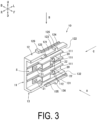
- FIG. 3 is a perspective view of a connector case 10 constituting the joint connector 4.
- FIG. 4 is a front view as seen from a direction of an arrow A in FIG. 3 .
- FIG. 5 is a plan view as seen from a direction of an arrow B in FIG. 3 .
- FIG. 6 is a side view as seen from a direction of an arrow C in FIG. 3 .
- FIG. 7 is a cross-sectional view taken along a direction of an arrow X-X in FIG. 6 .
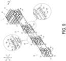
- FIGs. 8 and 9 are views illustrating assembly of the joint connector 4.
- the connector-equipped wire 1 is constituted by a plurality of flexible flat cables 2 and a plurality of covered cables 3 electrically connected via a joint connector 4.
- the flexible flat cable 2 and the covered cable 3 are one aspect of a wire.
- the joint connector 4 is formed by stacking connector cases 10.
- Each connector case 10 is made of a non-conductive synthetic resin and can accommodate a connection terminal 20.
- connection terminal 20 the connector case 10 and the connection terminal 20 will be described in detail.
- the connector case 10 includes a main plate part 11, an upper-side plate part 12, and a lower-side plate part 13.
- a space surrounded by the main plate part 11, the upper-side plate part 12, and the lower-side plate part 13 is referred to as an internal space S.
- the internal space S one to four connection terminals 20 can be accommodated.
- the main plate part 11 is formed in a substantially plate shape perpendicular to a front-rear direction of the joint connector 4.
- the main plate part 11 is provided with three inner-side plates 111 protruding toward the front side from an inner-side surface of the main plate part 11.
- the respective inner-side plates 111 are arranged in parallel with a left-right direction and at predetermined intervals in an upper-lower direction, and are formed to be highest (longest from the main plate part 11) at a middle portion in the left-right direction.
- An inner-side engaging piece 112 protruding to the left side is provided at a distal end portion of the respective inner-side plates 111.
- the main plate part 11 is provided with one outer-side plate 113 protruding toward the rear side from an outer-side surface of the main plate part 11.
- the outer-side plate 113 is arranged in parallel with the upper-lower direction on a slightly on the left side of the middle portion in the left-right direction, and is formed to have a constant height (a length from the main plate part 11).
- An outer-side engaging piece 114 protruding toward the right side is provided at a distal end portion of the outer-side plate 113. Note that only the outer-side plate 113 and the outer-side engaging piece 114 are parallel to the upper-lower direction, and contribute to suppression of flexural deformation in the main plate part 11.
- the upper-side plate part 12 is formed in a substantially plate shape perpendicular to the upper-lower direction of the joint connector 4.
- a distal end portion of the upper-side plate part 12 is provided with an extension portion 121 extending the upper-side plate part 12, between a left-side end face 12a (refer to FIGs. 4 and 5 ) and the middle portion.
- the extension portion 121 is formed in a rectangular shape with a constant thickness as seen from above.
- An engaging claw 122 protruding in a direction toward the opposing lower-side plate part 13 (a direction toward the lower side) is provided at a distal end portion of the extension portion 121.
- the engaging claw 122 is formed in parallel with the main plate part 11 from a left-side end face of the extension portion 121 (a left-side end face 12a of the upper-side plate part 12) to a right-side end face 12b (refer to FIG. 4 ).
- a proximal end portion of the upper-side plate part 12 is provided with a stepped portion 123 with an outer-side surface of the upper-side plate part 12 dug down, between the left-side end face 12a and the middle portion.
- the stepped portion 123 is formed in a rectangular shape with a constant depth as seen from above.
- an engaging groove 124 is provided recessed in a direction toward the opposing lower-side plate part 13 (a direction toward the lower side).
- the engaging groove 124 is formed in parallel with the main plate part 11 from a left-side end face of the stepped portion 123 (the left-side end face 12a of the upper-side plate part 12) to a right-side end face 12c (refer to FIG. 5 ). Note that the right-side end face of the engaging groove 124 is equal to the right-side end face 12c of the stepped portion 123.
- an inner-side surface of the upper-side plate part 12 is provided with a widened portion 125 protruding in the direction toward the opposing lower-side plate part 13 (a direction toward the lower side) between the left-side end face 12a of the upper-side plate part 12 and the middle portion.
- the widened portion 125 is formed in a rectangular shape with a constant thickness as seen from the front side.
- the widened portion 125 is formed to have a height (a length from the main plate part 11) equal to that of the upper-side plate part 12, and a distal end face 12d of the widened portion 125 (refer to FIGs. 4 and 6 ) is connected to a distal end face of the upper-side plate part 12 without a step. In this way, the distal end face 12d of the widened portion 125 is formed in parallel with and at a constant interval from the engaging claw 122.
- the outer-side surface of the upper-side plate part 12 is provided with two protrusion portions 126 protruding in a direction away from the opposing lower-side plate part 13 (a direction toward the upper side).
- One protrusion portion 126 is provided slightly on the left side of the middle portion in the left-right direction, and the other protrusion portion 126 is provided slightly on the right side of the middle portion in the left-right direction. Therefore, a band clamp 5 can be wound to extend between the protrusion portions 126 (refer to FIGs. 1 and 2 ).
- the protrusion portions 126 are formed in a rectangular shape as seen from above, but may also be formed in another shape.
- the protrusion portions 126 are formed in shapes equal to each other, they may also be formed in different shapes.
- the lower-side plate part 13 is formed in a substantially plate shape perpendicular to the upper-lower direction of the joint connector 4.
- a distal end portion of the lower-side plate part 13 is provided with an extension portion 131 extending the lower-side plate part 13, between a left-side end face 13a (refer to FIGs. 4 and 5 ) and the middle portion.
- the extension portion 131 is formed in a rectangular shape with a constant thickness as seen from below.
- An engaging claw 132 protruding in a direction toward the opposing upper-side plate part 12 (a direction toward the upper side) is provided at a distal end portion of the extension portion 131.
- the engaging claw 132 is formed in parallel with the main plate part 11 from a left-side end face of the extension portion 131 (a left-side end face 13a of the lower-side plate part 13) to a right-side end face 13b (refer to FIG. 4 ).
- a proximal end portion of the lower-side plate part 13 is provided with a stepped portion 133 with an outer-side surface of the lower-side plate part 13 dug down, between the left-side end face 13a and the middle portion.
- the stepped portion 133 is formed in a rectangular shape with a constant depth as seen from below.
- an engaging groove 134 is provided recessed in the direction toward the opposing upper-side plate part 12 (the direction toward the upper side).
- the engaging groove 134 is formed in parallel with the main plate part 11 from a left-side end face of the stepped portion 133 (the left-side end face 13a of the lower-side plate part 13) to a right-side end face 13c (refer to FIG. 5 ). Note that the right-side end face of the engaging groove 134 is equal to the right-side end face 13c of the stepped portion 133.
- an inner-side surface of the lower-side plate part 13 is provided with a widened portion 135 protruding in the direction toward the opposing upper-side plate part 12 (the direction toward the upper side) between the left-side end face 13a of the lower-side plate part 13 and the middle portion.
- the widened portion 135 is formed in a rectangular shape with a constant thickness as seen from the front side.
- the widened portion 135 is formed to have a height (a length from the main plate part 11) equal to that of the lower-side plate part 13, and a distal end face 13d of the widened portion 135 (refer to FIGs. 4 and 6 ) is connected to a distal end face of the lower-side plate part 13 without a step. In this way, the distal end face 13d of the widened portion 135 is formed in parallel with and at a constant interval from the engaging claw 132.
- the outer-side surface of the lower-side plate part 13 is provided with two protrusion portions 136 protruding in a direction away from the opposing upper-side plate part 12 (a direction toward the lower side).
- One protrusion portion 136 is provided slightly on the left side of the middle portion in the left-right direction, and the other protrusion portion 136 is provided slightly on the right side of the middle portion in the left-right direction. Therefore, the band clamp 5 can be wound to extend between the protrusion portions 136 (refer to FIGs. 1 and 2 ).
- the protrusion portions 136 are formed in a rectangular shape as seen from below, but may also be formed in another shape.
- the protrusion portions 136 are formed in shapes equal to each other, they may also be formed in different shapes.
- the connector cases are stacked with the engaging claws 122 and 132 of one connector case 10 and the engaging grooves 124 and 134 of another connector case 10 engaged with each other, respectively.
- the connector cases 10 can be firmly stacked.
- the connector cases 10 can be firmly stacked since the extension portions 121 and 131 and the stepped portions 123 and 133, which are relatively long, are fitted to each other over their entire lengths, the connector cases 10 can be firmly stacked.
- the inner-side plates 111 and the outer-side plate 113 come into contact with each other along the upper-lower direction perpendicular to the left-right direction. Therefore, the inner-side plates 111 and the outer-side plate 113 are restricted from moving to the left side or to the right side by each other, so that rattling of the stacked connector cases 10 can be suppressed.
- the inner-side engaging piece 112 and the outer-side engaging piece 114 are engaged with each other along the upper-lower direction perpendicular to the stacking direction. Therefore, the inner-side engaging piece 112 and the outer-side engaging piece 114 are restricted from moving toward each other or away from each other by each other, so that rattling of the stacked connector cases 10 can be suppressed.
- the right-side end faces of the engaging claws 122 and 132 of one connector case 10 and the right-side end faces of the engaging grooves 124 and 134 of the other connector case 10 are in contact with each other, respectively.
- the right-side end faces of the engaging claws 122 and 132 are equal to the right-side end faces 12c and 13c of the extension portions 121 and 131, respectively, and the right-side end faces of the engaging grooves 124 and 134 are equal to the right-side end faces 12c and 13c of the stepped portions 123 and 133, respectively, the right-side end faces 12b and 13b of the extension portions 121 and 131 of one connector case 10 and the right-side end faces 12c and 13c of the stepped portions 123 and 133 of the other connector case 10 are also in contact with each other, respectively. Therefore, the connector cases 10 can be stacked without misalignment.
- projections 115 are provided between the inner-side plate 111 and the inner-side plate 111 provided at the main plate part 11 and between the inner-side plate 111 and the widened portions 125 and 135, and the connection terminals 20 are held in a state of being fitted to the projections 115, respectively.
- the connection terminals 20 are held in parallel with the left-right direction.
- the inner-side plate 111 is arranged between two connection terminals 20 along the connection terminals 20.
- connection terminal 20 is provided with a piercing connection portion 21 at a right-side end portion thereof and a barrel connection portion 22 at a left-side end portion thereof (refer to FIGs. 2 and 3 ).
- the piercing connection portion 21 is electrically connected to the flexible flat cable 2 by crimping the flexible flat cable 2 penetrated by piercings (refer to FIG. 1 ).
- the barrel connection portion 22 is electrically connected to the covered cable 3 by crimping the covered cable 3 inserted in a barrel (see FIG. 1 ).
- connection terminal 20 can electrically connect the flexible flat cable 2 that is a wire on one side and the covered cable 3 that is a wire on the other side.
- each of the flexible flat cables 2 includes a plurality of conductors.
- the connector case 10 accommodating a plurality of the connection terminals 20 can electrically connect one flexible flat cable 2 and the plurality of covered cables 3.
- the joint connector 4 formed by stacking such connector cases 10 can electrically connect a plurality of flexible flat cables 2 and a plurality of covered cables 3 that are greater in number than that of the flexible flat cables.
- a direction from the front side to the rear side of the joint connector 4 is referred to as a stacking direction D.
- FIG. 8 illustrates steps of stacking the connector cases 10 by pushing the connector cases 10 to each other with the engaging claws 122 and 132 of one connector case 10 and the engaging grooves 124 and 134 of another connector case 10 overlapping each other in parallel, respectively.
- this step since the engaging claws 122 and 132 and the engaging grooves 124 and 134 are engaged with each other after the engaging claws 122 and 132 climb over end sides of the stepped portions 123 and 133, respectively, a moderate click feeling can be obtained.
- the connector cases 10 can be stacked without misalignment by aligning the right-side end faces of the engaging claws 122 and 132 and the right-side end faces of the engaging grooves 124 and 134 with positions where they come into contact with each other and pushing the connector cases.
- the connector case 10 since the right-side end faces of the engaging claws 122 and 132 and the right-side end faces of the extension portions 121 and 131 are equal to each other, respectively, and the right-side end faces of the engaging grooves 124 and 134 and the right-side end faces of the stepped portions 123 and 133 are also equal to each other, respectively, the connector cases 10 can be stacked without misalignment by aligning the right-side end faces of the extension portions 121 and 131 and the right-side end faces of the stepped portions 123 and 133 with positions where they come into contact with each other and pushing the connector cases.
- the joint connector 4 is formed by stacking the connector cases 10 accommodating the connection terminals 20.
- the connector case 10 includes the main plate part 11 that holds the connection terminals 20, and the pair of side plate parts (the upper-side plate part 12 and the lower-side plate part 13) perpendicular to the main plate part 11 and parallel to each other.
- the inner-side surfaces of the distal end portions of the respective side plate parts 12 and 13 are provided with the engaging claws 122 and 132 protruding in the direction toward the opposing side plate parts 12 and 13, respectively, and the outer-side surfaces of the proximal end portions of the respective side plate parts 12 and 13 are provided with the engaging grooves 124 and 134 recessed in the direction toward the opposing side plate parts 12 and 13, respectively.
- the connector cases are stacked with the engaging claws 122 and 132 of one connector case 10 and the engaging grooves 124 and 134 of another connector case 10 engaged with each other, respectively.
- the number of the connector cases 10 to be stacked is not limited, and the number of terminals can be easily and freely changed.
- the inner-side surfaces of the distal end portions of the respective side plate parts 12 and 13 are provided with the engaging claws 122 and 132 protruding in the directions toward the opposing side plate parts 12 and 13, respectively, and the outer-side surfaces of the proximal end portions of the respective side plate parts 12 and 13 are provided with the engaging grooves 124 and 134 recessed in the directions toward the opposing side plate parts 12 and 13, respectively.
- the connector cases are stacked with the engaging claws 122 and 132 of one connector case 10 and the engaging grooves 124 and 134 of another connector cases 10 engaged with each other, respectively.
- another connector case 10 can be stacked on the connector case 10 that is at the most distal end of the connector cases 10 constituting the joint connector 4.
- the connector cases 10 can be easily stacked by pushing the connector cases 10 to each other with the engaging claws 122 and 132 of one connector case 10 and the engaging grooves 124 and 134 of another connector case 10 overlapping each other in parallel, respectively. Therefore, the number of the connector cases 10 to be stacked is not limited, and the number of terminals can be easily and freely changed.
- the engaging claws 122 and 132 are provided, at the distal end portions of the respective side plate parts 12 and 13, between the left-side end faces 12a and 13a and the middle portions in the direction along the main plate part 11 and the side plate parts 12 and 13, respectively, and the engaging grooves 124 and 134 are provided, at the proximal end portions of the respective side plate parts 12 and 13, between the left-side end faces 12a and 13a and the middle portions in the direction along the main plate part 11 and the side plate parts 12 and 13, respectively.
- the right-side end faces 12b and 13b of the engaging claws 122 and 132 of one connector case 10 and the right-side end faces 12c and 13c of the engaging grooves 124 and 134 of another connector case 10 are stacked in a state of being in contact with each other.
- the connector cases 10 can be stacked without misalignment by aligning the right-side end faces 12b and 13b of the engaging claws 122 and 132 and the right-side end faces 12c and 13c of the engaging grooves 124 and 134 with positions where they come into contact with each other and pushing the connector cases.
- the engaging claws 122 and 132 and the engaging grooves 124 and 134 which are relatively long with respect to a length of one side of each of the side plate parts 12 and 13, are provided and mutually engaging lengths can be secured, the connector cases 10 can be firmly stacked. Further, since the mutually engaging lengths can be secured, rattling of the stacked connector cases 10 can be suppressed.
- the extension portions 121 and 131 including the engaging claws 122 and 132 are provided, at the distal end portions of the respective side plate parts 12 and 13, between the left-side end faces 12a and 13a and the middle portions in the direction along the main plate part 11 and the side plate parts 12 and 13, respectively, and the stepped portions 123 and 133 including the engaging grooves 124 and 134 are provided, at the proximal end portions of the respective side plate parts 12 and 13, between the left-side end faces 12a and 13a and the middle portions in the direction along the main plate part 11 and the side plate parts 12 and 13, respectively.
- the right-side end faces 12b and 13b of the extension portions 121 and 131 of one connector case 10 and the right-side end faces 12c and 13c of the stepped portions 123 and 133 of another connector case 10 are stacked in a state of being in contact with each other.
- the connector cases 10 can be stacked without misalignment by aligning the right-side end faces 12b and 13b of the extension portions 121 and 131 and the right-side end faces 12c and 13c of the stepped portions 123 and 133 with positions where they come into contact with each other and pushing the connector cases.
- the extension portions 121 and 131 and the stepped portions 123 and 133 which are relatively long with respect to the length of one side of each of the side plate parts 12 and 13, are provided and mutually fitting lengths can be secured, the connector cases 10 can be firmly stacked. Further, since the mutually fitting lengths can be secured, rattling of the stacked connector cases 10 can be suppressed.
- the inner-side plates 111 parallel to the side plate parts 12 and 13 are provided at the inner-side surface of the main plate part 11, and the outer-side plate 113 perpendicular to the side plate parts 12 and 13 is provided at the outer-side surface of the main plate part 11.
- the left-side end faces of the inner-side plates 111 of one connector case 10 and the right-side flat surface of the outer-side plate 113 of another connector case 10 are stacked in a state of being in contact with each other.
- the connector cases 10 can be stacked without misalignment by aligning the left-side end faces of the inner-side plates 111 and the right-side flat surface of the outer-side plate 113 with positions where they come into contact with each other and pushing the connector cases.
- the inner-side plates 111 and the outer-side plate 113 come into contact with each other perpendicularly to the engaging claws 122 and 132 and the engaging grooves 124 and 134 that engage from the left side to the right side, rattling of the stacked connector cases 10 can be suppressed.
- the inner-side engaging pieces 112 protruding to the left side are provided at the left-side end faces of the inner-side plates 111, and the outer-side engaging piece 114 protruding to the right side is provided at the right-side flat surface of the outer-side plate 113.
- the inner-side engaging piece 112 of one connector case 10 and the outer-side engaging piece 114 of another connector cases 10 are stacked in a state of being engaged with each other.
- the joint connector 4 since the inner-side engaging piece 112 of one connector case 10 and the outer-side engaging piece 114 of another connector case 10 are engaged with each other, rattling of the stacked connector cases 10 can be suppressed.
- rattling since the connector cases 10 are stacked in the stacking direction D, rattling may occur in the stacking direction D.
- the inner-side engaging piece 112 and the outer-side engaging piece 114 are engaged with each other along the upper-lower direction perpendicular to the stacking direction D, the inner-side engaging piece 112 and the outer-side engaging piece 114 are restricted from moving toward each other or away from each other by each other, so that rattling of the stacked connector cases 10 can be suppressed.
- connection terminals 20 are accommodated in the connector case 10 in parallel with the direction from the left side to the right side.
- the inner-side plate 111 that is non-conductive is arranged between two adjacent connection terminals 20 along the connection terminals 20.
- the inner-side plate 111 that is non-conductive is arranged between two adjacent connection terminals 20 along the connection terminals 20, it is possible to suppress short circuit between adjacent connection terminals 20.
- the inner-side plate 111 functions as a guide plate in the operation of accommodating the connection terminals 20 in the connector case 10, the operation is made easy.
- the inner-side surfaces of the respective side plate parts 12 and 13 are provided with the widened portions 125 and 135 protruding in the direction toward the opposing side plate parts 12 and 13, respectively.
- the distal end faces 12d and 13d of the widened portions 125 and 135 are formed in parallel with and at a constant interval from the engaging claws 122 and 132.
- the pushed main plate part 11 comes into contact with the distal end faces 12d and 13d of the widened portions 125 and 135 and is supported along the distal end faces 12d and 13d, so that the connector cases 10 can be stacked without inclination.
- the outer-side surfaces of the respective side plate parts 12 and 13 are provided with the protrusion portions 126 and 136 protruding in the direction away from the opposing side plate parts 12 and 13, respectively.
- the respective protrusion portions 126 and 136 of the stacked connector cases 10 form a guide passage for the band clamp 5.
- the stacked connector cases 10 can be bundled by using the band clamp 5.
- the stacked connector cases 10 can also be fixed to a fixing target by using the band clamp 5.
- the present invention relates to the connector-equipped wire 1 including the joint connector 4 according to the present invention and a wire (the flexible flat cable 2 and the covered cable 3) connected to the connection terminal 20 of the connector case 10 constituting the joint connector 4.
- joint connector 4 in the present invention is a concept encompassing all the joint connectors 4 according to the respective inventions described above.
- connection terminal 20 even when the specifications of a wire on one side (flexible flat cable 2) and a wire on the other side (covered cable 3) connected by the connection terminal 20 are different from each other, an electric cable can be formed in which these wires are electrically connected. In such an electric cable, loosening and entanglement of the wires 2 and 3 can be suppressed and the wires 2 and 3 can be bundled in a simplified manner.
- the wire on at least one side is the flexible flat cable 2.
- the flexible flat cable 2 in the present invention is a concept encompassing all cables in which conductors arranged in parallel are sandwiched between sheet-like insulators.
- an electric cable can be formed in which the flexible flat cable 2 and a wire (covered cable 3) having another specification are electrically connected.
- loosening and entanglement of the wires 2 and 3 can be suppressed and the wires 2 and 3 can be bundled in a simplified manner.
- the connector case 10 for accommodating the connection terminal 20 includes the main plate part 11 that holds the connection terminals 20 and the pair of side plate parts (the upper-side plate part 12 and the lower-side plate part 13) perpendicular to the main plate part 11 and parallel to each other, the inner-side surfaces of the distal end portions of the respective side plate parts 12 and 13 are provided with the engaging claws 122 and 132 protruding in the direction toward the opposing side plate parts 12 and 13, respectively, and the outer-side surfaces of the proximal end portions of the respective side plate parts 12 and 13 are provided with the engaging grooves 124 and 134 recessed in the direction toward the opposing side plate parts 12 and 13, respectively.
- the above-described effects can be obtained for the joint connector 4 formed by stacking the connector cases 10. That is, the number of the connector cases 10 to be stacked is not limited, and the number of terminals can be easily and freely changed.
- the connector-equipped wire of the present invention corresponds to the connector-equipped wire 1, and similarly, the wire corresponds to the flexible flat cable 2 and the covered cable 3, the joint connector corresponds to the joint connector 4, the connector case corresponds to the connector case 10, the main plate part corresponds to the main plate part 11, the side plate parts correspond to the upper-side plate part 12 and the lower-side plate part 13, the inner-side plate corresponds to the inner-side plate 111, the inner-side engaging piece corresponds to the inner-side engaging piece 112, the outer-side plate corresponds to the outer-side plate 113, the outer-side engaging piece corresponds to the outer-side engaging piece 114, the extension portion corresponds to the extension portion 121 and the extension portion 131, the engaging claw corresponds to the engaging claw 122 and the engaging claw 132, the stepped portion corresponds to the stepped portion 123 and the stepped portion 133, the engaging groove corresponds to the engaging groove 124 and the engaging groove 134, the widened portion corresponds
- the wire on one side to be electrically connected by the connection terminal 20 is the flexible flat cable 2, and the wire on the other side is the covered cable 3 having a circular cross-sectional shape.
- the flexible flat cables 2 may be connected on both sides by changing the connection terminal 20.
- the covered cables 3 may be connected on both sides.
- the connector cases 10 can be stacked by fitting to each other and sliding the engaging claws 122 and 132 of one connector case 10 and the engaging grooves 124 and 134 of another connector case 10 from a side (in the left-right direction).
- the outer-side plate 113 climbs over long sides of the inner-side plates 111, the left-side end faces of the inner-side plates 111 and the right-side flat surface of the outer-side plate 113 come into contact with each other and the inner-side engaging pieces 112 and the outer-side engaging piece 114 are engaged with each other, so that a moderate click feeling can be obtained.
- the connector cases 10 can be stacked without misalignment.
- the right-side end faces of the engaging claws 122 and 132 and the right-side end faces of the extension portions 121 and 131 are equal to each other, respectively, and the right-side end faces of the engaging grooves 124 and 134 and the right-side end faces of the stepped portions 123 and 133 are also equal to each other, respectively, the right-side end faces of the extension portions 121 and 131 and the right-side end faces of the stepped portions 123 and 133 come into contact with each other and stop at appropriate positions, respectively, so that the connector cases 10 can be stacked without misalignment.
Landscapes
- Connector Housings Or Holding Contact Members (AREA)
- Details Of Connecting Devices For Male And Female Coupling (AREA)
Abstract
Description
- The present invention relates to a joint connector, a connector-equipped wire, and a connector case.
- Conventionally, there have been known joint connectors formed by stacking connector cases accommodating connection terminals (refer to
Patent Documents 1 and 2). When such joint connectors are used, the number of terminals can be changed in accordance with the number of wires to be connected. - Incidentally, the joint connectors disclosed in these patent documents include a case holder for accommodating the stacked connector cases. Thus, the number of connector cases to be stacked is limited to the maximum number that can be accommodated in the case holder. Therefore, there has been a demand for a joint connector in which the number of connector cases to be stacked is not limited and the number of terminals can be easily and freely changed.
-
- Patent Document 1:
JP 2014-112497 A - Patent Document 2:
JP 2009-64735 A - An object of the present invention is to provide a joint connector in which the number of connector cases to be stacked is not limited and the number of terminals can be easily and freely changed.
- The present invention provides a joint connector formed by stacking connector cases each accommodating an h, wherein the connector cases each include a main plate part configured to hold the connection terminal, and a pair of side plate parts perpendicular to the main plate part and parallel to each other, an inner-side surface of a distal end portion of each of the pair of side plate parts is provided with an engaging claw protruding in a direction toward the opposing side plate part of the pair of side plate parts or an engaging groove recessed in a direction away from the opposing side plate part, an outer-side surface of a proximal end portion of each of the pair of side plate parts is provided with an engaging groove recessed in the direction toward the opposing side plate part or an engaging claw protruding in the direction away from the opposing side plate part, and the connector cases are stacked with the engaging claws of one of the connector cases and the engaging grooves of another of the connector cases engaged with each other, respectively.
- Note that the distal end portion of the side plate part means a distant side end portion of the side plate part distant from the main plate part, and the proximal end portion of the side plate part means a close side end portion of the side plate part close to the main plate part. Further, the inner-side surface means a wall surface on a side of the internal space in which the connection terminal is accommodated, and the outer-side surface means a wall surface on a side opposite to the internal space.
- According to the present invention, the number of connector cases to be stacked is not limited, and the number of terminals can be easily and freely changed.
- Specifically, in the joint connector according to the present invention, the inner-side surface of the distal end portion of each of the side plate parts is provided with the engaging claw protruding in the direction toward the opposing side plate part or the engaging groove recessed in the direction away from the opposing side plate part, and the outer-side surface of the proximal end portion of each of the side plate parts is provided with the engaging groove recessed in the direction toward the opposing side plate part or the engaging claw protruding in the direction away from the opposing side plate part. The connector cases are stacked with the engaging claws of one connector case and the engaging grooves of another connector case engaged with each other, respectively. For this reason, another connector case can be stacked on the connector case that is at the most distal end of the connector cases constituting the joint connector. In addition, the connector cases can be easily stacked by pushing the connector cases to each other with the engaging claws of one connector case and the engaging grooves of another connector case overlapping each other in parallel, respectively. Therefore, the number of connector cases to be stacked is not limited, and the number of terminals can be easily and freely changed.
- As an embodiment of the present invention, the engaging claw or the engaging groove may be provided, at the distal end portion of each of the side plate parts, between one side end face and a middle portion in a direction along the main plate part and the side plate parts, the engaging groove or the engaging claw may be provided, at the proximal end portion of each of the side plate parts, between the one side end face and the middle portion in the direction along the main plate part and the side plate parts, and the other side end faces of the engaging claws of one of the connector cases and the other side end faces of the engaging grooves of another of the connector cases may be stacked in a state of being in contact with each other.
- According to the present invention, in the operation of stacking the connector cases, the connector cases can be stacked without misalignment by aligning the other side end faces of the engaging claws and the other side end faces of the engaging grooves with positions where they come into contact with each other and pushing the connector cases. In addition, since the engaging claw and the engaging groove that are relatively long with respect to a length of one side of the side plate part are provided and a mutually engaging length can be secured, the connector cases can be firmly stacked. Further, since the mutually engaging length can be secured, rattling of the stacked connector cases can be suppressed.
- Further, as an embodiment of the present invention, an extension portion including the engaging claw or the engaging groove may be provided, at the distal end portion of each of the side plate parts, between one side end face and a middle portion in a direction along the main plate part and the side plate parts, a stepped portion including the engaging groove or the engaging claw may be provided, at the proximal end portion of each of the side plate parts, between the one side end face and the middle portion in the direction along the main plate part and the side plate parts, and the other side end faces of the extension portions of one of the connector cases and the other side end faces of the stepped portions of another of the connector cases may be stacked in a state of being in contact with each other.
- According to the present invention, in the operation of stacking the connector cases, the connector cases can be stacked without misalignment by aligning the other side end faces of the extension portions and the other side end faces of the stepped portions with positions where they come into contact with each other and pushing the connector cases. In addition, since the extension portion and the stepped portion that are relatively long with respect to a length of one side of the side plate part are provided and a mutually fitting length can be secured, the connector cases can be firmly stacked. Further, since the mutually engaging length can be secured, rattling of the stacked connector cases can be suppressed.
- Further, as an embodiment of the present invention, an inner-side plate parallel to the side plate parts may be provided at an inner-side surface of the main plate part, an outer-side plate perpendicular to the side plate parts may be provided at an outer-side surface of the main plate part, and one side end face of the inner-side plate of one of the connector cases and the other side flat surface of the outer-side plate of another of the connector cases may be stacked in a state of being in contact with each other.
- Note that the inner-side surface of the main plate part means a wall surface of the main plate part on a side of the internal space in which the connection terminal is accommodated, and the outer-side surface of the main plate part means a wall surface of the main plate part on a side opposite to the internal space.
- According to the present invention, in the operation of stacking the connector cases, the connector cases can be stacked without misalignment by aligning one side end face of the inner-side plate and the other side flat surface of the outer-side plate with positions where they come into contact with each other and pushing the connector cases. In addition, since the inner-side plate and the outer-side plate come into contact with each other perpendicularly to the engaging claws and the engaging grooves that engage from one side to the other side, rattling of the stacked connector cases can be suppressed. In this regard, to describe specifically, since the engaging claws and the engaging grooves are provided from one side to the other side, rattling may occur in this direction. However, since the inner-side plate and the outer-side plate come into contact with each other along a direction perpendicular to this direction, the inner-side plate and the outer-side plate are restricted from moving toward one side or the other side by each other, so that rattling of the stacked connector cases can be suppressed.
- Further, as an embodiment of the present invention, an inner-side engaging piece protruding toward one side may be provided at one side end face of the inner-side plate, an outer-side engaging piece protruding toward the other side may be provided at the other side flat surface of the outer-side plate, and the inner-side engaging piece of one of the connector cases and the outer-side engaging piece of another of the connector cases may be stacked in a state of being engaged with each other.
- According to the present invention, since the inner-side engaging piece of one connector case and the outer-side engaging piece of another connector case are engaged with each other, rattling of the stacked connector cases can be suppressed. In this regard, to describe specifically, since the connector cases are stacked in the stacking direction, rattling may occur in this direction. However, since the inner-side engaging piece and the outer-side engaging piece are engaged with each other along a direction perpendicular to this direction, the inner-side engaging piece and the outer-side engaging piece are restricted from moving toward each other or away from each other by each other, so that rattling of the stacked connector cases can be suppressed.
- Further, as an embodiment of the present invention, a plurality of the connection terminals may be accommodated in each of the connector cases in parallel with a direction from one side to the other side, and the inner-side plate that is non-conductive may be arranged between two adjacent connection terminals of the plurality of connection terminals and along the connection terminals.
- According to the present invention, since the inner-side plate that is non-conductive is arranged between two adjacent connection terminals and along the connection terminals, it is possible to suppress short circuit between adjacent connection terminals. In addition, since the inner-side plate functions as a guide plate in the operation of accommodating the connection terminals in the connector case, the operation is made easy.
- Further, as an embodiment of the present invention, an inner-side surface of each of the side plate parts may be provided with a widened portion protruding in a direction toward the opposing side plate part, and a distal end face of the widened portion may be formed in parallel with and at a constant interval from the engaging claw or the engaging groove.
- According to the present invention, in the operation of stacking the connector cases, the pushed main plate part comes into contact with the distal end faces of the widened portions and is supported along the distal end faces, so that the connector cases can be stacked without inclination.
- Further, as an embodiment of the present invention, an outer-side surface of each of the side plate parts may be provided with a protrusion portion protruding in a direction away from the opposing side plate part, and each of the protrusion portions in the connector cases stacked may constitute a guide passage for a band clamp.
- According to the present invention, misalignment or falling off of the band clamp wound along the protrusion portions can be suppressed. For this reason, the stacked connector cases can be bundled by using the band clamp. In addition, the stacked connector cases can also be fixed to a fixing target by using the band clamp.
- Further, as an embodiment of the present invention, there may be provided a connector-equipped wire including the joint connector according to the present invention and a wire connected to the connection terminal of each of the connector cases constituting the joint connector.
- Note that the joint connector in the present invention is a concept encompassing all the joint connectors according to the respective inventions described above.
- According to the present invention, even when the specifications of a wire on one side and a wire on the other side connected by the connection terminal are different from each other, an electric cable can be formed in which these are electrically connected. In such an electric cable, loosening and entanglement of the wires can be suppressed and the wires can be bundled in a simplified manner.
- Further, as an embodiment of the present invention, the wire on at least one side may be a flexible flat cable.
- Note that the flexible flat cable in the present invention is a concept encompassing all cables in which conductors arranged in parallel are sandwiched between sheet-like insulators.
- According to the present invention, an electric cable can be formed in which a flexible flat cable and a wire having another specification are electrically connected. In such an electric cable, loosening and entanglement of the wires can be suppressed and the wires can be bundled in a simplified manner.
- The present invention provides a connector case configured to accommodate a connection terminal, the connector case including a main plate part configured to hold the connection terminal, and a pair of side plate parts perpendicular to the main plate part and parallel to each other, wherein an inner-side surface of a distal end portion of each of the pair of side plate parts is provided with an engaging claw protruding in a direction toward an opposing side plate part of the pair of side plate parts or an engaging groove recessed in a direction away from the opposing side plate part, and an outer-side surface of a proximal end portion of each of the pair of side plate parts is provided with an engaging groove recessed in the direction toward the opposing side plate part or an engaging claw protruding in the direction away from the opposing side plate part.
- According to the present invention, the above-described effects can be obtained for the joint connector formed by stacking the connector cases. That is, the number of connector cases to be stacked is not limited, and the number of terminals can be easily and freely changed.
- According to the present invention, the number of connector cases to be stacked is not limited and the number of terminals can be easily and freely changed.
-
-
FIG. 1 is a perspective view of a connector-equipped wire. -
FIG. 2 is a perspective view of a joint connector constituting the connector-equipped wire. -
FIG. 3 is a perspective view of a connector case constituting the joint connector. -
FIG. 4 is a front view as seen from a direction of an arrow A inFIG. 3 . -
FIG. 5 is a plan view as seen from a direction of an arrow B inFIG. 3 . -
FIG. 6 is a side view as seen from a direction of an arrow C inFIG. 3 . -
FIG. 7 is a cross-sectional view taken along a direction of an arrow X-X inFIG. 6 . -
FIG. 8 is a view illustrating assembly of the joint connector. -
FIG. 9 is a view illustrating assembly of the joint connector. - An example of the present invention will be described in detail with reference to the drawings.
- In the present application, directions of a joint connector 4 are indicated in all figures. Specifically, an arrow F indicates the front side, an arrow B indicates the rear side, an arrow R indicates the right side, and an arrow L indicates the left side. An arrow U indicates the upper side, and an arrow D indicates the lower side.
-
FIG. 1 is a perspective view of a connector-equippedwire 1.FIG. 2 is a perspective view of a joint connector 4 constituting the connector-equippedwire 1.FIG. 3 is a perspective view of aconnector case 10 constituting the joint connector 4.FIG. 4 is a front view as seen from a direction of an arrow A inFIG. 3 .FIG. 5 is a plan view as seen from a direction of an arrow B inFIG. 3 .FIG. 6 is a side view as seen from a direction of an arrow C inFIG. 3 .FIG. 7 is a cross-sectional view taken along a direction of an arrow X-X inFIG. 6 .FIGs. 8 and9 are views illustrating assembly of the joint connector 4. - As illustrated in
FIG. 1 , the connector-equippedwire 1 is constituted by a plurality of flexibleflat cables 2 and a plurality of covered cables 3 electrically connected via a joint connector 4. The flexibleflat cable 2 and the covered cable 3 are one aspect of a wire. - As illustrated in
FIG. 2 , the joint connector 4 is formed by stackingconnector cases 10. Eachconnector case 10 is made of a non-conductive synthetic resin and can accommodate aconnection terminal 20. Hereinafter, theconnector case 10 and theconnection terminal 20 will be described in detail. - As illustrated in
FIGs. 3 to 7 , theconnector case 10 includes amain plate part 11, an upper-side plate part 12, and a lower-side plate part 13. In theconnector case 10 disclosed in the present application, a space surrounded by themain plate part 11, the upper-side plate part 12, and the lower-side plate part 13 is referred to as an internal space S. In the internal space S, one to fourconnection terminals 20 can be accommodated. - The
main plate part 11 is formed in a substantially plate shape perpendicular to a front-rear direction of the joint connector 4. Themain plate part 11 is provided with three inner-side plates 111 protruding toward the front side from an inner-side surface of themain plate part 11. The respective inner-side plates 111 are arranged in parallel with a left-right direction and at predetermined intervals in an upper-lower direction, and are formed to be highest (longest from the main plate part 11) at a middle portion in the left-right direction. An inner-sideengaging piece 112 protruding to the left side is provided at a distal end portion of the respective inner-side plates 111. - In addition, the
main plate part 11 is provided with one outer-side plate 113 protruding toward the rear side from an outer-side surface of themain plate part 11. The outer-side plate 113 is arranged in parallel with the upper-lower direction on a slightly on the left side of the middle portion in the left-right direction, and is formed to have a constant height (a length from the main plate part 11). An outer-sideengaging piece 114 protruding toward the right side is provided at a distal end portion of the outer-side plate 113. Note that only the outer-side plate 113 and the outer-sideengaging piece 114 are parallel to the upper-lower direction, and contribute to suppression of flexural deformation in themain plate part 11. - The upper-
side plate part 12 is formed in a substantially plate shape perpendicular to the upper-lower direction of the joint connector 4. A distal end portion of the upper-side plate part 12 is provided with anextension portion 121 extending the upper-side plate part 12, between a left-side end face 12a (refer toFIGs. 4 and5 ) and the middle portion. Theextension portion 121 is formed in a rectangular shape with a constant thickness as seen from above. Anengaging claw 122 protruding in a direction toward the opposing lower-side plate part 13 (a direction toward the lower side) is provided at a distal end portion of theextension portion 121. The engagingclaw 122 is formed in parallel with themain plate part 11 from a left-side end face of the extension portion 121 (a left-side end face 12a of the upper-side plate part 12) to a right-side end face 12b (refer toFIG. 4 ). - In addition, a proximal end portion of the upper-
side plate part 12 is provided with a steppedportion 123 with an outer-side surface of the upper-side plate part 12 dug down, between the left-side end face 12a and the middle portion. The steppedportion 123 is formed in a rectangular shape with a constant depth as seen from above. At a bottom surface of the steppedportion 123, an engaginggroove 124 is provided recessed in a direction toward the opposing lower-side plate part 13 (a direction toward the lower side). The engaginggroove 124 is formed in parallel with themain plate part 11 from a left-side end face of the stepped portion 123 (the left-side end face 12a of the upper-side plate part 12) to a right-side end face 12c (refer toFIG. 5 ). Note that the right-side end face of the engaginggroove 124 is equal to the right-side end face 12c of the steppedportion 123. - Further, an inner-side surface of the upper-
side plate part 12 is provided with a widenedportion 125 protruding in the direction toward the opposing lower-side plate part 13 (a direction toward the lower side) between the left-side end face 12a of the upper-side plate part 12 and the middle portion. The widenedportion 125 is formed in a rectangular shape with a constant thickness as seen from the front side. In addition, the widenedportion 125 is formed to have a height (a length from the main plate part 11) equal to that of the upper-side plate part 12, and adistal end face 12d of the widened portion 125 (refer toFIGs. 4 and6 ) is connected to a distal end face of the upper-side plate part 12 without a step. In this way, thedistal end face 12d of the widenedportion 125 is formed in parallel with and at a constant interval from the engagingclaw 122. - Additionally, the outer-side surface of the upper-
side plate part 12 is provided with twoprotrusion portions 126 protruding in a direction away from the opposing lower-side plate part 13 (a direction toward the upper side). Oneprotrusion portion 126 is provided slightly on the left side of the middle portion in the left-right direction, and theother protrusion portion 126 is provided slightly on the right side of the middle portion in the left-right direction. Therefore, aband clamp 5 can be wound to extend between the protrusion portions 126 (refer toFIGs. 1 and2 ). Note that theprotrusion portions 126 are formed in a rectangular shape as seen from above, but may also be formed in another shape. In addition, although theprotrusion portions 126 are formed in shapes equal to each other, they may also be formed in different shapes. - The lower-
side plate part 13 is formed in a substantially plate shape perpendicular to the upper-lower direction of the joint connector 4. A distal end portion of the lower-side plate part 13 is provided with anextension portion 131 extending the lower-side plate part 13, between a left-side end face 13a (refer toFIGs. 4 and5 ) and the middle portion. Theextension portion 131 is formed in a rectangular shape with a constant thickness as seen from below. Anengaging claw 132 protruding in a direction toward the opposing upper-side plate part 12 (a direction toward the upper side) is provided at a distal end portion of theextension portion 131. The engagingclaw 132 is formed in parallel with themain plate part 11 from a left-side end face of the extension portion 131 (a left-side end face 13a of the lower-side plate part 13) to a right-side end face 13b (refer toFIG. 4 ). - In addition, a proximal end portion of the lower-
side plate part 13 is provided with a steppedportion 133 with an outer-side surface of the lower-side plate part 13 dug down, between the left-side end face 13a and the middle portion. The steppedportion 133 is formed in a rectangular shape with a constant depth as seen from below. At a bottom surface of the steppedportion 133, an engaginggroove 134 is provided recessed in the direction toward the opposing upper-side plate part 12 (the direction toward the upper side). The engaginggroove 134 is formed in parallel with themain plate part 11 from a left-side end face of the stepped portion 133 (the left-side end face 13a of the lower-side plate part 13) to a right-side end face 13c (refer toFIG. 5 ). Note that the right-side end face of the engaginggroove 134 is equal to the right-side end face 13c of the steppedportion 133. - Further, an inner-side surface of the lower-
side plate part 13 is provided with a widenedportion 135 protruding in the direction toward the opposing upper-side plate part 12 (the direction toward the upper side) between the left-side end face 13a of the lower-side plate part 13 and the middle portion. The widenedportion 135 is formed in a rectangular shape with a constant thickness as seen from the front side. In addition, the widenedportion 135 is formed to have a height (a length from the main plate part 11) equal to that of the lower-side plate part 13, and adistal end face 13d of the widened portion 135 (refer toFIGs. 4 and6 ) is connected to a distal end face of the lower-side plate part 13 without a step. In this way, thedistal end face 13d of the widenedportion 135 is formed in parallel with and at a constant interval from the engagingclaw 132. - Additionally, the outer-side surface of the lower-
side plate part 13 is provided with twoprotrusion portions 136 protruding in a direction away from the opposing upper-side plate part 12 (a direction toward the lower side). Oneprotrusion portion 136 is provided slightly on the left side of the middle portion in the left-right direction, and theother protrusion portion 136 is provided slightly on the right side of the middle portion in the left-right direction. Therefore, theband clamp 5 can be wound to extend between the protrusion portions 136 (refer toFIGs. 1 and2 ). Note that theprotrusion portions 136 are formed in a rectangular shape as seen from below, but may also be formed in another shape. In addition, although theprotrusion portions 136 are formed in shapes equal to each other, they may also be formed in different shapes. - With such a configuration, the connector cases are stacked with the engaging
claws connector case 10 and the engaginggrooves connector case 10 engaged with each other, respectively. At this time, since the engagingclaws grooves connector case 10 in the left-right direction, are engaged with each other over their entire lengths, theconnector cases 10 can be firmly stacked. In addition, since theextension portions portions connector cases 10 can be firmly stacked. - Further, while the engaging
claws grooves side plates 111 and the outer-side plate 113 come into contact with each other along the upper-lower direction perpendicular to the left-right direction. Therefore, the inner-side plates 111 and the outer-side plate 113 are restricted from moving to the left side or to the right side by each other, so that rattling of the stackedconnector cases 10 can be suppressed. Further, while theconnector cases 10 are stacked in the stacking direction, the inner-sideengaging piece 112 and the outer-sideengaging piece 114 are engaged with each other along the upper-lower direction perpendicular to the stacking direction. Therefore, the inner-sideengaging piece 112 and the outer-sideengaging piece 114 are restricted from moving toward each other or away from each other by each other, so that rattling of the stackedconnector cases 10 can be suppressed. - Additionally, in a state where the two
connector cases 10 are stacked, the right-side end faces of the engagingclaws connector case 10 and the right-side end faces of the engaginggrooves other connector case 10 are in contact with each other, respectively. Since the right-side end faces of the engagingclaws extension portions grooves portions extension portions connector case 10 and the right-side end faces 12c and 13c of the steppedportions other connector case 10 are also in contact with each other, respectively. Therefore, theconnector cases 10 can be stacked without misalignment. - Incidentally,
projections 115 are provided between the inner-side plate 111 and the inner-side plate 111 provided at themain plate part 11 and between the inner-side plate 111 and the widenedportions connection terminals 20 are held in a state of being fitted to theprojections 115, respectively. Theconnection terminals 20 are held in parallel with the left-right direction. At a location where theconnection terminals 20 are held adjacent to each other, the inner-side plate 111 is arranged between twoconnection terminals 20 along theconnection terminals 20. - In addition, the
connection terminal 20 is provided with a piercingconnection portion 21 at a right-side end portion thereof and abarrel connection portion 22 at a left-side end portion thereof (refer toFIGs. 2 and3 ). The piercingconnection portion 21 is electrically connected to the flexibleflat cable 2 by crimping the flexibleflat cable 2 penetrated by piercings (refer toFIG. 1 ). In addition, thebarrel connection portion 22 is electrically connected to the covered cable 3 by crimping the covered cable 3 inserted in a barrel (seeFIG. 1 ). - With such a configuration, the
connection terminal 20 can electrically connect the flexibleflat cable 2 that is a wire on one side and the covered cable 3 that is a wire on the other side. Note that each of the flexibleflat cables 2 includes a plurality of conductors. For this reason, theconnector case 10 accommodating a plurality of theconnection terminals 20 can electrically connect one flexibleflat cable 2 and the plurality of covered cables 3. In addition, the joint connector 4 formed by stackingsuch connector cases 10 can electrically connect a plurality of flexibleflat cables 2 and a plurality of covered cables 3 that are greater in number than that of the flexible flat cables. - Next, an assembly step for the joint connector 4 in which the
connector cases 10 accommodating theconnection terminals 20 are stacked will be described with reference toFIG. 8 . In the following description, a direction from the front side to the rear side of the joint connector 4 is referred to as a stacking direction D. -
FIG. 8 illustrates steps of stacking theconnector cases 10 by pushing theconnector cases 10 to each other with the engagingclaws connector case 10 and the engaginggrooves connector case 10 overlapping each other in parallel, respectively. In this step, since the engagingclaws grooves claws portions - In addition, the
connector cases 10 can be stacked without misalignment by aligning the right-side end faces of the engagingclaws grooves connector case 10, since the right-side end faces of the engagingclaws extension portions grooves portions connector cases 10 can be stacked without misalignment by aligning the right-side end faces of theextension portions portions - As described above, the joint connector 4 is formed by stacking the
connector cases 10 accommodating theconnection terminals 20. Theconnector case 10 includes themain plate part 11 that holds theconnection terminals 20, and the pair of side plate parts (the upper-side plate part 12 and the lower-side plate part 13) perpendicular to themain plate part 11 and parallel to each other. The inner-side surfaces of the distal end portions of the respectiveside plate parts claws side plate parts side plate parts grooves side plate parts claws connector case 10 and the engaginggrooves connector case 10 engaged with each other, respectively. - According to such a joint connector 4, the number of the
connector cases 10 to be stacked is not limited, and the number of terminals can be easily and freely changed. - Specifically, in the joint connector 4 according to the present invention, the inner-side surfaces of the distal end portions of the respective
side plate parts claws side plate parts side plate parts grooves side plate parts claws connector case 10 and the engaginggrooves connector cases 10 engaged with each other, respectively. For this reason, anotherconnector case 10 can be stacked on theconnector case 10 that is at the most distal end of theconnector cases 10 constituting the joint connector 4. In addition, theconnector cases 10 can be easily stacked by pushing theconnector cases 10 to each other with the engagingclaws connector case 10 and the engaginggrooves connector case 10 overlapping each other in parallel, respectively. Therefore, the number of theconnector cases 10 to be stacked is not limited, and the number of terminals can be easily and freely changed. - In addition, in the joint connector 4, the engaging
claws side plate parts main plate part 11 and theside plate parts grooves side plate parts main plate part 11 and theside plate parts claws connector case 10 and the right-side end faces 12c and 13c of the engaginggrooves connector case 10 are stacked in a state of being in contact with each other. - According to the joint connector 4, in the operation of stacking the
connector cases 10, theconnector cases 10 can be stacked without misalignment by aligning the right-side end faces 12b and 13b of the engagingclaws grooves claws grooves side plate parts connector cases 10 can be firmly stacked. Further, since the mutually engaging lengths can be secured, rattling of the stackedconnector cases 10 can be suppressed. - In addition, in the joint connector 4, the
extension portions claws side plate parts main plate part 11 and theside plate parts portions grooves side plate parts main plate part 11 and theside plate parts extension portions connector case 10 and the right-side end faces 12c and 13c of the steppedportions connector case 10 are stacked in a state of being in contact with each other. - According to the joint connector 4, in the operation of stacking the
connector cases 10, theconnector cases 10 can be stacked without misalignment by aligning the right-side end faces 12b and 13b of theextension portions portions extension portions portions side plate parts connector cases 10 can be firmly stacked. Further, since the mutually fitting lengths can be secured, rattling of the stackedconnector cases 10 can be suppressed. - In addition, in the joint connector 4, the inner-
side plates 111 parallel to theside plate parts main plate part 11, and the outer-side plate 113 perpendicular to theside plate parts main plate part 11. The left-side end faces of the inner-side plates 111 of oneconnector case 10 and the right-side flat surface of the outer-side plate 113 of anotherconnector case 10 are stacked in a state of being in contact with each other. - According to the joint connector 4, in the operation of stacking the
connector cases 10, theconnector cases 10 can be stacked without misalignment by aligning the left-side end faces of the inner-side plates 111 and the right-side flat surface of the outer-side plate 113 with positions where they come into contact with each other and pushing the connector cases. In addition, since the inner-side plates 111 and the outer-side plate 113 come into contact with each other perpendicularly to the engagingclaws grooves connector cases 10 can be suppressed. In this regard, to describe specifically, since the engagingclaws grooves side plates 111 and the outer-side plate 113 come into contact with each other along the upper-lower direction perpendicular to the left-right direction, the inner-side plates 111 and the outer-side plate 113 are restricted from moving to the left side or to the right side by each other, so that rattling of the stackedconnector cases 10 can be suppressed. - In addition, in the joint connector 4, the inner-
side engaging pieces 112 protruding to the left side are provided at the left-side end faces of the inner-side plates 111, and the outer-sideengaging piece 114 protruding to the right side is provided at the right-side flat surface of the outer-side plate 113. The inner-sideengaging piece 112 of oneconnector case 10 and the outer-sideengaging piece 114 of anotherconnector cases 10 are stacked in a state of being engaged with each other. - According to the joint connector 4, since the inner-side
engaging piece 112 of oneconnector case 10 and the outer-sideengaging piece 114 of anotherconnector case 10 are engaged with each other, rattling of the stackedconnector cases 10 can be suppressed. In this regard, to describe specifically, since theconnector cases 10 are stacked in the stacking direction D, rattling may occur in the stacking direction D. However, since the inner-sideengaging piece 112 and the outer-sideengaging piece 114 are engaged with each other along the upper-lower direction perpendicular to the stacking direction D, the inner-sideengaging piece 112 and the outer-sideengaging piece 114 are restricted from moving toward each other or away from each other by each other, so that rattling of the stackedconnector cases 10 can be suppressed. - In addition, in the joint connector 4, the plurality of
connection terminals 20 are accommodated in theconnector case 10 in parallel with the direction from the left side to the right side. The inner-side plate 111 that is non-conductive is arranged between twoadjacent connection terminals 20 along theconnection terminals 20. - According to the joint connector 4, since the inner-
side plate 111 that is non-conductive is arranged between twoadjacent connection terminals 20 along theconnection terminals 20, it is possible to suppress short circuit betweenadjacent connection terminals 20. In addition, since the inner-side plate 111 functions as a guide plate in the operation of accommodating theconnection terminals 20 in theconnector case 10, the operation is made easy. - Further, in the joint connector 4, the inner-side surfaces of the respective
side plate parts portions side plate parts portions claws - According to the joint connector 4, in the operation of stacking the
connector cases 10, the pushedmain plate part 11 comes into contact with the distal end faces 12d and 13d of the widenedportions connector cases 10 can be stacked without inclination. - Further, in the joint connector 4, the outer-side surfaces of the respective
side plate parts protrusion portions side plate parts respective protrusion portions connector cases 10 form a guide passage for theband clamp 5. - According to the joint connector 4, misalignment or falling off of the
band clamp 5 wound along theprotrusion portions connector cases 10 can be bundled by using theband clamp 5. In addition, the stackedconnector cases 10 can also be fixed to a fixing target by using theband clamp 5. - In addition, the present invention relates to the connector-equipped
wire 1 including the joint connector 4 according to the present invention and a wire (the flexibleflat cable 2 and the covered cable 3) connected to theconnection terminal 20 of theconnector case 10 constituting the joint connector 4. - Note that the joint connector 4 in the present invention is a concept encompassing all the joint connectors 4 according to the respective inventions described above.
- According to the connector-equipped
wire 1, even when the specifications of a wire on one side (flexible flat cable 2) and a wire on the other side (covered cable 3) connected by theconnection terminal 20 are different from each other, an electric cable can be formed in which these wires are electrically connected. In such an electric cable, loosening and entanglement of thewires 2 and 3 can be suppressed and thewires 2 and 3 can be bundled in a simplified manner. - In addition, in the connector-equipped
wire 1, the wire on at least one side is the flexibleflat cable 2. - Note that the flexible
flat cable 2 in the present invention is a concept encompassing all cables in which conductors arranged in parallel are sandwiched between sheet-like insulators. - According to the connector-equipped
wire 1, an electric cable can be formed in which the flexibleflat cable 2 and a wire (covered cable 3) having another specification are electrically connected. In such an electric cable, loosening and entanglement of thewires 2 and 3 can be suppressed and thewires 2 and 3 can be bundled in a simplified manner. - Further, the
connector case 10 for accommodating theconnection terminal 20 includes themain plate part 11 that holds theconnection terminals 20 and the pair of side plate parts (the upper-side plate part 12 and the lower-side plate part 13) perpendicular to themain plate part 11 and parallel to each other, the inner-side surfaces of the distal end portions of the respectiveside plate parts claws side plate parts side plate parts grooves side plate parts - According to the
connector case 10, the above-described effects can be obtained for the joint connector 4 formed by stacking theconnector cases 10. That is, the number of theconnector cases 10 to be stacked is not limited, and the number of terminals can be easily and freely changed. - In correspondence between the configuration of the present invention and the above-described embodiment, the connector-equipped wire of the present invention corresponds to the connector-equipped wire 1, and similarly, the wire corresponds to the flexible flat cable 2 and the covered cable 3, the joint connector corresponds to the joint connector 4, the connector case corresponds to the connector case 10, the main plate part corresponds to the main plate part 11, the side plate parts correspond to the upper-side plate part 12 and the lower-side plate part 13, the inner-side plate corresponds to the inner-side plate 111, the inner-side engaging piece corresponds to the inner-side engaging piece 112, the outer-side plate corresponds to the outer-side plate 113, the outer-side engaging piece corresponds to the outer-side engaging piece 114, the extension portion corresponds to the extension portion 121 and the extension portion 131, the engaging claw corresponds to the engaging claw 122 and the engaging claw 132, the stepped portion corresponds to the stepped portion 123 and the stepped portion 133, the engaging groove corresponds to the engaging groove 124 and the engaging groove 134, the widened portion corresponds to the widened portion 125 and the widened portion 135, the protrusion portion corresponds to the protrusion portion 126 and the protrusion portion 136, the connection terminal corresponds to the connection terminal 20, and the stacking direction corresponds to the stacking direction D. However, the present invention is not limited to only the configuration of the above-described embodiment, and many embodiments can be obtained.
- For example, in the joint connector 4 disclosed in the present application, the wire on one side to be electrically connected by the
connection terminal 20 is the flexibleflat cable 2, and the wire on the other side is the covered cable 3 having a circular cross-sectional shape. However, the flexibleflat cables 2 may be connected on both sides by changing theconnection terminal 20. Alternatively, the covered cables 3 may be connected on both sides. - Furthermore, as illustrated in
FIG. 9 , in the joint connector 4 disclosed in the present application, theconnector cases 10 can be stacked by fitting to each other and sliding the engagingclaws connector case 10 and the engaginggrooves connector case 10 from a side (in the left-right direction). In this step, after the outer-side plate 113 climbs over long sides of the inner-side plates 111, the left-side end faces of the inner-side plates 111 and the right-side flat surface of the outer-side plate 113 come into contact with each other and the inner-side engaging pieces 112 and the outer-sideengaging piece 114 are engaged with each other, so that a moderate click feeling can be obtained. - Further, since the right-side end faces of the engaging
claws grooves connector cases 10 can be stacked without misalignment. In this regard, in theconnector case 10, since the right-side end faces of the engagingclaws extension portions grooves portions extension portions portions connector cases 10 can be stacked without misalignment. -
- 1: Connector-equipped wire
- 2: Flexible flat cable
- 3: Covered cable
- 4: Joint connector
- 10: Connector case
- 11: Main plate part
- 12: Upper-side plate part
- 13: Lower-side plate part
- 111: Inner-side plate
- 112: Inner-side engaging piece
- 113: Outer-side plate
- 114: Outer-side engaging piece
- 121: Extension portion
- 122: Engaging claw
- 123: Stepped portion
- 124: Engaging groove
- 125: Widened portion
- 126: Protrusion portion
- 131: Extension portion
- 132: Engaging claw
- 133: Stepped portion
- 134: Engaging groove
- 135: Widened portion
- 136: Protrusion portion
- 20: Connection terminal
- D: Stacking direction
Claims (11)
- A joint connector formed by stacking connector cases each accommodating a connection terminal, wherein
the connector cases each comprise:a main plate part configured to hold the connection terminal, anda pair of side plate parts perpendicular to the main plate part and parallel to each other,an inner-side surface of a distal end portion of each of the pair of side plate parts is provided with an engaging claw protruding in a direction toward an opposing side plate part of the pair of side plate parts or an engaging groove recessed in a direction away from the opposing side plate part,an outer-side surface of a proximal end portion of each of the pair of side plate parts is provided with an engaging groove recessed in a direction toward the opposing side plate part or an engaging claw protruding in a direction away from the opposing side plate part, andthe connector cases are stacked with the engaging claws of one of the connector cases and the engaging grooves of another of the connector cases engaged with each other, respectively. - The joint connector according to claim 1, whereinthe engaging claw or the engaging groove is provided, at the distal end portion of each of the side plate parts, between one side end face and a middle portion in a direction along the main plate part and the side plate parts,the engaging groove or the engaging claw is provided, at the proximal end portion of each of the side plate parts, between the one side end face and the middle portion in the direction along the main plate part and the side plate parts, andthe other side end faces of the engaging claws of one of the connector cases and the other side end faces of the engaging grooves of another of the connector cases are stacked in a state of being in contact with each other.
- The joint connector according to claim 1 or 2, whereinan extension portion comprising the engaging claw or the engaging groove is provided, at the distal end portion of each of the side plate parts, between one side end face and a middle portion in a direction along the main plate part and the side plate parts,a stepped portion comprising the engaging groove or the engaging claw is provided, at the proximal end portion of each of the side plate parts, between the one side end face and the middle portion in the direction along the main plate part and the side plate parts, andthe other side end faces of the extension portions of one of the connector cases and the other side end faces of the stepped portions of another of the connector cases are stacked in a state of being in contact with each other.
- The joint connector according to any one of claims 1 to 3, whereinan inner-side plate parallel to the side plate parts is provided at an inner-side surface of the main plate part,an outer-side plate perpendicular to the side plate parts is provided at an outer-side surface of the main plate part, andone side end face of the inner-side plate of one of the connector cases and the other side flat surface of the outer-side plate of another of the connector cases are stacked in a state of being in contact with each other.
- The joint connector according to claim 4, whereinan inner-side engaging piece protruding toward one side is provided at the one side end face of the inner-side plate,an outer-side engaging piece protruding toward the other side is provided at the other side flat surface of the outer-side plate, andthe inner-side engaging piece of one of the connector cases and the outer-side engaging piece of another of the connector cases are stacked in a state of being engaged with each other.
- The joint connector according to claim 4 or 5, whereina plurality of the connection terminals are accommodated in each of the connector cases in parallel with a direction from one side to the other side, andthe inner-side plate that is non-conductive is arranged between two adjacent connection terminals of the plurality of connection terminals and along the connection terminals.
- The joint connector according to any one of claims 1 to 6, whereinan inner-side surface of each of the side plate parts is provided with a widened portion protruding in the direction toward the opposing side plate part, anda distal end face of the widened portion is opposed to the engaging claw or the engaging groove with the distal end face of the widened portion being in parallel with and at a constant interval from the engaging claw or the engaging groove.
- The joint connector according to any one of claims 1 to 7, whereinan outer-side surface of each of the side plate parts is provided with a protrusion portion protruding in the direction away from the opposing side plate part, andeach of the protrusion portions in the connector cases stacked constitutes a guide passage for a band clamp.
- A connector-equipped wire comprising:the joint connector according to any one of claims 1 to 8; anda wire connected to the connection terminal of each of the connector cases constituting the joint connector.
- The connector-equipped wire according to claim 9, wherein
the wire on at least one side is a flexible flat cable. - A connector case configured to accommodate a connection terminal, the connector case comprising:a main plate part configured to hold the connection terminal; anda pair of side plate parts perpendicular to the main plate part and parallel to each other, whereinan inner-side surface of a distal end portion of each of the pair of side plate parts is provided with an engaging claw protruding in a direction toward an opposing side plate part of the pair of side plate parts or an engaging groove recessed in a direction away from the opposing side plate part, andan outer-side surface of a proximal end portion of each of the pair of side plate parts is provided with an engaging groove recessed in the direction toward the opposing side plate part or an engaging claw protruding in the direction away from the opposing side plate part.
Applications Claiming Priority (2)
| Application Number | Priority Date | Filing Date | Title |
|---|---|---|---|
| JP2021048749 | 2021-03-23 | ||
| PCT/JP2022/009073 WO2022202183A1 (en) | 2021-03-23 | 2022-03-03 | Joint connector, connector-equipped electric wire, and connector case |
Publications (2)
| Publication Number | Publication Date |
|---|---|
| EP4318824A1 true EP4318824A1 (en) | 2024-02-07 |
| EP4318824A4 EP4318824A4 (en) | 2025-03-12 |
Family
ID=83396939
Family Applications (1)
| Application Number | Title | Priority Date | Filing Date |
|---|---|---|---|
| EP22774979.3A Pending EP4318824A4 (en) | 2021-03-23 | 2022-03-03 | JUNCTION CONNECTOR, ELECTRICAL WIRE EQUIPPED WITH CONNECTOR AND CONNECTOR HOUSING |
Country Status (6)
| Country | Link |
|---|---|
| US (1) | US20240006801A1 (en) |
| EP (1) | EP4318824A4 (en) |
| JP (1) | JP7214934B1 (en) |
| KR (1) | KR102903813B1 (en) |
| CN (1) | CN117044045A (en) |
| WO (1) | WO2022202183A1 (en) |
Family Cites Families (14)
| Publication number | Priority date | Publication date | Assignee | Title |
|---|---|---|---|---|
| JPH02148583A (en) * | 1988-11-29 | 1990-06-07 | Yazaki Corp | multi-stage connector |
| JP2555733Y2 (en) * | 1991-12-25 | 1997-11-26 | 住友電装株式会社 | connector |
| JP2518968Y2 (en) * | 1992-02-06 | 1996-12-04 | 矢崎総業株式会社 | Combined connector |
| JP3530046B2 (en) * | 1998-11-13 | 2004-05-24 | 矢崎総業株式会社 | Joint connector |
| JP3494917B2 (en) * | 1999-03-31 | 2004-02-09 | 矢崎総業株式会社 | ID connector |
| JP2002033154A (en) * | 2000-07-17 | 2002-01-31 | Yazaki Corp | Joint connector |
| JP3879057B2 (en) * | 2001-03-30 | 2007-02-07 | 住友電装株式会社 | Joint connector |
| JP2006294386A (en) * | 2005-04-08 | 2006-10-26 | Tyco Electronics Amp Kk | Electric connector, wire harness and method for wire harness arrangement |
| JP4809818B2 (en) | 2007-09-07 | 2011-11-09 | 古河電気工業株式会社 | connector |
| JP5730842B2 (en) | 2012-12-05 | 2015-06-10 | 古河電気工業株式会社 | Joint connector |
| CN105684222B (en) * | 2013-11-06 | 2019-07-09 | 古河电气工业株式会社 | Terminal blocks and wire assemblies |
| JP6222574B2 (en) * | 2014-11-28 | 2017-11-01 | 住友電装株式会社 | connector |
| JP6599151B2 (en) * | 2015-07-23 | 2019-10-30 | 矢崎総業株式会社 | Backlash structure of multilayer connector |
| JP6533242B2 (en) | 2017-02-22 | 2019-06-19 | タイコエレクトロニクスジャパン合同会社 | Connector unit |
-
2022
- 2022-03-03 CN CN202280022893.2A patent/CN117044045A/en active Pending
- 2022-03-03 KR KR1020237033242A patent/KR102903813B1/en active Active
- 2022-03-03 EP EP22774979.3A patent/EP4318824A4/en active Pending
- 2022-03-03 WO PCT/JP2022/009073 patent/WO2022202183A1/en not_active Ceased
- 2022-03-03 JP JP2022564584A patent/JP7214934B1/en active Active
-
2023
- 2023-09-19 US US18/469,612 patent/US20240006801A1/en active Pending
Also Published As
| Publication number | Publication date |
|---|---|
| KR20230150372A (en) | 2023-10-30 |
| JPWO2022202183A1 (en) | 2022-09-29 |
| US20240006801A1 (en) | 2024-01-04 |
| CN117044045A (en) | 2023-11-10 |
| WO2022202183A1 (en) | 2022-09-29 |
| KR102903813B1 (en) | 2025-12-26 |
| EP4318824A4 (en) | 2025-03-12 |
| JP7214934B1 (en) | 2023-01-30 |
Similar Documents
| Publication | Publication Date | Title |
|---|---|---|
| US8721350B2 (en) | Electrical connector and electrical connector assembly | |
| EP0112713B1 (en) | Shielded electrical connector | |
| US4963102A (en) | Electrical connector of the hermaphroditic type | |
| US4653836A (en) | Shielded electrical connector | |
| EP3061161B1 (en) | Electrical cable connector | |
| US9608353B1 (en) | Conductive terminal and electrical connector assembly | |
| US10525906B2 (en) | Branch structure and wire harness | |
| US9039463B2 (en) | Connector and wire harness | |
| USRE32760E (en) | Electrical connector | |
| EP0390450A1 (en) | Back-to-back stackable connector for interface bus | |
| JP5682997B2 (en) | Electrical connector | |
| CN117595020A (en) | Plug connector for an electrical plug connection and electrical plug connection formed therefrom | |
| CN112005442B (en) | Shielded plug connector module for a modular industrial plug connector | |
| EP0112711A1 (en) | Shunt-protected electrical connector | |
| JP2024177529A (en) | connector | |
| US12244086B2 (en) | Polarized connector for flat cable | |
| US20230056542A1 (en) | Connector For A Flat Flexible Cable | |
| US8263865B2 (en) | Wire connection unit | |
| CN1177419A (en) | Electrical connector with terminal support walls | |
| US20080090460A1 (en) | Electrical connector which has a wire aligning function and which can be reduced in size | |
| US20240006801A1 (en) | Joint connector, connector-equipped wire, and connector case | |
| US7070442B2 (en) | Structure for press-connecting sheathed electric wire with terminal | |
| US8550841B2 (en) | Flat cable connector having cable support structure | |
| US20230208061A1 (en) | Connector Having a Housing with a Window | |
| EP3809529A1 (en) | Connector |
Legal Events
| Date | Code | Title | Description |
|---|---|---|---|
| STAA | Information on the status of an ep patent application or granted ep patent |
Free format text: STATUS: THE INTERNATIONAL PUBLICATION HAS BEEN MADE |
|
| PUAI | Public reference made under article 153(3) epc to a published international application that has entered the european phase |
Free format text: ORIGINAL CODE: 0009012 |
|
| STAA | Information on the status of an ep patent application or granted ep patent |
Free format text: STATUS: REQUEST FOR EXAMINATION WAS MADE |
|
| 17P | Request for examination filed |
Effective date: 20231023 |
|
| AK | Designated contracting states |
Kind code of ref document: A1 Designated state(s): AL AT BE BG CH CY CZ DE DK EE ES FI FR GB GR HR HU IE IS IT LI LT LU LV MC MK MT NL NO PL PT RO RS SE SI SK SM TR |
|
| DAV | Request for validation of the european patent (deleted) | ||
| DAX | Request for extension of the european patent (deleted) | ||
| A4 | Supplementary search report drawn up and despatched |
Effective date: 20250205 |
|
| RIC1 | Information provided on ipc code assigned before grant |
Ipc: H01R 12/69 20110101ALN20250131BHEP Ipc: H01R 12/63 20110101ALN20250131BHEP Ipc: H01R 11/05 20060101ALN20250131BHEP Ipc: H01R 4/18 20060101ALN20250131BHEP Ipc: H01R 13/508 20060101ALI20250131BHEP Ipc: H01R 13/514 20060101ALI20250131BHEP Ipc: H01R 31/08 20060101AFI20250131BHEP |