EP4318799A1 - On-vehicle antenna device - Google Patents
On-vehicle antenna device Download PDFInfo
- Publication number
- EP4318799A1 EP4318799A1 EP22780910.0A EP22780910A EP4318799A1 EP 4318799 A1 EP4318799 A1 EP 4318799A1 EP 22780910 A EP22780910 A EP 22780910A EP 4318799 A1 EP4318799 A1 EP 4318799A1
- Authority
- EP
- European Patent Office
- Prior art keywords
- antenna
- vehicular
- case
- antenna device
- antennas
- Prior art date
- Legal status (The legal status is an assumption and is not a legal conclusion. Google has not performed a legal analysis and makes no representation as to the accuracy of the status listed.)
- Pending
Links
- 230000004308 accommodation Effects 0.000 claims abstract description 16
- 239000000758 substrate Substances 0.000 claims description 97
- 239000002184 metal Substances 0.000 description 94
- 229910052751 metal Inorganic materials 0.000 description 94
- 230000003071 parasitic effect Effects 0.000 description 69
- 238000010586 diagram Methods 0.000 description 43
- 239000004020 conductor Substances 0.000 description 13
- 230000005855 radiation Effects 0.000 description 13
- 230000005404 monopole Effects 0.000 description 12
- 238000000926 separation method Methods 0.000 description 12
- 238000004891 communication Methods 0.000 description 8
- 230000007423 decrease Effects 0.000 description 8
- 238000009434 installation Methods 0.000 description 8
- 230000000694 effects Effects 0.000 description 7
- 229920005989 resin Polymers 0.000 description 7
- 239000011347 resin Substances 0.000 description 7
- 238000004364 calculation method Methods 0.000 description 4
- 238000010295 mobile communication Methods 0.000 description 4
- 230000009467 reduction Effects 0.000 description 4
- 238000004381 surface treatment Methods 0.000 description 4
- 238000005452 bending Methods 0.000 description 3
- 239000002131 composite material Substances 0.000 description 3
- 239000000463 material Substances 0.000 description 3
- 238000004088 simulation Methods 0.000 description 3
- PCHJSUWPFVWCPO-UHFFFAOYSA-N gold Chemical compound [Au] PCHJSUWPFVWCPO-UHFFFAOYSA-N 0.000 description 2
- 239000010931 gold Substances 0.000 description 2
- 229910052737 gold Inorganic materials 0.000 description 2
- 239000011796 hollow space material Substances 0.000 description 2
- 238000007747 plating Methods 0.000 description 2
- 229910000679 solder Inorganic materials 0.000 description 2
- 229920003002 synthetic resin Polymers 0.000 description 2
- 239000000057 synthetic resin Substances 0.000 description 2
- 241000251730 Chondrichthyes Species 0.000 description 1
- 229920000122 acrylonitrile butadiene styrene Polymers 0.000 description 1
- 230000001154 acute effect Effects 0.000 description 1
- 239000000853 adhesive Substances 0.000 description 1
- 230000001070 adhesive effect Effects 0.000 description 1
- 230000005540 biological transmission Effects 0.000 description 1
- 239000000919 ceramic Substances 0.000 description 1
- 230000008859 change Effects 0.000 description 1
- 150000001875 compounds Chemical class 0.000 description 1
- 239000000470 constituent Substances 0.000 description 1
- 238000010276 construction Methods 0.000 description 1
- 239000003989 dielectric material Substances 0.000 description 1
- 230000006872 improvement Effects 0.000 description 1
- 230000007774 longterm Effects 0.000 description 1
- 230000000116 mitigating effect Effects 0.000 description 1
- 230000035699 permeability Effects 0.000 description 1
- 239000000523 sample Substances 0.000 description 1
- 238000012795 verification Methods 0.000 description 1
- 238000004804 winding Methods 0.000 description 1
Images










Classifications
-
- H—ELECTRICITY
- H01—ELECTRIC ELEMENTS
- H01Q—ANTENNAS, i.e. RADIO AERIALS
- H01Q1/00—Details of, or arrangements associated with, antennas
- H01Q1/27—Adaptation for use in or on movable bodies
- H01Q1/32—Adaptation for use in or on road or rail vehicles
-
- H—ELECTRICITY
- H01—ELECTRIC ELEMENTS
- H01Q—ANTENNAS, i.e. RADIO AERIALS
- H01Q1/00—Details of, or arrangements associated with, antennas
- H01Q1/27—Adaptation for use in or on movable bodies
- H01Q1/32—Adaptation for use in or on road or rail vehicles
- H01Q1/325—Adaptation for use in or on road or rail vehicles characterised by the location of the antenna on the vehicle
- H01Q1/3275—Adaptation for use in or on road or rail vehicles characterised by the location of the antenna on the vehicle mounted on a horizontal surface of the vehicle, e.g. on roof, hood, trunk
-
- H—ELECTRICITY
- H01—ELECTRIC ELEMENTS
- H01Q—ANTENNAS, i.e. RADIO AERIALS
- H01Q1/00—Details of, or arrangements associated with, antennas
- H01Q1/42—Housings not intimately mechanically associated with radiating elements, e.g. radome
-
- H—ELECTRICITY
- H01—ELECTRIC ELEMENTS
- H01Q—ANTENNAS, i.e. RADIO AERIALS
- H01Q21/00—Antenna arrays or systems
- H01Q21/06—Arrays of individually energised antenna units similarly polarised and spaced apart
-
- H—ELECTRICITY
- H01—ELECTRIC ELEMENTS
- H01Q—ANTENNAS, i.e. RADIO AERIALS
- H01Q21/00—Antenna arrays or systems
- H01Q21/28—Combinations of substantially independent non-interacting antenna units or systems
-
- H—ELECTRICITY
- H01—ELECTRIC ELEMENTS
- H01Q—ANTENNAS, i.e. RADIO AERIALS
- H01Q9/00—Electrically-short antennas having dimensions not more than twice the operating wavelength and consisting of conductive active radiating elements
- H01Q9/04—Resonant antennas
- H01Q9/0407—Substantially flat resonant element parallel to ground plane, e.g. patch antenna
-
- H—ELECTRICITY
- H01—ELECTRIC ELEMENTS
- H01Q—ANTENNAS, i.e. RADIO AERIALS
- H01Q9/00—Electrically-short antennas having dimensions not more than twice the operating wavelength and consisting of conductive active radiating elements
- H01Q9/04—Resonant antennas
- H01Q9/30—Resonant antennas with feed to end of elongated active element, e.g. unipole
- H01Q9/32—Vertical arrangement of element
Definitions
- the present disclosure relates to a vehicular antenna device.
- V2X vehicle-to-vehicle communication, road-to-vehicle communication
- Patent Literature 1 Patent Literature 1
- the V2X antenna is arranged at a predetermined position in the rear of the antenna device.
- the forward gain of the V2X antenna may significantly decreases as compared to the rearward gain thereof. Accordingly, the directivity of the antenna in Patent Literature 1 deteriorates, and the antenna device cannot appropriately support radio waves in a desired frequency band.
- the present disclosure is directed to provision of a vehicular antenna device capable of appropriately supporting radio waves in a desired frequency band.
- the present disclosure is also directed to others which will become apparent from the description of the present specification.
- An aspect of the present disclosure is a vehicular antenna device comprising: a base; a case forming an accommodation space, with the base; and a first antenna accommodated in the accommodation space, the first antenna supporting radio waves in a desired frequency band, wherein at least a portion of the first antenna is arranged at a proximate position close to the case.
- a vehicular antenna device capable of appropriately supporting radio waves in the desired frequency band.
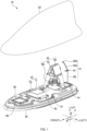
- Fig. 1 is a diagram illustrating a configuration of the vehicular antenna device 10 according to a first embodiment of the present disclosure.
- Fig. 1 is a perspective view of the vehicular antenna device 10 with the case 22 removed in the zenith direction (upward direction).
- the vehicular antenna device 10 is a device to be mounted at the upper surface roof of a vehicle (not illustrated) and includes an antenna base 20, a case 22, antennas 30 to 33, and substrates 40 to 42.
- the front-rear direction of the vehicle in which the vehicular antenna device 10 is mounted is defined as the x direction, the right-left direction perpendicular to the x direction as the y direction, and the vertical direction perpendicular to both the x direction and y direction as the z direction.
- the direction to the front side from the driver's seat of the vehicle is defined as the +x direction, the direction to the left side therefrom as the +y direction, and the zenith direction (upward direction) as the +z direction.
- the front-rear, right-left, and up-down directions of the vehicular antenna device 10 are the same as the front-rear, right-left, and up-down directions of the vehicle.
- the antenna base 20 is a plate-shaped member that serves as the bottom surface of the vehicular antenna device 10.
- the antenna base 20 includes, for example, a resin insulating base and a metal base 21, and the metal base 21 is mounted at the insulating base with a plurality of screws (not illustrated).
- the metal base 21 is a plate-shaped member that functions as a ground for the vehicular antenna device 10 with the vehicular antenna device 10 being attached to the roof (not illustrated) of the vehicle. It is assumed that although the antenna base 20 is configured such that the metal base 21 is directly mounted to the insulating base, the present disclosure is not limited to this.
- the antenna base 20 may be configured only with a metal base or metal plate, or may be mounted with another member such as an insulating base or metal plate.
- the antenna base 20 may include an insulating base and a metal plate, or may include an insulating base, a metal base, and a metal plate. Alternatively, a configuration using a pad for waterproof surrounding a metal base may be used without using an insulating base.
- the metal base 21 is formed as an integral metal base mounted with the substrates 40 to 42, as illustrated in Fig. 1 .
- the metal base mounted with the substrates 40 to 42 may not be an integral metal base.
- the substrates 40 to 42 may be mounted to respective separate metal bases, or the metal base mounted with the substrate 40 and substrate 42 and the metal base mounted with the substrate 41 may be separated.
- the separate (divided) metal bases may be electrically connected with another metal base or another metal plate, and may further be held by a resin insulating base.
- a metal plate may be used instead of a metal base, or a combination of a metal base and a metal plate may be used.
- the case 22 is a member (so-called radome) that covers the antenna base 20 to form an accommodation space to accommodate the antennas 30 to 33 with the antenna base 20.
- the case 22 is made of synthetic resin having electromagnetic wave permeability (e.g., ABS resin), and has a shark fin shape whose height is low in the front and increases toward the rear.
- the case 22 is mounted to the antenna base 20 such that the opening on the lower side of the case 22 is closed by the antenna base 20.
- the outer dimensions of the case 23 of an embodiment of the present disclosure are, for example, such that the length in the front-rear direction is substantially 190 mm to 200 mm, the length in the up-down direction is substantially 60 mm to 65 mm, and the length in the right-left direction is substantially 70 mm to 75 mm.
- a pad which is an elastic member, may be provided between the antenna base 20 and the case 22.
- Each of the antennas 30 and 31 is an antenna supporting radio waves in the V2X frequency band (vertically polarized waves that are linearly polarized waves). Specifically, the antennas 30 and 31 are used in the vehicular antenna device 10 to transmit V2X radio waves (e.g., in the 5.9 GHz band) and to receive V2X radio waves using a spatial diversity system.
- V2X radio waves e.g., in the 5.9 GHz band
- the antenna 30 is installed at the substrate 40 that is mounted to the front portion of the metal base 21. Although the details will be described later, the antenna 30 is mainly located in the front of the vehicular antenna device 10 and communicates with another V2X antenna (not illustrated).
- the antenna 31 is installed at the substrate 41 mounted to the rear portion of the metal base 21.
- the antenna 31 is mainly located in the rear of the vehicular antenna device 10 and communicates with another V2X antenna (not illustrated).
- the antenna 30 is a vertically polarized wave monopole antenna used for V2X communication.
- the antenna 30 is a rod-shaped metal member configured to operate as a grounded monopole antenna, and has a feeding point (not illustrated) provided at one end thereof on the substrate 40 side.
- the antenna 30 can exchange signals with a signal processing circuit (not illustrated) via the feeding point and the substrate 40.
- the length from one end to the other end of the antenna 30 of an embodiment of the present disclosure is one-fourth of one wavelength of the V2X frequency band. It is assumed that one wavelength of the V2X frequency band is ⁇ (substantially 50 mm), and accordingly the length of the antenna 30 is ⁇ /4 (substantially 12.5 mm) . Also, since the antenna 30 is mounted at the front surface of the substrate 40 so as to be substantially vertical thereto, the height of the antenna 30 from the front surface of the substrate 40 is ⁇ /4 (substantially 12.5 mm) as well.
- the length (physical length) and distance of the antenna may be described as a so-called electrical length, such as ⁇ /4, using one wavelength ⁇ of the V2X frequency band.
- the electrical length includes not only a single value, but also values that deviate by substantially a predetermined value (e.g., a value of 1/32 of ⁇ ). This is because the wavelength is not necessarily represented by a divisible integer, and the electrical length varies depending on various factors such as the material of the target object and the environment.
- ⁇ /4 means substantially ⁇ /4.
- a predetermined electrical length e.g., ⁇ /4) may be given ⁇ /4 or substantially ⁇ /4. But even when it is simply given ⁇ /4 without “substantially,” it is recognized as including substantially ⁇ /4.
- the antenna 31 is a vertically polarized wave collinear antenna array used for V2X communication.
- the antenna 31 is a rod-shaped metal member mounted to the substrate 41 and includes a linear portion 60, an annular portion 61, a linear portion 62a, and a bent portion 62b.
- the linear portion 60 has a length of ⁇ /2, and a feeding point (not illustrated) is provided at one end on the substrate 41 side.
- the linear portion 62a is provided on the other end side of the linear portion 60, with the annular portion 61 interposed therebetween.
- the linear portion 62a extends from the annular portion 61 so that the antenna 31 does not come into contact with the case 22.
- the linear portion 62a extends from the annular portion 61 so as to be inclined by a predetermined angle in the +x direction from the vertical direction.
- the bent portion 62b is provided at the tip of the linear portion 62a so as to reliably prevent contact between the antenna 31 and the case 22.
- the linear portion 62a may extend in a vertical direction from the annular portion 61, and the provision of the bent portion 62b is not needed, if the height of the case 22 is high enough to prevent contact between the antenna 31 and the case 22, for example.
- the length of the tip from the end portion of the linear portion 62a on the annular portion 61 side to the bent portion 62b in an embodiment of the present disclosure is ⁇ /2.
- the linear portion 60 having a length of ⁇ /2, and the linear portion 62a having a length of ⁇ /2 and bent portion 62b are provided on respective sides of the annular portion 61.
- the gain of the antenna 31 decreases.
- the annular portion 61 which is formed by winding in a spiral shape for one turn, is provided to adjust the phase of the vertically polarized wave in the linear portion 60 and the phase of the vertically polarized wave in the linear portion 62a and bent portion 62b, so that the gain in the desired frequency band at the antenna 31 increases.
- the antenna 31 with such a configuration can, for example, increase the gain of radio waves in the V2X frequency band.
- the antenna 30 is a rod-shaped monopole antenna and the antenna 31 is a collinear antenna array, but they are not limited to the above.
- the antennas 30 and 31 may be, for example, dipole antennas or patch antennas, as long as they are antennas (including grounded and non-grounded) supporting vertically polarized waves in the desired frequency band.
- the antennas 30 and 31 are V2X-compatible antennas, they may be of other communication standards (e.g., Wi-Fi (registered trademark) or Bluetooth (registered trademark)) .
- the antenna 32 is, for example, a patch antenna to receive radio waves in the 1.5 GHz band for the Global Navigation Satellite System (GNSS).
- GNSS Global Navigation Satellite System
- the antenna 32 of an embodiment of the present disclosure is installed at the substrate 42 mounted to the metal base 21, and includes a dielectric member 70 and a radiation element 71.
- the substrate 42 is provided, in the metal base 21, closer to the substrate 40 between the substrate 40 provided most forward and the substrate 41 provided most rearward.
- the antenna 32 is provided closer to the antenna 30 between the antenna 30 and antenna 31.
- the dielectric member 70 is made of a dielectric material such as ceramic, and is a substantially square plate-shaped or box-shaped member in a plan view of the x-y plane viewed from the +z direction.
- a conductor functioning as a ground conductor film (or ground conductor plate) is formed. Then, the back surface of the dielectric member 70 is mounted to the substrate 42 using, for example, an adhesive (not illustrated).
- a substantially square conductive radiation element 71 having equal vertical and horizontal lengths is formed.
- the "substantially square” also includes a shape in which at least one or more of the corners thereof are cut off obliquely with respect to the sides thereof, and a shape in which any of the sides is provided with a cutout (recessed portion) or protrusion (protruding portion).
- the shape of the dielectric member 70 is not limited to a substantially square shape, and may be a quadrilateral shape such as a substantially rectangular shape, or a shape such as a substantially circular shape or a substantially elliptical shape.
- the radiation element 71 is provided with two feeding points (not illustrated).
- two feed lines are respectively connected to the two feeding points through two through-holes (not illustrated) that penetrate the substrate 42 and the dielectric member 70. By distributing power with a phase difference to these feed lines, they operate as circularly polarized antennas.
- the antenna 32 is a GNSS antenna, it may also be an antenna to receive radio waves of other standards, such as Satellite Digital Audio Radio Service (SDARS).
- SDARS Satellite Digital Audio Radio Service
- the antenna 33 is an antenna to receive radio waves in the DAB (Digital Audio Broadcast) waveband, for example. Specifically, the antenna 33 receives, for example, radio waves in Band-III (174 MHz to 240 MHz).
- the antenna 33 includes a holder 80, a helical element (hereinafter simply referred to as "coil") 81 and a capacitively loaded element 82.
- the antenna 33 receives radio waves in Band-III (174 MHz to 240 MHz), but the band may be, for example, another band of the DAB (Digital Audio Broadcast) waveband, such as L-Band (1452 MHz to 1492 MHz).
- the holder 80 is a resin member to hold the coil 81 and the capacitively loaded element 82 and is mounted to the metal base 21.
- the coil 81 is mounted to the cylindrical portion of the holder 80.
- the coil 81 has one end configured to be electrically connected to a circuit board (not illustrated) provided at the metal base 21, and the coil 81 has the other end configured to be electrically connected to the capacitively loaded element 82.
- the capacitively loaded element 82 is an element configured to resonate in the desired frequency band with the coil 81, and is a metal body having two quadrilateral bodies respectively attached, at the lower parts thereof, to the left and right sides of the upper part of the holder 80.
- Fig. 1 for convenience, only the metal body on the right side of the upper part of holder 80 is illustrated, but there is also a metal body as with the metal body on the right side attached to the left side of holder 80.
- the capacitively loaded element 82 includes a lower metal body (not illustrated) connecting the left and right metal bodies.
- the "metal body” refers to an object formed by processing a metal member, including, for example, a three-dimensional metal member other than non-plate-shaped member, in addition to a plate-shaped metal member such as a metal plate.
- the right-side metal body and the left-side metal body may be connected at the apex portion, or integrally formed, and may have three-dimensional shapes such as an inverted V-shape, inverted U-shape, mountain-like shape, or a shape obtained by excluding the bottom edge of a trapezoid, when viewed from the front or rear.
- the holder 80 is installed such that the distance between the rear end portion of the capacitively loaded element 82 and the tip of the bent portion 62b in the antenna 31 is, for example, shorter than the one wavelength ⁇ of the V2X frequency band.
- the length of the side in the rear of the capacitively loaded element 82 is, for example, ⁇ /2, but it may be designed slightly longer than ⁇ /2. In such a case, the capacitively loaded element 82 will operate as a reflector for the antenna 31, which enables the improvement of the gain of the antenna 31.
- the antenna 33 is used as a reflector, the antenna 33 is provided closer to the antenna 31 between the antenna 30 and antenna 31.
- the V2X antennas 30 and 31, the GNSS antenna 32, and the DAB antenna 33 as described above are provided.
- the V2X antennas 30 and 31 have the highest operating frequency band of 5 GHz band and a shortest wavelength ⁇ of substantially 50 mm.
- the case 22 may affect the directivity of the antennas 30 and 31.
- a model simulating the vehicular antenna device 10 is used to verify the influence of the case on the directivity of the antenna.
- the relationship between the position of the antenna of the vehicular antenna device and the case is verified.
- Fig. 2A is a diagram illustrating an example of a case 300 and a ground plate 320.
- Fig. 2B is a diagram for explaining the position of an antenna 310.
- Fig. 2B is a cross sectional view of the case 300 taken along line A-A of Fig. 2A such that the antenna 310 inside the case 300 can be seen.
- the longitudinal axis (the axis on the major diameter) passing through the geometric center of the elliptical bottom surface of the case 300 is depicted by a dotted line.
- the case 300 includes an elliptical top surface 300a when viewed in a plan view of the x-y plane from the +z direction, and a cylindrical member 300b extending, in the -z direction (downward direction), from the outer periphery of the top surface 300a.
- the cylindrical member 300b is formed such that when the case 300 is installed at the ground plate 320 placed on the x-y plane, the ground plate 320 and the top surface 300a are parallel, and the angle formed by the ground plate 320 and the cylindrical member 300b is 90°.
- the major diameter of the top surface 300a is 220 mm, and the minor diameter is 110 mm.
- the height of the cylindrical member 300b (the distance from the ground plate 320 to the top surface 300a) is 55 mm.
- the antenna 310 is a monopole antenna capable of supporting vertically polarized waves in the V2X frequency band. Since the antenna 310 is grounded to the ground plate 320, the length of the antenna 310 is ⁇ /4 (substantially 12.5 mm). In addition, in an embodiment of the present disclosure, the distance from the inside of the cylindrical member 300b on the +x-side to the antenna 310, along the longitudinal axis (axis on the major diameter), as depicted by the dotted line in Fig. 2B , passing through the center (geometric center) of the top surface 300a, is referred to as distance Da.
- Figs. 3 and 4 are calculation results illustrating how the gain (dBi) in the horizontal plane of vertical variation of the antenna 310 varies in all directions.
- an azimuth angle of 0° corresponds to the +x direction (forward direction)
- an azimuth angle of 90° corresponds to the +y direction (left direction).
- the range of ⁇ (hereinafter referred to as "range of predetermined angles”) is based on an azimuth angle of 0°, and includes the range up to ⁇ ° counterclockwise (+ direction) and the range up to ⁇ ° clockwise (- direction).
- the "gain deviation” refers to the difference between the maximum gain and the minimum gain within the range of predetermined angles.
- the distance Da exceeds 82 mm, it fluctuates greatly within a range of substantially 20 dBi to 40 dBi.
- the antennas 30 and 31 receive vertically polarized waves by a so-called diversity system.
- the preferable distance of 75 mm for reducing gain deviation corresponds to three-halves of one wavelength ⁇ of the V2X frequency band ((3 ⁇ ⁇ )/2), and 50 mm corresponds to one wavelength ⁇ .
- the shape of the end portion on the +x-side of the case 300 illustrated in Figs. 2A and 2B is similar to the shape on the rear side (-x-side) of the shark-fin-type case 22 of Fig. 1 , for example.
- a case having a shape on the front side (+x-side) similar to that of the shark-fin-type case 22 is used, to carry out the same verification as in Fig. 2 .
- Fig. 6A is a diagram illustrating an example of a case 400 and a ground plate 420.
- Fig. 6B is a diagram for explaining the position of an antenna 410.
- Fig. 6B is a cross sectional view of the case 400 taken along line A-A of Fig. 6A such that the antenna 410 inside the case 400 can be seen.
- the longitudinal axis (the axis on the major diameter) passing through the geometric center of the elliptical bottom surface of the case 400 is depicted by a dotted line.
- the case 400 includes an elliptical top surface 400a when viewed in a plan view of the x-y plane from the +z direction, and a cylindrical member 400b extending, in the -z direction (downward direction), from the outer periphery of the top surface 400a.
- the cylindrical member 400b is formed such that when the case 400 is installed at a ground plate 420 placed on the x-y plane, the height of the accommodation space in the front portion of the case 400 gradually increases, and the ground plate 420 and the top surface 400a are parallel.
- the cylindrical member 400b is formed such that the angle formed between a straight line from the foremost portion (the portion in the most +x direction) of the case 400 on the ground plate 420 to the top surface 400a and the ground plate 420 is angle ⁇ (e.g., 40°). Furthermore, the cylindrical member 400b is formed such that the angle formed between a straight line from the rearmost portion (the portion in the most -x direction) of the case 400 on the ground plate 420 to the top surface 400a and the ground plate 420 is 90°.
- angle ⁇ e.g. 40°
- the top surface 400a has a major diameter of 161 mm and a minor diameter of 20 mm. Further, the height of the cylindrical member 400b (the distance from the ground plate 420 to the top surface 400a) is 55 mm. Further, the major diameter and minor diameter of the elliptical bottom surface of the case 400 are 220 mm and 45 mm, respectively.
- the antenna 410 is a monopole antenna capable of supporting vertically polarized waves in the V2X frequency band, similar to the antenna 310 illustrated in Fig. 2 . Thus, detailed description is omitted here.
- the distance from the inner tip portion of the cylindrical member 400b on the +x-side to the antenna 410 in the longitudinal axis passing through the geometric center of the elliptical bottom surface of the case 400 is referred to as a distance Db.
- the height of the case 400 gradually increases from the tip portion toward the rear until it reaches a predetermined height (55 mm), but the antenna 410 cannot be installed on the front portion of the case 400 where the height of the case 400 is lower than the height of the antenna 410.
- the length of the antenna 410 is ⁇ /4 (substantially 12.5 mm), and the angle ⁇ is 40°.
- the antenna 410 needs to be arranged at least the distance Db of substantially 14 mm or more apart therefrom.
- Fig. 7 is a chart illustrating the relationship between distance Db and gain deviation.
- ⁇ ⁇ 45°, ⁇ 60°, ⁇ 90°, and ⁇ 120°
- the smaller the distance Db the smaller the gain deviation tends to be, and in particular, when the distance Db is 80 mm or greater, the gain deviation tends to gradually increase.
- the distance Db in order to suppress increase in the gain deviation while the antenna 410 is arranged inside the case 400, it is preferable to set the distance Db to 90 mm (reference position + 76 mm) or less.
- Setting the distance Db to 90 mm or less, or 64 mm or less, is equivalent to setting the distance to 76 mm or less, or 50 mm or less, from the reference position, at which the antenna contacts the case. These distances are substantially the same as the preferred distances (75 mm or 50 mm) with respect to the distance Da in the case of Fig. 2 . Accordingly, in either case of Fig.
- the directivity can be improved by providing the contact portion of the antenna with the case at a distance of substantially 75 mm (three-halves of one wavelength: (3 ⁇ ⁇ )/2) or less, or more preferably, substantially 50 mm (one wavelength: ⁇ ) or less, from the position at which the antenna contacts the case.
- a portion of the antenna to be in contact with the case is placed at a "desired position," which is a position separated by a distance of, for example, equal to or less than three-halves of the V2X wavelength (3 ⁇ /2) in the horizontal direction.
- the "portion of the antenna to be in contact with the case” refers to the portion that would virtually come into contact with the case when the antenna is moved in the horizontal direction from its actual installation position.
- Fig. 8 is a diagram for explaining the position of the front antenna 30 in the vehicular antenna device 10.
- Fig. 8 is a cross sectional view of the case 22 taken along a line along the x-axis direction passing through the center point of the case 22 in the right-left direction.
- the position of the antenna 30 is determined such that a portion of the antenna 30 is at the desired position described above.
- the antenna 30 (tip portion P1) is provided at a position separated rearward by a distance D1 from the position at which the tip portion P1 of the antenna 30 contacts the case 22.
- the distance D1 is a distance (e.g., 5 mm) shorter than substantially 75 mm, which is three-halves of the V2X wavelength (3 ⁇ /2).
- the antenna 30 should be placed close to the case 22, but if it is brought into contact therewith, a load is applied to the antenna 30 due to the vibration of the vehicle, and thus it is separated slightly therefrom.
- the state in which the tip portion P1 of the antenna 30 is in contact with the case 22 is indicated by a dotted line for convenience, but this is a virtual state.
- Fig. 9 is a diagram for explaining the position of the rear antenna 31 in the vehicular antenna device 10.
- Fig. 9 is also a cross sectional view of the case 22 in the same manner as in Fig. 8 .
- the position of the antenna 31 is determined such that a portion of the antenna 31 is at the desired position described above.
- the antenna 31 (end portion P2) is provided at a position separated forward by a distance D2 from the position at which the end portion P2 of the linear portion 60 on the annular portion 61 side in the antenna 31 contacts the case 22.
- the distance D2 is a distance (e.g., 5 mm) shorter than substantially 75 mm, which is three-halves of the V2X wavelength (3 ⁇ /2).
- the antenna 31 should be placed close to the case 22, but if brought into contact therewith, a load is applied to the antenna 31 due to the vibration of the vehicle, and thus it is separated slightly therefrom.
- the dotted line indicates a virtual state in which the end portion P2 of the linear portion 60 is in contact with the case 22.
- Fig. 10 is a diagram illustrating the horizontal directivity of the antennas 30 and 31 installed in the vehicular antenna device 10.
- the solid line indicates the directivity of the antenna 30 and the dotted line indicates the directivity of the antenna 31.
- an azimuth angle of 0° corresponds to the +x direction (forward direction)
- an azimuth angle of 90° corresponds to the +y direction (left direction).
- Fig. 10 provides simulation results illustrating the horizontal directivity of the antennas 30 and 31 when an infinite ground plate is used.
- the vehicular antenna device 10 can achieve a gain that is slightly smaller than 10 dBi with respect to vertically polarized waves in the V2X frequency band in the front, rear, right, and left directions on the infinite ground plate. As such, when the antennas 30 and 31 are used, good directivity can be obtained in the horizontal plane.
- the vehicular antenna device 10 illustrated in Fig. 1 is a so-called composite antenna device, and includes the GNSS antenna 32 and the DAB antenna 33 in addition to the V2X antennas 30 and 31.
- individual antennas needs to be arranged so that unnecessary electrical interference does not occur among the antennas.
- the GNSS antenna 32 and the DAB antenna 33 can be arranged in the long interval between the antenna 30 and antenna 31.
- the antennas 30 and 31 carry out at least one of receiving or transmitting signals in the same frequency band.
- antennas here, antennas 32 and 33
- antennas of frequency bands lower than the frequency bands supported by the antennas 30 and 31 are arranged between the antenna 30 and antenna 31.
- Antennas supporting higher frequency bands are more likely to be affected by the case 22, and in contrast, antennas supporting lower frequency bands are less likely to be affected by the case 22.
- the antennas 30 and 31 are arranged on the outer side of the vehicular antenna device 10, and the antennas 32 and 33 are arranged on the inner side of the vehicular antenna device 10.
- the height of the antenna 30 is lower than the height of the antenna 31. Accordingly, in the vehicular antenna device 10, by setting the antenna system of the antennas 30 and 31 according to the front and rear positions at which the antennas are to be arranged, and to the space inside the case 22, it is possible to reduce the size of the vehicular antenna device 10 while securing the directivity and gain of the antennas 30 and 31.
- the antennas 30 and 31, which support the same frequency band have different antenna systems.
- the antennas 30 and 31 are not limited to the case of different antenna systems, and may be of the same antenna system depending on design requirements.
- the vehicular antenna device 10 has a plurality of antennas arranged therein, they may be a combination of antennas of the same antenna system, or may be antennas of antenna systems that are all different.
- the antennas 30 and 31 are arranged substantially in the center of the vehicular antenna device 10 in the width direction (Y direction).
- the directivity of the antennas 30 and 31 can be symmetrical with respect to the X-axis, which facilitates adjustment and control so as to provide directivity in the front-rear direction (X direction).
- the antenna 32 is arranged such that the height of the top surface is lower than the top end of the antenna 30. In this case, the electrical properties of the antenna 30 are improved.
- the antenna 32 may be arranged so that the height of the top surface is higher than the top end of the antenna 30. In this case, the electrical properties of the antenna 32 are improved. That is, in an embodiment of the present disclosure, the height of the antennas arranged in the vehicular antenna device 10 can be selected depending on the application of design. This makes it possible to ensure the characteristics of the antennas arranged in the vehicular antenna device 10 without impairing the design of the vehicular antenna device 10, and achieve miniaturization as well.
- the antennas 30, 31, and 32 are installed at different substrates, respectively. However, at least two or more of the antennas 30, 31, and 32 may be installed at the same substrate. This makes it possible to improve ease of assembly of the antenna.
- the antenna 30 corresponds to a "first antenna” and the antenna 31 corresponds to a "second antenna.” Further, for example, the antenna 32 corresponds to a "third antenna.”
- the tip portion P1 of the antenna 30 corresponds to "at least a portion of the first antenna,” and the distance D1 corresponds to a "predetermined distance.”
- the +x direction corresponds to a "first direction”
- the -x direction corresponds to a "second direction opposite to the first direction.”
- the end portion P2 of the linear portion 60 of the antenna 31 corresponds to "at least a portion of the second antenna,” and the distance D2 corresponds to a "predetermined distance.”
- the position separated by the distance D1 i.e., the position of the tip portion P1 of the installed antenna 30
- the position separated by the distance D2 i.e., the position of the end portion P2 of the installed antenna 31
- the position separated by the distance D2 i.e., the position of the end portion P2 of the installed antenna 31
- the position separated by the distance D2 i.e., the position of the end portion P2 of the installed antenna 31
- Fig. 11 is a diagram for explaining the configuration of the vehicular antenna device 11 of a second embodiment.
- Fig. 11 depicts a state in which the case 22 is removed in the zenith direction (upward direction).
- the vehicular antenna device 11 includes an antenna 34 and parasitic elements 35 and 36a to 36c, instead of the antenna 30 of the vehicular antenna device 10 of Fig. 1 .
- the antenna 34 and the parasitic elements 35 and 36a to 36c will be described here.
- the three parasitic elements 36a to 36c may be hereinafter collectively referred to as a parasitic element 36.
- the antenna 34 is a vertically polarized wave monopole antenna used for V2X communication, similarly to the antenna 30.
- the antenna 34 is a rod-shaped metal member configured to operate as a grounded monopole antenna, and has a feeding point (not illustrated) provided at one end thereof on the substrate 40 side.
- the antenna 30 can exchange signals with a signal processing circuit (not illustrated) via the feeding point and the substrate 40.
- the length from one end to the other end of the antenna 34 of an embodiment of the present disclosure is a half of one wavelength of the V2X frequency band. Accordingly, the length of the antenna 34 is ⁇ /2 (substantially 25 mm). Further, since the antenna 34 is mounted at the front surface of the substrate 40 so as to be substantially vertical thereto, the height of the antenna 34 from the front surface of the substrate 40 is also ⁇ /2 (substantially 25 mm).
- the position of the antenna 34 is determined such that a portion of the antenna 34 is at the desired position described above.
- the antenna 34 (tip portion P3) is provided at a position separated rearward by a distance D3 from the position at which the tip portion P3 of the antenna 34 contacts the case 22.
- the distance D3 is a distance (e.g., 5 mm) shorter than substantially 75 mm, which is three-halves of the V2X wavelength (3 ⁇ /2).
- the parasitic elements 35 and 36 are elements to improve directivity while increasing the gain in front (+x direction) of the antenna 34.
- the parasitic element 35 is a rod-shaped metal body that functions as a so-called director with respect to the antenna 34 and is installed on the front side relative to the antenna 34. Further, the parasitic element 35 is installed at the substrate 40 in a non-grounded state.
- the length of the parasitic element 35 is equal to or less than the length of the antenna 34 ( ⁇ /2).
- Each of the parasitic elements 36a to 36c is a rod-shaped metal body that functions as a so-called reflector with respect to the antenna 34 and is installed on the rear side relative to the antenna 34.
- the parasitic elements 36a to 36c are provided between the antenna 30 and the antenna 32.
- the parasitic elements 36a to 36c are installed at the metal base 21 in a non-grounded state.
- the length of each of the parasitic elements 36a to 36c is equal to or longer than the length of the antenna 34 (substantially ⁇ /2).
- each of the parasitic elements 36a to 36c in an embodiment of the present disclosure is bent, to thereby prevent the parasitic elements 36a to 36c from contacting the case 22. Accordingly, for example, when the accommodation space of the case 22 is sufficiently high, the parasitic elements 36a to 36c may be linear members.
- an aspect in which the parasitic elements 36a to 36c are bent may be different from that illustrated in Fig. 11 .
- the tips of the parasitic elements 36a and 36c are bent in the -x direction (rearward direction), and the tip of the parasitic element 36b is bent in the +x direction (forward direction).
- the parasitic elements 36 that are bent in different directions coexist.
- all of the parasitic elements 36a to 36c may be bent in the same direction.
- each of the parasitic elements 36a to 36c is bent at one position of the tip portion (upper portion) .
- each of the parasitic elements 36a to 36c may be bent at a lower portion, or may be bent at a plurality of positions.
- the angle at which each of the parasitic elements 36a to 36c is bent may not be 90° as illustrated in Fig. 11 , but may be an angle at which the tips thereof are away from the case 22, for example. This can further prevent the parasitic elements 36a to 36c from coming into contact with the case 22, and further miniaturize the vehicular antenna device 11.
- the parasitic elements 35 and 36 are installed within a range of a virtual circle having a radius of ⁇ /2 (hereinafter referred to as the "circle C") with the position at which the antenna 34 is installed as the center thereof, so as to improve the forward gain of the antenna 34.
- the parasitic element 35 is installed within the range of the half of the circle C on the +x side
- the parasitic element 36 is installed within the range of the half of the circle C on the -x side.
- both the parasitic elements 35 and 36 are provided in the vehicular antenna device 11, only one of them may be provided. Further, although three parasitic elements 36 operating as reflectors are provided, at least one parasitic element 36 may be provided.
- the length of the parasitic element 35 is ⁇ /4 or less
- the length of the parasitic element 36 is ⁇ /4 or more.
- the length of each of the parasitic elements 35 and 36 only has to be set such that they can appropriately operate as a director and a reflector with respect to the antenna 34.
- Fig. 13 is a diagram illustrating simulation results of the horizontal directivity of the antennas 31 and 34 installed in the vehicular antenna device 11 at the infinite ground plate.
- the solid line indicates the directivity of the antenna 34 and the dotted line indicates the directivity of the antenna 31.
- an azimuth angle of 0° corresponds to the +x direction (forward direction)
- an azimuth angle of 90° corresponds to the +y direction (left direction).
- the antenna 34 has improved gain in the forward direction and right-left direction as compared to the antenna 30. Accordingly, when using the antennas 31 and 34, very good directivity can be obtained in the horizontal plane.
- the directivity of the antenna 31 in both Figs. 10 and 13 is substantially the same.
- the vehicular antenna device 11 includes the parasitic element 35 configured to operate as a director and the parasitic element 36 configured to operate as a reflector. Accordingly, in the vehicular antenna device 11, the gain in front of the antenna 34 (+x direction) particularly increases, and the directivity is also improved.
- Fig. 14 is a diagram illustrating the gain in the horizontal plane of the antenna 34 in each of the vehicular antenna device 11 and the vehicular antenna device X (described later).
- Fig. 15 is a diagram illustrating the gain in the horizontal plane of the antenna 31 in each of the vehicular antenna device 11 and the vehicular antenna device X.
- the "vehicular antenna device X" is a device to be compared having a configuration obtained by excluding the GNSS antenna 32 and the DAB antenna 33 from the configuration of the vehicular antenna device 11 of Fig. 11 .
- the difference between the vehicular antenna device 11 and the vehicular antenna device X is only the GNSS antenna 32 and DAB antenna 33, and thus the vehicular antenna device X is not illustrated here for convenience.
- the antenna 31 mainly supports vertically polarized waves in the -x direction (within a range of ⁇ 120°around an azimuth angle of 180°). Thus, even if the gain in the range of azimuth angles of 30° to 330° in the gain of the antenna 31 decreases, the characteristics of the antenna 31 are not affected.
- each of the antennas 31 and 34 being arranged at a position close to the case 22, it is possible to obtain good directivity while preventing the antennas 31 and 34 from being affected by other antennas.
- the antennas 34 and 31 carry out at least one of receiving or transmitting signals in the same frequency band. Moreover, between the antenna 34 and antenna 31, antennas (here, antennas 32 and 33) of frequency bands lower than the frequency bands supported by the antennas 34 and 31 are arranged. Antennas supporting higher frequency bands are more likely to be affected by the case 22, and conversely, antennas supporting lower frequency bands are less likely to be affected by the case 22. Thus, in an embodiment of the present disclosure, the antennas 34 and 31 are arranged on the outer side of the vehicular antenna device 11, and the antennas 32 and 33 are arranged on the inner side of the vehicular antenna device 11. By arranging the antennas as such, it is possible to improve the performance of each antenna.
- the height of the antenna 34 is lower than the height of the antenna 31. Accordingly, in the vehicular antenna device 11, by setting the antenna system of the antennas 34 and 31 according to the front and rear positions at which the antennas are to be arranged, and to the space inside the case 22, it is possible to reduce the size of the vehicular antenna device 11 while securing the directivity and gain of the antennas 34 and 31.
- the antennas 34 and 31, which support the same frequency band have different antenna systems, respectively.
- the antennas 34 and 31 are not limited to the case of having different antenna systems, and may have the same antenna system depending on design requirements.
- the vehicular antenna device 11 when the vehicular antenna device 11 includes a plurality of antennas arranged, it may include a combination of antennas having the same antenna system, or may include antennas having antenna systems that are all different.
- the antennas 34 and 31 are arranged substantially in the center of the vehicular antenna device 11 in the width direction (Y direction).
- the directivity of the antennas 34 and 31 can be symmetrical with respect to the X-axis, and adjustment and control so as to provide directivity in the front-rear direction (X direction) is facilitated.
- the antenna 32 is arranged such that the height of the top surface thereof is lower than the top end of the antenna 34. In this case, the electrical properties of the antenna 34 are improved.
- the antenna 32 may be arranged such that the height of the top surface is higher than the top end of the antenna 34. In this case, the electrical properties of the antenna 32 are improved. That is, in an embodiment of the present disclosure, the height of the antennas arranged in the vehicular antenna device 11 can be selected depending on the application of design. This can ensure the characteristics of the antennas arranged in the vehicular antenna device 11 without impairing the design of the vehicular antenna device 11, and achieve miniaturization as well.
- the antennas 34, 31, and 32 are installed at different substrates, respectively. However, at least two or more of the antennas 34, 31, and 32 may be installed at the same substrate. This makes it possible to improve ease of assembly of the antenna.
- the antenna 34 corresponds to the "first antenna.” Further, for example, the corner portion P3 of the antenna 34 corresponds to "at least a portion of the first antenna,” and the distance D3 corresponds to the "predetermined distance.”
- the position separated by the distance D3 i.e., the position of the corner portion P3 of the installed antenna 34 from the position at which the corner portion P3 of the antenna 34 contacts the case 22 corresponds to the "first position.”
- Fig. 16 is a diagram for explaining the configuration of the vehicular antenna device 12 of a third embodiment.
- an antenna 37 is provided instead of the antenna 30 in the vehicular antenna device 10 of Fig. 1 .
- the configuration other than the antenna 37 is the same as that of the vehicular antenna device 10, and thus the antenna 37 will be described here.
- the antenna 37 is a patch antenna supporting vertically polarized waves in the V2X frequency band, and includes a patch element 37a and a ground conductor plate 37b.
- the patch element 37a is a member formed by bending a metal plate to have a shape protruding in the +x direction.
- the patch element 37a has an apex portion 38 on the +x side with a predetermined width (length in the y-axis direction), and two inclined portions 39, obtained by bending, toward the -x direction, at the sides of the apex portion 38 on the right and left thereof, respectively.
- the distance L from each of the sides of the apex portion 38 on the right and left thereof to the sides at the ends of the inclined portions 39 that are parallel to the sides of the apex portion 38 on the right and left thereof is, for example, 12 mm.
- the patch element 37a is provided with a feeding point (not illustrated) .
- the ground conductor plate 37b is a member formed by bending a metal plate to have a shape protruding in the +x direction. Further, the ground conductor plate 37b of an embodiment of the present disclosure is electrically connected to the metal base 21 so as to function as a ground.
- a synthetic resin dielectric (not illustrated) is sandwiched between the patch element 37a and the ground conductor plate 37b so as to fill the gap therebetween. Further, the dielectric adheres to each of the patch element 37a and the ground conductor plate 37b with an insulating tape (not illustrated). Thus, the patch element 37a is fixed to the ground conductor plate 37b via the dielectric. Even when such an antenna 37 is used, it is possible to receive vertically polarized waves in the V2X frequency band.
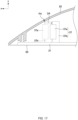
- Fig. 17 is a diagram for explaining the position of the front antenna 37 in the vehicular antenna device 12.
- Fig. 17 also is a cross sectional view of the case 22 in the same manner as in Fig. 8 described above.
- the position of the antenna 37 is determined such that a portion of the antenna 37 is at the desired position described above.
- the antenna 37 (corner portion P4) is provided at a position separated rearward by a distance D4 from the position at which the corner portion P4 above the ground conductor plate 37b of the antenna 37 contacts the case 22.
- the distance D4 is a distance (e.g., 5 mm) shorter than substantially 75 mm, which is three-halves of the V2X wavelength (3 ⁇ /2).
- the dotted line indicates a virtual state in which the corner portion P3 of the ground conductor plate 37b of the antenna 37 is in contact with the case 22.
- the vehicular antenna device 12 can obtain good directivity (in particular, forward directivity) in the V2X frequency band.
- the antenna 37 corresponds to the "first antenna.” Further, for example, the corner portion P4 of the antenna 37 corresponds to "at least a portion of the first antenna,” and the distance D4 corresponds to the "predetermined distance.”
- the position separated by the distance D4 i.e., the position of the corner portion P4 of the installed antenna 37 from the position at which the corner portion P4 of the antenna 37 contacts the case 22 corresponds to the "first position.”
- Fig. 18 is a diagram for explaining the configuration of the vehicular antenna device 13 of a fourth embodiment.
- the vehicular antenna device 13 is housed, for example, in a cavity between a roof panel (not illustrated) of the vehicle and a roof lining in the ceiling surface of the vehicle interior.
- the vehicular antenna device 13 is a compound antenna device including a plurality of antennas operating in different frequency bands, and includes a metal base 500, a case 501, and antennas 510 to 514.
- the antenna 512 is a collective term for the antennas 512a to 512d
- the antenna 513 is a collective term for the antennas 513a and 513b
- the antenna 514 is a collective term for the antennas 514a and 514b.
- the metal base 500 is a substantially quadrilateral metal plate used as a ground common to the antennas 510 to 514, and is installed on the roof lining of the vehicle. Further, the metal base 500 is a thin plate extending over the front, rear, right, and left directions.
- the case 501 is a box-shaped member, and one face on the lower side of its six faces is open. Further, since the case 501 is made of an insulating resin, radio waves can pass through the case 501. Then, the case 501 is mounted to the metal base 500 such that the opening on the lower side of the case 501 will be closed by the metal base 500. Thus, the antennas 510 to 514 are accommodated in the space (accommodation space) inside the case 501.
- the antenna 510 is, for example, a patch antenna compatible with the SDARS system, and receives left-hand circularly polarized waves in the 2.3 GHz band.
- the antenna 510 is installed near the center of metal base 500.
- the antenna 511 is, for example, a planar antenna compatible with GNSS, and receives radio waves in the 1.5 GHz band from an artificial satellite.
- the antenna 511 is installed in the rear (-x direction) of the antenna 510.
- the antenna 512 is an antenna supporting vertically polarized waves in the V2X frequency band, and is similar to the antenna 30 of the vehicular antenna device 10 of Fig. 1 .
- Each of the antennas 512a to 512d is arranged around the antenna 510.
- the antennas 512a and 512b are respectively arranged on the front and rear sides of the antenna 510.
- the antennas 512c and 512d are respectively arranged on the left and right sides of the antenna 510.
- the antenna 512a mainly supports vertically polarized waves from the front (+x direction), and the antenna 512b mainly supports vertically polarized waves from the rear (-x direction). Further, the antenna 512c mainly supports vertically polarized waves from the left side (+y direction), and the antenna 512d mainly supports vertically polarized waves from the right side (-y direction).
- the vehicular antenna device 13 includes a plurality of antennas 512a to 512d with different directivities, thereby being able to receive desired radio waves using a diversity system. Details of the installation positions of the antennas 510a to 510d will be described later.
- the antennas 513a and 513b are, for example, telematics antennas compatible with the fifth-generation mobile communication system.
- the antennas 513a and 513b transmit and receive radio waves in the Sub-6 band defined by the standards of the fifth-generation mobile communication system.
- the antennas 514a and 514b are, for example, telematics antennas compatible with Long Term Evolution (LTE) and fifth-generation mobile communication systems.
- the antenna 514 transmits and receives radio waves in the 700 MHz to 2.7 GHz frequency band defined by the LTE standards. Further, the antenna 514 also transmits and receives radio waves in the Sub-6 band defined by the standards of the fifth-generation mobile communication system, that is, frequency bands from 3.6 GHz to less than 6 GHz.
- the communication standards and frequency bands applicable to the antennas 510 to 514 are not limited to those described above, and other communication standards and frequency bands may be used.
- Fig. 19 is a diagram for explaining the installation position of the antenna 512a. Specifically, Fig. 19 is an enlarged diagram of the vicinity of the installation position of the antenna 512a in the cross section of the vehicular antenna device 13 taken along line A-A of Fig. 18 .
- the position of the antenna 512a is determined such that a portion of the antenna 512a is at the desired position described above.
- the rod-shaped antenna 512a (tip portion P5) is provided at a position separated rearward by a distance D5 from the position at which the tip portion P5 of the antenna 512a contacts the case 501.
- the distance D5 is a distance (e.g., 5 mm) shorter than substantially 75 mm, which is three-halves of the V2X wavelength (3 ⁇ /2).
- the dotted line indicates a virtual state in which the tip portion P5 of the antenna 512a is in contact with the case 501.
- the vehicular antenna device 13 can improve the directivity in the four directions of front, rear, right, and left in the V2X frequency band.
- the vehicular antenna device 13 in Fig. 18 includes four V2X antennas 512a to 512d, but is not limited to this.
- V2X antennas only two antennas 512a and 512b in the front-rear direction may be provided, or only two antennas 512c and 512d in the right-left direction may be provided. Even in such cases, the directivity of the provided antennas can be improved.
- the antenna 512a corresponds to the "first antenna” and the antenna 512b corresponds to the "second antenna.” Further, for example, the antenna 510 corresponds to the "third antenna.”
- the tip portion P4 of the antenna 512a corresponds to "at least a portion of the first antenna,” and the distance D4 corresponds to the "predetermined distance.”
- the +x direction corresponds to the "first direction”
- the -x direction corresponds to the "second direction opposite to the first direction.”
- the position separated by the distance D4 i.e., the position of the tip portion P4 of the installed antenna 512a
- the position at which the tip portion P4 of the antenna 512a contacts the case 501 corresponds to the "first position.”
- the position corresponding to the tip portion of the antenna 512b corresponds to the "second position.”
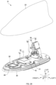
- Fig. 20 is a diagram illustrating the configuration of the vehicular antenna device 14 as a fifth embodiment of the present disclosure.
- the vehicular antenna device 14 relates to the antenna supporting radio waves in the V2X frequency band, and includes only the antenna 30.
- the vehicular antenna device 14 excludes the antenna 31 or substrate 41, as opposed to the vehicular antenna device 10 of the first embodiment.
- the vehicular antenna device 14 has the same configuration as the vehicular antenna device 10, except that it excludes the antenna 31 or substrate 41.
- the same components as of the vehicular antenna device 10 are given the same reference numerals as of the vehicular antenna device 10.
- Fig. 20 is a perspective view of the vehicular antenna device 14 with the case 22 removed in the zenith direction (upward direction), as in Fig. 1 .
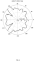
- Fig. 21 is a diagram illustrating the horizontal directivity of the antenna 30 installed at the vehicular antenna device 14. Further, as described above, an azimuth angle of 0° corresponds to the +x direction (forward direction), and an azimuth angle of 90° corresponds to the +y direction (left direction). Fig. 21 provides simulation results indicating the horizontal directivity of the antenna 30 when an infinite ground plate is used. As illustrated in Fig. 21 , in an embodiment of the present disclosure, the vehicular antenna device 10 can achieve a gain slightly smaller than 10 dBi with respect to vertically polarized waves in the V2X frequency band over the front, rear, right, and left directions on the infinite ground plate, although there are some exceptions. As such, when the antenna 30 is used, good directivity can be obtained in the horizontal plane.
- the vehicular antenna device 14 relates to the antenna supporting to radio waves in the V2X frequency band, and includes only the front antenna 30.
- the vehicular antenna device may relate to the antenna supporting to radio waves in the V2X frequency band, and include only the rear antenna 31. Even in this case, by setting the position of the antenna 31 at a desired position, it is possible to reduce the gain deviation in a wide angular range, thereby being able to improve the directivity.
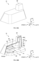
- Figs. 22A and 22B are each a perspective view illustrating the periphery of the substrate 41 of the vehicular antenna device 10.
- Fig. 22A is a perspective view in which the substrate 41 and the like are mounted to the metal base 21, and Fig. 22B illustrates an exploded perspective view in which the substrate 41 and the like are removed from the metal base 21.
- Fig. 23 is a plan view illustrating the periphery of the substrate 41 of the vehicular antenna device 10.
- the antenna 31 of the vehicular antenna device 10 described above is installed at the substrate 41 mounted to the rear portion of the metal base 21.
- the antenna 31 is electrically connected to the substrate 41 at a feeder (not illustrated) .
- the antenna 31 is connected to the coaxial cable 44 illustrated in Fig. 22B through a matching circuit (not illustrated) implemented at the substrate 41.
- the substrate 41 may be implemented with a circuit element (s) and/or an electronic component(s) other than the matching circuit.
- the outer periphery of the substrate 41 on the matching circuit side (lower side) is electrically connected to the ground on the antenna 31 side via a through hole(s), a via-hole(s), and/or the like.
- the outer periphery of the substrate 41 on the matching circuit side is subjected to conductive surface treatment such as solder leveling or gold plating.
- a receiving portion 49 and a cable accommodating portion 51 are formed, as illustrated in Figs. 22A to 23 .
- the receiving portion 49 is, as illustrated in Fig. 22B , a receiving structure (recessed portion) to receive the substrate 41, formed to contact the outer periphery of the substrate 41 on the matching circuit side (lower side).
- the substrate 41 is assembled to the metal base 21 using screws 43, so that the substrate 41 is held while a pressure is being applied thereto.
- the receiving portion 49 of the metal base 21 contacts the outer periphery of the substrate 41 on the matching circuit side. This makes it possible to electrically connect between the ground on the antenna 31 side and the metal base 21 throughout the entire outer periphery of the substrate 41 on the matching circuit side.
- the receiving portion 49 is formed such that the substrate 41 is flush with the metal base 21 when the substrate 41 is assembled to the metal base 21. This makes it possible to suppress generation of radiation wave sources generated at the edge of the substrate 41 and reduce the influence of the shape of the substrate 41 on the electrical properties of the antenna 31.
- the interval between the screws 43 is preferably equal to or less than half the wavelength of the frequency used by the antenna 31.
- the cable accommodating portion 51 is a recessed portion to accommodate the coaxial cable 44 connected to the substrate 41.
- the coaxial cable 44 is held by the metal base 21, by being accommodated in the cable accommodating portion 51. This improves the holding of the coaxial cable 44.
- the coaxial cable 44 is located on the lower side relative to the substrate 41.
- a portion of the coaxial cable 44 e.g., two-thirds of the diameter of the coaxial cable 44
- Figs. 24A to 24I are each a diagram for explaining another example of the antenna 31 and the case 22.
- Figs. 24A to 24C illustrate examples in which the case 22 having a first case shape is combined with the antennas 31 having a first antenna shape to a third antenna shape.
- Figs. 24D to 24F illustrate examples in which the case 22 having a second case shape is combined with the antennas 31 having the first antenna shape to third antenna shape.
- Figs. 24G to 24I illustrate examples in which the case 22 having a third case shape is combined with the antennas 31 having the first antenna shape to third antenna shape.
- the shapes of the antenna 31 and the case 22 are not limited to those illustrated in Fig. 9 .
- the antenna 31 illustrated in Fig. 9 has a shape (hereinafter referred to as "first antenna shape”) including a linear portion 62a that is inclined towards the +x direction as it goes upward (+z direction) from the annular portion 61.
- first antenna shape a shape including a linear portion 62a that is inclined towards the +x direction as it goes upward (+z direction) from the annular portion 61.
- the antenna 31 may have a linear shape along the z direction (hereinafter referred to as "second antenna shape").
- the antenna 31 may have a shape (hereinafter referred to as the "third antenna shape") including a linear portion 60 that is inclined towards the +x direction as it goes downward (-z direction), and a linear portion 62a that is inclined towards the +x direction as it goes upward (+z direction), with the annular portion 61 as the boundary.
- the linear portion 62a connected to one end portion of the annular portion 61 is inclined in the +x direction as it goes upward (+z direction) from the connection point with the annular portion 61.
- the linear portion 60 connected to the other end portion of the annular portion 61 is inclined towards the +x direction as it goes downward (-z direction) from the connection point with the annular portion 61.
- the third antenna shape is such a shape in which one end portion and the other end portion of the annular portion 61 are closest to the case 22.
- the case 22 illustrated in Fig. 9 has a shape with an inner wall along the z direction (hereinafter referred to "first case shape”).
- the case 22 may also have a shape including an inner wall that is inclined toward the -x direction as it goes upward (+z direction), as illustrated in Figs. 24D to 24F (hereinafter referred to as "second case shape”).
- the case 22 illustrated in Fig. 9 has a shape in which the wall on the antenna base 20 side including a bulge that protrudes inward (toward the antenna 31 side).
- the shape of the wall of the case 22 may be more linear than the first case shape, as illustrated in Figs. 24G to 24I .
- Figs. 24A to 24I illustrate examples of combinations of the antenna 31 with the first antenna shape to third antenna shape and the case 22 with the first case shape to third case shape, as described above.
- the antenna 31 is not limited to the cases illustrated in Figs. 24A to 24I , for example, it may have a shape including a linear portion 62a that is inclined toward the -x direction as it goes upward (+z direction) from the annular portion 61. Additionally, the antenna 31 may have a shape including a linear portion 62a that is inclined toward the -x direction as it goes upward (+z direction) and a linear portion 60 that is inclined toward the -x direction as it goes downward (-z direction), with the annular portion 61 as the boundary.
- Figs. 25A to 25C are each a diagram for explaining another example of the antenna 34.
- Fig. 25A illustrates an example of the antenna 34 having the first antenna shape
- Fig. 25B illustrates an example of the antenna 34 having the second antenna shape
- Fig. 25C illustrates an example of the antenna 34 having the third antenna shape.
- the antenna 34 illustrated in Figs. 11 and 12 is mounted at the front surface of the substrate 40 so as to be substantially vertical thereto.
- the shape of the antenna 34 may be other than those illustrated in Figs. 11 and 12 .
- the antenna 34 may have its tip bent along the case 22 as illustrated in Figs. 25A and 25B .
- the antenna 34 having the first antenna shape illustrated in Fig. 25A has its tip bent in the +x direction
- the antenna 34 having the second antenna shape illustrated in Fig. 25B has its tip bent in the -x direction.
- the angle at which the antenna 34 is bendable does not have to be an angle at which the tip is bent along the case 22 as illustrated in Figs. 25A and 25B , but may be in a direction of 90°, as in the antenna 34 with the third antenna shape illustrated in Fig. 25C .
- the angle at which the antenna 34 is bendable may be any of acute, right, or obtuse angles, as long as the antenna 34 does not contact the case 22 or other antennas.
- Figs. 26A and 26B are each a perspective view illustrating the periphery of the substrate 40 of the vehicular antenna device 11.
- Fig. 26A illustrates a perspective view in which the substrate 40 and the like are mounted to the metal base 21, and Fig. 26B illustrates an exploded perspective view in which the substrate 40 and the like are removed from the metal base 21.
- Fig. 27 is a plan view illustrating the periphery of the substrate 40 of the vehicular antenna device 11.
- the antenna 34 of the vehicular antenna device 11 described above is installed at the substrate 40 mounted to the front portion of the metal base 21.
- the antenna 34 is electrically connected to the substrate 40 at a feeder (not illustrated) .
- the antenna 34 is connected to the coaxial cable 46 illustrated in Fig. 26B through a matching circuit (not illustrated) implemented at the substrate 40.
- the substrate 40 may be implemented with a circuit element (s) and/or an electronic component(s) other than the matching circuit.
- the outer periphery of the substrate 40 on the matching circuit side (lower side) is electrically connected to the ground on the antenna 34 side via a through hole(s), a via-hole(s), and/or the like.
- the outer periphery of the substrate 40 on the matching circuit side is subjected to conductive surface treatment such as solder leveling or gold plating.
- a receiving portion 50 and a cable accommodating portion 52 are formed, as illustrated in Figs. 26B and 27 .
- the receiving portion 50 is, as illustrated in Fig. 26B , a receiving structure (recessed portion) to receive the substrate 40, formed to contact the outer periphery of the substrate 40 on the matching circuit side (lower side).
- the substrate 40 is assembled to the metal base 21 using screws 45, so that the substrate 40 is held while a pressure is being applied thereto.
- the receiving portion 50 of the metal base 21 contacts the outer periphery of the substrate 40 on the matching circuit side. This makes it possible to electrically connect between the ground on the antenna 34 side and the metal base 21 throughout the entire outer periphery of the substrate 40 on the matching circuit side.
- the receiving portion 50 is formed such that the substrate 40 is flush with the metal base 21 when the substrate 40 is assembled to the metal base 21. This makes it possible to suppress the generation of radiation wave sources generated at the edge of the substrate 40 and reduce the influence of the shape of the substrate 40 on the electrical properties of the antenna 34.
- the interval between the screws 45 is preferably equal to or less than half the wavelength of the frequency used by the antenna 34.
- the cable accommodating portion 52 is a recessed portion to accommodate the coaxial cable 46 connected to the substrate 40.
- the coaxial cable 46 is held by the metal base 21, by being accommodated in the cable accommodating portion 52. This improves the holding of the coaxial cable 46.
- the coaxial cable 46 is located on the lower side relative to the substrate 40.
- a portion of the coaxial cable 46 e.g., two-thirds of the diameter of the coaxial cable 46
- the parasitic elements 35 and 36 may be held by the holder 47.
- the holder 47 for holding the parasitic elements 35 and 36 is made of, for example, a resin and is assembled to the metal base 21 with screws 48. This enables the parasitic elements 35 and 36 to be arranged in a hollow space.
- the integrally formed holder 47 holds both the parasitic element 35 and the parasitic element 36. This makes it possible to improve ease of assembly of the vehicular antenna device 11.
- a holder to hold the parasitic element 35 and a holder to hold the parasitic element 36 may be formed, separately.
- the holder 47 holds at least a portion of the parasitic elements 35 and 36, without covering all of them. This reduces the area of contact between the conductor portions of the parasitic elements 35 and 36 and the resin of the holder 47, thereby being able to suppress the reduction in the gain and change in directivity of the antenna 34. Furthermore, by covering not all of the parasitic elements 35 and 36, it possible to reduce the amount of resin material used for the holder 47, thereby being able to reduce costs.
- the parasitic elements 35 and 36 are held by the holder 47 such that the lower ends of the parasitic elements 35 and 36 abut against the holder 47.
- This enables the parasitic elements 35 and 36 to be arranged in a hollow space. That is, it is possible to avoid the parasitic elements 35 and 36 from contacting the metal base 21 and the substrate 40.
- a configuration can be such that the parasitic elements 35 and 36 is inserted into the holder 47 from above, thereby being able to improve ease of assembly of the vehicular antenna device 11.
- the holder 47 is arranged between the antenna 34 and the case 22.
- the dielectric constants of the holder 47 and the case 22 may be the same or different.
- the holder 47 is made of a material having a low dielectric constant relative to that of the case 22, it is possible to suppress the reduction in the gain of the antenna 34 and the influence on the directivity.
- Figs. 28A and 28B are each a perspective view of the vehicular antenna device 15.
- Fig. 28A is a perspective view illustrating the appearance of the vehicular antenna device 15 mounted with the case 22, and
- Fig. 28B is a cross-sectional perspective view illustrating the inside of the vehicular antenna device 15 with a portion of the case 22 removed.
- the vehicular antenna device 14 illustrated in Fig. 20 described above relates to the antenna supporting radio waves in the V2X frequency band, and includes only the antenna 30 in the front of the vehicular antenna device 14.
- the vehicular antenna device 15 illustrated in Figs. 28A and 28B may relate to the antennas supporting radio waves in the V2X frequency band, and include only the antenna 31 in the rear of the vehicular antenna device 15. The following describes the features of the vehicular antenna device 15 that are different from those of the vehicular antenna device 14.
- the vehicular antenna device 14 illustrated in Figs. 20 described above includes the antenna 32 supporting GNSS band radio waves and the antenna 33 supporting DAB waveband radio waves, in addition to the antenna 30.
- two antennas 32 are arranged vertically in addition to the antenna 31.
- the configuration in which these two antennas 32 are arranged vertically may be referred to as a multi-stage patch antenna, multi-layer patch antenna, or stacked patch antenna.
- the frequency band supported by the first patch antenna is different from the frequency band supported by the second patch antenna.
- a single patch antenna can support multiple frequency bands.
- the patch antenna supporting multiple frequency bands being provided in multiple stages, it is possible to support frequencies of multiple frequency bands.
- the antenna 32 can also support radio waves of frequency bands different from the 1.5 GHz band in the GNSS band.
- the antenna 32 may have a parasitic element.
- the antenna 32 of an embodiment of the present disclosure as illustrated in Fig. 28B , two parasitic elements 72 are arranged above the radiation element 71 of the antenna 32 in the upper stage.
- the parasitic elements 72 may be held by a holding member (not illustrated) surrounding the radiation element 71.
- the antenna 32 can improve the axial ratio, particularly at low elevation angles.
- the case 22 can be designed so as to be close to the antenna 31, as illustrated in Figs. 28A and 28B .
- the case 22 can be designed so as to be along the shape of the antenna 31. This can further mitigate the influence of the case 22 on the antenna 31.
- the antenna 31 includes a circuit 63 configured to suppress the signals of the frequency band supported by the antenna 32.
- the circuit 63 is a filter to suppress the GNSS band signals supported by the antenna 32. In other words, the circuit 63 suppresses the signals of undesired frequency bands in the frequency bands of the radio waves supported by the antenna 31.
- the circuit 63 is not limited to a filter, but may be a substrate pattern or the like with frequency characteristics of suppressing GNSS band signals.
- the circuit 63 can be a lumped constant circuit, a distributed constant circuit, or a composite circuit of lumped constant and distributed constant.
- the antenna 31 may not necessarily include the circuit 63.
- Fig. 29 is an explanatory diagram of the separation distance Dgv between the antenna 31 and antenna 32.
- the separation distance Dgv is the separation distance in the horizontal direction between the antenna 31 and the antenna 32 in a side view of the model as illustrated in Fig. 29 .
- the maximum axial ratio of the antenna 32 with varying separation distance Dgv is calculated for both the model in which the antenna 31 excludes the circuit 63 and the model in which the antenna 31 includes the circuit 63.
- Figs. 30A and 30B are each a graph illustrating an example of the maximum axial ratio at an elevation angle of 90° when the separation distance Dgv is changed.
- Fig. 30A is a graph when the antenna 31 excludes the circuit 63
- Fig. 30B is a graph when the antenna 31 include the circuit 63.
- Figs. 31A and 31B are each a graph illustrating an example of the maximum axial ratio at an elevation angle of 10° when the separation distance Dgv is changed.
- Fig. 31A is a graph when the antenna 31 excludes the circuit 63
- Fig. 31B is a graph when the antenna 31 includes the circuit 63.
- Figs. 30A, 30B , 31A, and 31B give the calculation results of the maximum axial ratio of the antenna 32 when the separation distance Dgv between the antenna 31 and antenna 32 is changed to 10 mm, 30 mm, 50 mm, 70 mm, and 90 mm, using symbols such as ⁇ and ⁇ on the lines. These symbols such as ⁇ and ⁇ on the lines indicate the positions of the vertical axis values corresponding to the horizontal axis values, and they are given symbols such as ⁇ and ⁇ , for convenience to distinguish thereamong. Further, in Figs. 30 A, 30B , 31A, and 31B , the calculation results of the model including only the antenna 32 (the model without antenna 31) are given as reference values.
- the antenna 31 corresponds to the "first antenna” and the antenna 32 corresponds to the "second antenna.”
- Figs. 32A and 32B are perspective views of vehicular antenna devices 16 and 17, respectively.
- Fig. 32A is a perspective view of the vehicular antenna device 16
- Fig. 32B is a perspective view of the vehicular antenna device 17.
- the vehicular antenna device 11 illustrated in Fig. 11 includes an antenna 33 supporting radio waves in the DAB waveband.
- the vehicular antenna device 16 illustrated in Fig. 32A may include an antenna 90 supporting AM/FM radio waves instead of the antenna 33.
- the following describes the features of the vehicular antenna device 16 that are different from those of the vehicular antenna device 11.
- the antenna 90 has a helical element 91 and a capacitively loaded element 92.
- the helical element 91 is configured to resonate in the AM/FM radio frequency band together with the capacitively loaded element 92.
- the capacitively loaded element 92 is configured to resonate in the AM/FM radio frequency band together with the helical element 91.
- the capacitively loaded element 92 has slits 93 formed therein.
- the vehicular antenna device 17 includes an antenna 94 supporting AM/FM radio waves instead of the antenna 33 supporting radio waves in the DAB waveband, as with the vehicular antenna device 16.
- the antenna 94 includes a helical element 91, as in the antenna 90, and a capacitively loaded element 92 configured with multiple metal bodies 95.
- the multiple metal bodies 95 have a structure in which the left and right sides thereof are electrically connected through the bottom, and those in the front and rear directions are connected through a structure such as a filter configured to electrically interrupt the operating frequency band of the antenna 32.
- Each segment constituting the metal body 95 is a flat or curved plate, but it can be changed in an appropriate shape, and may also have a meander shape. Moreover, at the apex portion or bottom, or anywhere in between, individual elements may be connected.
- a parasitic element 35a is installed near the antenna 31, as illustrated in Figs. 32A and 32B . This makes it possible to improve the directivity of the antenna 31 positioned in the rear.
- two antennas 32 are arranged vertically. Moreover, two parasitic elements 72 are arranged above the radiation element 71 of the antenna 32 in the upper stage. However, as illustrated in the vehicular antenna device 16 in Fig. 32A , a single antenna 32 may be arranged such that one parasitic element 72 is arranged above the radiation element 71. Furthermore, as illustrated in the vehicular antenna device 17 in Fig. 32B , a single antenna 32 may be arranged such that two parasitic elements 72 are arranged above the radiation element 71.
- Figs. 33A and 33B are perspective views of the vehicular antenna devices 18 and 19, respectively.
- Fig. 33A is a perspective view of the vehicular antenna device 18, and
- Fig. 33B is a perspective view of the vehicular antenna device 19.
- the antenna 30, which is a monopole antenna is arranged in the front, and the antenna 31, which is a collinear antenna array, is arranged in the rear.
- the antenna 34, which is a monopole antenna, and parasitic elements 35 and 36 are arranged in the front, and the antenna 31, which is a collinear antenna array, is arranged in the rear.
- the antennas arranged in the front and the antennas arranged in the rear are not limited to the aforementioned cases.
- the antennas 34 which are monopole antennas, and the parasitic elements 35 and 36 may be arranged in both the front and the rear.
- the antenna 34 which is a monopole antenna, and parasitic elements 35 and 36 may be arranged in the front
- the antenna 30, which is a monopole antenna may be arranged in the rear.
- patch antennas may be arranged in both the front and the rear, for example.
- two antennas 32 are arranged vertically. Moreover, two parasitic elements 72 are arranged above the radiation element 71 of the antenna 32 in the upper stage. However, as illustrated in the vehicular antenna device 18 in Fig. 33A , two antennas 32 may be arranged vertically and one parasitic element 72 is arranged above the radiation element 71.
- the vehicular antenna devices 10 to 19 of embodiments of the present disclosure have been described above.
- the antenna 30 supporting radio waves in the V2X frequency band is provided at a position close to the case 22.
- the vehicular antenna device 14 can appropriately support radio waves in the desired frequency band (e.g., V2X radio waves).
- the antenna 30 is installed at a position separated, by a distance of substantially 75 mm or less (e.g., 5 mm), which is three-halves of one wavelength ⁇ of the V2X frequency band, from the position at which the antenna 30 contacts the case 22.
- a distance of substantially 75 mm or less e.g., 5 mm
- the directivity can be improved.
- the antenna 30 is installed at a position separated by a distance of substantially 50 mm or less (e.g., 5 mm), which is one wavelength ⁇ of the V2X frequency band, from the position at which the antenna 30 contacts the case 22.
- a distance of substantially 50 mm or less e.g., 5 mm
- the directivity can be further improved.
- each of the antennas 30 and 31 supporting radio waves in the V2X frequency band is provided at a position close to the case 22.
- the vehicular antenna device 10 can appropriately support radio waves in the desired frequency band (e.g., V2X radio waves).
- antennas 30 and 31 with good directivity can be accommodated in the vehicular antenna device 10 with a simple configuration.
- each of the antennas 30 and 31 is installed at a position separated by a distance of substantially 75 mm or less (e.g., 5 mm), which is three-halves of one wavelength ⁇ of the V2X frequency band, from the position at which each of the antennas 30 and 31 contacts the case 22.
- a distance of substantially 75 mm or less e.g., 5 mm
- the directivity can be improved.
- each of the antennas 30 and 31 is installed at a position separated by a distance of substantially 50 mm or less (e.g., 5 mm), which is one wavelength ⁇ of the V2X frequency band, from the position at which each of the antennas 30 and 31 contacts the case 22.
- a distance of substantially 50 mm or less e.g., 5 mm
- the directivity can be further improved.
- antennas 30 and 31 have different directions in which their gains increase, respectively.
- the vehicular antenna device 10 can receive a wider range of radio waves in the desired frequency band by using such antennas 30 and 31.
- the antenna 30 is installed at the substrate 40 in the front of the metal base 21, and the antenna 31 is installed at the substrate 41 in the rear thereof.
- the antennas 30 and 31 are arranged apart from each other as such, it becomes possible to install additional antennas 32 and 33 between the antennas 30 and 31, thereby being able to suppress interference between the antennas.
- the antennas 32 and 33 supporting radio waves in a frequency band different from the V2X frequency band are provided between the antennas 30 and 31.
- the antenna 30 is arranged at a position at which the tip portion P1 of the front antenna 30 is separated rearward by a distance D1.
- the antenna 31 is arranged at a position at which the end portion P2 of the linear portion 60 of the rear antenna 31 is separated forward by the distance D2.
- the antenna 30 has a higher gain in the forward direction (+x direction), while the antenna 31 has a higher gain in the rearward direction (-x direction), and thus directions in which the gains for the antennas increases are different.
- the vehicular antenna device 10 can achieve near-ideal directivity (omni-directivity) in the desired frequency band with the use of such antennas 30 and 31.
- the case 22 has a so-called shark-fin shape, such that the front height thereof is lower than the rear height thereof.
- the height of the front antenna 30 is set lower than the height of the rear antenna 31.
- the antenna 31 supporting radio waves in the V2X frequency band is accommodated in the accommodation space formed by the antenna base 20 and the case 22. Further, at least a portion of the antenna 31 is arranged at a position close to the case 22.
- the vehicular antenna device 15 is accommodated in an accommodation space formed by the antenna base 20 and the case 22, and further includes an antenna 32 supporting GNSS band radio waves.
- the antenna 31 includes a circuit 63 configured to suppress the signals in the GNSS band supported by the antenna 32. This can mitigate the effects on the axial ratio performance of the antenna 32, which supports the GNSS band radio waves, and enables the antenna 31 to be arranged close to antenna 32.
- An aspect of the present disclosure is a vehicular antenna device including a base, a case forming an accommodation space, with the base, a first antenna and a second antenna accommodated in the accommodation space, the first antenna supporting radio waves in the desired same frequency band, and a third antenna positioned between the first antenna and the second antenna, wherein at least a portion of the first antenna and at least a portion of the second antenna are arranged at a position close to the case.
- the term "vehicular” means to be mountable to a vehicle. Thus, it is not limited to one mounted to a vehicle, but also includes one to be brought into a vehicle to be used in the vehicle. Further, it is assumed that the antenna device according to an embodiment of the present disclosure is used for a "vehicle” that is a vehicle provided with wheels, however, it is not limited thereto and, for example, the antenna device may be used for a movable body such as a flight vehicle including a drone and the like, a probe vehicle, a construction machinery, an agricultural machinery, a vessel, and the like without wheels.
Landscapes
- Engineering & Computer Science (AREA)
- Remote Sensing (AREA)
- Details Of Aerials (AREA)
Abstract
Description
- The present disclosure relates to a vehicular antenna device.
- In recent years, vehicular antenna devices including antennas that support vehicle to everything (V2X: vehicle-to-vehicle communication, road-to-vehicle communication) have been developed (for example, Patent Literature 1).
- [PTL 1]
Japanese Unexamined Patent Application Publication No. 2020-198593 - In an antenna device disclosed in
Patent Literature 1, the V2X antenna is arranged at a predetermined position in the rear of the antenna device. In such a case, the forward gain of the V2X antenna may significantly decreases as compared to the rearward gain thereof. Accordingly, the directivity of the antenna inPatent Literature 1 deteriorates, and the antenna device cannot appropriately support radio waves in a desired frequency band. - The present disclosure is directed to provision of a vehicular antenna device capable of appropriately supporting radio waves in a desired frequency band. The present disclosure is also directed to others which will become apparent from the description of the present specification.
- An aspect of the present disclosure is a vehicular antenna device comprising: a base; a case forming an accommodation space, with the base; and a first antenna accommodated in the accommodation space, the first antenna supporting radio waves in a desired frequency band, wherein at least a portion of the first antenna is arranged at a proximate position close to the case.
- According to an aspect of the present disclosure, it is possible to provide a vehicular antenna device capable of appropriately supporting radio waves in the desired frequency band.
-
- [
Fig. 1] Fig. 1 is a perspective view of avehicular antenna device 10. - [
Figs. 2A and 2B] Fig. 2A is a diagram illustrating an example of acase 300 and aground plate 320.Fig. 2B is a diagram for explaining the position of anantenna 310 in thecase 300. - [
Fig. 3] Fig. 3 is a diagram illustrating the horizontal directivity at a distance Da = 20 mm. - [
Fig. 4] Fig. 4 is a diagram illustrating the horizontal directivity at a distance Da = 50 mm. - [
Fig. 5] Fig. 5 is a chart illustrating the relationship between a distance Da and a gain deviation. - [
Figs. 6A and 6B] Fig. 6A is a diagram illustrating an example of acase 400 and aground plate 420.Fig. 6B is a diagram for explaining the position of anantenna 410 incase 400. - [
Fig. 7] Fig. 7 is a chart illustrating the relationship between a distance Db and a gain deviation. - [
Fig. 8] Fig. 8 is a diagram for explaining the position of anantenna 30. - [
Fig. 9] Fig. 9 is a diagram for explaining the position of anantenna 31. - [
Fig. 10] Fig. 10 is a diagram illustrating the horizontal directivity ofantennas - [
Fig. 11] Fig. 11 is a perspective view of avehicular antenna device 11. - [
Fig. 12] Fig. 12 is a diagram for explaining the position of anantenna 34. - [
Fig. 13] Fig. 13 is a diagram illustrating the horizontal directivity ofantennas - [
Fig. 14] Fig. 14 is a diagram illustrating the horizontal directivity of anantenna 34 invehicular antenna devices 11 and X. - [
Fig. 15] Fig. 15 is a diagram illustrating the horizontal directivity of anantenna 31 invehicular antenna devices 11 and X. - [
Fig. 16] Fig. 16 is a perspective view of avehicular antenna device 12. - [
Fig. 17] Fig. 17 is a diagram for explaining the position of anantenna 37. - [
Fig. 18] Fig. 18 is a perspective view of avehicular antenna device 13. - [
Fig. 19] Fig. 19 is a diagram for explaining the position of anantenna 512a. - [
Fig. 20] Fig. 20 is a perspective view of avehicular antenna device 14. - [
Fig. 21] Fig. 21 is a diagram illustrating the horizontal directivity of anantenna 30. - [
Figs. 22A and 22B] Figs. 22A and 22B are each a perspective view illustrating the periphery of asubstrate 41 of avehicular antenna device 10. - [
Fig. 23] Fig. 23 is a plan view illustrating the periphery of thesubstrate 41 of thevehicular antenna device 10. - [
Figs. 24A to 24I] Figs. 24A to 24I are each a diagram for explaining another example set of anantenna 31 and acase 22. - [
Figs. 25A to 25C] Figs. 25A to 25C are each a diagram for explaining another example of anantenna 34. - [
Figs. 26A and 26B] Figs. 26A and 26B are each a perspective view illustrating the periphery of asubstrate 40 of thevehicular antenna device 11. - [
Fig. 27] Fig. 27 is a plan view illustrating the periphery of thesubstrate 40 of thevehicular antenna device 11. - [
Figs. 28A and 28B] Figs. 28A and 28B are each a perspective view of avehicular antenna device 15. - [
Fig. 29] Fig. 29 is an explanatory diagram of a separation distance Dgv between theantenna 31 and anantenna 32. - [
Figs. 30A and 30B] Figs. 30A and 30B are each a graph illustrating an example of the maximum axial ratio at an elevation angle of 90° when the separation distance Dgv is changed. - [
Figs. 31A and 31B] Figs. 31A and 31B are each a graph illustrating an example of the maximum axial ratio at an elevation angle of 10° when the separation distance Dgv is changed. - [
Figs. 32A and 32B] Figs. 32A and 32B are perspective views ofvehicular antenna devices - [
Figs. 33A and 33B] Figs. 33A and 33B are perspective views ofvehicular antenna devices - At least the following matters will become apparent from the descriptions of the present specification and the accompanying drawings.
- Preferred embodiments of the present disclosure will be described below with reference to the drawings. The same or equivalent constituent elements, members, and the like illustrated in the drawings are denoted by the same reference numerals, and overlapping explanations will be omitted as appropriate.
-
Fig. 1 is a diagram illustrating a configuration of thevehicular antenna device 10 according to a first embodiment of the present disclosure.Fig. 1 is a perspective view of thevehicular antenna device 10 with thecase 22 removed in the zenith direction (upward direction). Thevehicular antenna device 10 is a device to be mounted at the upper surface roof of a vehicle (not illustrated) and includes anantenna base 20, acase 22,antennas 30 to 33, andsubstrates 40 to 42. - In
Fig. 1 , the front-rear direction of the vehicle in which thevehicular antenna device 10 is mounted is defined as the x direction, the right-left direction perpendicular to the x direction as the y direction, and the vertical direction perpendicular to both the x direction and y direction as the z direction. Furthermore, the direction to the front side from the driver's seat of the vehicle is defined as the +x direction, the direction to the left side therefrom as the +y direction, and the zenith direction (upward direction) as the +z direction. Moreover, the +x direction (forward direction) is set as the azimuth angle ϕ = 0°, the +y direction (left direction) as the azimuth angle ϕ = 90°, and the +z direction as the zenith angle θ = 0°. In the following description of an embodiment of the present disclosure, it is assumed that the front-rear, right-left, and up-down directions of thevehicular antenna device 10 are the same as the front-rear, right-left, and up-down directions of the vehicle. - The
antenna base 20 is a plate-shaped member that serves as the bottom surface of thevehicular antenna device 10. Theantenna base 20 includes, for example, a resin insulating base and ametal base 21, and themetal base 21 is mounted at the insulating base with a plurality of screws (not illustrated). Themetal base 21 is a plate-shaped member that functions as a ground for thevehicular antenna device 10 with thevehicular antenna device 10 being attached to the roof (not illustrated) of the vehicle. It is assumed that although theantenna base 20 is configured such that themetal base 21 is directly mounted to the insulating base, the present disclosure is not limited to this. For example, theantenna base 20 may be configured only with a metal base or metal plate, or may be mounted with another member such as an insulating base or metal plate. Theantenna base 20 may include an insulating base and a metal plate, or may include an insulating base, a metal base, and a metal plate. Alternatively, a configuration using a pad for waterproof surrounding a metal base may be used without using an insulating base. - The
metal base 21 is formed as an integral metal base mounted with thesubstrates 40 to 42, as illustrated inFig. 1 . However, the metal base mounted with thesubstrates 40 to 42 may not be an integral metal base. For example, thesubstrates 40 to 42 may be mounted to respective separate metal bases, or the metal base mounted with thesubstrate 40 andsubstrate 42 and the metal base mounted with thesubstrate 41 may be separated. Also, at this event, the separate (divided) metal bases may be electrically connected with another metal base or another metal plate, and may further be held by a resin insulating base. Further, a metal plate may be used instead of a metal base, or a combination of a metal base and a metal plate may be used. - The
case 22 is a member (so-called radome) that covers theantenna base 20 to form an accommodation space to accommodate theantennas 30 to 33 with theantenna base 20. Thecase 22 is made of synthetic resin having electromagnetic wave permeability (e.g., ABS resin), and has a shark fin shape whose height is low in the front and increases toward the rear. - Then, the
case 22 is mounted to theantenna base 20 such that the opening on the lower side of thecase 22 is closed by theantenna base 20. The outer dimensions of the case 23 of an embodiment of the present disclosure are, for example, such that the length in the front-rear direction is substantially 190 mm to 200 mm, the length in the up-down direction is substantially 60 mm to 65 mm, and the length in the right-left direction is substantially 70 mm to 75 mm. Moreover, a pad, which is an elastic member, may be provided between theantenna base 20 and thecase 22. - Each of the
antennas antennas vehicular antenna device 10 to transmit V2X radio waves (e.g., in the 5.9 GHz band) and to receive V2X radio waves using a spatial diversity system. - The
antenna 30 is installed at thesubstrate 40 that is mounted to the front portion of themetal base 21. Although the details will be described later, theantenna 30 is mainly located in the front of thevehicular antenna device 10 and communicates with another V2X antenna (not illustrated). - Meanwhile, the
antenna 31 is installed at thesubstrate 41 mounted to the rear portion of themetal base 21. Theantenna 31 is mainly located in the rear of thevehicular antenna device 10 and communicates with another V2X antenna (not illustrated). - The
antenna 30 is a vertically polarized wave monopole antenna used for V2X communication. Theantenna 30 is a rod-shaped metal member configured to operate as a grounded monopole antenna, and has a feeding point (not illustrated) provided at one end thereof on thesubstrate 40 side. Thus, theantenna 30 can exchange signals with a signal processing circuit (not illustrated) via the feeding point and thesubstrate 40. - The length from one end to the other end of the
antenna 30 of an embodiment of the present disclosure is one-fourth of one wavelength of the V2X frequency band. It is assumed that one wavelength of the V2X frequency band is λ (substantially 50 mm), and accordingly the length of theantenna 30 is λ/4 (substantially 12.5 mm) . Also, since theantenna 30 is mounted at the front surface of thesubstrate 40 so as to be substantially vertical thereto, the height of theantenna 30 from the front surface of thesubstrate 40 is λ/4 (substantially 12.5 mm) as well. - In an embodiment of the present disclosure, the length (physical length) and distance of the antenna may be described as a so-called electrical length, such as λ/4, using one wavelength λ of the V2X frequency band. At this event, the electrical length includes not only a single value, but also values that deviate by substantially a predetermined value (e.g., a value of 1/32 of λ). This is because the wavelength is not necessarily represented by a divisible integer, and the electrical length varies depending on various factors such as the material of the target object and the environment. Thus, in an embodiment of the present disclosure, for example, λ/4 means substantially λ/4. Hereinafter, for example, a predetermined electrical length (e.g., λ/4) may be given λ/4 or substantially λ/4. But even when it is simply given λ/4 without "substantially," it is recognized as including substantially λ/4.
- The
antenna 31 is a vertically polarized wave collinear antenna array used for V2X communication. Theantenna 31 is a rod-shaped metal member mounted to thesubstrate 41 and includes alinear portion 60, anannular portion 61, alinear portion 62a, and abent portion 62b. - The
linear portion 60 has a length of λ/2, and a feeding point (not illustrated) is provided at one end on thesubstrate 41 side. Thelinear portion 62a is provided on the other end side of thelinear portion 60, with theannular portion 61 interposed therebetween. In addition, thelinear portion 62a extends from theannular portion 61 so that theantenna 31 does not come into contact with thecase 22. Specifically, thelinear portion 62a extends from theannular portion 61 so as to be inclined by a predetermined angle in the +x direction from the vertical direction. - In an embodiment of the present disclosure, the
bent portion 62b is provided at the tip of thelinear portion 62a so as to reliably prevent contact between theantenna 31 and thecase 22. However, thelinear portion 62a may extend in a vertical direction from theannular portion 61, and the provision of thebent portion 62b is not needed, if the height of thecase 22 is high enough to prevent contact between theantenna 31 and thecase 22, for example. - Here, the length of the tip from the end portion of the
linear portion 62a on theannular portion 61 side to thebent portion 62b in an embodiment of the present disclosure is λ/2. Thus, in theantenna 31, thelinear portion 60 having a length of λ/2, and thelinear portion 62a having a length of λ/2 andbent portion 62b are provided on respective sides of theannular portion 61. Here, for example, if the phase of the vertically polarized wave in thelinear portion 60 and the phase of the vertically polarized wave in thelinear portion 62a andbent portion 62b are reversed, the gain of theantenna 31 decreases. - Thus, in an embodiment of the present disclosure, the
annular portion 61, which is formed by winding in a spiral shape for one turn, is provided to adjust the phase of the vertically polarized wave in thelinear portion 60 and the phase of the vertically polarized wave in thelinear portion 62a andbent portion 62b, so that the gain in the desired frequency band at theantenna 31 increases. Accordingly, theantenna 31 with such a configuration can, for example, increase the gain of radio waves in the V2X frequency band. - It is assumed here that the
antenna 30 is a rod-shaped monopole antenna and theantenna 31 is a collinear antenna array, but they are not limited to the above. Although details will be described later, theantennas antennas - The
antenna 32 is, for example, a patch antenna to receive radio waves in the 1.5 GHz band for the Global Navigation Satellite System (GNSS). Theantenna 32 of an embodiment of the present disclosure is installed at thesubstrate 42 mounted to themetal base 21, and includes adielectric member 70 and aradiation element 71. - The
substrate 42 is provided, in themetal base 21, closer to thesubstrate 40 between thesubstrate 40 provided most forward and thesubstrate 41 provided most rearward. Thus, theantenna 32 is provided closer to theantenna 30 between theantenna 30 andantenna 31. - The
dielectric member 70 is made of a dielectric material such as ceramic, and is a substantially square plate-shaped or box-shaped member in a plan view of the x-y plane viewed from the +z direction. In the back surface of thedielectric member 70, a conductor functioning as a ground conductor film (or ground conductor plate) is formed. Then, the back surface of thedielectric member 70 is mounted to thesubstrate 42 using, for example, an adhesive (not illustrated). - In the front surface of the
dielectric member 70, a substantially squareconductive radiation element 71 having equal vertical and horizontal lengths is formed. Here, the "substantially square" also includes a shape in which at least one or more of the corners thereof are cut off obliquely with respect to the sides thereof, and a shape in which any of the sides is provided with a cutout (recessed portion) or protrusion (protruding portion). The shape of thedielectric member 70 is not limited to a substantially square shape, and may be a quadrilateral shape such as a substantially rectangular shape, or a shape such as a substantially circular shape or a substantially elliptical shape. - Moreover, the
radiation element 71 is provided with two feeding points (not illustrated). In addition, although not illustrated here for convenience, two feed lines are respectively connected to the two feeding points through two through-holes (not illustrated) that penetrate thesubstrate 42 and thedielectric member 70. By distributing power with a phase difference to these feed lines, they operate as circularly polarized antennas. Although it is assumed that theantenna 32 is a GNSS antenna, it may also be an antenna to receive radio waves of other standards, such as Satellite Digital Audio Radio Service (SDARS). - The
antenna 33 is an antenna to receive radio waves in the DAB (Digital Audio Broadcast) waveband, for example. Specifically, theantenna 33 receives, for example, radio waves in Band-III (174 MHz to 240 MHz). Theantenna 33 includes aholder 80, a helical element (hereinafter simply referred to as "coil") 81 and a capacitively loadedelement 82. In an embodiment of the present disclosure, theantenna 33 receives radio waves in Band-III (174 MHz to 240 MHz), but the band may be, for example, another band of the DAB (Digital Audio Broadcast) waveband, such as L-Band (1452 MHz to 1492 MHz). - The
holder 80 is a resin member to hold thecoil 81 and the capacitively loadedelement 82 and is mounted to themetal base 21. Thecoil 81 is mounted to the cylindrical portion of theholder 80. In addition, thecoil 81 has one end configured to be electrically connected to a circuit board (not illustrated) provided at themetal base 21, and thecoil 81 has the other end configured to be electrically connected to the capacitively loadedelement 82. - The capacitively loaded
element 82 is an element configured to resonate in the desired frequency band with thecoil 81, and is a metal body having two quadrilateral bodies respectively attached, at the lower parts thereof, to the left and right sides of the upper part of theholder 80. InFig. 1 , for convenience, only the metal body on the right side of the upper part ofholder 80 is illustrated, but there is also a metal body as with the metal body on the right side attached to the left side ofholder 80. Furthermore, the capacitively loadedelement 82 includes a lower metal body (not illustrated) connecting the left and right metal bodies. - Here, the "metal body" refers to an object formed by processing a metal member, including, for example, a three-dimensional metal member other than non-plate-shaped member, in addition to a plate-shaped metal member such as a metal plate. For example, the right-side metal body and the left-side metal body may be connected at the apex portion, or integrally formed, and may have three-dimensional shapes such as an inverted V-shape, inverted U-shape, mountain-like shape, or a shape obtained by excluding the bottom edge of a trapezoid, when viewed from the front or rear.
- In an embodiment of the present disclosure, the
holder 80 is installed such that the distance between the rear end portion of the capacitively loadedelement 82 and the tip of thebent portion 62b in theantenna 31 is, for example, shorter than the one wavelength λ of the V2X frequency band. Also, in an embodiment of the present disclosure, the length of the side in the rear of the capacitively loadedelement 82 is, for example, λ/2, but it may be designed slightly longer than λ/2. In such a case, the capacitively loadedelement 82 will operate as a reflector for theantenna 31, which enables the improvement of the gain of theantenna 31. - As such, in an embodiment of the present disclosure, since the
antenna 33 is used as a reflector, theantenna 33 is provided closer to theantenna 31 between theantenna 30 andantenna 31. - In the
vehicular antenna device 10, theV2X antennas GNSS antenna 32, and theDAB antenna 33 as described above are provided. Among these antennas, theV2X antennas case 22 may affect the directivity of theantennas - Accordingly, here, a model simulating the
vehicular antenna device 10 is used to verify the influence of the case on the directivity of the antenna. First, referring to the model ofFig. 2 , the relationship between the position of the antenna of the vehicular antenna device and the case is verified. -
Fig. 2A is a diagram illustrating an example of acase 300 and aground plate 320.Fig. 2B is a diagram for explaining the position of anantenna 310.Fig. 2B is a cross sectional view of thecase 300 taken along line A-A ofFig. 2A such that theantenna 310 inside thecase 300 can be seen. Further, inFig. 2B , the longitudinal axis (the axis on the major diameter) passing through the geometric center of the elliptical bottom surface of thecase 300 is depicted by a dotted line. - The
case 300 includes an ellipticaltop surface 300a when viewed in a plan view of the x-y plane from the +z direction, and acylindrical member 300b extending, in the -z direction (downward direction), from the outer periphery of thetop surface 300a. In addition, in an embodiment of the present disclosure, thecylindrical member 300b is formed such that when thecase 300 is installed at theground plate 320 placed on the x-y plane, theground plate 320 and thetop surface 300a are parallel, and the angle formed by theground plate 320 and thecylindrical member 300b is 90°. The major diameter of thetop surface 300a is 220 mm, and the minor diameter is 110 mm. Additionally, the height of thecylindrical member 300b (the distance from theground plate 320 to thetop surface 300a) is 55 mm. - The
antenna 310 is a monopole antenna capable of supporting vertically polarized waves in the V2X frequency band. Since theantenna 310 is grounded to theground plate 320, the length of theantenna 310 is λ/4 (substantially 12.5 mm). In addition, in an embodiment of the present disclosure, the distance from the inside of thecylindrical member 300b on the +x-side to theantenna 310, along the longitudinal axis (axis on the major diameter), as depicted by the dotted line inFig. 2B , passing through the center (geometric center) of thetop surface 300a, is referred to as distance Da. -
Fig. 3 is a diagram illustrating the horizontal directivity of theantenna 310 at a distance Da = 20 mm, andFig. 4 is a diagram illustrating the horizontal directivity of theantenna 310 at a distance Da = 50 mm. Specifically,Figs. 3 and4 are calculation results illustrating how the gain (dBi) in the horizontal plane of vertical variation of theantenna 310 varies in all directions. In an embodiment of the present disclosure, an azimuth angle of 0° corresponds to the +x direction (forward direction), and an azimuth angle of 90° corresponds to the +y direction (left direction). - As is apparent from comparison between
Figs. 3 and4 , as the distance Da increases, the gain at the azimuth angle of 0° decreases, and the gain of theantenna 310 greatly increases near the azimuth angles of 120° and 240°, for example. Accordingly, the longer the distance Da, the more the directivity of theantenna 310 in the forward direction tends to deteriorate, which will be described later in detail. -
Fig. 5 is a chart illustrating the relationship between gain deviation and distance Da in the range of ϕ = ±45° to 120°. Here, the range of ±ϕ (hereinafter referred to as "range of predetermined angles") is based on an azimuth angle of 0°, and includes the range up to ϕ° counterclockwise (+ direction) and the range up to ϕ° clockwise (- direction). Thus, for example, the range of ϕ = ±120° includes the range from azimuth angle of 0° to 120° (i.e.,azimuth angle 120°) and the range fromazimuth angle 0° to 120° in the clockwise (- direction) (i.e.,azimuth angle 240°). Furthermore, the "gain deviation" refers to the difference between the maximum gain and the minimum gain within the range of predetermined angles. - As illustrated in
Fig. 5 , even when the distance Da is long, the gain deviations at ϕ = ±45°, ±60°, and ±90° are generally within the range of 5 dBi, although there are some exceptions. Meanwhile, the gain deviation at ϕ = ±120° indicated by the solid line inFig. 5 increases to substantially 10 dBi near the distance Da of 50 mm, and then decreases. Thereafter, the gain deviation gradually increases from the vicinity of the distance Da of 75 mm, and reaches substantially 31 dBi at the distance Da of 82 mm. Moreover, when the distance Da exceeds 82 mm, it fluctuates greatly within a range of substantially 20 dBi to 40 dBi. - Here, as described above, in the
vehicular antenna device 10, theantennas front antenna 30 preferably has good directivity within a certain angular range with the front as the center (e.g., ϕ = ±120° with reference to 0°). Similarly, even therear antenna 31 preferably has good directivity within a certain angular range with the rear as the center (e.g., ϕ = ±120° with reference to 180°). Thus, both theantennas - Accordingly, when installing the
antenna 310 within thecase 300, it is preferable to set the distance Da to be equal to or less than the distance (75 mm) at which the gain deviation at ϕ = ±120° starts to significantly increase toward 30 dBi, as illustrated inFig. 5 . Furthermore, in order to further decrease the gain deviation at ϕ = ±120°, it is more preferable to set the distance Da to be equal to or less than the distance (50 mm) at which the gain deviation peaks at substantially 10 dBi. The preferable distance of 75 mm for reducing gain deviation corresponds to three-halves of one wavelength λ of the V2X frequency band ((3 × λ)/2), and 50 mm corresponds to one wavelength λ. - The shape of the end portion on the +x-side of the
case 300 illustrated inFigs. 2A and 2B is similar to the shape on the rear side (-x-side) of the shark-fin-type case 22 ofFig. 1 , for example. Thus, next, a case having a shape on the front side (+x-side) similar to that of the shark-fin-type case 22 is used, to carry out the same verification as inFig. 2 . -
Fig. 6A is a diagram illustrating an example of acase 400 and aground plate 420.Fig. 6B is a diagram for explaining the position of anantenna 410.Fig. 6B is a cross sectional view of thecase 400 taken along line A-A ofFig. 6A such that theantenna 410 inside thecase 400 can be seen. Further, inFig. 6B , the longitudinal axis (the axis on the major diameter) passing through the geometric center of the elliptical bottom surface of thecase 400 is depicted by a dotted line. - The
case 400 includes an ellipticaltop surface 400a when viewed in a plan view of the x-y plane from the +z direction, and acylindrical member 400b extending, in the -z direction (downward direction), from the outer periphery of thetop surface 400a. In addition, in an embodiment of the present disclosure, thecylindrical member 400b is formed such that when thecase 400 is installed at aground plate 420 placed on the x-y plane, the height of the accommodation space in the front portion of thecase 400 gradually increases, and theground plate 420 and thetop surface 400a are parallel. - Specifically, the
cylindrical member 400b is formed such that the angle formed between a straight line from the foremost portion (the portion in the most +x direction) of thecase 400 on theground plate 420 to thetop surface 400a and theground plate 420 is angle α (e.g., 40°). Furthermore, thecylindrical member 400b is formed such that the angle formed between a straight line from the rearmost portion (the portion in the most -x direction) of thecase 400 on theground plate 420 to thetop surface 400a and theground plate 420 is 90°. - In the
case 400 as such, thetop surface 400a has a major diameter of 161 mm and a minor diameter of 20 mm. Further, the height of thecylindrical member 400b (the distance from theground plate 420 to thetop surface 400a) is 55 mm. Further, the major diameter and minor diameter of the elliptical bottom surface of thecase 400 are 220 mm and 45 mm, respectively. - The
antenna 410 is a monopole antenna capable of supporting vertically polarized waves in the V2X frequency band, similar to theantenna 310 illustrated inFig. 2 . Thus, detailed description is omitted here. In addition, here, the distance from the inner tip portion of thecylindrical member 400b on the +x-side to theantenna 410 in the longitudinal axis passing through the geometric center of the elliptical bottom surface of thecase 400 is referred to as a distance Db. - The height of the
case 400 gradually increases from the tip portion toward the rear until it reaches a predetermined height (55 mm), but theantenna 410 cannot be installed on the front portion of thecase 400 where the height of thecase 400 is lower than the height of theantenna 410. As described above, in an embodiment of the present disclosure, the length of theantenna 410 is λ/4 (substantially 12.5 mm), and the angle α is 40°. Thus, within thecase 400, theantenna 410 needs to be arranged at least the distance Db of substantially 14 mm or more apart therefrom. In thecase 400, the distance Db = 14 mm is a distance at which theantenna 410 can be arranged in contact with thecase 400. In the following, in an embodiment of the present disclosure, the position at distance Db = 14 mm is referred to as the "reference position." -
Fig. 7 is a chart illustrating the relationship between distance Db and gain deviation. In any case of ϕ = ±45°, ±60°, ±90°, and ±120°, the smaller the distance Db, the smaller the gain deviation tends to be, and in particular, when the distance Db is 80 mm or greater, the gain deviation tends to gradually increase. However, as described above, it is preferable for theantenna 410 to have good directivity in a wide angular range (e.g., ϕ = ±120°). - The gain deviation when ϕ = ±120° indicated by the solid line in
Fig. 7 increases as the distance Db increases from 14 mm (reference position), and then decreases to substantially 2.7 dBi in the vicinity of 44 mm (reference position + 30 mm). Further, the gain deviation when ϕ = ±120° gradually increases from the vicinity of 44 mm (reference position + 30 mm) of the distance Db, and reaches a peak value (4.3 dBi) in the vicinity of 64 mm (reference position + 50 mm). - Thereafter, as the distance Db increases, the gain deviation when ϕ = ±120° decreases once, then increases again, and reaches a peak value (7.3 dBi) again in the vicinity of 90 mm (reference position + 76 mm). Moreover, when the distance Db becomes longer than 90 mm (reference position + 76 mm), the gain deviations when ϕ = ±45°, ±60°, and ±90° gradually increase as well.
- Accordingly, in order to suppress increase in the gain deviation while the
antenna 410 is arranged inside thecase 400, it is preferable to set the distance Db to 90 mm (reference position + 76 mm) or less. In addition, in practice, if the distance Db is set to 64 mm (reference position + 50 mm) or less, it becomes possible to suppress the gain deviation in the range of ϕ = ± 45° to ± 120° to a predetermined value (substantially 4 dBi) or less, which is more preferable. - Setting the distance Db to 90 mm or less, or 64 mm or less, is equivalent to setting the distance to 76 mm or less, or 50 mm or less, from the reference position, at which the antenna contacts the case. These distances are substantially the same as the preferred distances (75 mm or 50 mm) with respect to the distance Da in the case of
Fig. 2 . Accordingly, in either case ofFig. 2 or6 , when a V2X antenna is arranged inside the case, the directivity can be improved by providing the contact portion of the antenna with the case at a distance of substantially 75 mm (three-halves of one wavelength: (3 × λ)/2) or less, or more preferably, substantially 50 mm (one wavelength: λ) or less, from the position at which the antenna contacts the case. - In the following, in an embodiment of the present disclosure, it is assumed that a portion of the antenna to be in contact with the case is placed at a "desired position," which is a position separated by a distance of, for example, equal to or less than three-halves of the V2X wavelength (3λ/2) in the horizontal direction. Furthermore, although the details will be described later, the "portion of the antenna to be in contact with the case" refers to the portion that would virtually come into contact with the case when the antenna is moved in the horizontal direction from its actual installation position.
-
Fig. 8 is a diagram for explaining the position of thefront antenna 30 in thevehicular antenna device 10. For ease of understanding,Fig. 8 is a cross sectional view of thecase 22 taken along a line along the x-axis direction passing through the center point of thecase 22 in the right-left direction. - In an embodiment of the present disclosure, the position of the
antenna 30 is determined such that a portion of theantenna 30 is at the desired position described above. Specifically, in an embodiment of the present disclosure, the antenna 30 (tip portion P1) is provided at a position separated rearward by a distance D1 from the position at which the tip portion P1 of theantenna 30 contacts thecase 22. Here, the distance D1 is a distance (e.g., 5 mm) shorter than substantially 75 mm, which is three-halves of the V2X wavelength (3λ/2). Ideally, theantenna 30 should be placed close to thecase 22, but if it is brought into contact therewith, a load is applied to theantenna 30 due to the vibration of the vehicle, and thus it is separated slightly therefrom. InFig. 8 , the state in which the tip portion P1 of theantenna 30 is in contact with thecase 22 is indicated by a dotted line for convenience, but this is a virtual state. -
Fig. 9 is a diagram for explaining the position of therear antenna 31 in thevehicular antenna device 10.Fig. 9 is also a cross sectional view of thecase 22 in the same manner as inFig. 8 . - In an embodiment of the present disclosure, the position of the
antenna 31 is determined such that a portion of theantenna 31 is at the desired position described above. Specifically, in an embodiment of the present disclosure, for example, the antenna 31 (end portion P2) is provided at a position separated forward by a distance D2 from the position at which the end portion P2 of thelinear portion 60 on theannular portion 61 side in theantenna 31 contacts thecase 22. Here, the distance D2 is a distance (e.g., 5 mm) shorter than substantially 75 mm, which is three-halves of the V2X wavelength (3λ/2). Ideally, theantenna 31 should be placed close to thecase 22, but if brought into contact therewith, a load is applied to theantenna 31 due to the vibration of the vehicle, and thus it is separated slightly therefrom. InFig. 9 , the dotted line indicates a virtual state in which the end portion P2 of thelinear portion 60 is in contact with thecase 22. -
Fig. 10 is a diagram illustrating the horizontal directivity of theantennas vehicular antenna device 10. InFig. 10 , the solid line indicates the directivity of theantenna 30 and the dotted line indicates the directivity of theantenna 31. Further, as described above, an azimuth angle of 0° corresponds to the +x direction (forward direction), and an azimuth angle of 90° corresponds to the +y direction (left direction). -
Fig. 10 provides simulation results illustrating the horizontal directivity of theantennas Fig. 10 , in an embodiment of the present disclosure, although there are some exceptions, thevehicular antenna device 10 can achieve a gain that is slightly smaller than 10 dBi with respect to vertically polarized waves in the V2X frequency band in the front, rear, right, and left directions on the infinite ground plate. As such, when theantennas - Here, the
vehicular antenna device 10 illustrated inFig. 1 is a so-called composite antenna device, and includes theGNSS antenna 32 and theDAB antenna 33 in addition to theV2X antennas - In an embodiment of the present disclosure, as illustrated in
Fig. 8 , theantenna 30 is arranged at a position close to the front portion of the case 22 (e.g., the distance D1 = 5 mm). Further, as illustrated inFig. 9 , theantenna 31 is arranged at a position close to the rear portion of the case 22 (e.g., the distance D2 = 5 mm). Thus, in thevehicular antenna device 10, it is possible to have a long distance between thefront antenna 30 and therear antenna 31. Accordingly, in an embodiment of the present disclosure, theGNSS antenna 32 and theDAB antenna 33 can be arranged in the long interval between theantenna 30 andantenna 31. - Further, in an embodiment of the present disclosure, the
antennas antennas 32 and 33) of frequency bands lower than the frequency bands supported by theantennas antenna 30 andantenna 31. Antennas supporting higher frequency bands are more likely to be affected by thecase 22, and in contrast, antennas supporting lower frequency bands are less likely to be affected by thecase 22. Thus, in an embodiment of the present disclosure, theantennas vehicular antenna device 10, and theantennas vehicular antenna device 10. By arranging the antennas as such, it is possible to improve the performance of each antenna. - Furthermore, the height of the
antenna 30 is lower than the height of theantenna 31. Accordingly, in thevehicular antenna device 10, by setting the antenna system of theantennas case 22, it is possible to reduce the size of thevehicular antenna device 10 while securing the directivity and gain of theantennas - In an embodiment of the present disclosure, the
antennas antennas vehicular antenna device 10 has a plurality of antennas arranged therein, they may be a combination of antennas of the same antenna system, or may be antennas of antenna systems that are all different. - Further, the
antennas vehicular antenna device 10 in the width direction (Y direction). Thus, the directivity of theantennas - In an embodiment of the present disclosure, the
antenna 32 is arranged such that the height of the top surface is lower than the top end of theantenna 30. In this case, the electrical properties of theantenna 30 are improved. Theantenna 32 may be arranged so that the height of the top surface is higher than the top end of theantenna 30. In this case, the electrical properties of theantenna 32 are improved. That is, in an embodiment of the present disclosure, the height of the antennas arranged in thevehicular antenna device 10 can be selected depending on the application of design. This makes it possible to ensure the characteristics of the antennas arranged in thevehicular antenna device 10 without impairing the design of thevehicular antenna device 10, and achieve miniaturization as well. - Further, in an embodiment of the present disclosure, the
antennas antennas - In the
vehicular antenna device 10 ofFig. 1 , theantenna 30 corresponds to a "first antenna" and theantenna 31 corresponds to a "second antenna." Further, for example, theantenna 32 corresponds to a "third antenna." - Further, for example, the tip portion P1 of the
antenna 30 corresponds to "at least a portion of the first antenna," and the distance D1 corresponds to a "predetermined distance." Further, the +x direction corresponds to a "first direction," and the -x direction corresponds to a "second direction opposite to the first direction." - In addition, for example, the end portion P2 of the
linear portion 60 of theantenna 31 corresponds to "at least a portion of the second antenna," and the distance D2 corresponds to a "predetermined distance." - In addition, for example, the position separated by the distance D1 (i.e., the position of the tip portion P1 of the installed antenna 30) from the position at which the tip portion P1 of the
antenna 30 contacts thecase 22 corresponds to a "first position." Similarly, the position separated by the distance D2 (i.e., the position of the end portion P2 of the installed antenna 31) from the position at which the end portion P2 of theantenna 31 contacts thecase 22 corresponds to a "second position." -
Fig. 11 is a diagram for explaining the configuration of thevehicular antenna device 11 of a second embodiment.Fig. 11 depicts a state in which thecase 22 is removed in the zenith direction (upward direction). Thevehicular antenna device 11 includes anantenna 34 andparasitic elements antenna 30 of thevehicular antenna device 10 ofFig. 1 . Thus, theantenna 34 and theparasitic elements parasitic elements 36a to 36c may be hereinafter collectively referred to as aparasitic element 36. - The
antenna 34 is a vertically polarized wave monopole antenna used for V2X communication, similarly to theantenna 30. Theantenna 34 is a rod-shaped metal member configured to operate as a grounded monopole antenna, and has a feeding point (not illustrated) provided at one end thereof on thesubstrate 40 side. Thus, theantenna 30 can exchange signals with a signal processing circuit (not illustrated) via the feeding point and thesubstrate 40. - The length from one end to the other end of the
antenna 34 of an embodiment of the present disclosure is a half of one wavelength of the V2X frequency band. Accordingly, the length of theantenna 34 is λ/2 (substantially 25 mm). Further, since theantenna 34 is mounted at the front surface of thesubstrate 40 so as to be substantially vertical thereto, the height of theantenna 34 from the front surface of thesubstrate 40 is also λ/2 (substantially 25 mm). - In addition, in an embodiment of the present disclosure, the position of the
antenna 34 is determined such that a portion of theantenna 34 is at the desired position described above. Specifically, as illustrated inFig. 12 , the antenna 34 (tip portion P3) is provided at a position separated rearward by a distance D3 from the position at which the tip portion P3 of theantenna 34 contacts thecase 22. Here, the distance D3 is a distance (e.g., 5 mm) shorter than substantially 75 mm, which is three-halves of the V2X wavelength (3λ/2). With theantenna 34 being installed at such a position, it is possible to improve the directivity of theantenna 34 while suppressing the influence of thecase 22. - The
parasitic elements antenna 34. Specifically, theparasitic element 35 is a rod-shaped metal body that functions as a so-called director with respect to theantenna 34 and is installed on the front side relative to theantenna 34. Further, theparasitic element 35 is installed at thesubstrate 40 in a non-grounded state. The length of theparasitic element 35 is equal to or less than the length of the antenna 34 (λ/2). - Each of the
parasitic elements 36a to 36c is a rod-shaped metal body that functions as a so-called reflector with respect to theantenna 34 and is installed on the rear side relative to theantenna 34. Thus, theparasitic elements 36a to 36c are provided between theantenna 30 and theantenna 32. In addition, theparasitic elements 36a to 36c are installed at themetal base 21 in a non-grounded state. Further, the length of each of theparasitic elements 36a to 36c is equal to or longer than the length of the antenna 34 (substantially λ/2). - The tip of each of the
parasitic elements 36a to 36c in an embodiment of the present disclosure is bent, to thereby prevent theparasitic elements 36a to 36c from contacting thecase 22. Accordingly, for example, when the accommodation space of thecase 22 is sufficiently high, theparasitic elements 36a to 36c may be linear members. - Additionally, an aspect in which the
parasitic elements 36a to 36c are bent may be different from that illustrated inFig. 11 . In theparasitic elements 36a to 36c illustrated inFig. 11 , the tips of theparasitic elements parasitic element 36b is bent in the +x direction (forward direction). In other words, in thevehicular antenna device 11 illustrated inFig. 11 , theparasitic elements 36 that are bent in different directions coexist. However, for example, all of theparasitic elements 36a to 36c may be bent in the same direction. - In addition, in the
vehicular antenna device 11 illustrated inFig. 11 , each of theparasitic elements 36a to 36c is bent at one position of the tip portion (upper portion) . However, for example, each of theparasitic elements 36a to 36c may be bent at a lower portion, or may be bent at a plurality of positions. Furthermore, the angle at which each of theparasitic elements 36a to 36c is bent may not be 90° as illustrated inFig. 11 , but may be an angle at which the tips thereof are away from thecase 22, for example. This can further prevent theparasitic elements 36a to 36c from coming into contact with thecase 22, and further miniaturize thevehicular antenna device 11. - Additionally, in an embodiment of the present disclosure, it is preferable that the
parasitic elements antenna 34 is installed as the center thereof, so as to improve the forward gain of theantenna 34. Specifically, it is preferable that theparasitic element 35 is installed within the range of the half of the circle C on the +x side, and theparasitic element 36 is installed within the range of the half of the circle C on the -x side. With theparasitic elements antenna 30. - Although both the
parasitic elements vehicular antenna device 11, only one of them may be provided. Further, although threeparasitic elements 36 operating as reflectors are provided, at least oneparasitic element 36 may be provided. - Further, when the
parasitic element 35 is grounded, the length of theparasitic element 35 is λ/4 or less, and when theparasitic element 36 is grounded, the length of theparasitic element 36 is λ/4 or more. In other words, in an embodiment of the present disclosure, the length of each of theparasitic elements antenna 34. -
Fig. 13 is a diagram illustrating simulation results of the horizontal directivity of theantennas vehicular antenna device 11 at the infinite ground plate. InFig. 13 , the solid line indicates the directivity of theantenna 34 and the dotted line indicates the directivity of theantenna 31. Further, as described above, an azimuth angle of 0° corresponds to the +x direction (forward direction), and an azimuth angle of 90° corresponds to the +y direction (left direction). - As illustrated in
Fig. 13 , by using theantennas vehicular antenna device 10 at the infinite ground plate. - In particular, when comparing the directivity (solid line) of the
antenna 30 inFig. 10 and the directivity (solid line) of theantenna 34 inFig. 13 , theantenna 34 has improved gain in the forward direction and right-left direction as compared to theantenna 30. Accordingly, when using theantennas antenna 31 in bothFigs. 10 and13 is substantially the same. - As such, the
vehicular antenna device 11 includes theparasitic element 35 configured to operate as a director and theparasitic element 36 configured to operate as a reflector. Accordingly, in thevehicular antenna device 11, the gain in front of the antenna 34 (+x direction) particularly increases, and the directivity is also improved. -
Fig. 14 is a diagram illustrating the gain in the horizontal plane of theantenna 34 in each of thevehicular antenna device 11 and the vehicular antenna device X (described later).Fig. 15 is a diagram illustrating the gain in the horizontal plane of theantenna 31 in each of thevehicular antenna device 11 and the vehicular antenna device X. Here, the "vehicular antenna device X" is a device to be compared having a configuration obtained by excluding theGNSS antenna 32 and theDAB antenna 33 from the configuration of thevehicular antenna device 11 ofFig. 11 . The difference between thevehicular antenna device 11 and the vehicular antenna device X is only theGNSS antenna 32 andDAB antenna 33, and thus the vehicular antenna device X is not illustrated here for convenience. - As illustrated in
Fig. 14 , there is no significant difference between the directivity (solid line) of theantenna 34 of thevehicular antenna device 11 and the directivity (dotted line) of theantenna 34 of the vehicular antenna device X. Further, as illustrated inFig. 15 , there is no significant difference between the directivity (solid line) of theantenna 31 of thevehicular antenna device 11 and the directivity (dotted line) of theantenna 31 of the vehicular antenna device X, except for a certain range (range of azimuth angles of 30° to 330°). Theantenna 31 mainly supports vertically polarized waves in the -x direction (within a range of ±120°around an azimuth angle of 180°). Thus, even if the gain in the range of azimuth angles of 30° to 330° in the gain of theantenna 31 decreases, the characteristics of theantenna 31 are not affected. - As such, in the
vehicular antenna device 11 of an embodiment of the present disclosure, with each of theantennas case 22, it is possible to obtain good directivity while preventing theantennas - Further, in an embodiment of the present disclosure, the
antennas antenna 34 andantenna 31, antennas (here,antennas 32 and 33) of frequency bands lower than the frequency bands supported by theantennas case 22, and conversely, antennas supporting lower frequency bands are less likely to be affected by thecase 22. Thus, in an embodiment of the present disclosure, theantennas vehicular antenna device 11, and theantennas vehicular antenna device 11. By arranging the antennas as such, it is possible to improve the performance of each antenna. - Furthermore, the height of the
antenna 34 is lower than the height of theantenna 31. Accordingly, in thevehicular antenna device 11, by setting the antenna system of theantennas case 22, it is possible to reduce the size of thevehicular antenna device 11 while securing the directivity and gain of theantennas - In an embodiment of the present disclosure, the
antennas antennas vehicular antenna device 11 includes a plurality of antennas arranged, it may include a combination of antennas having the same antenna system, or may include antennas having antenna systems that are all different. - Further, the
antennas vehicular antenna device 11 in the width direction (Y direction). Thus, the directivity of theantennas - In an embodiment of the present disclosure, the
antenna 32 is arranged such that the height of the top surface thereof is lower than the top end of theantenna 34. In this case, the electrical properties of theantenna 34 are improved. Theantenna 32 may be arranged such that the height of the top surface is higher than the top end of theantenna 34. In this case, the electrical properties of theantenna 32 are improved. That is, in an embodiment of the present disclosure, the height of the antennas arranged in thevehicular antenna device 11 can be selected depending on the application of design. This can ensure the characteristics of the antennas arranged in thevehicular antenna device 11 without impairing the design of thevehicular antenna device 11, and achieve miniaturization as well. - Further, in an embodiment of the present disclosure, the
antennas antennas - In the
vehicular antenna device 11 ofFig. 11 , theantenna 34 corresponds to the "first antenna." Further, for example, the corner portion P3 of theantenna 34 corresponds to "at least a portion of the first antenna," and the distance D3 corresponds to the "predetermined distance." - In addition, for example, the position separated by the distance D3 (i.e., the position of the corner portion P3 of the installed antenna 34) from the position at which the corner portion P3 of the
antenna 34 contacts thecase 22 corresponds to the "first position." -
Fig. 16 is a diagram for explaining the configuration of thevehicular antenna device 12 of a third embodiment. In thevehicular antenna device 12, anantenna 37 is provided instead of theantenna 30 in thevehicular antenna device 10 ofFig. 1 . In thevehicular antenna device 12, the configuration other than theantenna 37 is the same as that of thevehicular antenna device 10, and thus theantenna 37 will be described here. - The
antenna 37 is a patch antenna supporting vertically polarized waves in the V2X frequency band, and includes apatch element 37a and aground conductor plate 37b. Thepatch element 37a is a member formed by bending a metal plate to have a shape protruding in the +x direction. Specifically, thepatch element 37a has anapex portion 38 on the +x side with a predetermined width (length in the y-axis direction), and twoinclined portions 39, obtained by bending, toward the -x direction, at the sides of theapex portion 38 on the right and left thereof, respectively. - The distance L from each of the sides of the
apex portion 38 on the right and left thereof to the sides at the ends of theinclined portions 39 that are parallel to the sides of theapex portion 38 on the right and left thereof is, for example, 12 mm. This distance L is substantially 1/4 (λ/4 = 12.5 mm) of the wavelength λ of the V2X frequency band. Also, thepatch element 37a is provided with a feeding point (not illustrated) . - As with the
patch element 37a, theground conductor plate 37b is a member formed by bending a metal plate to have a shape protruding in the +x direction. Further, theground conductor plate 37b of an embodiment of the present disclosure is electrically connected to themetal base 21 so as to function as a ground. - Further, in an embodiment of the present disclosure, for example, a synthetic resin dielectric (not illustrated) is sandwiched between the
patch element 37a and theground conductor plate 37b so as to fill the gap therebetween. Further, the dielectric adheres to each of thepatch element 37a and theground conductor plate 37b with an insulating tape (not illustrated). Thus, thepatch element 37a is fixed to theground conductor plate 37b via the dielectric. Even when such anantenna 37 is used, it is possible to receive vertically polarized waves in the V2X frequency band. -
Fig. 17 is a diagram for explaining the position of thefront antenna 37 in thevehicular antenna device 12.Fig. 17 also is a cross sectional view of thecase 22 in the same manner as inFig. 8 described above. - In an embodiment of the present disclosure, the position of the
antenna 37 is determined such that a portion of theantenna 37 is at the desired position described above. Specifically, in an embodiment of the present disclosure, for example, the antenna 37 (corner portion P4) is provided at a position separated rearward by a distance D4 from the position at which the corner portion P4 above theground conductor plate 37b of theantenna 37 contacts thecase 22. Here, the distance D4 is a distance (e.g., 5 mm) shorter than substantially 75 mm, which is three-halves of the V2X wavelength (3λ/2). InFig. 17 , the dotted line indicates a virtual state in which the corner portion P3 of theground conductor plate 37b of theantenna 37 is in contact with thecase 22. - By installing the
antenna 37 at such a position, thevehicular antenna device 12 can obtain good directivity (in particular, forward directivity) in the V2X frequency band. - In the
vehicular antenna device 12 ofFig. 16 , theantenna 37 corresponds to the "first antenna." Further, for example, the corner portion P4 of theantenna 37 corresponds to "at least a portion of the first antenna," and the distance D4 corresponds to the "predetermined distance." - In addition, for example, the position separated by the distance D4 (i.e., the position of the corner portion P4 of the installed antenna 37) from the position at which the corner portion P4 of the
antenna 37 contacts thecase 22 corresponds to the "first position." -
Fig. 18 is a diagram for explaining the configuration of thevehicular antenna device 13 of a fourth embodiment. Thevehicular antenna device 13 is housed, for example, in a cavity between a roof panel (not illustrated) of the vehicle and a roof lining in the ceiling surface of the vehicle interior. Thevehicular antenna device 13 is a compound antenna device including a plurality of antennas operating in different frequency bands, and includes ametal base 500, acase 501, andantennas 510 to 514. - Although the details will be described later, the antenna 512 is a collective term for the
antennas 512a to 512d, and the antenna 513 is a collective term for theantennas antennas 514a and 514b. - The
metal base 500 is a substantially quadrilateral metal plate used as a ground common to theantennas 510 to 514, and is installed on the roof lining of the vehicle. Further, themetal base 500 is a thin plate extending over the front, rear, right, and left directions. - The
case 501 is a box-shaped member, and one face on the lower side of its six faces is open. Further, since thecase 501 is made of an insulating resin, radio waves can pass through thecase 501. Then, thecase 501 is mounted to themetal base 500 such that the opening on the lower side of thecase 501 will be closed by themetal base 500. Thus, theantennas 510 to 514 are accommodated in the space (accommodation space) inside thecase 501. - The
antenna 510 is, for example, a patch antenna compatible with the SDARS system, and receives left-hand circularly polarized waves in the 2.3 GHz band. Theantenna 510 is installed near the center ofmetal base 500. - The
antenna 511 is, for example, a planar antenna compatible with GNSS, and receives radio waves in the 1.5 GHz band from an artificial satellite. Theantenna 511 is installed in the rear (-x direction) of theantenna 510. - The antenna 512 is an antenna supporting vertically polarized waves in the V2X frequency band, and is similar to the
antenna 30 of thevehicular antenna device 10 ofFig. 1 . Each of theantennas 512a to 512d is arranged around theantenna 510. Specifically, theantennas antenna 510. Moreover, theantennas antenna 510. - In an embodiment of the present disclosure, the
antenna 512a mainly supports vertically polarized waves from the front (+x direction), and theantenna 512b mainly supports vertically polarized waves from the rear (-x direction). Further, theantenna 512c mainly supports vertically polarized waves from the left side (+y direction), and theantenna 512d mainly supports vertically polarized waves from the right side (-y direction). Thevehicular antenna device 13 includes a plurality ofantennas 512a to 512d with different directivities, thereby being able to receive desired radio waves using a diversity system. Details of the installation positions of the antennas 510a to 510d will be described later. - The
antennas antennas - The
antennas 514a and 514b are, for example, telematics antennas compatible with Long Term Evolution (LTE) and fifth-generation mobile communication systems. The antenna 514 transmits and receives radio waves in the 700 MHz to 2.7 GHz frequency band defined by the LTE standards. Further, the antenna 514 also transmits and receives radio waves in the Sub-6 band defined by the standards of the fifth-generation mobile communication system, that is, frequency bands from 3.6 GHz to less than 6 GHz. - The communication standards and frequency bands applicable to the
antennas 510 to 514 are not limited to those described above, and other communication standards and frequency bands may be used. -
Fig. 19 is a diagram for explaining the installation position of theantenna 512a. Specifically,Fig. 19 is an enlarged diagram of the vicinity of the installation position of theantenna 512a in the cross section of thevehicular antenna device 13 taken along line A-A ofFig. 18 . - In an embodiment of the present disclosure, the position of the
antenna 512a is determined such that a portion of theantenna 512a is at the desired position described above. Specifically, in an embodiment of the present disclosure, for example, the rod-shapedantenna 512a (tip portion P5) is provided at a position separated rearward by a distance D5 from the position at which the tip portion P5 of theantenna 512a contacts thecase 501. Here, the distance D5 is a distance (e.g., 5 mm) shorter than substantially 75 mm, which is three-halves of the V2X wavelength (3λ/2). InFig. 19 as well, the dotted line indicates a virtual state in which the tip portion P5 of theantenna 512a is in contact with thecase 501. - By installing the
antenna 512a at such a position, forward directivity in the V2X frequency band can be improved. Although theantenna 512a has been described here,other V2X antennas 512b to 512d are also installed at desired positions, as with theantenna 512a. Accordingly, thevehicular antenna device 13 can improve the directivity in the four directions of front, rear, right, and left in the V2X frequency band. - The
vehicular antenna device 13 inFig. 18 includes fourV2X antennas 512a to 512d, but is not limited to this. For example, as V2X antennas, only twoantennas antennas - In the
vehicular antenna device 13 ofFig. 18 , for example, theantenna 512a corresponds to the "first antenna" and theantenna 512b corresponds to the "second antenna." Further, for example, theantenna 510 corresponds to the "third antenna." - Furthermore, for example, the tip portion P4 of the
antenna 512a corresponds to "at least a portion of the first antenna," and the distance D4 corresponds to the "predetermined distance." Further, the +x direction corresponds to the "first direction," and the -x direction corresponds to the "second direction opposite to the first direction." - In addition, for example, the position separated by the distance D4 (i.e., the position of the tip portion P4 of the installed
antenna 512a) from the position at which the tip portion P4 of theantenna 512a contacts thecase 501 corresponds to the "first position." In this case, the position corresponding to the tip portion of theantenna 512b corresponds to the "second position." -
Fig. 20 is a diagram illustrating the configuration of thevehicular antenna device 14 as a fifth embodiment of the present disclosure. As compared to the vehicular antenna device 10 (Fig. 1 ) which is the first embodiment described above, thevehicular antenna device 14 relates to the antenna supporting radio waves in the V2X frequency band, and includes only theantenna 30. In other words, thevehicular antenna device 14 excludes theantenna 31 orsubstrate 41, as opposed to thevehicular antenna device 10 of the first embodiment. Thevehicular antenna device 14 has the same configuration as thevehicular antenna device 10, except that it excludes theantenna 31 orsubstrate 41. Further, in thevehicular antenna device 14 illustrated inFig. 20 , the same components as of thevehicular antenna device 10 are given the same reference numerals as of thevehicular antenna device 10. Furthermore,Fig. 20 is a perspective view of thevehicular antenna device 14 with thecase 22 removed in the zenith direction (upward direction), as inFig. 1 . - In the
vehicular antenna device 14 as well, theantenna 30 preferably has good directivity within a certain angular range with the front as the center (e.g., ϕ = ±120° with reference to 0°). That is, theantenna 30 preferably has a small gain deviation over a wide angular range (e.g., the range of ϕ = ±120°). Even in this case, as with the case illustrated inFig. 8 described above, by setting the position of theantenna 30 at a desired position, it is possible to reduce the gain deviation in a wide angular range, thereby being able to improve the directivity. -
Fig. 21 is a diagram illustrating the horizontal directivity of theantenna 30 installed at thevehicular antenna device 14. Further, as described above, an azimuth angle of 0° corresponds to the +x direction (forward direction), and an azimuth angle of 90° corresponds to the +y direction (left direction).Fig. 21 provides simulation results indicating the horizontal directivity of theantenna 30 when an infinite ground plate is used. As illustrated inFig. 21 , in an embodiment of the present disclosure, thevehicular antenna device 10 can achieve a gain slightly smaller than 10 dBi with respect to vertically polarized waves in the V2X frequency band over the front, rear, right, and left directions on the infinite ground plate, although there are some exceptions. As such, when theantenna 30 is used, good directivity can be obtained in the horizontal plane. - In the fifth embodiment described above, the
vehicular antenna device 14 relates to the antenna supporting to radio waves in the V2X frequency band, and includes only thefront antenna 30. However, although not illustrated and verified, the vehicular antenna device may relate to the antenna supporting to radio waves in the V2X frequency band, and include only therear antenna 31. Even in this case, by setting the position of theantenna 31 at a desired position, it is possible to reduce the gain deviation in a wide angular range, thereby being able to improve the directivity. - The following describes other features of the vehicular antenna devices of the above-described embodiments and vehicular antenna devices of embodiments other than the above-described embodiments.
-
Figs. 22A and 22B are each a perspective view illustrating the periphery of thesubstrate 41 of thevehicular antenna device 10.Fig. 22A is a perspective view in which thesubstrate 41 and the like are mounted to themetal base 21, andFig. 22B illustrates an exploded perspective view in which thesubstrate 41 and the like are removed from themetal base 21.Fig. 23 is a plan view illustrating the periphery of thesubstrate 41 of thevehicular antenna device 10. - The
antenna 31 of thevehicular antenna device 10 described above is installed at thesubstrate 41 mounted to the rear portion of themetal base 21. Here, theantenna 31 is electrically connected to thesubstrate 41 at a feeder (not illustrated) . Theantenna 31 is connected to thecoaxial cable 44 illustrated inFig. 22B through a matching circuit (not illustrated) implemented at thesubstrate 41. Thesubstrate 41 may be implemented with a circuit element (s) and/or an electronic component(s) other than the matching circuit. - Here, the outer periphery of the
substrate 41 on the matching circuit side (lower side) is electrically connected to the ground on theantenna 31 side via a through hole(s), a via-hole(s), and/or the like. In addition, the outer periphery of thesubstrate 41 on the matching circuit side is subjected to conductive surface treatment such as solder leveling or gold plating. - Further, in the
metal base 21, a receivingportion 49 and acable accommodating portion 51 are formed, as illustrated inFigs. 22A to 23 . - The receiving
portion 49 is, as illustrated inFig. 22B , a receiving structure (recessed portion) to receive thesubstrate 41, formed to contact the outer periphery of thesubstrate 41 on the matching circuit side (lower side). As illustrated inFigs. 22A and 22B , thesubstrate 41 is assembled to themetal base 21 usingscrews 43, so that thesubstrate 41 is held while a pressure is being applied thereto. In addition, the receivingportion 49 of themetal base 21 contacts the outer periphery of thesubstrate 41 on the matching circuit side. This makes it possible to electrically connect between the ground on theantenna 31 side and themetal base 21 throughout the entire outer periphery of thesubstrate 41 on the matching circuit side. - Further, the receiving
portion 49 is formed such that thesubstrate 41 is flush with themetal base 21 when thesubstrate 41 is assembled to themetal base 21. This makes it possible to suppress generation of radiation wave sources generated at the edge of thesubstrate 41 and reduce the influence of the shape of thesubstrate 41 on the electrical properties of theantenna 31. - Applying a conductive surface treatment to the contact portion between the
substrate 41 and thescrew 43 on thesubstrate 41 side makes it possible to electrically connect between the contact portion and themetal base 21. At this event, the interval between thescrews 43 is preferably equal to or less than half the wavelength of the frequency used by theantenna 31. - Furthermore, as illustrated in
Figs. 22B and23 , thecable accommodating portion 51 is a recessed portion to accommodate thecoaxial cable 44 connected to thesubstrate 41. Thecoaxial cable 44 is held by themetal base 21, by being accommodated in thecable accommodating portion 51. This improves the holding of thecoaxial cable 44. Further, thecoaxial cable 44 is located on the lower side relative to thesubstrate 41. In addition, a portion of the coaxial cable 44 (e.g., two-thirds of the diameter of the coaxial cable 44) may be embedded in thecable accommodating portion 51, the conductive wall of themetal base 21, or the like, such that thecoaxial cable 44 is positioned below the upper surface of themetal base 21 or thesubstrate 41. This makes it possible to suppress the reduction in the gain of theantenna 31 and the effects on the directivity due to leakage current of thecoaxial cable 44. -
Figs. 24A to 24I are each a diagram for explaining another example of theantenna 31 and thecase 22.Figs. 24A to 24C illustrate examples in which thecase 22 having a first case shape is combined with theantennas 31 having a first antenna shape to a third antenna shape. In addition,Figs. 24D to 24F illustrate examples in which thecase 22 having a second case shape is combined with theantennas 31 having the first antenna shape to third antenna shape. In addition,Figs. 24G to 24I illustrate examples in which thecase 22 having a third case shape is combined with theantennas 31 having the first antenna shape to third antenna shape. - In the
vehicular antenna device 10 described above, the shapes of theantenna 31 and thecase 22 are not limited to those illustrated inFig. 9 . Theantenna 31 illustrated inFig. 9 has a shape (hereinafter referred to as "first antenna shape") including alinear portion 62a that is inclined towards the +x direction as it goes upward (+z direction) from theannular portion 61. However, theantenna 31 may have a linear shape along the z direction (hereinafter referred to as "second antenna shape"). - Additionally, the
antenna 31 may have a shape (hereinafter referred to as the "third antenna shape") including alinear portion 60 that is inclined towards the +x direction as it goes downward (-z direction), and alinear portion 62a that is inclined towards the +x direction as it goes upward (+z direction), with theannular portion 61 as the boundary. In other words, thelinear portion 62a connected to one end portion of theannular portion 61 is inclined in the +x direction as it goes upward (+z direction) from the connection point with theannular portion 61. Moreover, thelinear portion 60 connected to the other end portion of theannular portion 61 is inclined towards the +x direction as it goes downward (-z direction) from the connection point with theannular portion 61. The third antenna shape is such a shape in which one end portion and the other end portion of theannular portion 61 are closest to thecase 22. - In addition, the
case 22 illustrated inFig. 9 has a shape with an inner wall along the z direction (hereinafter referred to "first case shape"). However, thecase 22 may also have a shape including an inner wall that is inclined toward the -x direction as it goes upward (+z direction), as illustrated inFigs. 24D to 24F (hereinafter referred to as "second case shape"). Furthermore, thecase 22 illustrated inFig. 9 has a shape in which the wall on theantenna base 20 side including a bulge that protrudes inward (toward theantenna 31 side). However, the shape of the wall of thecase 22 may be more linear than the first case shape, as illustrated inFigs. 24G to 24I . -
Figs. 24A to 24I illustrate examples of combinations of theantenna 31 with the first antenna shape to third antenna shape and thecase 22 with the first case shape to third case shape, as described above. Theantenna 31 is not limited to the cases illustrated inFigs. 24A to 24I , for example, it may have a shape including alinear portion 62a that is inclined toward the -x direction as it goes upward (+z direction) from theannular portion 61. Additionally, theantenna 31 may have a shape including alinear portion 62a that is inclined toward the -x direction as it goes upward (+z direction) and alinear portion 60 that is inclined toward the -x direction as it goes downward (-z direction), with theannular portion 61 as the boundary. -
Figs. 25A to 25C are each a diagram for explaining another example of theantenna 34.Fig. 25A illustrates an example of theantenna 34 having the first antenna shape,Fig. 25B illustrates an example of theantenna 34 having the second antenna shape, andFig. 25C illustrates an example of theantenna 34 having the third antenna shape. - The
antenna 34 illustrated inFigs. 11 and12 is mounted at the front surface of thesubstrate 40 so as to be substantially vertical thereto. However, the shape of theantenna 34 may be other than those illustrated inFigs. 11 and12 . - The
antenna 34 may have its tip bent along thecase 22 as illustrated inFigs. 25A and 25B . Theantenna 34 having the first antenna shape illustrated inFig. 25A has its tip bent in the +x direction, and theantenna 34 having the second antenna shape illustrated inFig. 25B has its tip bent in the -x direction. - Moreover, the angle at which the
antenna 34 is bendable does not have to be an angle at which the tip is bent along thecase 22 as illustrated inFigs. 25A and 25B , but may be in a direction of 90°, as in theantenna 34 with the third antenna shape illustrated inFig. 25C . The angle at which theantenna 34 is bendable may be any of acute, right, or obtuse angles, as long as theantenna 34 does not contact thecase 22 or other antennas. -
Figs. 26A and 26B are each a perspective view illustrating the periphery of thesubstrate 40 of thevehicular antenna device 11.Fig. 26A illustrates a perspective view in which thesubstrate 40 and the like are mounted to themetal base 21, andFig. 26B illustrates an exploded perspective view in which thesubstrate 40 and the like are removed from themetal base 21.Fig. 27 is a plan view illustrating the periphery of thesubstrate 40 of thevehicular antenna device 11. - The
antenna 34 of thevehicular antenna device 11 described above is installed at thesubstrate 40 mounted to the front portion of themetal base 21. Here, theantenna 34 is electrically connected to thesubstrate 40 at a feeder (not illustrated) . Theantenna 34 is connected to thecoaxial cable 46 illustrated inFig. 26B through a matching circuit (not illustrated) implemented at thesubstrate 40. Thesubstrate 40 may be implemented with a circuit element (s) and/or an electronic component(s) other than the matching circuit. - Here, the outer periphery of the
substrate 40 on the matching circuit side (lower side) is electrically connected to the ground on theantenna 34 side via a through hole(s), a via-hole(s), and/or the like. In addition, the outer periphery of thesubstrate 40 on the matching circuit side is subjected to conductive surface treatment such as solder leveling or gold plating. - Further, in the
metal base 21, a receivingportion 50 and acable accommodating portion 52 are formed, as illustrated inFigs. 26B and27 . - The receiving
portion 50 is, as illustrated inFig. 26B , a receiving structure (recessed portion) to receive thesubstrate 40, formed to contact the outer periphery of thesubstrate 40 on the matching circuit side (lower side). As illustrated inFigs. 26A and 26B , thesubstrate 40 is assembled to themetal base 21 usingscrews 45, so that thesubstrate 40 is held while a pressure is being applied thereto. In addition, the receivingportion 50 of themetal base 21 contacts the outer periphery of thesubstrate 40 on the matching circuit side. This makes it possible to electrically connect between the ground on theantenna 34 side and themetal base 21 throughout the entire outer periphery of thesubstrate 40 on the matching circuit side. - Further, the receiving
portion 50 is formed such that thesubstrate 40 is flush with themetal base 21 when thesubstrate 40 is assembled to themetal base 21. This makes it possible to suppress the generation of radiation wave sources generated at the edge of thesubstrate 40 and reduce the influence of the shape of thesubstrate 40 on the electrical properties of theantenna 34. - Applying a conductive surface treatment to the contact portion between the
substrate 40 and thescrew 45 on thesubstrate 40 side makes it possible to electrically connect between the contact portion and themetal base 21. At this event, the interval between thescrews 45 is preferably equal to or less than half the wavelength of the frequency used by theantenna 34. - Furthermore, as illustrated in
Figs. 26B and27 , thecable accommodating portion 52 is a recessed portion to accommodate thecoaxial cable 46 connected to thesubstrate 40. Thecoaxial cable 46 is held by themetal base 21, by being accommodated in thecable accommodating portion 52. This improves the holding of thecoaxial cable 46. Further, thecoaxial cable 46 is located on the lower side relative to thesubstrate 40. In addition, a portion of the coaxial cable 46 (e.g., two-thirds of the diameter of the coaxial cable 46) may be embedded in thecable accommodating portion 52, the conductive wall of themetal base 21, or the like, such that thecoaxial cable 46 is positioned below the upper surface of themetal base 21 or thesubstrate 40. This makes it possible to suppress the reduction in the gain of theantenna 34 and the effects on the directivity due to leakage current of thecoaxial cable 46. - In the aforementioned
vehicular antenna device 11, as illustrated inFigs. 26A and 26B , theparasitic elements holder 47. Theholder 47 for holding theparasitic elements metal base 21 withscrews 48. This enables theparasitic elements vehicular antenna device 11 of an embodiment of the present disclosure, the integrally formedholder 47 holds both theparasitic element 35 and theparasitic element 36. This makes it possible to improve ease of assembly of thevehicular antenna device 11. However, a holder to hold theparasitic element 35 and a holder to hold theparasitic element 36 may be formed, separately. - Moreover, as illustrated in
Figs. 26A and 26B , theholder 47 holds at least a portion of theparasitic elements parasitic elements holder 47, thereby being able to suppress the reduction in the gain and change in directivity of theantenna 34. Furthermore, by covering not all of theparasitic elements holder 47, thereby being able to reduce costs. - Although not illustrated, the
parasitic elements holder 47 such that the lower ends of theparasitic elements holder 47. This enables theparasitic elements parasitic elements metal base 21 and thesubstrate 40. In addition, a configuration can be such that theparasitic elements holder 47 from above, thereby being able to improve ease of assembly of thevehicular antenna device 11. - At least a portion of the
holder 47 is arranged between theantenna 34 and thecase 22. Further, the dielectric constants of theholder 47 and thecase 22 may be the same or different. For example, when theholder 47 is made of a material having a low dielectric constant relative to that of thecase 22, it is possible to suppress the reduction in the gain of theantenna 34 and the influence on the directivity. -
Figs. 28A and 28B are each a perspective view of thevehicular antenna device 15.Fig. 28A is a perspective view illustrating the appearance of thevehicular antenna device 15 mounted with thecase 22, andFig. 28B is a cross-sectional perspective view illustrating the inside of thevehicular antenna device 15 with a portion of thecase 22 removed. - The
vehicular antenna device 14 illustrated inFig. 20 described above relates to the antenna supporting radio waves in the V2X frequency band, and includes only theantenna 30 in the front of thevehicular antenna device 14. However, thevehicular antenna device 15 illustrated inFigs. 28A and 28B may relate to the antennas supporting radio waves in the V2X frequency band, and include only theantenna 31 in the rear of thevehicular antenna device 15. The following describes the features of thevehicular antenna device 15 that are different from those of thevehicular antenna device 14. - The
vehicular antenna device 14 illustrated inFigs. 20 described above includes theantenna 32 supporting GNSS band radio waves and theantenna 33 supporting DAB waveband radio waves, in addition to theantenna 30. However, in thevehicular antenna device 15, as illustrated inFig. 28B , twoantennas 32 are arranged vertically in addition to theantenna 31. For example, the configuration in which these twoantennas 32 are arranged vertically may be referred to as a multi-stage patch antenna, multi-layer patch antenna, or stacked patch antenna. In this case, it is possible that the frequency band supported by the first patch antenna is different from the frequency band supported by the second patch antenna. Furthermore, with slots or the like being formed in the patch antenna, a single patch antenna can support multiple frequency bands. Accordingly, with the patch antenna supporting multiple frequency bands being provided in multiple stages, it is possible to support frequencies of multiple frequency bands. In thevehicular antenna device 14 illustrated inFig. 20 , theantenna 32 can also support radio waves of frequency bands different from the 1.5 GHz band in the GNSS band. - In the
vehicular antenna device 15, unlike thevehicular antenna device 14, theantenna 32 may have a parasitic element. In theantenna 32 of an embodiment of the present disclosure, as illustrated inFig. 28B , twoparasitic elements 72 are arranged above theradiation element 71 of theantenna 32 in the upper stage. Theparasitic elements 72 may be held by a holding member (not illustrated) surrounding theradiation element 71. By including theparasitic elements 72, theantenna 32 can improve the axial ratio, particularly at low elevation angles. - Further, in the
vehicular antenna device 15, thecase 22 can be designed so as to be close to theantenna 31, as illustrated inFigs. 28A and 28B . In other words, in thevehicular antenna device 15, thecase 22 can be designed so as to be along the shape of theantenna 31. This can further mitigate the influence of thecase 22 on theantenna 31. - As illustrated in
Fig. 29 which will be described later, theantenna 31 includes acircuit 63 configured to suppress the signals of the frequency band supported by theantenna 32. In an embodiment of the present disclosure, thecircuit 63 is a filter to suppress the GNSS band signals supported by theantenna 32. In other words, thecircuit 63 suppresses the signals of undesired frequency bands in the frequency bands of the radio waves supported by theantenna 31. - This enables the mitigation of the effects on the axial ratio performance of the
antenna 32, which supports the GNSS band radio waves, and enables theantenna 31 to be arranged close toantenna 32. However, thecircuit 63 is not limited to a filter, but may be a substrate pattern or the like with frequency characteristics of suppressing GNSS band signals. Thecircuit 63 can be a lumped constant circuit, a distributed constant circuit, or a composite circuit of lumped constant and distributed constant. Furthermore, theantenna 31 may not necessarily include thecircuit 63. - The following describes the details of the effects of the
circuit 63 included in theantenna 31, using the calculation results of the maximum axial ratio of theantenna 32. -
Fig. 29 is an explanatory diagram of the separation distance Dgv between theantenna 31 andantenna 32. - The separation distance Dgv is the separation distance in the horizontal direction between the
antenna 31 and theantenna 32 in a side view of the model as illustrated inFig. 29 . Here, the maximum axial ratio of theantenna 32 with varying separation distance Dgv is calculated for both the model in which theantenna 31 excludes thecircuit 63 and the model in which theantenna 31 includes thecircuit 63. -
Figs. 30A and 30B are each a graph illustrating an example of the maximum axial ratio at an elevation angle of 90° when the separation distance Dgv is changed.Fig. 30A is a graph when theantenna 31 excludes thecircuit 63, andFig. 30B is a graph when theantenna 31 include thecircuit 63. - Further,
Figs. 31A and 31B are each a graph illustrating an example of the maximum axial ratio at an elevation angle of 10° when the separation distance Dgv is changed.Fig. 31A is a graph when theantenna 31 excludes thecircuit 63, andFig. 31B is a graph when theantenna 31 includes thecircuit 63. -
Figs. 30A, 30B ,31A, and 31B give the calculation results of the maximum axial ratio of theantenna 32 when the separation distance Dgv between theantenna 31 andantenna 32 is changed to 10 mm, 30 mm, 50 mm, 70 mm, and 90 mm, using symbols such as ▲ and ■ on the lines. These symbols such as ▲ and ■ on the lines indicate the positions of the vertical axis values corresponding to the horizontal axis values, and they are given symbols such as ▲ and ■, for convenience to distinguish thereamong. Further, inFigs. 30 A, 30B ,31A, and 31B , the calculation results of the model including only the antenna 32 (the model without antenna 31) are given as reference values. - As illustrated in
Figs. 30A and31A , when theantenna 31 excludes thecircuit 63, the smaller the separation distance Dgv, the worse the axial ratio of theantenna 32. In contrast, as illustrated inFigs. 30B and31B , with theantenna 31 including thecircuit 63, the axial ratio of theantenna 32 is improved even when the separation distance Dgv is small. In other words, with theantenna 31 including thecircuit 63, the effects on the performance of the axial ratio ofantenna 32 can be mitigated, and theantenna 31 can be arranged close to theantenna 32. - In the
vehicular antenna device 15 ofFigs. 28A and 28B , theantenna 31 corresponds to the "first antenna" and theantenna 32 corresponds to the "second antenna." -
Figs. 32A and 32B are perspective views ofvehicular antenna devices Fig. 32A is a perspective view of thevehicular antenna device 16, andFig. 32B is a perspective view of thevehicular antenna device 17. - The
vehicular antenna device 11 illustrated inFig. 11 , as mentioned above, includes anantenna 33 supporting radio waves in the DAB waveband. However, thevehicular antenna device 16 illustrated inFig. 32A may include anantenna 90 supporting AM/FM radio waves instead of theantenna 33. The following describes the features of thevehicular antenna device 16 that are different from those of thevehicular antenna device 11. - The
antenna 90 has ahelical element 91 and a capacitively loadedelement 92. - The
helical element 91 is configured to resonate in the AM/FM radio frequency band together with the capacitively loadedelement 92. The capacitively loadedelement 92 is configured to resonate in the AM/FM radio frequency band together with thehelical element 91. The capacitively loadedelement 92 hasslits 93 formed therein. - Additionally, as illustrated in
Fig. 32B , thevehicular antenna device 17 includes anantenna 94 supporting AM/FM radio waves instead of theantenna 33 supporting radio waves in the DAB waveband, as with thevehicular antenna device 16. Theantenna 94 includes ahelical element 91, as in theantenna 90, and a capacitively loadedelement 92 configured withmultiple metal bodies 95. - The
multiple metal bodies 95 have a structure in which the left and right sides thereof are electrically connected through the bottom, and those in the front and rear directions are connected through a structure such as a filter configured to electrically interrupt the operating frequency band of theantenna 32. Each segment constituting themetal body 95 is a flat or curved plate, but it can be changed in an appropriate shape, and may also have a meander shape. Moreover, at the apex portion or bottom, or anywhere in between, individual elements may be connected. - In the
vehicular antenna devices parasitic element 35a is installed near theantenna 31, as illustrated inFigs. 32A and 32B . This makes it possible to improve the directivity of theantenna 31 positioned in the rear. - In the
vehicular antenna device 15 illustrated inFig. 28B mentioned above, twoantennas 32 are arranged vertically. Moreover, twoparasitic elements 72 are arranged above theradiation element 71 of theantenna 32 in the upper stage. However, as illustrated in thevehicular antenna device 16 inFig. 32A , asingle antenna 32 may be arranged such that oneparasitic element 72 is arranged above theradiation element 71. Furthermore, as illustrated in thevehicular antenna device 17 inFig. 32B , asingle antenna 32 may be arranged such that twoparasitic elements 72 are arranged above theradiation element 71. -
Figs. 33A and 33B are perspective views of thevehicular antenna devices Fig. 33A is a perspective view of thevehicular antenna device 18, andFig. 33B is a perspective view of thevehicular antenna device 19. - In the
vehicular antenna device 10 illustrated in the aforementionedFig. 1 , theantenna 30, which is a monopole antenna, is arranged in the front, and theantenna 31, which is a collinear antenna array, is arranged in the rear. In addition, in thevehicular antenna device 11 illustrated in the aforementionedFig. 11 , theantenna 34, which is a monopole antenna, andparasitic elements antenna 31, which is a collinear antenna array, is arranged in the rear. - However, the antennas arranged in the front and the antennas arranged in the rear are not limited to the aforementioned cases. As illustrated in
Fig. 33A , in thevehicular antenna device 18, theantennas 34, which are monopole antennas, and theparasitic elements Fig. 33B , in thevehicular antenna device 19, theantenna 34, which is a monopole antenna, andparasitic elements antenna 30, which is a monopole antenna, may be arranged in the rear. Furthermore, although not illustrated, it is not limited to the cases of thevehicular antenna devices - In the
vehicular antenna device 15 illustrated inFig. 28B mentioned above, twoantennas 32 are arranged vertically. Moreover, twoparasitic elements 72 are arranged above theradiation element 71 of theantenna 32 in the upper stage. However, as illustrated in thevehicular antenna device 18 inFig. 33A , twoantennas 32 may be arranged vertically and oneparasitic element 72 is arranged above theradiation element 71. - The
vehicular antenna devices 10 to 19 of embodiments of the present disclosure have been described above. For example, in thevehicular antenna device 14, theantenna 30 supporting radio waves in the V2X frequency band is provided at a position close to thecase 22. Thus, thevehicular antenna device 14 can appropriately support radio waves in the desired frequency band (e.g., V2X radio waves). - In an embodiment of the present disclosure, in the
vehicular antenna device 14, theantenna 30 is installed at a position separated, by a distance of substantially 75 mm or less (e.g., 5 mm), which is three-halves of one wavelength λ of the V2X frequency band, from the position at which theantenna 30 contacts thecase 22. For example, as illustrated inFigs. 5 and7 , by setting the position of theantenna 30 at the position separated, by a distance equal to or less than three-halves of one wavelength λ of the V2X frequency band, from thecase 22, the directivity can be improved. As described above, inFig. 7 , the position at Db = 90 mm corresponds to a position separated by 76 mm from the position at which theantenna 30 contacts thecase 22. - In an embodiment of the present disclosure, in the
vehicular antenna device 14, theantenna 30 is installed at a position separated by a distance of substantially 50 mm or less (e.g., 5 mm), which is one wavelength λ of the V2X frequency band, from the position at which theantenna 30 contacts thecase 22. For example, as illustrated inFigs. 5 and7 , by setting the position of theantenna 30 at the position separated, by a distance equal to or less than one wavelength λ of the V2X frequency band, from thecase 22, the directivity can be further improved. As described above, inFig. 7 , the position at Db = 64 mm corresponds to a position separated by 50 mm from the position at which theantenna 30 contacts thecase 22. - In addition, for example, in the
vehicular antenna device 10, each of theantennas case 22. Thus, thevehicular antenna device 10 can appropriately support radio waves in the desired frequency band (e.g., V2X radio waves). - Here, for example, it is also possible to provide a forward V2X-compatible antenna near the front windshield of a vehicle and to provide a rear V2X-compatible antenna in a shark-fin-type vehicular antenna device. However, such a configuration needs to connect a long transmission cable from the vicinity of the front windshield of the vehicle to the vehicular antenna device, for example. In embodiments of the present disclosure,
antennas vehicular antenna device 10 with a simple configuration. - In addition, in an embodiment of the present disclosure, each of the
antennas antennas case 22. For example, as illustrated inFigs. 5 and7 , by setting the position of each of theantennas case 22, the directivity can be improved. As described above, inFig. 7 , the position at Db = 90 mm corresponds to a position separated by 76 mm from the position at which theantenna 30 contacts thecase 22. - In addition, in an embodiment of the present disclosure, each of the
antennas antennas case 22. For example, as illustrated inFigs. 5 and7 , by setting the position of each of theantennas case 22, the directivity can be further improved. As described above, inFig. 7 , the position at Db = 64 mm corresponds to a position separated by 50 mm from the position at which theantenna 30 contacts thecase 22. - Moreover, as illustrated in
Fig. 10 , for example,antennas vehicular antenna device 10 can receive a wider range of radio waves in the desired frequency band by usingsuch antennas - Furthermore, the
antenna 30 is installed at thesubstrate 40 in the front of themetal base 21, and theantenna 31 is installed at thesubstrate 41 in the rear thereof. By arranging theantennas additional antennas antennas - Further, the
antennas antennas - In addition, in an embodiment of the present disclosure, as illustrated in
Fig. 8 , theantenna 30 is arranged at a position at which the tip portion P1 of thefront antenna 30 is separated rearward by a distance D1. Furthermore, as illustrated inFig. 9 , theantenna 31 is arranged at a position at which the end portion P2 of thelinear portion 60 of therear antenna 31 is separated forward by the distance D2. As such, by separating thefront antenna 30 rearward and separating therear antenna 31 forward from thecase 22, the directivity of thevehicular antenna device 10 can be improved. - Moreover, the
antenna 30 has a higher gain in the forward direction (+x direction), while theantenna 31 has a higher gain in the rearward direction (-x direction), and thus directions in which the gains for the antennas increases are different. Thevehicular antenna device 10 can achieve near-ideal directivity (omni-directivity) in the desired frequency band with the use ofsuch antennas - Additionally, the
case 22 has a so-called shark-fin shape, such that the front height thereof is lower than the rear height thereof. In accommodating two V2X antennas in such acase 22, in an embodiment of the present disclosure, the height of thefront antenna 30 is set lower than the height of therear antenna 31. By combining antennas having different heights and shapes as such, it is possible to improve the directivity of radio waves in the V2X frequency band. - In addition, in the
vehicular antenna device 15, for example, as illustrated inFig. 28B , theantenna 31 supporting radio waves in the V2X frequency band is accommodated in the accommodation space formed by theantenna base 20 and thecase 22. Further, at least a portion of theantenna 31 is arranged at a position close to thecase 22. - Furthermore, as illustrated in
Fig. 28B , thevehicular antenna device 15 is accommodated in an accommodation space formed by theantenna base 20 and thecase 22, and further includes anantenna 32 supporting GNSS band radio waves. Then, as illustrated inFig. 29 , theantenna 31 includes acircuit 63 configured to suppress the signals in the GNSS band supported by theantenna 32. This can mitigate the effects on the axial ratio performance of theantenna 32, which supports the GNSS band radio waves, and enables theantenna 31 to be arranged close toantenna 32. - At least the following matters will become apparent from the above descriptions of the specification and drawings.
- An aspect of the present disclosure is a vehicular antenna device including a base, a case forming an accommodation space, with the base, a first antenna and a second antenna accommodated in the accommodation space, the first antenna supporting radio waves in the desired same frequency band, and a third antenna positioned between the first antenna and the second antenna, wherein at least a portion of the first antenna and at least a portion of the second antenna are arranged at a position close to the case.
- In an embodiment of the present disclosures, the term "vehicular" means to be mountable to a vehicle. Thus, it is not limited to one mounted to a vehicle, but also includes one to be brought into a vehicle to be used in the vehicle. Further, it is assumed that the antenna device according to an embodiment of the present disclosure is used for a "vehicle" that is a vehicle provided with wheels, however, it is not limited thereto and, for example, the antenna device may be used for a movable body such as a flight vehicle including a drone and the like, a probe vehicle, a construction machinery, an agricultural machinery, a vessel, and the like without wheels.
- Embodiments of the present disclosure described above are simply to facilitate understanding of the present disclosure and are not in any way to be construed as limiting the present disclosure. The present disclosure may variously be changed or altered without departing from its essential features and encompass equivalents thereof.
-
- 10 to 19 vehicular antenna device
- 20 antenna base
- 21, 500 metal base
- 22, 300, 400, 501 case
- 30 to 34, 37, 310, 410, 510 to 513, 90, 94 antenna
- 35, 35a, 36, 72 parasitic element
- 37a patch element
- 37b ground conductor plate
- 38 apex portion
- 39 inclined portion
- 40 to 42 substrate
- 43, 45, 48 screw
- 44, 46 coaxial cable
- 47 holder
- 49, 50 receiving portion
- 51, 52 cable accommodating portion
- 60, 62a linear portion
- 61 annular portion
- 62b bent portion
- 63 circuit
- 70 dielectric member
- 71 radiation element
- 80 holder
- 81, 91 helical element (coil)
- 82, 92 capacitively loaded element
- 93 slit
- 95 metal body
- 320, 420 ground plate
- 300a, 400a top surface
- 300b, 400b cylindrical member
- P1, P3, P5 tip portion
- P2 end portion
- P4 corner portion
Claims (13)
- A vehicular antenna device comprising:a base;a case forming an accommodation space, with the base; anda first antenna accommodated in the accommodation space, the first antenna supporting radio waves in a desired frequency band, whereinat least a portion of the first antenna is arranged at a proximate position close to the case.
- The vehicular antenna device according to claim 1, whereinthe proximate position is a position at which at least the portion of the first antenna is separated, by a predetermined distance in a horizontal direction, from a position at which at least the portion of the first antenna contacts the case, andthe predetermined distance is equal to or less than three-halves of a wavelength of the desired frequency band.
- The vehicular antenna device according to claim 2, wherein
the predetermined distance is equal to or less than one wavelength of the desired frequency band. - The vehicular antenna device according to any one of claims 1 to 3, further comprising:a second antenna accommodated in the accommodation space, the second antenna supporting radio waves in the same frequency band as the desired frequency band; anda third antenna positioned between the first antenna and the second antenna, whereinat least a portion of the second antenna is arranged at a proximate position close to the case.
- The vehicular antenna device according to claim 4, whereinthe proximate position is a position at which at least the portion of the first antenna and at least the portion of the second antenna are separated, by a predetermined distance in a horizontal direction, from a position at which at least the portion of the first antenna and at least the portion of the second antenna contacts the case, respectively, andthe predetermined distance is equal to or less than three-halves of a wavelength of the desired frequency band.
- The vehicular antenna device according to claim 5, wherein
the predetermined distance is a distance equal to or less than one wavelength of the desired frequency band. - The vehicular antenna device according to any one of claims 4 to 6, wherein
the first antenna and the second antenna are arranged in different directions in which gains increase, respectively. - The vehicular antenna device according to any one of claims 4 to 7, further comprising:
a plurality of substrates at which the first antenna and the second antenna are arranged, the plurality of substrates being arranged at the base. - The vehicular antenna device according to any one of claims 4 to 8, wherein
the third antenna supports radio waves in a frequency band different from the desired frequency band. - The vehicular antenna device according to claim 5 or 6, whereinthe proximate position at which at least the portion of the first antenna is close thereto is a first position separated, by the predetermined distance in a second direction opposite to the first direction, from a position of contact between the case on a first direction side of a predetermined axis in the horizontal direction and at least the portion of the first antenna, andthe proximate position at which at least the portion of the second antenna is close thereto is a second position separated, by the predetermined distance in the first direction, from a position of contact between the case on the second direction side and at least the portion of the second antenna.
- The vehicular antenna device according to claim 10, whereinthe first antenna has a greater gain in the first direction out of gains in the first and second directions, andthe second antenna has a greater gain in the second direction out of the gains in the first and second directions.
- The vehicular antenna device according to claim 10 or 11, whereina height of the first antenna from the base is lower than a height of the second antenna from the base, anda height of the case from the base at the first position is lower than a height of the case from the base at the second position.
- The vehicular antenna device according to any one of claims 1 to 3, further comprising:a second antenna accommodated in the accommodation space, the second antenna supporting radio waves in a frequency band different from the desired frequency band, whereinthe first antenna includes a circuit configured to suppress signals in the frequency band supported by the second antenna.
Applications Claiming Priority (4)
| Application Number | Priority Date | Filing Date | Title |
|---|---|---|---|
| JP2021055543 | 2021-03-29 | ||
| US202163170043P | 2021-04-02 | 2021-04-02 | |
| JP2021126567 | 2021-08-02 | ||
| PCT/JP2022/015403 WO2022210699A1 (en) | 2021-03-29 | 2022-03-29 | On-vehicle antenna device |
Publications (2)
| Publication Number | Publication Date |
|---|---|
| EP4318799A1 true EP4318799A1 (en) | 2024-02-07 |
| EP4318799A4 EP4318799A4 (en) | 2025-03-19 |
Family
ID=83456260
Family Applications (1)
| Application Number | Title | Priority Date | Filing Date |
|---|---|---|---|
| EP22780910.0A Pending EP4318799A4 (en) | 2021-03-29 | 2022-03-29 | VEHICLE ANTENNA DEVICE |
Country Status (4)
| Country | Link |
|---|---|
| US (1) | US20240178554A1 (en) |
| EP (1) | EP4318799A4 (en) |
| JP (1) | JPWO2022210699A1 (en) |
| WO (1) | WO2022210699A1 (en) |
Families Citing this family (3)
| Publication number | Priority date | Publication date | Assignee | Title |
|---|---|---|---|---|
| JP2022114344A (en) * | 2021-01-26 | 2022-08-05 | 株式会社ヨコオ | antenna device |
| CN115149246B (en) * | 2021-03-30 | 2023-11-17 | 华为技术有限公司 | Antenna and terminal equipment |
| DE102021203836B4 (en) * | 2021-04-19 | 2022-10-27 | Continental Automotive Technologies GmbH | Antenna module for a motor vehicle |
Family Cites Families (23)
| Publication number | Priority date | Publication date | Assignee | Title |
|---|---|---|---|---|
| JPS60189144U (en) * | 1984-05-24 | 1985-12-14 | 旭硝子株式会社 | Receiving antenna device |
| US6538611B2 (en) * | 2000-08-02 | 2003-03-25 | Mitsumi Electric Co., Ltd. | Antenna apparatus having a simplified structure |
| KR101192298B1 (en) * | 2011-01-25 | 2012-10-17 | 인팩일렉스 주식회사 | Unified antenna for shark fin type |
| CN104115329B (en) * | 2011-12-14 | 2016-06-29 | 莱尔德技术股份有限公司 | Can by many bands mimo antenna assembly of LTE frequency operation |
| JP6206243B2 (en) * | 2014-02-21 | 2017-10-04 | 株式会社Soken | Collective antenna device |
| CN111048889B (en) * | 2014-07-17 | 2025-02-11 | 胡贝尔和茹纳股份公司 | Antenna device |
| CN105375104B (en) * | 2014-08-08 | 2018-05-25 | 莱尔德电子材料(上海)有限公司 | Shark fins antenna module |
| CN107851888B (en) * | 2015-06-11 | 2020-09-08 | 科递(上海)贸易有限公司 | Multiport multiband vehicular antenna assembly including multiple radiators |
| EP3142187A1 (en) * | 2015-09-14 | 2017-03-15 | Advanced Automotive Antennas, S.L.U. | A mimo antenna system for a vehicle |
| US20180241420A1 (en) * | 2015-11-11 | 2018-08-23 | Mitsubishi Electric Corporation | In-vehicle wireless communication device |
| CN110024220B (en) * | 2016-12-06 | 2022-03-11 | 株式会社友华 | Antenna device |
| JP6862260B2 (en) * | 2017-04-25 | 2021-04-21 | 株式会社ヨコオ | Antenna device |
| US10637135B2 (en) * | 2017-05-09 | 2020-04-28 | The Boeing Company | Aircraft radome apparatuses and methods |
| JP7154208B2 (en) * | 2017-05-17 | 2022-10-17 | 株式会社ヨコオ | In-vehicle antenna device |
| CN107275747B (en) * | 2017-07-25 | 2024-10-11 | 莫仕无线技术(上海)有限公司 | Mounting base and antenna assembly using same |
| JP6936686B2 (en) * | 2017-10-02 | 2021-09-22 | 株式会社Subaru | Antenna device |
| JP6594390B2 (en) * | 2017-10-02 | 2019-10-23 | 株式会社Subaru | Antenna device |
| US10931016B2 (en) * | 2018-10-05 | 2021-02-23 | Te Connectivity Corporation | Three-dimensional inverted-F antenna element and antenna assembly and communication system having the same |
| JP6884838B2 (en) * | 2018-10-05 | 2021-06-09 | エル エス エムトロン リミテッドLS Mtron Ltd. | Vehicle antenna module {Antenna module for a vehicle} |
| JP7308861B2 (en) * | 2018-10-31 | 2023-07-14 | Agc株式会社 | vehicle antenna system |
| JP7332863B2 (en) | 2019-06-05 | 2023-08-24 | ミツミ電機株式会社 | antenna device |
| JP7549963B2 (en) * | 2020-02-26 | 2024-09-12 | 株式会社ヨコオ | Vehicle-mounted antenna device |
| US11495878B2 (en) * | 2020-09-22 | 2022-11-08 | Te Connectivity Solutions Gmbh | Multiband vehicle rooftop antenna assembly |
-
2022
- 2022-03-29 US US18/284,564 patent/US20240178554A1/en active Pending
- 2022-03-29 EP EP22780910.0A patent/EP4318799A4/en active Pending
- 2022-03-29 JP JP2023511371A patent/JPWO2022210699A1/ja active Pending
- 2022-03-29 WO PCT/JP2022/015403 patent/WO2022210699A1/en not_active Ceased
Also Published As
| Publication number | Publication date |
|---|---|
| US20240178554A1 (en) | 2024-05-30 |
| WO2022210699A1 (en) | 2022-10-06 |
| JPWO2022210699A1 (en) | 2022-10-06 |
| EP4318799A4 (en) | 2025-03-19 |
Similar Documents
| Publication | Publication Date | Title |
|---|---|---|
| US20240178554A1 (en) | Vehicular antenna device | |
| US11616292B2 (en) | Antenna, antenna device, and antenna device for vehicle | |
| US10819000B2 (en) | Composite antenna device | |
| EP4270650A1 (en) | Patch antenna and vehicle-mounted antenna device | |
| US12451606B2 (en) | Patch antenna | |
| WO2012077389A1 (en) | Antenna device | |
| CN109565109B (en) | Vehicle Antenna Unit | |
| US20240305017A1 (en) | Antenna assembly | |
| US20170077596A1 (en) | Mimo antenna system for a vehicle | |
| US20250087900A1 (en) | Antenna device | |
| US20240304985A1 (en) | Multiband vehicle rooftop antenna assembly | |
| EP4254658A1 (en) | On-board antenna device | |
| US11962076B2 (en) | Antenna device | |
| US20240235029A9 (en) | Patch antenna | |
| EP4270660A1 (en) | Antenna device | |
| US20250070471A1 (en) | Patch antenna and antenna device | |
| US20250141110A1 (en) | Antenna device | |
| US20250087874A1 (en) | Vehicular antenna device | |
| US20240136732A1 (en) | Antenna device | |
| CN117178430A (en) | Vehicle-mounted antenna device | |
| US12316030B1 (en) | Low-profile composite antenna device | |
| WO2024034680A1 (en) | Patch antenna |
Legal Events
| Date | Code | Title | Description |
|---|---|---|---|
| STAA | Information on the status of an ep patent application or granted ep patent |
Free format text: STATUS: THE INTERNATIONAL PUBLICATION HAS BEEN MADE |
|
| PUAI | Public reference made under article 153(3) epc to a published international application that has entered the european phase |
Free format text: ORIGINAL CODE: 0009012 |
|
| STAA | Information on the status of an ep patent application or granted ep patent |
Free format text: STATUS: REQUEST FOR EXAMINATION WAS MADE |
|
| 17P | Request for examination filed |
Effective date: 20230929 |
|
| AK | Designated contracting states |
Kind code of ref document: A1 Designated state(s): AL AT BE BG CH CY CZ DE DK EE ES FI FR GB GR HR HU IE IS IT LI LT LU LV MC MK MT NL NO PL PT RO RS SE SI SK SM TR |
|
| DAV | Request for validation of the european patent (deleted) | ||
| DAX | Request for extension of the european patent (deleted) | ||
| REG | Reference to a national code |
Ref country code: DE Ref legal event code: R079 Free format text: PREVIOUS MAIN CLASS: H01Q0001220000 Ipc: H01Q0001320000 |
|
| A4 | Supplementary search report drawn up and despatched |
Effective date: 20250218 |
|
| RIC1 | Information provided on ipc code assigned before grant |
Ipc: H01Q 9/32 20060101ALN20250212BHEP Ipc: H01Q 9/04 20060101ALN20250212BHEP Ipc: H01Q 1/42 20060101ALI20250212BHEP Ipc: H01Q 21/28 20060101ALI20250212BHEP Ipc: H01Q 1/32 20060101AFI20250212BHEP |