EP4318739A1 - Battery pack - Google Patents
Battery pack Download PDFInfo
- Publication number
- EP4318739A1 EP4318739A1 EP23792100.2A EP23792100A EP4318739A1 EP 4318739 A1 EP4318739 A1 EP 4318739A1 EP 23792100 A EP23792100 A EP 23792100A EP 4318739 A1 EP4318739 A1 EP 4318739A1
- Authority
- EP
- European Patent Office
- Prior art keywords
- heat absorber
- batteries
- heat
- battery pack
- disposed
- Prior art date
- Legal status (The legal status is an assumption and is not a legal conclusion. Google has not performed a legal analysis and makes no representation as to the accuracy of the status listed.)
- Pending
Links
Images


Classifications
-
- H—ELECTRICITY
- H01—ELECTRIC ELEMENTS
- H01M—PROCESSES OR MEANS, e.g. BATTERIES, FOR THE DIRECT CONVERSION OF CHEMICAL ENERGY INTO ELECTRICAL ENERGY
- H01M10/00—Secondary cells; Manufacture thereof
- H01M10/60—Heating or cooling; Temperature control
- H01M10/65—Means for temperature control structurally associated with the cells
- H01M10/659—Means for temperature control structurally associated with the cells by heat storage or buffering, e.g. heat capacity or liquid-solid phase changes or transition
-
- H—ELECTRICITY
- H01—ELECTRIC ELEMENTS
- H01M—PROCESSES OR MEANS, e.g. BATTERIES, FOR THE DIRECT CONVERSION OF CHEMICAL ENERGY INTO ELECTRICAL ENERGY
- H01M10/00—Secondary cells; Manufacture thereof
- H01M10/60—Heating or cooling; Temperature control
- H01M10/61—Types of temperature control
- H01M10/613—Cooling or keeping cold
-
- H—ELECTRICITY
- H01—ELECTRIC ELEMENTS
- H01M—PROCESSES OR MEANS, e.g. BATTERIES, FOR THE DIRECT CONVERSION OF CHEMICAL ENERGY INTO ELECTRICAL ENERGY
- H01M10/00—Secondary cells; Manufacture thereof
- H01M10/60—Heating or cooling; Temperature control
- H01M10/64—Heating or cooling; Temperature control characterised by the shape of the cells
- H01M10/647—Prismatic or flat cells, e.g. pouch cells
-
- H—ELECTRICITY
- H01—ELECTRIC ELEMENTS
- H01M—PROCESSES OR MEANS, e.g. BATTERIES, FOR THE DIRECT CONVERSION OF CHEMICAL ENERGY INTO ELECTRICAL ENERGY
- H01M10/00—Secondary cells; Manufacture thereof
- H01M10/60—Heating or cooling; Temperature control
- H01M10/65—Means for temperature control structurally associated with the cells
- H01M10/656—Means for temperature control structurally associated with the cells characterised by the type of heat-exchange fluid
- H01M10/6569—Fluids undergoing a liquid-gas phase change or transition, e.g. evaporation or condensation
-
- H—ELECTRICITY
- H01—ELECTRIC ELEMENTS
- H01M—PROCESSES OR MEANS, e.g. BATTERIES, FOR THE DIRECT CONVERSION OF CHEMICAL ENERGY INTO ELECTRICAL ENERGY
- H01M50/00—Constructional details or processes of manufacture of the non-active parts of electrochemical cells other than fuel cells, e.g. hybrid cells
- H01M50/10—Primary casings; Jackets or wrappings
- H01M50/102—Primary casings; Jackets or wrappings characterised by their shape or physical structure
- H01M50/103—Primary casings; Jackets or wrappings characterised by their shape or physical structure prismatic or rectangular
-
- H—ELECTRICITY
- H01—ELECTRIC ELEMENTS
- H01M—PROCESSES OR MEANS, e.g. BATTERIES, FOR THE DIRECT CONVERSION OF CHEMICAL ENERGY INTO ELECTRICAL ENERGY
- H01M50/00—Constructional details or processes of manufacture of the non-active parts of electrochemical cells other than fuel cells, e.g. hybrid cells
- H01M50/10—Primary casings; Jackets or wrappings
- H01M50/14—Primary casings; Jackets or wrappings for protecting against damage caused by external factors
- H01M50/143—Fireproof; Explosion-proof
-
- H—ELECTRICITY
- H01—ELECTRIC ELEMENTS
- H01M—PROCESSES OR MEANS, e.g. BATTERIES, FOR THE DIRECT CONVERSION OF CHEMICAL ENERGY INTO ELECTRICAL ENERGY
- H01M50/00—Constructional details or processes of manufacture of the non-active parts of electrochemical cells other than fuel cells, e.g. hybrid cells
- H01M50/20—Mountings; Secondary casings or frames; Racks, modules or packs; Suspension devices; Shock absorbers; Transport or carrying devices; Holders
- H01M50/204—Racks, modules or packs for multiple batteries or multiple cells
- H01M50/207—Racks, modules or packs for multiple batteries or multiple cells characterised by their shape
- H01M50/209—Racks, modules or packs for multiple batteries or multiple cells characterised by their shape adapted for prismatic or rectangular cells
-
- H—ELECTRICITY
- H01—ELECTRIC ELEMENTS
- H01M—PROCESSES OR MEANS, e.g. BATTERIES, FOR THE DIRECT CONVERSION OF CHEMICAL ENERGY INTO ELECTRICAL ENERGY
- H01M50/00—Constructional details or processes of manufacture of the non-active parts of electrochemical cells other than fuel cells, e.g. hybrid cells
- H01M50/30—Arrangements for facilitating escape of gases
-
- H—ELECTRICITY
- H01—ELECTRIC ELEMENTS
- H01M—PROCESSES OR MEANS, e.g. BATTERIES, FOR THE DIRECT CONVERSION OF CHEMICAL ENERGY INTO ELECTRICAL ENERGY
- H01M50/00—Constructional details or processes of manufacture of the non-active parts of electrochemical cells other than fuel cells, e.g. hybrid cells
- H01M50/30—Arrangements for facilitating escape of gases
- H01M50/342—Non-re-sealable arrangements
-
- H—ELECTRICITY
- H01—ELECTRIC ELEMENTS
- H01M—PROCESSES OR MEANS, e.g. BATTERIES, FOR THE DIRECT CONVERSION OF CHEMICAL ENERGY INTO ELECTRICAL ENERGY
- H01M50/00—Constructional details or processes of manufacture of the non-active parts of electrochemical cells other than fuel cells, e.g. hybrid cells
- H01M50/30—Arrangements for facilitating escape of gases
- H01M50/342—Non-re-sealable arrangements
- H01M50/3425—Non-re-sealable arrangements in the form of rupturable membranes or weakened parts, e.g. pierced with the aid of a sharp member
-
- H—ELECTRICITY
- H01—ELECTRIC ELEMENTS
- H01M—PROCESSES OR MEANS, e.g. BATTERIES, FOR THE DIRECT CONVERSION OF CHEMICAL ENERGY INTO ELECTRICAL ENERGY
- H01M50/00—Constructional details or processes of manufacture of the non-active parts of electrochemical cells other than fuel cells, e.g. hybrid cells
- H01M50/30—Arrangements for facilitating escape of gases
- H01M50/383—Flame arresting or ignition-preventing means
-
- H—ELECTRICITY
- H01—ELECTRIC ELEMENTS
- H01M—PROCESSES OR MEANS, e.g. BATTERIES, FOR THE DIRECT CONVERSION OF CHEMICAL ENERGY INTO ELECTRICAL ENERGY
- H01M2200/00—Safety devices for primary or secondary batteries
- H01M2200/20—Pressure-sensitive devices
-
- Y—GENERAL TAGGING OF NEW TECHNOLOGICAL DEVELOPMENTS; GENERAL TAGGING OF CROSS-SECTIONAL TECHNOLOGIES SPANNING OVER SEVERAL SECTIONS OF THE IPC; TECHNICAL SUBJECTS COVERED BY FORMER USPC CROSS-REFERENCE ART COLLECTIONS [XRACs] AND DIGESTS
- Y02—TECHNOLOGIES OR APPLICATIONS FOR MITIGATION OR ADAPTATION AGAINST CLIMATE CHANGE
- Y02E—REDUCTION OF GREENHOUSE GAS [GHG] EMISSIONS, RELATED TO ENERGY GENERATION, TRANSMISSION OR DISTRIBUTION
- Y02E60/00—Enabling technologies; Technologies with a potential or indirect contribution to GHG emissions mitigation
- Y02E60/10—Energy storage using batteries
Definitions
- the present invention relates to a battery pack capable of suppressing a thermal propagation phenomenon in which other nearby secondary batteries are consecutively overheated when thermal runaway occurs.
- Secondary batteries are rechargeable unlike primary batteries, and are being researched and developed a lot due to their compact size and high capacity potential.
- the demand for secondary batteries as energy sources is increasing more rapidly due to technology development and an increase in demand for mobile devices and also due to electric vehicles and energy storage systems that are emerging in line with the needs of the times for environmental protection.
- Secondary batteries are classified into coin type batteries, cylindrical type batteries, prismatic type batteries, and pouch type batteries according to the shape of a battery case.
- an electrode assembly mounted in a battery case is a chargeable or dischargeable power generating device having a structure in which an electrode and a separator are stacked.
- Patent Document 001 Korean Patent Publication No. 10-2021-0077410 (published on June 25, 2021 )
- An object of the present invention is to provide a battery pack capable of effectively suppressing and preventing a thermal propagation phenomenon in which heat due to thermal runaway generated in a secondary battery propagates to nearby secondary batteries.
- a battery pack including a pack case, a plurality of batteries accommodated in the pack case, a first heat absorber disposed between the plurality of batteries, and a second heat absorber disposed on each of two side surfaces of each of the plurality of batteries, wherein the first heat absorber and the second heat absorber each include an absorbent material impregnated with a liquid vaporized by heat generated from the battery, and an exterior material in which the absorbent material in a liquid-absorbed state is accommodated.
- the first heat absorber may be disposed between every adjacent batteries among the plurality of batteries.
- each of the first heat absorber and the second heat absorber may be a pouch, and the pouch may be provided with a fragile portion that preferentially fractures when the liquid impregnated in the absorbent material vaporizes and an internal pressure thereof increases.
- the absorbent material may be a super absorbent matrix.
- the super absorbent matrix may include a super absorbent polymer (SAP) or a super absorbent fiber (SAF).
- the liquid may be water mixed with an additive, and the additive may be a material for lowering the surface tension of water or a fire extinguishing agent.
- the battery may include a venting device, and the fragile portion provided in the pouch of the first heat absorber may be disposed at a position corresponding to the venting device.
- the second heat absorber may be disposed on an inner surface of a side case of the pack case.
- the second heat absorber may be provided as a plurality of second heat absorbers, and the plurality of second heat absorbers may be uniformly disposed on the inner surface of the side case to form rows and columns.
- the plurality of batteries may be accommodated in the pack case to form a plurality of columns, a side plate may be disposed between the columns of the batteries, and the second heat absorber may be provided as a plurality of second heat absorbers so that the second heat absorbers are uniformly disposed in contact with side surfaces of the batteries on an inner surface of the side plate to form rows and columns.
- a rib structure having a grid shape may be provided on the inner surface of the side case or the inner surface of the side plate, the second heat absorbers may be disposed in concave surfaces formed to form rows and columns due to the rib structure, and the second heat absorber may not protrude out of the concave surface.
- the plurality of batteries may be accommodated in the pack case to form one or more columns, a venting device may be provided on an upper surface of each battery, and a venting guide may be provided to be integrally coupled to the venting devices of the batteries forming the columns.
- the venting guide may separate the venting device from an electrode terminal disposed on the upper surface of the battery.
- the exterior material of the first heat absorber may be a pouch, and the pouch of the first heat absorber may be provided with a fragile portion that preferentially fractures when the liquid impregnated in the absorbent material vaporizes and an internal pressure thereof increases.
- the fragile portion of the first heat absorber may be positioned in a direction toward the venting guide.
- the venting guide may include gas outlets communicating with the venting devices, and a steam outlet communicating with the fragile portion of the first heat absorber.
- the first heat absorber may be disposed between every adjacent batteries among the plurality of batteries, and the steam outlet may be provided between every adjacent outlets among the gas outlets.
- a battery pack of the present invention having such a configuration, heat is rapidly absorbed and dispersed in an environment in which a temperature rapidly rises as in normal rapid charging, thereby suppressing the occurrence of thermal runaway in advance and maintaining performance and lifetime without a large increase in temperature.
- a liquid impregnated in an absorbent material in a heat absorbing pouch absorbs heat and vaporizes.
- the gas fractures the heat absorbing pouch and is ejected to cool ignition sources such as an inflammable gas ejected from an overheated battery and a heating electrode and suppress flames, thereby considerably reducing a thermal propagation phenomenon with respect to nearby secondary batteries and the risk of fire.
- a battery pack of the present invention has functions of absorbing heat, insulating heat, and extinguishing fires between and on side surfaces of densely packed secondary batteries, thereby rapidly dispersing the excess energy of the secondary batteries in all directions to delay a trigger time for thermal runaway.
- first portion such as a layer, a film, an area, a plate, etc.
- first portion such as a layer, a film, an area, a plate, etc.
- under a second portion this includes not only the case where the first portion is “directly under” the second portion, but also the case where a third portion is interposed therebetween.
- to be disposed “on” in the present application may include the case of being disposed at the bottom as well as the top.
- the present invention relates to a battery pack.
- the battery pack includes a pack case, a plurality of batteries accommodated in the pack case, a first heat absorber disposed between the plurality of batteries, and a second heat absorber disposed on each of two side surfaces of each of the plurality of batteries.
- the first heat absorber and the second heat absorber each include an absorbent material impregnated with a liquid vaporized by heat generated from the battery, and an exterior material in which the absorbent material in a liquid-absorbed state is accommodated.
- the present invention through a heat absorbing action of the first and second heat absorbers in contact with the battery, heat is rapidly absorbed and dispersed in an environment in which a temperature rapidly rises as in normal rapid charging, thereby suppressing the occurrence of thermal runaway and maintaining performance and lifetime without a large increase in temperature.
- the first and second heat absorbers can absorb heat in all directions of the battery by coming in contact with the front and rear surfaces and both side surfaces of the battery, thereby effectively suppressing an increase in temperature.
- a liquid impregnated in the absorbent material in the heat absorber absorbs heat and vaporizes.
- the gas fractures the heat absorber and is ejected to cool ignition sources such as an inflammable gas ejected from an overheated battery and a heating electrode and suppress flames, thereby considerably reducing the risk of fire in the battery pack.
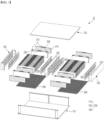
- FIG. 1 is an exploded perspective view of a battery pack 10 according to a first embodiment of the present invention.
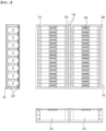
- FIG. 2 is a view illustrating an arrangement structure of first and second heat absorbers 310 and 320 provided in the battery pack 10 of the present invention.
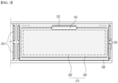
- FIG. 3 is a view illustrating an arrangement structure of the first and second heat absorbers 310 and 320 for one battery 200.
- the battery pack 10 of the present invention includes a pack case 100 and a plurality of batteries 200 accommodated in the pack case 100.
- the illustrated pack case 100 includes a main case 110 having a "U" cross-sectional shape, an upper case 120 coupled to an open surface of the main case 110, and a pair of side cases 130.
- the battery 200 is a secondary battery having a prismatic case shape, and a unidirectional secondary battery in which positive and negative electrode terminals 210 are disposed together on an upper surface is shown.
- a venting device 220 for discharging excessive internal pressure is provided between the electrode terminals 210 on an upper surface of the battery 200.
- the battery pack 10 of the present invention includes two types of heat absorbers 310 and 320.
- the first heat absorber 310 is a heat absorber disposed between the plurality of batteries 200. That is, in the illustrated embodiment, the plurality of batteries 200 are arranged in a line in a thickness direction, and thus the first heat absorbers 310 are in contact with the front and rear surfaces of the battery 200.
- the second heat absorbers 320 are heat absorbers disposed on both side surfaces of each of the plurality of batteries 200. Accordingly, the four (front, rear, left, and right) surfaces of the battery 200 accommodated in the pack case 100 are surrounded by the heat absorbers 310 and 320.
- the first and second heat absorbers 310 and 320 in contact with the battery 200 each include an absorbent material 330 impregnated with a liquid vaporized by absorbing heat generated by the battery 200, and an exterior material 340 for sealing and accommodating the absorbent material 330 in a liquid-absorbed state.
- the first and second heat absorbers 310 and 320 primarily perform a heat insulating function of suppressing the heat transfer between adjacent batteries 200.
- the first and second heat absorbers 310 and 320 secondarily perform a heat absorbing function of absorbing the heat generated in the battery 200 to prevent overheating.
- the internal pressure (vapor pressure) of the exterior material 340 rises.
- the exterior material 340 fractures and gas is ejected, thereby lowering the temperature of a high-temperature gas and the temperature of flames generated from the nearby overheated batteries 200. Accordingly, the first and second heat absorbers 310 and 320 may finally perform a fire extinguishing function.
- the absorbent material 330 may be an absorbent material including a super absorbent matrix, for example, a super absorbent polymer (SAP) or a super absorbent fiber (SAF).
- SAP super absorbent polymer
- SAF super absorbent fiber
- the super absorbent matrix is porous or fibrous and exhibits a capillary action, and thus it is possible to absorb a large amount of liquid, and SAFs may be made into a fiber form, such as a nonwoven fabric, by processing SAPs.
- SAP may include at least one selected from the group consisting of polyacrylic acid, a polyacrylic salt, a polyacrylate graft polymer, starch, crosslinked carboxymethylated cellulose, an acrylic acid copolymer, a hydrolyzed starch-acrylonitrile graft copolymer, a starch-acrylic acid graft copolymer, a saponified vinyl acetate-acrylic acid ester copolymer, a hydrolyzed acrylonitrile copolymer, a hydrolyzed acrylamide copolymer, an ethylene-maleic anhydride copolymer, an isobutylene-maleic anhydride copolymer, polyvinylsulfonic acid, polyvinylphosphonic acid, polyvinyl phosphoric acid, polyvinyl sulfuric
- the type of acrylic acid copolymer used as the SAP in the present invention is not particularly limited, but preferably, the acrylic acid copolymer may be a copolymer including at least one comonomer selected from the group consisting of an acrylic acid monomer, maleic acid, itaconic acid, acrylamide, 2-acrylamide-2-methylpropanesulfonic acid, 2-(meth)acryloylethanesulfonic acid, 2-hydroxyethyl(meth)acrylate, and styrenesulfonic acid.
- the amount of water absorbed by the SAP may be in a range of 10 g/g to 500 g/g and preferably 50 g/g to 200 g/g, but the present invention is not limited thereto. That is, 10 g to 500 g of water, preferably, 50 g to 200 g, may be absorbed per 1 g of the SAP.
- the duration of a cooling effect may be improved as the amount of water absorbed by the SAP is increased.
- the amount of water absorbed by the SAP exceeds 500 g/g, since the fluidity of the SAP increases, it may be difficult to maintain a shape of the SAP, which makes effective cooling impossible, and when the amount of water absorbed by the SAP is less than 10 g/g, the duration of a cooling effect is too short, which makes it ineffective.
- the liquid impregnated in the absorbent material 330 may be water.
- Water is a material with the highest specific heat and latent heat among readily available liquids. Therefore, since the water contained in the absorbent material 330 absorbs a lot of heat during a process in which a temperature rises to the boiling point to cause a phase change to gas, water is suitable for application as a liquid accommodated in the first and second heat absorbers 310 and 320 of the present invention.
- an additive capable of enhancing a fire extinguishing function may be mixed with the water impregnated in the absorbent material 330.
- the additive mixed with water may be a material for lowering the surface tension of water or may be a fire extinguishing agent.
- the material for lowering the surface tension of water may include a wetting agent or a surfactant.
- a fire extinguishing agent is a generic name for agents themselves that exert a fire extinguishing function, and various currently commercialized powder fire extinguishing agents or liquid fire extinguishing agents may be widely applied.
- a fire extinguishing agent under the brand name F-500 EA manufactured by Hazard Control Technologies, Inc.
- F-500 EA manufactured by Hazard Control Technologies, Inc.
- a large amount of liquid impregnated in the absorbent material 330 absorbs heat generated from the battery 200 and then vaporizes when a temperature thereof exceeds a boiling point. Due to an increase in volume due to a phase change from liquid to gas, the internal pressure of the exterior material 340 that seals the absorbent material 330 increases.
- a pouch made of a flexible laminate sheet may be used as the exterior material 340.
- the pouch which is the exterior material 340, is provided with a fragile portion 342 that preferentially fractures when the liquid impregnated in the absorbent material 330 vaporizes and the internal pressure increases.
- the laminate sheet may have a structure of three or more layers including an aluminum thin film layer, an inner resin layer formed inside the aluminum thin film layer, and an outer resin layer formed outside the aluminum thin film layer.
- the inner resin layer may be made of casted polypropylene (CPP) or polypropylene (PP)
- the outer resin layer may be made of polyethylene terephthalate (PET) or nylon.
- the fragile portion 342 may be formed in a structure that preferentially fractures due to an increase in internal pressure due to vaporization of the liquid. That is, the pouch 340 may be sealed by heat-sealing edges of the laminate sheet surrounding the absorbent material 330, and the fragile portion 342 may be formed in such a way that its heat-sealing strength is lower than that of surrounding portions.
- the fragile portion 342 may be formed by making the thickness thereof thinner than the surrounding portions, reducing strength by forming a notch, or locally removing the aluminum thin film layer for maintaining durability.
- the first heat absorber 310 may be disposed between the plurality of batteries 200.
- the first heat absorber 310 may also be provided between a sidewall of the pack case 100 and the battery 200.
- the first heat absorbers 310 are provided on the front and rear surfaces of all the batteries 200, thereby achieving uniform heat insulating, cooling, and fire extinguishing actions inside the battery pack 10.
- the battery 200 includes the venting device 220, and the fragile portion 342 provided in the pouch 340 of the first heat absorber 310 may be preferably positioned at a position corresponding to the venting device 220.
- the venting device 220 is disposed at the center of the upper surface of the battery 200, and correspondingly, the fragile portion 342 is positioned at the center of an upper portion of the first heat absorber 310.
- FIG. 4 is a cross-sectional view illustrating an arrangement structure of the plurality of batteries 200 and the first heat absorbers 310.
- the first heat absorber 310 is provided with the fragile portion 342, as shown in FIG. 4 , in a case in which a thermal runaway phenomenon occurs in any one battery 200 and the battery 200 overheats, when a liquid impregnated in the absorbent material 330 in the first heat absorber 310 absorbs heat and vaporizes, and the vaporized gas rises above a certain pressure, the fragile portion 342 of the first heat absorber 310 fractures, and gas is ejected.
- the gas ejected from the first heat absorber 310 cools the ignition sources and suppresses and extinguishes flames to considerably reduce the risk of fire in the battery pack 10.
- the first heat absorber 310 has been described in detail, but the configuration of the heat absorber itself is substantially the same as that of the second heat absorber 320.
- the second heat absorber 320 is different from the first heat absorber 310 in that the second heat absorber 320 is disposed on each of two side surfaces of the battery 200 and the position of the fragile portion 342 does not require a special condition.
- the second heat absorber 320 is in contact with each of two side surfaces of the battery 200 and is disposed on an inner surface of the side case 130 due to a structure of the pack case 100.
- FIG. 5 is a view illustrating an arrangement structure of the plurality of batteries 200 and the second heat absorbers 320. Referring to FIGS. 1 and 3 together, when a plurality of second heat absorbers 320 are provided, the second heat absorbers 320 may be uniformly disposed on the inner surface of the side case 130 to form rows and columns.
- the second heat absorbers 320 are installed in concave surfaces arranged in a grid structure on the inner surface of the side case 130 to form a uniform matrix structure, and accordingly, both side surfaces of all the batteries 200 have an equal contact area with the second heat absorber 320.
- a side plate 140 is disposed between the columns of the battery 200, and the plurality of second heat absorbers 320 are disposed in uniform rows and columns on an inner surface of the side plate 140 to be in contact with inner side surfaces of the batteries 200 (based on the pack case). Accordingly, side surfaces of all the batteries 200 in the battery pack 10 are in uniform contact with the second heat absorbers 320.
- a rib structure 150 having a grid shape is formed on the inner surface of the side case 130 and the side plate 140.
- the structural rigidity of the side case 130 and the side plate 140 is enhanced due to the rib structure 150 connected vertically and horizontally to protrude.
- a plurality of concave surfaces 152 forming rows and columns are formed on the inner surface of the side case 130 and the side plate 140 due to the rib structure 150 having a grid shape.
- the second heat absorber 320 is inserted and disposed in the concave surface 152.
- the second heat absorber 320 may have a thickness so as to not protrude out of the concave surface 152, and accordingly, the plurality of second heat absorbers 320 may be mounted in the battery pack 10 in a space efficient manner without increasing the size of the pack case 100.
- the plurality of second heat absorbers 320 are uniformly distributed and disposed in a matrix structure forming rows and columns.
- the second heat absorber 320 closest to the overheated battery 200 first exerts a heat absorbing function and a fire extinguishing function, and subsequently, as heat is transferred, other second heat absorbers 320 operate.
- the plurality of second heat absorbers 320 are disposed in a distributed manner, it is advantageous to maintain thermal management of the battery pack 10 for a longer time as compared with when one large-capacity heat absorber fractures once to terminate its function once.
- the illustrated battery pack 10 includes a water-cooled heat sink assembly 350, which absorbs heat, on an inner bottom of the main case 110, and the heat sink assembly 350 performs a function of absorbing and cooling heat through the bottom surface of the accommodated battery 200.
- FIG. 6 is an exploded perspective view of a battery pack 10 according to a second embodiment of the present invention.
- a plurality of batteries 200 are accommodated in a pack case 100 to form one or more columns, and a venting guide 400 is provided on upper surfaces of the batteries 200 and integrally coupled to venting devices 220 provided to form a column.
- FIG. 7 is a view illustrating a coupling structure of the venting guide 400 for the plurality of batteries 200.
- the venting guide 400 separates the venting device 220 from positive and negative electrode terminals 210 disposed on an upper surface of the battery 200. That is, one venting guide 400 is mounted in a structure covering the venting devices 220 for the plurality of batteries 200 forming a column, and accordingly, the central venting device 220 covered by the venting guide 400 is separated from the positive and negative electrode terminals 210 disposed at left and right sides of the venting device 220
- venting guide 400 is provided with a gas outlet 410 communicating with the venting device 220, the electrode terminal 210 and the venting device 220 are not completely isolated spatially. Since a discharge path in the venting device 220 is guided upward by the gas outlet 410, damage to the electrode terminal 210 due to thermal runaway can be prevented or at least delayed.
- FIG. 8 is a cross-sectional view illustrating the coupling structure along cutting line A-A' of FIG. 7 .
- an exterior material 340 of a first heat absorber 310 may be a pouch 340.
- the first heat absorber 310 may include a fragile portion 342 that preferentially fractures when a liquid impregnated in an absorbent material 330 of the first heat absorber 310 vaporizes and the internal pressure increases.
- the fragile portion 342 of the first heat absorber 310 may be positioned in a direction toward the venting guide 400.
- the venting guide 400 is provided with a steam outlet 420 communicating with the fragile portion 342 of the first heat absorber 310.
- the steam outlet 420 may also be provided between every adjacent outlets 410 among the gas outlets 410.
- the steam outlet 420 is disposed between every adjacent outlets 410 among the gas outlets 410 communicating with the venting device 220. Therefore, when thermal runaway occurs in any one battery 200 and high-temperature gas or flames are ejected from the venting device 220, a vaporized liquid component of the first heat absorber 310 in contact with the overheated battery 200 fractures the fragile portion 342 to eject steam, and discharge paths of the liquid component and the steam are guided to the gas outlet 410 and the steam outlet 420 of the venting guide 400 so that the liquid component and the steam are smoothly mixed.
- the battery pack 10 of the second embodiment includes the venting guide 400 that guides a discharge path of gas and steam in a set direction. Accordingly, damage to the electrode terminal 210 caused by high-temperature gas and flames is reduced, and a safety function of cooling and extinguishing gas and flames is enhanced.
- battery pack 100 pack case 110: main case 120: upper case 130: side case 140: side plate 150: rib structure 152: concave surface 200: battery 210: electrode terminal 220: venting device 310: first heat absorber 320: second heat absorber 330: absorbent material 340: exterior material (pouch) 342: fragile portion 350: heat sink assembly 400: venting guide 410: gas outlet 420: steam outlet
Landscapes
- Chemical & Material Sciences (AREA)
- Chemical Kinetics & Catalysis (AREA)
- Electrochemistry (AREA)
- General Chemical & Material Sciences (AREA)
- Engineering & Computer Science (AREA)
- Manufacturing & Machinery (AREA)
- Battery Mounting, Suspending (AREA)
- Gas Exhaust Devices For Batteries (AREA)
- Secondary Cells (AREA)
Abstract
Description
- The present invention relates to a battery pack capable of suppressing a thermal propagation phenomenon in which other nearby secondary batteries are consecutively overheated when thermal runaway occurs.
- This application claims the benefit of priority based on
Korean Patent Application No. 10-2022-00247695, filed on April 18, 2022 Korean Patent Application No. 10-2022-0183986, filed on December 26, 2022 - Secondary batteries are rechargeable unlike primary batteries, and are being researched and developed a lot due to their compact size and high capacity potential. The demand for secondary batteries as energy sources is increasing more rapidly due to technology development and an increase in demand for mobile devices and also due to electric vehicles and energy storage systems that are emerging in line with the needs of the times for environmental protection.
- Secondary batteries are classified into coin type batteries, cylindrical type batteries, prismatic type batteries, and pouch type batteries according to the shape of a battery case. In such a secondary battery, an electrode assembly mounted in a battery case is a chargeable or dischargeable power generating device having a structure in which an electrode and a separator are stacked.
- Since secondary batteries are required to be continuously used for a long time, it is necessary to effectively control the heat generated during a charging or discharging process. When the cooling of secondary batteries is not smoothly performed, a positive feedback chain reaction, in which an increase in temperature causes an increase in current, and the increase in current causes the temperature to rise again, occurs, eventually leading to a catastrophic state of thermal runaway.
- Also, when secondary batteries are grouped in the form of a module or a pack, a thermal propagation phenomenon occurs in which other nearby secondary batteries are consecutively overheated due to thermal runaway occurring in one secondary battery. Furthermore, since there is a high risk of fire due to ignition sources such as a combustible gas ejected from an overheated secondary battery and a heating electrode, it is necessary to suppress such risk of ignition.
- (Patent Document 001)
Korean Patent Publication No. 10-2021-0077410 (published on June 25, 2021 - An object of the present invention is to provide a battery pack capable of effectively suppressing and preventing a thermal propagation phenomenon in which heat due to thermal runaway generated in a secondary battery propagates to nearby secondary batteries.
- However, the technical objects to be solved by the present invention are not limited to the above-described object, and other objects not described herein will be clearly understood by those skilled in the art from the following descriptions of the present invention.
- According to the present invention, there is provided is a battery pack including a pack case, a plurality of batteries accommodated in the pack case, a first heat absorber disposed between the plurality of batteries, and a second heat absorber disposed on each of two side surfaces of each of the plurality of batteries, wherein the first heat absorber and the second heat absorber each include an absorbent material impregnated with a liquid vaporized by heat generated from the battery, and an exterior material in which the absorbent material in a liquid-absorbed state is accommodated.
- The first heat absorber may be disposed between every adjacent batteries among the plurality of batteries.
- The exterior material of each of the first heat absorber and the second heat absorber may be a pouch, and the pouch may be provided with a fragile portion that preferentially fractures when the liquid impregnated in the absorbent material vaporizes and an internal pressure thereof increases.
- The absorbent material may be a super absorbent matrix. For example, the super absorbent matrix may include a super absorbent polymer (SAP) or a super absorbent fiber (SAF).
- The liquid may be water mixed with an additive, and the additive may be a material for lowering the surface tension of water or a fire extinguishing agent.
- The battery may include a venting device, and the fragile portion provided in the pouch of the first heat absorber may be disposed at a position corresponding to the venting device.
- The second heat absorber may be disposed on an inner surface of a side case of the pack case.
- The second heat absorber may be provided as a plurality of second heat absorbers, and the plurality of second heat absorbers may be uniformly disposed on the inner surface of the side case to form rows and columns.
- The plurality of batteries may be accommodated in the pack case to form a plurality of columns, a side plate may be disposed between the columns of the batteries, and the second heat absorber may be provided as a plurality of second heat absorbers so that the second heat absorbers are uniformly disposed in contact with side surfaces of the batteries on an inner surface of the side plate to form rows and columns.
- A rib structure having a grid shape may be provided on the inner surface of the side case or the inner surface of the side plate, the second heat absorbers may be disposed in concave surfaces formed to form rows and columns due to the rib structure, and the second heat absorber may not protrude out of the concave surface.
- The plurality of batteries may be accommodated in the pack case to form one or more columns, a venting device may be provided on an upper surface of each battery, and a venting guide may be provided to be integrally coupled to the venting devices of the batteries forming the columns.
- The venting guide may separate the venting device from an electrode terminal disposed on the upper surface of the battery.
- The exterior material of the first heat absorber may be a pouch, and the pouch of the first heat absorber may be provided with a fragile portion that preferentially fractures when the liquid impregnated in the absorbent material vaporizes and an internal pressure thereof increases. Thus, the fragile portion of the first heat absorber may be positioned in a direction toward the venting guide. The venting guide may include gas outlets communicating with the venting devices, and a steam outlet communicating with the fragile portion of the first heat absorber.
- The first heat absorber may be disposed between every adjacent batteries among the plurality of batteries, and the steam outlet may be provided between every adjacent outlets among the gas outlets.
- According to a battery pack of the present invention having such a configuration, heat is rapidly absorbed and dispersed in an environment in which a temperature rapidly rises as in normal rapid charging, thereby suppressing the occurrence of thermal runaway in advance and maintaining performance and lifetime without a large increase in temperature.
- According to the present invention, when a thermal runaway phenomenon occurs in any one secondary battery, a liquid impregnated in an absorbent material in a heat absorbing pouch absorbs heat and vaporizes. When the vaporized gas rises above a certain pressure, the gas fractures the heat absorbing pouch and is ejected to cool ignition sources such as an inflammable gas ejected from an overheated battery and a heating electrode and suppress flames, thereby considerably reducing a thermal propagation phenomenon with respect to nearby secondary batteries and the risk of fire.
- In addition, a battery pack of the present invention has functions of absorbing heat, insulating heat, and extinguishing fires between and on side surfaces of densely packed secondary batteries, thereby rapidly dispersing the excess energy of the secondary batteries in all directions to delay a trigger time for thermal runaway.
- However, the technical effects obtainable through the present invention are not limited to the above-described effects, and other effects not described herein will be clearly understood by those skilled in the art from the following descriptions of the present invention.
- The accompanying drawings illustrate exemplary embodiments of the present invention and, together with the detailed description of the present invention, serve to provide further understanding of the technical spirit of the present invention. However, the present invention is not to be construed as being limited to the drawings.
-
FIG. 1 is an exploded perspective view of a battery pack according to a first embodiment of the present invention. -
FIG. 2 is a view illustrating an arrangement structure of first and second heat absorbers provided in the battery pack of the present invention. -
FIG. 3 is a view illustrating an arrangement structure of the first and second heat absorbers for one battery. -
FIG. 4 is a cross-sectional view illustrating an arrangement structure of a plurality of batteries and first heat absorbers. -
FIG. 5 is a cross-sectional view illustrating an arrangement structure of the plurality of batteries and second heat absorbers. -
FIG. 6 is an exploded perspective view of a battery pack according to a second embodiment of the present invention. -
FIG. 7 is a view illustrating a coupling structure of a venting guide for a plurality of batteries. -
FIG. 8 is a cross-sectional view illustrating the coupling structure along cutting line A-A' ofFIG. 7 . - Since the present invention may be variously changed and have various embodiments, specific embodiments will be described in detail below.
- However, it should be understood that there is no intention to limit the present invention to particular embodiments, and on the contrary, the present invention is to cover all modifications, equivalents, and alternatives falling within the spirit and scope of the present invention.
- In this application, it should be understood that terms such as "include" and "have" are intended to indicate that there is a feature, number, step, operation, component, part, or a combination thereof described in the specification, and they do not exclude in advance the possibility of the presence or addition of one or more other features or numbers, steps, operations, components, parts or combinations thereof.
- Also, when a first portion such as a layer, a film, an area, a plate, etc. is referred to as being "on" a second portion, this includes not only the case where the first portion is "directly on" the second portion, but also the case where still a third portion is interposed therebetween. On the other hand, when a first portion such as a layer, a film, an area, a plate, etc. is referred to as being "under" a second portion, this includes not only the case where the first portion is "directly under" the second portion, but also the case where a third portion is interposed therebetween. In addition, to be disposed "on" in the present application may include the case of being disposed at the bottom as well as the top.
- The present invention relates to a battery pack. In an example, the battery pack includes a pack case, a plurality of batteries accommodated in the pack case, a first heat absorber disposed between the plurality of batteries, and a second heat absorber disposed on each of two side surfaces of each of the plurality of batteries.
- Here, the first heat absorber and the second heat absorber each include an absorbent material impregnated with a liquid vaporized by heat generated from the battery, and an exterior material in which the absorbent material in a liquid-absorbed state is accommodated.
- Therefore, according to the present invention, through a heat absorbing action of the first and second heat absorbers in contact with the battery, heat is rapidly absorbed and dispersed in an environment in which a temperature rapidly rises as in normal rapid charging, thereby suppressing the occurrence of thermal runaway and maintaining performance and lifetime without a large increase in temperature. In particular, the first and second heat absorbers can absorb heat in all directions of the battery by coming in contact with the front and rear surfaces and both side surfaces of the battery, thereby effectively suppressing an increase in temperature.
- In addition, according to the present invention, when a thermal runaway phenomenon occurs in any one battery in the battery pack, a liquid impregnated in the absorbent material in the heat absorber absorbs heat and vaporizes. When the vaporized gas rises above a certain pressure, the gas fractures the heat absorber and is ejected to cool ignition sources such as an inflammable gas ejected from an overheated battery and a heating electrode and suppress flames, thereby considerably reducing the risk of fire in the battery pack.
- Hereinafter, specific embodiments of a battery pack of the present invention will be described with reference to the accompanying drawings. For reference, front and rear directions or up, down, left, and right directions for designating relative positions used in the following description are intended to help the understanding of the present invention and are based on directions shown in the drawings unless otherwise specified.
-
FIG. 1 is an exploded perspective view of abattery pack 10 according to a first embodiment of the present invention.FIG. 2 is a view illustrating an arrangement structure of first andsecond heat absorbers battery pack 10 of the present invention.FIG. 3 is a view illustrating an arrangement structure of the first andsecond heat absorbers battery 200. - As shown in the drawings, the
battery pack 10 of the present invention includes apack case 100 and a plurality ofbatteries 200 accommodated in thepack case 100. The illustratedpack case 100 includes amain case 110 having a "U" cross-sectional shape, anupper case 120 coupled to an open surface of themain case 110, and a pair ofside cases 130. Thebattery 200 is a secondary battery having a prismatic case shape, and a unidirectional secondary battery in which positive andnegative electrode terminals 210 are disposed together on an upper surface is shown. In addition, aventing device 220 for discharging excessive internal pressure is provided between theelectrode terminals 210 on an upper surface of thebattery 200. - The
battery pack 10 of the present invention includes two types ofheat absorbers first heat absorber 310 is a heat absorber disposed between the plurality ofbatteries 200. That is, in the illustrated embodiment, the plurality ofbatteries 200 are arranged in a line in a thickness direction, and thus thefirst heat absorbers 310 are in contact with the front and rear surfaces of thebattery 200. Thesecond heat absorbers 320 are heat absorbers disposed on both side surfaces of each of the plurality ofbatteries 200. Accordingly, the four (front, rear, left, and right) surfaces of thebattery 200 accommodated in thepack case 100 are surrounded by theheat absorbers - The first and
second heat absorbers battery 200 each include anabsorbent material 330 impregnated with a liquid vaporized by absorbing heat generated by thebattery 200, and anexterior material 340 for sealing and accommodating theabsorbent material 330 in a liquid-absorbed state. - The first and
second heat absorbers adjacent batteries 200. The first andsecond heat absorbers battery 200 to prevent overheating. In addition, as a liquid vaporizes through a heat absorbing action, the internal pressure (vapor pressure) of theexterior material 340 rises. When the internal pressure exceeds a certain pressure, theexterior material 340 fractures and gas is ejected, thereby lowering the temperature of a high-temperature gas and the temperature of flames generated from the nearbyoverheated batteries 200. Accordingly, the first andsecond heat absorbers - In one embodiment of the present invention, the
absorbent material 330 may be an absorbent material including a super absorbent matrix, for example, a super absorbent polymer (SAP) or a super absorbent fiber (SAF). The super absorbent matrix is porous or fibrous and exhibits a capillary action, and thus it is possible to absorb a large amount of liquid, and SAFs may be made into a fiber form, such as a nonwoven fabric, by processing SAPs. - In the present invention, specific types of the SAP and the SAF produced therefrom are not particularly limited, and any material having an excellent ability to absorb a fluid, particularly, water, may be used without limitation. Examples of the SAP may include at least one selected from the group consisting of polyacrylic acid, a polyacrylic salt, a polyacrylate graft polymer, starch, crosslinked carboxymethylated cellulose, an acrylic acid copolymer, a hydrolyzed starch-acrylonitrile graft copolymer, a starch-acrylic acid graft copolymer, a saponified vinyl acetate-acrylic acid ester copolymer, a hydrolyzed acrylonitrile copolymer, a hydrolyzed acrylamide copolymer, an ethylene-maleic anhydride copolymer, an isobutylene-maleic anhydride copolymer, polyvinylsulfonic acid, polyvinylphosphonic acid, polyvinyl phosphoric acid, polyvinyl sulfuric acid, sulfonated polystyrene, polyvinylamine, polydialkylaminoalkyl(meth)acrylamide, polyethyleneimine, polyallylamine, polyallylguanidine, polydimethyldiallylammonium hydroxide, a quaternized polystyrene derivative, guanidine-modified polystyrene, quaternized poly((meth)acrylamide, oolyvinylguanidine, and a mixture thereof and may preferably include at least one selected from the group consisting of a crosslinked polyacrylic salt, crosslinked polyacrylic acid, and a crosslinked acrylic acid copolymer, but the present invention is not limited thereto.
- The type of acrylic acid copolymer used as the SAP in the present invention is not particularly limited, but preferably, the acrylic acid copolymer may be a copolymer including at least one comonomer selected from the group consisting of an acrylic acid monomer, maleic acid, itaconic acid, acrylamide, 2-acrylamide-2-methylpropanesulfonic acid, 2-(meth)acryloylethanesulfonic acid, 2-hydroxyethyl(meth)acrylate, and styrenesulfonic acid.
- In the present invention, the amount of water absorbed by the SAP may be in a range of 10 g/g to 500 g/g and preferably 50 g/g to 200 g/g, but the present invention is not limited thereto. That is, 10 g to 500 g of water, preferably, 50 g to 200 g, may be absorbed per 1 g of the SAP.
- In the present invention, the duration of a cooling effect may be improved as the amount of water absorbed by the SAP is increased. However, when the amount of water absorbed by the SAP exceeds 500 g/g, since the fluidity of the SAP increases, it may be difficult to maintain a shape of the SAP, which makes effective cooling impossible, and when the amount of water absorbed by the SAP is less than 10 g/g, the duration of a cooling effect is too short, which makes it ineffective.
- In one embodiment of the present invention, the liquid impregnated in the
absorbent material 330 may be water. Water is a material with the highest specific heat and latent heat among readily available liquids. Therefore, since the water contained in theabsorbent material 330 absorbs a lot of heat during a process in which a temperature rises to the boiling point to cause a phase change to gas, water is suitable for application as a liquid accommodated in the first andsecond heat absorbers - In addition, an additive capable of enhancing a fire extinguishing function may be mixed with the water impregnated in the
absorbent material 330. For example, the additive mixed with water may be a material for lowering the surface tension of water or may be a fire extinguishing agent. Examples of the material for lowering the surface tension of water may include a wetting agent or a surfactant. When the surface tension of water is reduced, the penetration effect of water increases, thereby enhancing the fire extinguishing effect on high-temperature ignition sources such as heating electrodes and ignition particles. - A fire extinguishing agent is a generic name for agents themselves that exert a fire extinguishing function, and various currently commercialized powder fire extinguishing agents or liquid fire extinguishing agents may be widely applied. For example, a fire extinguishing agent under the brand name F-500 EA (manufactured by Hazard Control Technologies, Inc.) may be added to water.
- Meanwhile, a large amount of liquid impregnated in the
absorbent material 330, for example, water, absorbs heat generated from thebattery 200 and then vaporizes when a temperature thereof exceeds a boiling point. Due to an increase in volume due to a phase change from liquid to gas, the internal pressure of theexterior material 340 that seals theabsorbent material 330 increases. - A pouch made of a flexible laminate sheet may be used as the
exterior material 340. The pouch, which is theexterior material 340, is provided with afragile portion 342 that preferentially fractures when the liquid impregnated in theabsorbent material 330 vaporizes and the internal pressure increases. - The laminate sheet may have a structure of three or more layers including an aluminum thin film layer, an inner resin layer formed inside the aluminum thin film layer, and an outer resin layer formed outside the aluminum thin film layer. For example, the inner resin layer may be made of casted polypropylene (CPP) or polypropylene (PP), and the outer resin layer may be made of polyethylene terephthalate (PET) or nylon.
- By locally lowering the sealing strength of the
pouch 340, thefragile portion 342 may be formed in a structure that preferentially fractures due to an increase in internal pressure due to vaporization of the liquid. That is, thepouch 340 may be sealed by heat-sealing edges of the laminate sheet surrounding theabsorbent material 330, and thefragile portion 342 may be formed in such a way that its heat-sealing strength is lower than that of surrounding portions. For example, thefragile portion 342 may be formed by making the thickness thereof thinner than the surrounding portions, reducing strength by forming a notch, or locally removing the aluminum thin film layer for maintaining durability. - As shown in
FIGS. 1 and2 , thefirst heat absorber 310 may be disposed between the plurality ofbatteries 200. In addition, thefirst heat absorber 310 may also be provided between a sidewall of thepack case 100 and thebattery 200. As described above, thefirst heat absorbers 310 are provided on the front and rear surfaces of all thebatteries 200, thereby achieving uniform heat insulating, cooling, and fire extinguishing actions inside thebattery pack 10. - Meanwhile, as described above, the
battery 200 includes theventing device 220, and thefragile portion 342 provided in thepouch 340 of thefirst heat absorber 310 may be preferably positioned at a position corresponding to theventing device 220. In the illustrated embodiment, theventing device 220 is disposed at the center of the upper surface of thebattery 200, and correspondingly, thefragile portion 342 is positioned at the center of an upper portion of thefirst heat absorber 310. -
FIG. 4 is a cross-sectional view illustrating an arrangement structure of the plurality ofbatteries 200 and thefirst heat absorbers 310. As described above, since thefirst heat absorber 310 is provided with thefragile portion 342, as shown inFIG. 4 , in a case in which a thermal runaway phenomenon occurs in any onebattery 200 and thebattery 200 overheats, when a liquid impregnated in theabsorbent material 330 in thefirst heat absorber 310 absorbs heat and vaporizes, and the vaporized gas rises above a certain pressure, thefragile portion 342 of thefirst heat absorber 310 fractures, and gas is ejected. During a process in which ignition sources such as a combustible gas generated by theoverheated battery 200 and a heating electrode are released through theventing device 220, the gas ejected from thefirst heat absorber 310 cools the ignition sources and suppresses and extinguishes flames to considerably reduce the risk of fire in thebattery pack 10. - In the above, the
first heat absorber 310 has been described in detail, but the configuration of the heat absorber itself is substantially the same as that of thesecond heat absorber 320. However, thesecond heat absorber 320 is different from thefirst heat absorber 310 in that thesecond heat absorber 320 is disposed on each of two side surfaces of thebattery 200 and the position of thefragile portion 342 does not require a special condition. - The
second heat absorber 320 is in contact with each of two side surfaces of thebattery 200 and is disposed on an inner surface of theside case 130 due to a structure of thepack case 100.FIG. 5 is a view illustrating an arrangement structure of the plurality ofbatteries 200 and thesecond heat absorbers 320. Referring toFIGS. 1 and3 together, when a plurality ofsecond heat absorbers 320 are provided, thesecond heat absorbers 320 may be uniformly disposed on the inner surface of theside case 130 to form rows and columns. In the illustrated embodiment, thesecond heat absorbers 320 are installed in concave surfaces arranged in a grid structure on the inner surface of theside case 130 to form a uniform matrix structure, and accordingly, both side surfaces of all thebatteries 200 have an equal contact area with thesecond heat absorber 320. - When the plurality of
batteries 200 are accommodated in thepack case 100 to form a plurality of columns (two columns in the illustrated embodiment) as in the illustrated embodiment, aside plate 140 is disposed between the columns of thebattery 200, and the plurality ofsecond heat absorbers 320 are disposed in uniform rows and columns on an inner surface of theside plate 140 to be in contact with inner side surfaces of the batteries 200 (based on the pack case). Accordingly, side surfaces of all thebatteries 200 in thebattery pack 10 are in uniform contact with thesecond heat absorbers 320. - Here, referring to
FIGS. 1 ,3 , and5 , a rib structure 150 having a grid shape is formed on the inner surface of theside case 130 and theside plate 140. The structural rigidity of theside case 130 and theside plate 140 is enhanced due to the rib structure 150 connected vertically and horizontally to protrude. In addition, a plurality of concave surfaces 152 forming rows and columns are formed on the inner surface of theside case 130 and theside plate 140 due to the rib structure 150 having a grid shape. Thesecond heat absorber 320 is inserted and disposed in the concave surface 152. Thesecond heat absorber 320 may have a thickness so as to not protrude out of the concave surface 152, and accordingly, the plurality ofsecond heat absorbers 320 may be mounted in thebattery pack 10 in a space efficient manner without increasing the size of thepack case 100. - Due to the rib structure 150, the plurality of
second heat absorbers 320 are uniformly distributed and disposed in a matrix structure forming rows and columns. When thesecond heat absorbers 320 are disposed in a distributed manner, thesecond heat absorber 320 closest to theoverheated battery 200 first exerts a heat absorbing function and a fire extinguishing function, and subsequently, as heat is transferred, othersecond heat absorbers 320 operate. As described above, since the plurality ofsecond heat absorbers 320 are disposed in a distributed manner, it is advantageous to maintain thermal management of thebattery pack 10 for a longer time as compared with when one large-capacity heat absorber fractures once to terminate its function once. - For reference, the illustrated
battery pack 10 includes a water-cooledheat sink assembly 350, which absorbs heat, on an inner bottom of themain case 110, and theheat sink assembly 350 performs a function of absorbing and cooling heat through the bottom surface of the accommodatedbattery 200. -
FIG. 6 is an exploded perspective view of abattery pack 10 according to a second embodiment of the present invention. In thebattery pack 10 according to the second embodiment of the present invention, a plurality ofbatteries 200 are accommodated in apack case 100 to form one or more columns, and a ventingguide 400 is provided on upper surfaces of thebatteries 200 and integrally coupled to ventingdevices 220 provided to form a column. -
FIG. 7 is a view illustrating a coupling structure of the ventingguide 400 for the plurality ofbatteries 200. As shown in the drawing, the ventingguide 400 separates theventing device 220 from positive andnegative electrode terminals 210 disposed on an upper surface of thebattery 200. That is, one ventingguide 400 is mounted in a structure covering theventing devices 220 for the plurality ofbatteries 200 forming a column, and accordingly, thecentral venting device 220 covered by the ventingguide 400 is separated from the positive andnegative electrode terminals 210 disposed at left and right sides of theventing device 220 - However, since the venting
guide 400 is provided with agas outlet 410 communicating with theventing device 220, theelectrode terminal 210 and theventing device 220 are not completely isolated spatially. Since a discharge path in theventing device 220 is guided upward by thegas outlet 410, damage to theelectrode terminal 210 due to thermal runaway can be prevented or at least delayed. -
FIG. 8 is a cross-sectional view illustrating the coupling structure along cutting line A-A' ofFIG. 7 . As described in the first embodiment, anexterior material 340 of afirst heat absorber 310 may be apouch 340. In this case, thefirst heat absorber 310 may include afragile portion 342 that preferentially fractures when a liquid impregnated in anabsorbent material 330 of thefirst heat absorber 310 vaporizes and the internal pressure increases. - Also, the
fragile portion 342 of thefirst heat absorber 310 may be positioned in a direction toward the ventingguide 400. For example, when theventing device 220 is positioned at the center of an upper surface of thebattery 200, thefragile portion 342 of thefirst heat absorber 310 is also disposed at the center of an upper portion thereof, thereby allowing a steam discharge direction to be directed toward the ventingguide 400. Correspondingly, the ventingguide 400 is provided with asteam outlet 420 communicating with thefragile portion 342 of thefirst heat absorber 310. Here, when thefirst heat absorber 310 is disposed between everyadjacent batteries 200 among the plurality ofbatteries 200, thesteam outlet 420 may also be provided between everyadjacent outlets 410 among thegas outlets 410. - Referring to
FIG. 8 , thesteam outlet 420 is disposed between everyadjacent outlets 410 among thegas outlets 410 communicating with theventing device 220. Therefore, when thermal runaway occurs in any onebattery 200 and high-temperature gas or flames are ejected from theventing device 220, a vaporized liquid component of thefirst heat absorber 310 in contact with theoverheated battery 200 fractures thefragile portion 342 to eject steam, and discharge paths of the liquid component and the steam are guided to thegas outlet 410 and thesteam outlet 420 of the ventingguide 400 so that the liquid component and the steam are smoothly mixed. - As described above, the
battery pack 10 of the second embodiment includes the ventingguide 400 that guides a discharge path of gas and steam in a set direction. Accordingly, damage to theelectrode terminal 210 caused by high-temperature gas and flames is reduced, and a safety function of cooling and extinguishing gas and flames is enhanced. - The present invention has been described above in more detail through the drawings and embodiments. However, the configurations described in the drawings or the embodiments in the specification are merely embodiments of the present invention and do not represent all the technical ideas of the present invention. Thus, it is to be understood that there may be various equivalents and variations that can replace them at the time of filing the present application.
-
10: battery pack 100: pack case 110: main case 120: upper case 130: side case 140: side plate 150: rib structure 152: concave surface 200: battery 210: electrode terminal 220: venting device 310: first heat absorber 320: second heat absorber 330: absorbent material 340: exterior material (pouch) 342: fragile portion 350: heat sink assembly 400: venting guide 410: gas outlet 420: steam outlet
Claims (16)
- A battery pack comprising:a pack case;a plurality of batteries accommodated in the pack case;a first heat absorber disposed between the plurality of batteries; anda second heat absorber disposed on each of two side surfaces of each of the plurality of batteries,wherein the first heat absorber and the second heat absorber each include an absorbent material impregnated with a liquid vaporized by heat generated from the battery, and an exterior material in which the absorbent material in a liquid-absorbed state is accommodated.
- The battery pack of claim 1, wherein the first heat absorber is disposed between every adjacent batteries among the plurality of batteries.
- The battery pack of claim 1, wherein the exterior material of each of the first heat absorber and the second heat absorber is a pouch, and
the pouch is provided with a fragile portion that preferentially fractures when the liquid impregnated in the absorbent material vaporizes and an internal pressure thereof increases. - The battery pack of claim 3, wherein the absorbent material is a super absorbent matrix.
- The battery pack of claim 4, wherein the super absorbent matrix includes a super absorbent polymer (SAP) or a super absorbent fiber (SAF).
- The battery pack of claim 5, wherein the liquid is water mixed with an additive, and
the additive is a material for lowering a surface tension of water or a fire extinguishing agent. - The battery pack of claim 3, wherein the battery includes a venting device, and
the fragile portion provided in the pouch of the first heat absorber is disposed at a position corresponding to the venting device. - The battery pack of claim 1, wherein the second heat absorber is disposed on an inner surface of a side case of the pack case.
- The battery pack of claim 8, wherein the second heat absorber is provided as a plurality of second heat absorbers, and
the plurality of second heat absorbers are uniformly disposed on the inner surface of the side case to form rows and columns. - The battery pack of claim 1, wherein the plurality of batteries are accommodated in the pack case to form a plurality of columns,a side plate is disposed between the columns of the batteries, andthe second heat absorber is provided as a plurality of second heat absorbers so that the second heat absorbers are uniformly disposed in contact with side surfaces of the batteries on an inner surface of the side plate to form rows and columns.
- The battery pack of claim 9 or 10, wherein a rib structure having a grid shape is provided on the inner surface of the side case or the inner surface of the side plate,the second heat absorbers are disposed in concave surfaces formed to form rows and columns due to the rib structure, andthe second heat absorber does not protrude out of the concave surface.
- The battery pack of claim 1, wherein the plurality of batteries are accommodated in the pack case to form one or more columns,a venting device is provided on an upper surface of each battery, anda venting guide is provided to be integrally coupled to the venting devices of the batteries forming the columns.
- The battery pack of claim 12, wherein the venting guide separates the venting device from an electrode terminal disposed on the upper surface of the battery.
- The battery pack of claim 13, wherein the exterior material of the first heat absorber is a pouch, and
the pouch of the first heat absorber is provided with a fragile portion that preferentially fractures when the liquid impregnated in the absorbent material vaporizes and an internal pressure thereof increases. - The battery pack of claim 14, wherein the fragile portion of the first heat absorber is positioned in a direction toward the venting guide, and
the venting guide includes gas outlets communicating with the venting devices, and a steam outlet communicating with the fragile portion of the first heat absorber. - The battery pack of claim 15, wherein the first heat absorber is disposed between every adjacent batteries among the plurality of batteries, and
the steam outlet is provided between every adjacent outlets among the gas outlets.
Applications Claiming Priority (3)
| Application Number | Priority Date | Filing Date | Title |
|---|---|---|---|
| KR20220047695 | 2022-04-18 | ||
| KR1020220183986A KR20230148731A (en) | 2022-04-18 | 2022-12-26 | Battery pack |
| PCT/KR2023/004989 WO2023204523A1 (en) | 2022-04-18 | 2023-04-13 | Battery pack |
Publications (2)
| Publication Number | Publication Date |
|---|---|
| EP4318739A1 true EP4318739A1 (en) | 2024-02-07 |
| EP4318739A4 EP4318739A4 (en) | 2025-05-21 |
Family
ID=88420345
Family Applications (1)
| Application Number | Title | Priority Date | Filing Date |
|---|---|---|---|
| EP23792100.2A Pending EP4318739A4 (en) | 2022-04-18 | 2023-04-13 | Battery pack |
Country Status (4)
| Country | Link |
|---|---|
| US (1) | US20240258614A1 (en) |
| EP (1) | EP4318739A4 (en) |
| JP (1) | JP7655637B2 (en) |
| WO (1) | WO2023204523A1 (en) |
Families Citing this family (1)
| Publication number | Priority date | Publication date | Assignee | Title |
|---|---|---|---|---|
| WO2025158797A1 (en) * | 2024-01-24 | 2025-07-31 | 株式会社村田製作所 | Battery pack and manufacturing method therefor |
Family Cites Families (21)
| Publication number | Priority date | Publication date | Assignee | Title |
|---|---|---|---|---|
| US8318333B2 (en) * | 2007-10-15 | 2012-11-27 | Sony Corporation | Battery pack and method for producing the same |
| JP4900534B2 (en) | 2009-02-24 | 2012-03-21 | パナソニック株式会社 | Battery module and battery module assembly using the same |
| KR101058102B1 (en) * | 2009-12-18 | 2011-08-24 | 에스비리모티브 주식회사 | Battery pack |
| JP2011210619A (en) * | 2010-03-30 | 2011-10-20 | Sanyo Electric Co Ltd | Battery pack |
| KR101084224B1 (en) * | 2010-06-10 | 2011-11-17 | 에스비리모티브 주식회사 | Battery pack |
| JP2013157112A (en) * | 2012-01-27 | 2013-08-15 | Toshiba Corp | Battery pack |
| EP3321994B1 (en) | 2015-07-09 | 2023-03-08 | Vehicle Energy Japan Inc. | Cell module |
| KR102201278B1 (en) * | 2016-09-19 | 2021-01-08 | 삼성에스디아이 주식회사 | Rechargeable battery |
| CN108054460B (en) * | 2016-11-29 | 2021-03-05 | 北京科易动力科技有限公司 | Heat absorption and heat insulation structure of battery module |
| CN111033882B (en) * | 2017-09-22 | 2024-05-28 | 松下知识产权经营株式会社 | Battery Module |
| JP2020064755A (en) * | 2018-10-17 | 2020-04-23 | 株式会社日立製作所 | Battery pack |
| JP7155954B2 (en) | 2018-11-30 | 2022-10-19 | トヨタ自動車株式会社 | assembled battery |
| US20200403201A1 (en) * | 2019-06-21 | 2020-12-24 | All Cell Technologies, Llc | Apparatus and method for thermal runaway propagation prevention |
| CN112310533B (en) * | 2019-11-15 | 2022-03-01 | 宁德时代新能源科技股份有限公司 | Battery box and device |
| KR102914405B1 (en) | 2019-12-17 | 2026-01-19 | 삼성에스디아이 주식회사 | Battery Module |
| WO2021247778A1 (en) * | 2020-06-03 | 2021-12-09 | Wisk Aero Llc | Battery with selective phase change features |
| US11872423B2 (en) * | 2022-03-04 | 2024-01-16 | Ford Global Technologies, Llc | Battery thermal suppression systems |
| KR20230148890A (en) * | 2022-04-18 | 2023-10-26 | 주식회사 엘지에너지솔루션 | Prismatic secondary battery |
| KR20240052339A (en) * | 2022-10-14 | 2024-04-23 | 주식회사 엘지에너지솔루션 | Secondary battery module improved with satability of temperature in battery module |
| KR20240072645A (en) * | 2022-11-17 | 2024-05-24 | 주식회사 엘지에너지솔루션 | Secondary battery module improved with satability of temperature in battery module |
| KR20240084197A (en) * | 2022-12-06 | 2024-06-13 | 주식회사 엘지에너지솔루션 | Battery pack having venting duct integrated with lid |
-
2023
- 2023-04-13 EP EP23792100.2A patent/EP4318739A4/en active Pending
- 2023-04-13 US US18/290,046 patent/US20240258614A1/en active Pending
- 2023-04-13 JP JP2023568719A patent/JP7655637B2/en active Active
- 2023-04-13 WO PCT/KR2023/004989 patent/WO2023204523A1/en not_active Ceased
Also Published As
| Publication number | Publication date |
|---|---|
| US20240258614A1 (en) | 2024-08-01 |
| JP7655637B2 (en) | 2025-04-02 |
| JP2024521647A (en) | 2024-06-04 |
| EP4318739A4 (en) | 2025-05-21 |
| WO2023204523A1 (en) | 2023-10-26 |
Similar Documents
| Publication | Publication Date | Title |
|---|---|---|
| EP4329048B1 (en) | Prismatic secondary battery | |
| EP4325635B1 (en) | Battery pack with enhanced cooling performance | |
| EP4350846B1 (en) | Endothermic pouch assembly for secondary battery | |
| EP4322288A1 (en) | Prismatic secondary battery with heat absorber embedded therein | |
| US20240387917A1 (en) | Prismatic secondary battery | |
| US20250293347A1 (en) | Secondary battery module with improved module interior temperature stability | |
| US20240258614A1 (en) | Battery pack | |
| KR20230153919A (en) | Prismatic secondary battery including heat absorber | |
| KR20240010322A (en) | Battery pack | |
| KR20230148731A (en) | Battery pack | |
| EP4468497B1 (en) | Battery pack having cover-integrated venting duct | |
| US20260011813A1 (en) | Secondary Battery Module Having Improved Stability of Temperature Inside Module | |
| CN117378082A (en) | Prismatic secondary battery with built-in heat absorber | |
| KR20240010866A (en) | Battery pack | |
| CN117296188A (en) | Battery | |
| EP4336630A1 (en) | Secondary battery having enhanced safety | |
| KR20240013490A (en) | Safety enhanced battery block | |
| KR20240084194A (en) | Battery block having improved cold operation performance |
Legal Events
| Date | Code | Title | Description |
|---|---|---|---|
| STAA | Information on the status of an ep patent application or granted ep patent |
Free format text: STATUS: THE INTERNATIONAL PUBLICATION HAS BEEN MADE |
|
| PUAI | Public reference made under article 153(3) epc to a published international application that has entered the european phase |
Free format text: ORIGINAL CODE: 0009012 |
|
| STAA | Information on the status of an ep patent application or granted ep patent |
Free format text: STATUS: REQUEST FOR EXAMINATION WAS MADE |
|
| 17P | Request for examination filed |
Effective date: 20231102 |
|
| AK | Designated contracting states |
Kind code of ref document: A1 Designated state(s): AL AT BE BG CH CY CZ DE DK EE ES FI FR GB GR HR HU IE IS IT LI LT LU LV MC ME MK MT NL NO PL PT RO RS SE SI SK SM TR |
|
| A4 | Supplementary search report drawn up and despatched |
Effective date: 20250424 |
|
| RIC1 | Information provided on ipc code assigned before grant |
Ipc: H01M 50/105 20210101ALI20250416BHEP Ipc: H01M 50/211 20210101ALI20250416BHEP Ipc: H01M 50/383 20210101ALI20250416BHEP Ipc: H01M 50/342 20210101ALI20250416BHEP Ipc: H01M 50/24 20210101ALI20250416BHEP Ipc: H01M 50/143 20210101ALI20250416BHEP Ipc: H01M 10/647 20140101ALI20250416BHEP Ipc: H01M 10/613 20140101ALI20250416BHEP Ipc: H01M 10/6569 20140101ALI20250416BHEP Ipc: H01M 50/30 20210101ALI20250416BHEP Ipc: H01M 10/659 20140101AFI20250416BHEP |
|
| DAV | Request for validation of the european patent (deleted) | ||
| DAX | Request for extension of the european patent (deleted) | ||
| STAA | Information on the status of an ep patent application or granted ep patent |
Free format text: STATUS: EXAMINATION IS IN PROGRESS |
|
| 17Q | First examination report despatched |
Effective date: 20260112 |