EP4318729A1 - Battery cell side penetration test device and battery cell penetration test method using same - Google Patents
Battery cell side penetration test device and battery cell penetration test method using same Download PDFInfo
- Publication number
- EP4318729A1 EP4318729A1 EP22893188.7A EP22893188A EP4318729A1 EP 4318729 A1 EP4318729 A1 EP 4318729A1 EP 22893188 A EP22893188 A EP 22893188A EP 4318729 A1 EP4318729 A1 EP 4318729A1
- Authority
- EP
- European Patent Office
- Prior art keywords
- penetration
- unit
- battery cell
- penetration test
- test apparatus
- Prior art date
- Legal status (The legal status is an assumption and is not a legal conclusion. Google has not performed a legal analysis and makes no representation as to the accuracy of the status listed.)
- Pending
Links
Images


Classifications
-
- H—ELECTRICITY
- H01—ELECTRIC ELEMENTS
- H01M—PROCESSES OR MEANS, e.g. BATTERIES, FOR THE DIRECT CONVERSION OF CHEMICAL ENERGY INTO ELECTRICAL ENERGY
- H01M10/00—Secondary cells; Manufacture thereof
- H01M10/42—Methods or arrangements for servicing or maintenance of secondary cells or secondary half-cells
- H01M10/4285—Testing apparatus
-
- B—PERFORMING OPERATIONS; TRANSPORTING
- B21—MECHANICAL METAL-WORKING WITHOUT ESSENTIALLY REMOVING MATERIAL; PUNCHING METAL
- B21G—MAKING NEEDLES, PINS OR NAILS OF METAL
- B21G1/00—Making needles used for performing operations
- B21G1/08—Making needles used for performing operations of hollow needles or needles with hollow end, e.g. hypodermic needles, larding-needles
-
- G—PHYSICS
- G01—MEASURING; TESTING
- G01N—INVESTIGATING OR ANALYSING MATERIALS BY DETERMINING THEIR CHEMICAL OR PHYSICAL PROPERTIES
- G01N3/00—Investigating strength properties of solid materials by application of mechanical stress
- G01N3/30—Investigating strength properties of solid materials by application of mechanical stress by applying a single impulsive force, e.g. by falling weight
-
- H—ELECTRICITY
- H01—ELECTRIC ELEMENTS
- H01M—PROCESSES OR MEANS, e.g. BATTERIES, FOR THE DIRECT CONVERSION OF CHEMICAL ENERGY INTO ELECTRICAL ENERGY
- H01M10/00—Secondary cells; Manufacture thereof
- H01M10/42—Methods or arrangements for servicing or maintenance of secondary cells or secondary half-cells
- H01M10/48—Accumulators combined with arrangements for measuring, testing or indicating the condition of cells, e.g. the level or density of the electrolyte
-
- H—ELECTRICITY
- H01—ELECTRIC ELEMENTS
- H01M—PROCESSES OR MEANS, e.g. BATTERIES, FOR THE DIRECT CONVERSION OF CHEMICAL ENERGY INTO ELECTRICAL ENERGY
- H01M50/00—Constructional details or processes of manufacture of the non-active parts of electrochemical cells other than fuel cells, e.g. hybrid cells
- H01M50/20—Mountings; Secondary casings or frames; Racks, modules or packs; Suspension devices; Shock absorbers; Transport or carrying devices; Holders
- H01M50/204—Racks, modules or packs for multiple batteries or multiple cells
- H01M50/207—Racks, modules or packs for multiple batteries or multiple cells characterised by their shape
- H01M50/211—Racks, modules or packs for multiple batteries or multiple cells characterised by their shape adapted for pouch cells
-
- H—ELECTRICITY
- H01—ELECTRIC ELEMENTS
- H01M—PROCESSES OR MEANS, e.g. BATTERIES, FOR THE DIRECT CONVERSION OF CHEMICAL ENERGY INTO ELECTRICAL ENERGY
- H01M50/00—Constructional details or processes of manufacture of the non-active parts of electrochemical cells other than fuel cells, e.g. hybrid cells
- H01M50/20—Mountings; Secondary casings or frames; Racks, modules or packs; Suspension devices; Shock absorbers; Transport or carrying devices; Holders
- H01M50/204—Racks, modules or packs for multiple batteries or multiple cells
- H01M50/207—Racks, modules or packs for multiple batteries or multiple cells characterised by their shape
- H01M50/213—Racks, modules or packs for multiple batteries or multiple cells characterised by their shape adapted for cells having curved cross-section, e.g. round or elliptic
-
- Y—GENERAL TAGGING OF NEW TECHNOLOGICAL DEVELOPMENTS; GENERAL TAGGING OF CROSS-SECTIONAL TECHNOLOGIES SPANNING OVER SEVERAL SECTIONS OF THE IPC; TECHNICAL SUBJECTS COVERED BY FORMER USPC CROSS-REFERENCE ART COLLECTIONS [XRACs] AND DIGESTS
- Y02—TECHNOLOGIES OR APPLICATIONS FOR MITIGATION OR ADAPTATION AGAINST CLIMATE CHANGE
- Y02E—REDUCTION OF GREENHOUSE GAS [GHG] EMISSIONS, RELATED TO ENERGY GENERATION, TRANSMISSION OR DISTRIBUTION
- Y02E60/00—Enabling technologies; Technologies with a potential or indirect contribution to GHG emissions mitigation
- Y02E60/10—Energy storage using batteries
Definitions
- the present invention relates to a side penetration test apparatus for battery cells and a battery cell penetration test method using the same. More particularly, the present invention relates to a side penetration test apparatus for battery cells configured to perform safety evaluation under severer conditions than a penetration test of boring a bottom of a battery cell and a battery cell penetration test method using the same.
- a secondary battery which is capable of being charged and discharged, has been used as an energy source for mobile devices.
- the secondary battery has also been used as an energy source for devices that require large capacity and high output, such as an electric vehicle.
- a fire protection structure to a secondary battery is important in securing safety of the secondary battery due to the characteristics of the secondary battery, fire of which is not extinguished until the secondary battery is completely combusted when fire breaks out in the secondary battery.
- electrode plates having different polarities constituting an electrode assembly may be electrically connected to each other via the electrically conductive member, whereby a short circuit may be formed.
- great short-circuit current flows between the electrode plates as the result thereof, the temperature of the electrode plates increases, and therefore the temperature of an electrolyte increases.
- the high-temperature electrolyte is rapidly decomposed and generates a large amount of gas. Since decomposition of the electrolyte is an exothermic reaction, the temperature of the secondary battery locally abruptly increases around the penetrated point, which may eventually cause fire outbreak and thermal runaway of the secondary battery.
- a battery cell penetration test is performed to verify safety of the secondary battery when the secondary battery is penetrated.
- the battery cell penetration test is performed using a method of penetrating the secondary using a needle-shaped conductor to intentionally induce short circuit in the secondary battery, measuring a change in temperature or voltage of the secondary battery and checking whether fire breaks out in the secondary battery with the naked eye.
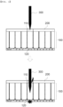
- FIG. 1 is a partial vertical sectional view of a battery module showing a conventional battery cell penetration test.
- a plurality of cylindrical battery cells 100 is mounted in a module case 200 in a state of being disposed so as to be brought into tight contact with each other.
- the cylindrical battery cell has a structure in which venting occurs in a direction toward a cap assembly, and the cylindrical battery cell penetration test is performed using a method of boring a bottom 110 of one of the battery cells using a penetration test apparatus.
- Patent Document 1 which relates to a nail for secondary battery penetration testing and a secondary battery penetration test apparatus using the same, discloses a method of disposing a pouch-shaped battery cell on a holding table and moving the nail in a direction perpendicular to a rectangular plane of the pouch-shaped battery cell so as to be forcibly inserted into a secondary battery. That is, Patent Document 1 also does not disclose a penetration test apparatus capable of penetrating a side of a cylindrical battery cell in the state in which battery cells are assembled into a battery module.
- Patent Document 1 Korean Registered Patent Publication No. 1764299 (2017.07.27 )
- the present invention has been made in view of the above problems, and it is an object of the present invention to provide a side penetration test apparatus for battery cells capable of checking whether, at the time of evaluating safety of battery cells constituting a battery module, flames are transferred to adjacent battery cells, whereby chain ignition occurs, and a battery cell penetration test method using the same.
- a penetration test apparatus to accomplish the above object includes a penetration unit having a needle-shaped conductor formed in a shape of a sharp needle, a guide unit configured to push out the penetration unit such that the needle-shaped conductor bores a side of a battery cell, and a holder configured to receive the penetration unit therein, wherein, when the guide unit pushes the penetration unit, the needle-shaped conductor of the penetration unit penetrates the side of the battery cell.
- the guide unit may be configured to push the penetration unit while moving into the holder.
- a horizontal bar having a length equal to the inner diameter of the holder may be located in the holder, and when the guide unit pushes the penetration unit, the penetration unit may turn about the horizontal bar as the axis of rotation.
- the holder may be provided with an opening, when the penetration unit is pushed by the guide unit, the needle-shaped conductor of the penetration unit may pass through the opening, and an outer tip of the needle-shaped conductor that has passed through the opening may protrude from a surface of the holder.
- the guide unit may include a front portion and a rear portion extending downwards, a space may be formed between the front portion and the rear portion, and the penetration unit may be configured to be inserted into the space in the state in which the guide unit moves into the holder.
- the holder may be configured to have a cylindrical structure, and each of an outer surface of the front portion of the guide unit and an outer surface of the rear portion of the guide unit may be configured to have a curved surface corresponding to a cylindrical inner surface of the holder.
- the penetration unit may include a first surface, into which the needle-shaped conductor is attached, and the first surface may be formed as a plane cut in an oblique direction with respect to an imaginary central axis of the penetration unit.
- An upper part of the penetration unit may be brought into tight contact with an inner surface of the space in a thickness direction.
- An inner surface of the rear portion may be configured to have a flat shape, and an outer surface of the penetration unit opposite a first surface of the penetration unit may include a flat portion brought into tight contact with the inner surface of the rear portion in parallel with the flat portion when the guide unit moves into the holder.
- the present invention provides a battery cell penetration test method using the penetration test apparatus.
- the battery cell penetration test method may include preparing a battery cell stack including a plurality of battery cells, removing one of the plurality of battery cells constituting the battery cell stack and inserting the penetration test apparatus into the position from which the one of the plurality of battery cells has been removed, inserting the guide unit of the penetration test apparatus into the holder, and the needle-shaped conductor of the penetration unit penetrating a side of another one of the plurality of battery cells as the result of being pushed by the guide unit.
- Each of the plurality of battery cells may include a cylindrical battery cell, a pouch-shaped battery cell, or a prismatic battery cell.
- the tip of the needle-shaped conductor of the penetration test apparatus may be disposed so as to face the side of the another one of the plurality of battery cells.
- the present invention may provide various combinations of the above solving means.
- a side penetration test apparatus for battery cells is capable of boring a side of a battery cell in the state in which battery cells are mounted in a battery module case.
- a penetration safety test may be performed under severer conditions than a conventional battery cell penetration test, as described above, whereby it is possible to provide a battery cell with improved safety.
- FIG. 2 is a perspective view of a battery cell penetration test apparatus according to the present invention.
- the battery cell penetration test apparatus 300 includes a penetration unit 310 having a needle-shaped conductor 311 formed in the shape of a sharp needle, a guide unit 320 configured to push out the penetration unit 310 such that the needle-shaped conductor 311 bores a side of a battery cell, and a holder 330 configured to receive the penetration unit 310 therein.
- the guide unit 320 may be located outside the holder 330, or at least a part of the guide unit may be inserted into the holder 330.
- the guide unit pushes the penetration unit 310 in a direction toward the battery cell while moving into the holder 330, whereby the needle-shaped conductor 311 of the penetration unit 310 penetrates the side of the battery cell, and therefore internal short circuit of the battery cell may be artificially induced.
- a horizontal bar 332 having a length equal to the inner diameter of the holder 330 is located in the holder, and the horizontal bar 332 is disposed so as to extend through an upper part of the penetration unit 310.
- the penetration unit 310 may turn forwards about the horizontal bar 332 as the axis of rotation.
- the holder 330 is configured to have a cylindrical structure
- the guide unit 320 includes a front portion 321 and a rear portion 322 extending downwards.
- each of an outer surface 326 of the front portion 321 of the guide unit 320 and an outer surface 327 of the rear portion 322 of the guide unit is configured to have a curved surface corresponding to the cylindrical inner surface of the holder 330.
- the holder having the cylindrical structure has an external appearance similar to the external appearance of a cylindrical battery cell such that, in the state in which a plurality of cylindrical battery cells is mounted in a battery module, any one of the cylindrical battery cells is removed and the penetration test apparatus is inserted into the position from which the cylindrical battery cell has been removed in order to perform a penetration test.
- Battery cells to which the battery cell penetration test apparatus according to the present invention is applicable may include a cylindrical battery cell, a pouch-shaped battery cell, and a prismatic battery cell.
- a battery cell on which a penetration test is to be performed is a prismatic battery cell or a pouch-shaped battery cell, therefore, the shape of the holder may be changed so as to be similar to the external appearance of the prismatic battery cell or the external appearance of the pouch-shaped battery cell.
- the outer diameter of the holder may be formed so as to correspond to the thickness of the prismatic battery cell or the pouch-shaped battery cell.
- a recess 325 is formed in a central part of an inner surface 324 of the rear portion 322, and a protrusion 315 is formed on an outer surface 314 of the penetration unit 310 opposite a first surface 312 thereof.
- the recess 325 may move downwards while sliding in a state of being coupled to the protrusion 315. Consequently, it is possible to prevent deviation in direction of the guide unit 320 that moves downwards.
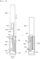
- FIG. 3 is a vertical sectional view showing the operation state of the battery cell penetration test apparatus of FIG. 2 .
- the penetration unit 310 includes a first surface 312, into which the needle-shaped conductor 311 is attached, and the first surface 312 is formed as a plane cut in an oblique direction with respect to an imaginary central axis CA of the penetration unit 310.
- An opening 331 is formed in the side surface of the holder 330 that faces a sharp tip of the needle-shaped conductor 311 of the penetration unit 310.
- the entirety of the needle-shaped conductor 311 is located in the holder 330 in the state in which the guide unit 320 does not push the penetration unit 310, and the outer tip of the needle-shaped conductor 311 that has passed through the opening 331 protrudes from a surface of the holder 330 in the state in which the guide unit 320 completely pushes out the penetration unit 310.
- a catching projection 313 may be added to a lower end of the penetration unit 310.
- a space 323 is formed between the front portion 321 and the rear portion 322, and the penetration unit 310 is inserted into the space 323 in the state in which the guide unit 320 moves into the holder 330.
- an upper part of the penetration unit 310 is brought into tight contact with an inner surface of the space 323 in a thickness direction A.
- an inner surface of the front portion 321 is brought into tight contact with the first surface 312 of the penetration unit 310 in a state of facing the first surface in parallel therewith, and the inner surface 324 of the rear portion 322 is brought into tight contact with the outer surface 314 opposite the first surface in a state of facing the outer surface in parallel therewith.
- the inner surface 324 of the rear portion 322 is configured to have a flat shape
- the outer surface 314 of the penetration unit 310 opposite the first surface 312 includes a flat portion brought into tight contact with the inner surface 324 of the rear portion 322 in parallel therewith when the guide unit 310 moves into the holder 330.
- FIG. 4 is a partial vertical sectional view of a battery module showing a battery cell penetration test using the battery cell penetration test apparatus according to the present invention.
- a battery cell penetration test method includes a step of preparing a battery cell stack including a plurality of battery cells 100, a step of removing one of the battery cells 100 constituting the battery cell stack and inserting the penetration test apparatus 300 into the position from which the battery cell has been removed, a step of inserting the guide unit 320 of the penetration test apparatus 300 into the holder 330, and a step of the needle-shaped conductor 311 of the penetration unit 310 penetrating a side of one of the battery cells 100 as the result of being pushed by the guide unit 320.
- the battery cell stack including the plurality of battery cells 100 is disposed in a module case 200.
- the battery cells 100 shown in FIG. 4 are cylindrical battery cells, the battery cell penetration test using the penetration test apparatus according to the present invention may also be performed for a battery module including prismatic battery cells or pouch-shaped battery cells instead of the cylindrical battery cells.
- the tip of the needle-shaped conductor 311 of the penetration test apparatus 300 is disposed so as to face a side of one of the battery cells 100.
- the needle-shaped conductor 311 bores the side of the battery cell 100.
- the penetration test apparatus When the penetration test apparatus according to the present invention is used, as described above, it is possible to bore the side of one of plurality of the battery cells even in the state in which the plurality of battery cells is disposed in the module case, and therefore it is possible to verify whether chain ignition of adjacent battery cells occurs.
Landscapes
- Chemical & Material Sciences (AREA)
- Engineering & Computer Science (AREA)
- Chemical Kinetics & Catalysis (AREA)
- Electrochemistry (AREA)
- General Chemical & Material Sciences (AREA)
- Manufacturing & Machinery (AREA)
- Life Sciences & Earth Sciences (AREA)
- Health & Medical Sciences (AREA)
- Physics & Mathematics (AREA)
- Analytical Chemistry (AREA)
- Biochemistry (AREA)
- General Health & Medical Sciences (AREA)
- General Physics & Mathematics (AREA)
- Immunology (AREA)
- Pathology (AREA)
- Mechanical Engineering (AREA)
- Battery Mounting, Suspending (AREA)
- Secondary Cells (AREA)
Abstract
Description
- This application claims the benefit of priority to
Korean Patent Application No. 2021-0153612 filed on November 10, 2021 - The present invention relates to a side penetration test apparatus for battery cells and a battery cell penetration test method using the same. More particularly, the present invention relates to a side penetration test apparatus for battery cells configured to perform safety evaluation under severer conditions than a penetration test of boring a bottom of a battery cell and a battery cell penetration test method using the same.
- A secondary battery, which is capable of being charged and discharged, has been used as an energy source for mobile devices. In recent years, the secondary battery has also been used as an energy source for devices that require large capacity and high output, such as an electric vehicle.
- In order to manufacture such as large-capacity, high-output secondary battery, the size of a battery pack is also increased. Provision of a fire protection structure to a secondary battery is important in securing safety of the secondary battery due to the characteristics of the secondary battery, fire of which is not extinguished until the secondary battery is completely combusted when fire breaks out in the secondary battery.
- For example, when external impact is applied to the secondary battery or a sharp electrically conductive member penetrates a case of the secondary battery, electrode plates having different polarities constituting an electrode assembly may be electrically connected to each other via the electrically conductive member, whereby a short circuit may be formed. When great short-circuit current flows between the electrode plates as the result thereof, the temperature of the electrode plates increases, and therefore the temperature of an electrolyte increases. The high-temperature electrolyte is rapidly decomposed and generates a large amount of gas. Since decomposition of the electrolyte is an exothermic reaction, the temperature of the secondary battery locally abruptly increases around the penetrated point, which may eventually cause fire outbreak and thermal runaway of the secondary battery.
- In a development stage before commercialization of the secondary battery, therefore, a battery cell penetration test is performed to verify safety of the secondary battery when the secondary battery is penetrated.
- In general, the battery cell penetration test is performed using a method of penetrating the secondary using a needle-shaped conductor to intentionally induce short circuit in the secondary battery, measuring a change in temperature or voltage of the secondary battery and checking whether fire breaks out in the secondary battery with the naked eye.
- In connection therewith,
FIG. 1 is a partial vertical sectional view of a battery module showing a conventional battery cell penetration test. - Referring to
FIG. 1 , a plurality ofcylindrical battery cells 100 is mounted in amodule case 200 in a state of being disposed so as to be brought into tight contact with each other. The cylindrical battery cell has a structure in which venting occurs in a direction toward a cap assembly, and the cylindrical battery cell penetration test is performed using a method of boring abottom 110 of one of the battery cells using a penetration test apparatus. - When the penetration test apparatus bores the
bottom 110 of the battery cell, as described above, flames are sprayed to anupper part 120 of the battery cell. As a result, transfer of the flames to battery cells adjacent to the bored battery cell or chain ignition of the battery cells is difficult. - Meanwhile, it is necessary to perform the battery cell penetration test under severer conditions in order to further raise safety standards of the secondary battery. For example, when a side of a cylindrical battery cell is bored, explosive power may also be transmitted to a battery cell adjacent to the bored battery cell.
- When the penetration test apparatus shown in
FIG. 1 is used, it is possible to bore the bottom of the cylindrical battery cell or to bore the side of the cylindrical battery cell in the state in which a battery module is not assembled; however, it is difficult to bore the side of the cylindrical battery cell in the state in which the battery module is assembled. - Patent Document 1, which relates to a nail for secondary battery penetration testing and a secondary battery penetration test apparatus using the same, discloses a method of disposing a pouch-shaped battery cell on a holding table and moving the nail in a direction perpendicular to a rectangular plane of the pouch-shaped battery cell so as to be forcibly inserted into a secondary battery. That is, Patent Document 1 also does not disclose a penetration test apparatus capable of penetrating a side of a cylindrical battery cell in the state in which battery cells are assembled into a battery module.
- Therefore, there is a need to develop a penetration test apparatus capable of performing a battery cell penetration test under severe conditions in order to manufacture a secondary battery with further improved safety and penetrating a side of a cylindrical battery cell in the state in which a battery module is assembled.
- (Patent Document 1)
Korean Registered Patent Publication No. 1764299 (2017.07.27 - The present invention has been made in view of the above problems, and it is an object of the present invention to provide a side penetration test apparatus for battery cells capable of checking whether, at the time of evaluating safety of battery cells constituting a battery module, flames are transferred to adjacent battery cells, whereby chain ignition occurs, and a battery cell penetration test method using the same.
- A penetration test apparatus according to the present invention to accomplish the above object includes a penetration unit having a needle-shaped conductor formed in a shape of a sharp needle, a guide unit configured to push out the penetration unit such that the needle-shaped conductor bores a side of a battery cell, and a holder configured to receive the penetration unit therein, wherein, when the guide unit pushes the penetration unit, the needle-shaped conductor of the penetration unit penetrates the side of the battery cell.
- The guide unit may be configured to push the penetration unit while moving into the holder.
- A horizontal bar having a length equal to the inner diameter of the holder may be located in the holder, and when the guide unit pushes the penetration unit, the penetration unit may turn about the horizontal bar as the axis of rotation.
- The holder may be provided with an opening, when the penetration unit is pushed by the guide unit, the needle-shaped conductor of the penetration unit may pass through the opening, and an outer tip of the needle-shaped conductor that has passed through the opening may protrude from a surface of the holder.
- The guide unit may include a front portion and a rear portion extending downwards, a space may be formed between the front portion and the rear portion, and the penetration unit may be configured to be inserted into the space in the state in which the guide unit moves into the holder.
- The holder may be configured to have a cylindrical structure, and each of an outer surface of the front portion of the guide unit and an outer surface of the rear portion of the guide unit may be configured to have a curved surface corresponding to a cylindrical inner surface of the holder.
- The penetration unit may include a first surface, into which the needle-shaped conductor is attached, and the first surface may be formed as a plane cut in an oblique direction with respect to an imaginary central axis of the penetration unit.
- An upper part of the penetration unit may be brought into tight contact with an inner surface of the space in a thickness direction.
- An inner surface of the rear portion may be configured to have a flat shape, and an outer surface of the penetration unit opposite a first surface of the penetration unit may include a flat portion brought into tight contact with the inner surface of the rear portion in parallel with the flat portion when the guide unit moves into the holder.
- The present invention provides a battery cell penetration test method using the penetration test apparatus. Specifically, the battery cell penetration test method may include preparing a battery cell stack including a plurality of battery cells, removing one of the plurality of battery cells constituting the battery cell stack and inserting the penetration test apparatus into the position from which the one of the plurality of battery cells has been removed, inserting the guide unit of the penetration test apparatus into the holder, and the needle-shaped conductor of the penetration unit penetrating a side of another one of the plurality of battery cells as the result of being pushed by the guide unit.
- Each of the plurality of battery cells may include a cylindrical battery cell, a pouch-shaped battery cell, or a prismatic battery cell.
- The tip of the needle-shaped conductor of the penetration test apparatus may be disposed so as to face the side of the another one of the plurality of battery cells.
- In addition, the present invention may provide various combinations of the above solving means.
- As is apparent from the above description, a side penetration test apparatus for battery cells according to the present invention is capable of boring a side of a battery cell in the state in which battery cells are mounted in a battery module case.
- Consequently, it is possible to check whether, when any one of the plurality of battery cells arranged in tight contact with each other is bored, explosive power of the bored battery cell is transferred to battery cells adjacent thereto, whereby chain ignition occurs.
- A penetration safety test may be performed under severer conditions than a conventional battery cell penetration test, as described above, whereby it is possible to provide a battery cell with improved safety.
- In addition, it is possible to perform additional safety verification on side penetration for a battery cell with verified safety on penetration into a bottom of the battery cell.
-
-
FIG. 1 is a partial vertical sectional view of a battery module showing a conventional battery cell penetration test. -
FIG. 2 is a perspective view of a battery cell penetration test apparatus according to the present invention. -
FIG. 3 is a vertical sectional view showing the operation state of the battery cell penetration test apparatus ofFIG. 2 . -
FIG. 4 is a partial vertical sectional view of a battery module showing a battery cell penetration test using the battery cell penetration test apparatus according to the present invention. - Now, preferred embodiments of the present invention will be described in detail with reference to the accompanying drawings such that the preferred embodiments of the present invention can be easily implemented by a person having ordinary skill in the art to which the present invention pertains. In describing the principle of operation of the preferred embodiments of the present invention in detail, however, a detailed description of known functions and configurations incorporated herein will be omitted when the same may obscure the subject matter of the present invention.
- In addition, the same reference numbers will be used throughout the drawings to refer to parts that perform similar functions or operations. In the case in which one part is said to be connected to another part throughout the specification, not only may the one part be directly connected to the other part, but also, the one part may be indirectly connected to the other part via a further part. In addition, that a certain element is included does not mean that other elements are excluded, but means that such elements may be further included unless mentioned otherwise.
- In addition, a description to embody elements through limitation or addition may be applied to all inventions, unless particularly restricted, and does not limit a specific invention.
- Also, in the description of the invention and the claims of the present application, singular forms are intended to include plural forms unless mentioned otherwise.
- Also, in the description of the invention and the claims of the present application, "or" includes "and" unless mentioned otherwise. Therefore, "including A or B" means three cases, namely, the case including A, the case including B, and the case including A and B.
- Hereinafter, embodiments of the present invention will be described in detail with reference to the accompanying drawings.
-
FIG. 2 is a perspective view of a battery cell penetration test apparatus according to the present invention. - Referring to
FIG. 2 , the battery cellpenetration test apparatus 300 according to the present invention includes apenetration unit 310 having a needle-shapedconductor 311 formed in the shape of a sharp needle, aguide unit 320 configured to push out thepenetration unit 310 such that the needle-shapedconductor 311 bores a side of a battery cell, and aholder 330 configured to receive thepenetration unit 310 therein. - The
guide unit 320 may be located outside theholder 330, or at least a part of the guide unit may be inserted into theholder 330. When theguide unit 320 moves downwards, the guide unit pushes thepenetration unit 310 in a direction toward the battery cell while moving into theholder 330, whereby the needle-shapedconductor 311 of thepenetration unit 310 penetrates the side of the battery cell, and therefore internal short circuit of the battery cell may be artificially induced. - A
horizontal bar 332 having a length equal to the inner diameter of theholder 330 is located in the holder, and thehorizontal bar 332 is disposed so as to extend through an upper part of thepenetration unit 310. When theguide unit 320 pushes thepenetration unit 310 from the rear thereof, therefore, thepenetration unit 310 may turn forwards about thehorizontal bar 332 as the axis of rotation. - In the
penetration test apparatus 300 shown inFIG. 2 , theholder 330 is configured to have a cylindrical structure, and theguide unit 320 includes afront portion 321 and arear portion 322 extending downwards. In order to achieve an effect in which thepenetration unit 310 is pushed as thefront portion 321 and therear portion 322 are inserted into theholder 330 along an inner surface of theholder 330, each of anouter surface 326 of thefront portion 321 of theguide unit 320 and anouter surface 327 of therear portion 322 of the guide unit is configured to have a curved surface corresponding to the cylindrical inner surface of theholder 330. - The holder having the cylindrical structure has an external appearance similar to the external appearance of a cylindrical battery cell such that, in the state in which a plurality of cylindrical battery cells is mounted in a battery module, any one of the cylindrical battery cells is removed and the penetration test apparatus is inserted into the position from which the cylindrical battery cell has been removed in order to perform a penetration test.
- Battery cells to which the battery cell penetration test apparatus according to the present invention is applicable may include a cylindrical battery cell, a pouch-shaped battery cell, and a prismatic battery cell. When a battery cell on which a penetration test is to be performed is a prismatic battery cell or a pouch-shaped battery cell, therefore, the shape of the holder may be changed so as to be similar to the external appearance of the prismatic battery cell or the external appearance of the pouch-shaped battery cell. Alternatively, in the penetration test apparatus shown in
FIG. 2 , the outer diameter of the holder may be formed so as to correspond to the thickness of the prismatic battery cell or the pouch-shaped battery cell. - In a concrete example, a
recess 325 is formed in a central part of aninner surface 324 of therear portion 322, and aprotrusion 315 is formed on anouter surface 314 of thepenetration unit 310 opposite afirst surface 312 thereof. When theguide unit 320 moves into theholder 330, therecess 325 may move downwards while sliding in a state of being coupled to theprotrusion 315. Consequently, it is possible to prevent deviation in direction of theguide unit 320 that moves downwards. -
FIG. 3 is a vertical sectional view showing the operation state of the battery cell penetration test apparatus ofFIG. 2 . - Referring to
FIG. 3 , thepenetration unit 310 includes afirst surface 312, into which the needle-shapedconductor 311 is attached, and thefirst surface 312 is formed as a plane cut in an oblique direction with respect to an imaginary central axis CA of thepenetration unit 310. - An
opening 331 is formed in the side surface of theholder 330 that faces a sharp tip of the needle-shapedconductor 311 of thepenetration unit 310. When theguide unit 320 pushes thepenetration unit 310, therefore, thepenetration unit 310 is turned in a clockwise direction, whereby the needle-shapedconductor 311 of thepenetration unit 310 passes through theopening 331. - That is, the entirety of the needle-shaped
conductor 311 is located in theholder 330 in the state in which theguide unit 320 does not push thepenetration unit 310, and the outer tip of the needle-shapedconductor 311 that has passed through theopening 331 protrudes from a surface of theholder 330 in the state in which theguide unit 320 completely pushes out thepenetration unit 310. - At this time, in order to prevent the needle-shaped
conductor 311 from excessively protruding to such an extent that the needle-shaped conductor penetrates another battery cell, a catchingprojection 313 may be added to a lower end of thepenetration unit 310. - A
space 323 is formed between thefront portion 321 and therear portion 322, and thepenetration unit 310 is inserted into thespace 323 in the state in which theguide unit 320 moves into theholder 330. - Specifically, an upper part of the
penetration unit 310 is brought into tight contact with an inner surface of thespace 323 in a thickness direction A. When theguide unit 320 is inserted into theholder 330, an inner surface of thefront portion 321 is brought into tight contact with thefirst surface 312 of thepenetration unit 310 in a state of facing the first surface in parallel therewith, and theinner surface 324 of therear portion 322 is brought into tight contact with theouter surface 314 opposite the first surface in a state of facing the outer surface in parallel therewith. - In a concrete example, the
inner surface 324 of therear portion 322 is configured to have a flat shape, and theouter surface 314 of thepenetration unit 310 opposite thefirst surface 312 includes a flat portion brought into tight contact with theinner surface 324 of therear portion 322 in parallel therewith when theguide unit 310 moves into theholder 330. - Consequently, the flat portion of the
rear portion 322 and the flat portion provided at theouter surface 314 opposite the first surface are brought into tight contact with each other in parallel with each other, whereby thepenetration unit 310 is pushed in the clockwise direction. -
FIG. 4 is a partial vertical sectional view of a battery module showing a battery cell penetration test using the battery cell penetration test apparatus according to the present invention. - A battery cell penetration test method according to the present invention includes a step of preparing a battery cell stack including a plurality of
battery cells 100, a step of removing one of thebattery cells 100 constituting the battery cell stack and inserting thepenetration test apparatus 300 into the position from which the battery cell has been removed, a step of inserting theguide unit 320 of thepenetration test apparatus 300 into theholder 330, and a step of the needle-shapedconductor 311 of thepenetration unit 310 penetrating a side of one of thebattery cells 100 as the result of being pushed by theguide unit 320. - Referring to
FIG. 4 , the battery cell stack including the plurality ofbattery cells 100 is disposed in amodule case 200. Although thebattery cells 100 shown inFIG. 4 are cylindrical battery cells, the battery cell penetration test using the penetration test apparatus according to the present invention may also be performed for a battery module including prismatic battery cells or pouch-shaped battery cells instead of the cylindrical battery cells. - The tip of the needle-shaped
conductor 311 of thepenetration test apparatus 300 is disposed so as to face a side of one of thebattery cells 100. When theguide unit 320 pushes out thepenetration unit 310, therefore, the needle-shapedconductor 311 bores the side of thebattery cell 100. - When the penetration test apparatus according to the present invention is used, as described above, it is possible to bore the side of one of plurality of the battery cells even in the state in which the plurality of battery cells is disposed in the module case, and therefore it is possible to verify whether chain ignition of adjacent battery cells occurs.
- When the battery cell penetration test method is performed using the penetration test apparatus according to the present invention, therefore, it is possible to provide battery cells with improved safety.
- Those skilled in the art to which the present invention pertains will appreciate that various applications and modifications are possible within the category of the present invention based on the above description.
-
- 100: Battery cell
- 110: Bottom of battery cell
- 120: Upper part of battery cell
- 200: Module case
- 300: Penetration test apparatus
- 310: Penetration unit
- 311: Needle-shaped conductor
- 312: First surface
- 313: Catching projection
- 314: Outer surface opposite first surface
- 315: Protrusion
- 320: Guide unit
- 321: Front portion
- 322: Rear portion
- 323: Space
- 324: Inner surface
- 325: Recess
- 326: Outer surface of front portion
- 327: Outer surface of rear portion
- 330: Holder
- 331: Opening
- 332: Horizontal bar
- CA: Central axis
Claims (12)
- A penetration test apparatus comprising:a penetration unit having a needle-shaped conductor formed in a shape of a sharp needle;a guide unit configured to push out the penetration unit such that the needle-shaped conductor bores a side of a battery cell; anda holder configured to receive the penetration unit therein,wherein when the guide unit pushes the penetration unit, the needle-shaped conductor of the penetration unit penetrates the side of the battery cell.
- The penetration test apparatus according to claim 1, wherein the guide unit is configured to push the penetration unit while moving into the holder.
- The penetration test apparatus according to claim 1, whereina horizontal bar having a length equal to an inner diameter of the holder is located in the holder, andwhen the guide unit pushes the penetration unit, the penetration unit turns about the horizontal bar as an axis of rotation.
- The penetration test apparatus according to claim 2, whereinthe holder is provided with an opening,when the penetration unit is pushed by the guide unit, the needle-shaped conductor of the penetration unit passes through the opening, andan outer tip of the needle-shaped conductor that has passed through the opening protrudes from a surface of the holder.
- The penetration test apparatus according to claim 1, whereinthe guide unit comprises a front portion and a rear portion extending downwards,a space is formed between the front portion and the rear portion, andthe penetration unit is configured to be inserted into the space in a state in which the guide unit moves into the holder.
- The penetration test apparatus according to claim 5, whereinthe holder is configured to have a cylindrical structure, andeach of an outer surface of the front portion of the guide unit and an outer surface of the rear portion of the guide unit is configured to have a curved surface corresponding to a cylindrical inner surface of the holder.
- The penetration test apparatus according to claim 1, whereinthe penetration unit comprises a first surface, into which the needle-shaped conductor is attached, andthe first surface is formed as a plane cut in an oblique direction with respect to an imaginary central axis of the penetration unit.
- The penetration test apparatus according to claim 5, wherein an upper part of the penetration unit is brought into tight contact with an inner surface of the space in a thickness direction.
- The penetration test apparatus according to claim 5, whereinan inner surface of the rear portion is configured to have a flat shape, andan outer surface of the penetration unit opposite a first surface of the penetration unit comprises a flat portion brought into tight contact with the inner surface of the rear portion in parallel with the flat portion when the guide unit moves into the holder.
- A battery cell penetration test method using the penetration test apparatus according to any one of claims 1 to 9, the battery cell penetration test method comprising:preparing a battery cell stack comprising a plurality of battery cells;removing one of the plurality of battery cells constituting the battery cell stack and inserting the penetration test apparatus into a position from which the one of the plurality of battery cells has been removed;inserting the guide unit of the penetration test apparatus into the holder; andthe needle-shaped conductor of the penetration unit penetrating a side of another one of the plurality of battery cells as a result of being pushed by the guide unit.
- The battery cell penetration test method according to claim 10, wherein each of the plurality of battery cells comprises a cylindrical battery cell, a pouch-shaped battery cell, or a prismatic battery cell.
- The battery cell penetration test method according to claim 10, wherein a tip of the needle-shaped conductor of the penetration test apparatus is disposed so as to face the side of the another one of the plurality of battery cells.
Applications Claiming Priority (2)
| Application Number | Priority Date | Filing Date | Title |
|---|---|---|---|
| KR1020210153612A KR102951385B1 (en) | 2021-11-10 | 2021-11-10 | Battery Cell Side Penetration Test Apparatus and Battery Cell Penetration Test Method Using the Same |
| PCT/KR2022/017546 WO2023085768A1 (en) | 2021-11-10 | 2022-11-09 | Battery cell side penetration test device and battery cell penetration test method using same |
Publications (2)
| Publication Number | Publication Date |
|---|---|
| EP4318729A1 true EP4318729A1 (en) | 2024-02-07 |
| EP4318729A4 EP4318729A4 (en) | 2024-10-30 |
Family
ID=86336236
Family Applications (1)
| Application Number | Title | Priority Date | Filing Date |
|---|---|---|---|
| EP22893188.7A Pending EP4318729A4 (en) | 2021-11-10 | 2022-11-09 | BATTERY CELL SIDE PENETRATION TESTING DEVICE AND CORRESPONDING BATTERY CELL PENETRATION TESTING METHOD |
Country Status (6)
| Country | Link |
|---|---|
| US (1) | US12431548B2 (en) |
| EP (1) | EP4318729A4 (en) |
| JP (1) | JP7655583B2 (en) |
| KR (1) | KR102951385B1 (en) |
| CN (1) | CN117242620A (en) |
| WO (1) | WO2023085768A1 (en) |
Families Citing this family (1)
| Publication number | Priority date | Publication date | Assignee | Title |
|---|---|---|---|---|
| KR20250064208A (en) * | 2023-11-02 | 2025-05-09 | 주식회사 엘지에너지솔루션 | Thermal propagation test jig for battery |
Family Cites Families (26)
| Publication number | Priority date | Publication date | Assignee | Title |
|---|---|---|---|---|
| KR100874980B1 (en) | 2007-10-09 | 2008-12-19 | 한국단자공업 주식회사 | Spring part forming device of two-row progressive mold |
| JP5223329B2 (en) | 2007-12-26 | 2013-06-26 | Tdk株式会社 | Electrochemical element evaluation method and electrochemical element evaluation apparatus |
| US8193771B2 (en) | 2008-05-22 | 2012-06-05 | Nuwave Technologies, Inc. | Battery tester |
| CN201945527U (en) | 2010-12-17 | 2011-08-24 | 林海珍 | A New Horizontal Battery Acupuncture Testing Machine |
| KR20130043478A (en) * | 2011-10-20 | 2013-04-30 | 주식회사 엘지화학 | Apparatus and method for penetration test of battery |
| JP5989590B2 (en) * | 2012-07-11 | 2016-09-07 | 株式会社日本自動車部品総合研究所 | Puncture strength measuring device |
| KR200477892Y1 (en) | 2013-05-03 | 2015-08-03 | 배옥선 | Fold hotchkiss |
| JP2015072266A (en) | 2013-09-05 | 2015-04-16 | 株式会社山本金属製作所 | Safety testing method and device therefor |
| KR101590956B1 (en) | 2013-11-12 | 2016-02-18 | 유한회사 듀오콤 | Battery nail tester and Battery nail test method |
| US9495493B2 (en) | 2013-11-25 | 2016-11-15 | Lg Chem, Ltd. | Overcurrent simulation method when nail penetrates secondary battery and recording medium storing the program |
| KR101549177B1 (en) | 2013-11-25 | 2015-09-02 | 주식회사 엘지화학 | Simulation method of over current when nail penetrates the secondary battery and storing medium recording thereof |
| JP6063884B2 (en) * | 2014-02-24 | 2017-01-18 | エスペック株式会社 | Battery testing device |
| JP2016004722A (en) | 2014-06-18 | 2016-01-12 | 三菱自動車工業株式会社 | Short circuit test device for secondary battery |
| KR101744120B1 (en) | 2014-08-11 | 2017-06-07 | 주식회사 엘지화학 | Pouch-typed Secondary Battery of Improved Safety of Nail Penetration Test |
| KR101777903B1 (en) * | 2014-09-04 | 2017-09-12 | 주식회사 엘지화학 | Apparatus And Method For Penetration Test Of Secondary Battery |
| KR101764299B1 (en) | 2015-05-06 | 2017-08-03 | 주식회사 엘지화학 | Nail for penetration test of secondary battery and secondary battery penetration test device using thereof |
| KR101927257B1 (en) * | 2015-09-09 | 2018-12-10 | 주식회사 엘지화학 | Apparatus of Testing Secondary Battery by Nail Penetration and Method thereof |
| CN109690827A (en) * | 2016-09-22 | 2019-04-26 | 苹果公司 | Current collector for stacked cell design |
| JP6900716B2 (en) | 2017-03-14 | 2021-07-07 | 日本電気株式会社 | Battery internal short circuit test method and internal short circuit test equipment |
| JP6729481B2 (en) * | 2017-04-28 | 2020-07-22 | トヨタ自動車株式会社 | Laminated battery |
| JP2019140079A (en) | 2018-02-06 | 2019-08-22 | トヨタ自動車株式会社 | Stacked battery |
| CN113678301B (en) * | 2019-04-10 | 2024-07-12 | 本田技研工业株式会社 | Battery evaluation method and battery evaluation device |
| CN111836314A (en) | 2019-04-22 | 2020-10-27 | 索尼公司 | Centralized unit equipment, user equipment, wireless communication method and storage medium |
| KR20210090477A (en) | 2020-01-10 | 2021-07-20 | 에스케이이노베이션 주식회사 | Battery module with improved stability |
| DE102021104098A1 (en) | 2021-02-22 | 2022-08-25 | Iav Gmbh Ingenieurgesellschaft Auto Und Verkehr | Propagation test cell for secondary electric battery cells and cell modules |
| US20230402601A1 (en) * | 2022-06-08 | 2023-12-14 | Semiconductor Energy Laboratory Co., Ltd. | Battery |
-
2021
- 2021-11-10 KR KR1020210153612A patent/KR102951385B1/en active Active
-
2022
- 2022-11-09 CN CN202280032380.XA patent/CN117242620A/en active Pending
- 2022-11-09 JP JP2023552559A patent/JP7655583B2/en active Active
- 2022-11-09 US US18/280,555 patent/US12431548B2/en active Active
- 2022-11-09 EP EP22893188.7A patent/EP4318729A4/en active Pending
- 2022-11-09 WO PCT/KR2022/017546 patent/WO2023085768A1/en not_active Ceased
Also Published As
| Publication number | Publication date |
|---|---|
| JP2024509131A (en) | 2024-02-29 |
| KR102951385B1 (en) | 2026-04-10 |
| CN117242620A (en) | 2023-12-15 |
| KR20230067893A (en) | 2023-05-17 |
| US20240154190A1 (en) | 2024-05-09 |
| EP4318729A4 (en) | 2024-10-30 |
| WO2023085768A1 (en) | 2023-05-19 |
| US12431548B2 (en) | 2025-09-30 |
| JP7655583B2 (en) | 2025-04-02 |
Similar Documents
| Publication | Publication Date | Title |
|---|---|---|
| US12451529B2 (en) | Battery module for detecting swelling phenomenon thereof | |
| JP4373269B2 (en) | Winding electrode assembly and secondary battery equipped with the same | |
| KR101201748B1 (en) | Battery modual | |
| EP3306701A1 (en) | Battery module having structure wherein terminal plates and bms are directly connected | |
| KR20230006265A (en) | Apparatus and Method for Indentation Test of Secondary Battery | |
| KR20100041442A (en) | Battery pack containing electrode terminal connecting device | |
| US11710874B2 (en) | Battery module | |
| US12431548B2 (en) | Side penetration test apparatus for battery cells and battery cell penetration test method using the same | |
| CN103493284A (en) | Battery pack processing device and processing method | |
| KR101389227B1 (en) | Lithium-ion battery for preventing overcharge of battery cell | |
| KR101767347B1 (en) | Cap assembly for secondary battery | |
| KR101777903B1 (en) | Apparatus And Method For Penetration Test Of Secondary Battery | |
| KR20220109173A (en) | Cylindrical battery module for chain ignition prevention | |
| KR20140093077A (en) | Rechargeable battery | |
| US20250174806A1 (en) | Battery module with enhanced flame path and battery pack including same | |
| KR101134400B1 (en) | Connecting Member of Improved Coupling Property | |
| US20230420752A1 (en) | Method for generating smoke in cell pack | |
| CN115395187B (en) | Self-protection system of electric vehicle power battery and electric vehicle power battery | |
| EP4604262A1 (en) | Thermal runaway test jig for batteries | |
| JP7236653B2 (en) | battery unit | |
| KR20150049886A (en) | Jig for welding protection circuit module of battery cell | |
| JP2026022826A (en) | Secondary battery test device and secondary battery test method | |
| KR20240050643A (en) | Jig for charging and discharging of cylindrical battery cell | |
| KR20250037831A (en) | Secondary battery | |
| KR20190072356A (en) | Secondary battery improved penetration characteristi |
Legal Events
| Date | Code | Title | Description |
|---|---|---|---|
| STAA | Information on the status of an ep patent application or granted ep patent |
Free format text: STATUS: THE INTERNATIONAL PUBLICATION HAS BEEN MADE |
|
| PUAI | Public reference made under article 153(3) epc to a published international application that has entered the european phase |
Free format text: ORIGINAL CODE: 0009012 |
|
| STAA | Information on the status of an ep patent application or granted ep patent |
Free format text: STATUS: REQUEST FOR EXAMINATION WAS MADE |
|
| 17P | Request for examination filed |
Effective date: 20231024 |
|
| AK | Designated contracting states |
Kind code of ref document: A1 Designated state(s): AL AT BE BG CH CY CZ DE DK EE ES FI FR GB GR HR HU IE IS IT LI LT LU LV MC ME MK MT NL NO PL PT RO RS SE SI SK SM TR |
|
| TPAC | Observations filed by third parties |
Free format text: ORIGINAL CODE: EPIDOSNTIPA |
|
| A4 | Supplementary search report drawn up and despatched |
Effective date: 20241002 |
|
| RIC1 | Information provided on ipc code assigned before grant |
Ipc: G01N 3/30 20060101ALN20240926BHEP Ipc: H01M 50/213 20210101ALN20240926BHEP Ipc: H01M 50/211 20210101ALN20240926BHEP Ipc: H01M 10/48 20060101ALI20240926BHEP Ipc: H01M 10/42 20060101AFI20240926BHEP |
|
| DAV | Request for validation of the european patent (deleted) | ||
| DAX | Request for extension of the european patent (deleted) | ||
| STAA | Information on the status of an ep patent application or granted ep patent |
Free format text: STATUS: EXAMINATION IS IN PROGRESS |
|
| 17Q | First examination report despatched |
Effective date: 20250807 |
|
| GRAP | Despatch of communication of intention to grant a patent |
Free format text: ORIGINAL CODE: EPIDOSNIGR1 |
|
| STAA | Information on the status of an ep patent application or granted ep patent |
Free format text: STATUS: GRANT OF PATENT IS INTENDED |