EP4318720A1 - Positive electrode plate and battery - Google Patents
Positive electrode plate and battery Download PDFInfo
- Publication number
- EP4318720A1 EP4318720A1 EP22897383.0A EP22897383A EP4318720A1 EP 4318720 A1 EP4318720 A1 EP 4318720A1 EP 22897383 A EP22897383 A EP 22897383A EP 4318720 A1 EP4318720 A1 EP 4318720A1
- Authority
- EP
- European Patent Office
- Prior art keywords
- insulating layer
- cathode
- cathode plate
- faces
- face
- Prior art date
- Legal status (The legal status is an assumption and is not a legal conclusion. Google has not performed a legal analysis and makes no representation as to the accuracy of the status listed.)
- Pending
Links
Images


Classifications
-
- H—ELECTRICITY
- H01—ELECTRIC ELEMENTS
- H01M—PROCESSES OR MEANS, e.g. BATTERIES, FOR THE DIRECT CONVERSION OF CHEMICAL ENERGY INTO ELECTRICAL ENERGY
- H01M10/00—Secondary cells; Manufacture thereof
- H01M10/05—Accumulators with non-aqueous electrolyte
- H01M10/058—Construction or manufacture
- H01M10/0587—Construction or manufacture of accumulators having only wound construction elements, i.e. wound positive electrodes, wound negative electrodes and wound separators
-
- H—ELECTRICITY
- H01—ELECTRIC ELEMENTS
- H01M—PROCESSES OR MEANS, e.g. BATTERIES, FOR THE DIRECT CONVERSION OF CHEMICAL ENERGY INTO ELECTRICAL ENERGY
- H01M10/00—Secondary cells; Manufacture thereof
- H01M10/04—Construction or manufacture in general
- H01M10/0413—Large-sized flat cells or batteries for motive or stationary systems with plate-like electrodes
- H01M10/0418—Large-sized flat cells or batteries for motive or stationary systems with plate-like electrodes with bipolar electrodes
-
- H—ELECTRICITY
- H01—ELECTRIC ELEMENTS
- H01M—PROCESSES OR MEANS, e.g. BATTERIES, FOR THE DIRECT CONVERSION OF CHEMICAL ENERGY INTO ELECTRICAL ENERGY
- H01M10/00—Secondary cells; Manufacture thereof
- H01M10/04—Construction or manufacture in general
- H01M10/0431—Cells with wound or folded electrodes
-
- H—ELECTRICITY
- H01—ELECTRIC ELEMENTS
- H01M—PROCESSES OR MEANS, e.g. BATTERIES, FOR THE DIRECT CONVERSION OF CHEMICAL ENERGY INTO ELECTRICAL ENERGY
- H01M10/00—Secondary cells; Manufacture thereof
- H01M10/04—Construction or manufacture in general
- H01M10/0436—Small-sized flat cells or batteries for portable equipment
- H01M10/044—Small-sized flat cells or batteries for portable equipment with bipolar electrodes
-
- H—ELECTRICITY
- H01—ELECTRIC ELEMENTS
- H01M—PROCESSES OR MEANS, e.g. BATTERIES, FOR THE DIRECT CONVERSION OF CHEMICAL ENERGY INTO ELECTRICAL ENERGY
- H01M10/00—Secondary cells; Manufacture thereof
- H01M10/05—Accumulators with non-aqueous electrolyte
- H01M10/052—Li-accumulators
- H01M10/0525—Rocking-chair batteries, i.e. batteries with lithium insertion or intercalation in both electrodes; Lithium-ion batteries
-
- H—ELECTRICITY
- H01—ELECTRIC ELEMENTS
- H01M—PROCESSES OR MEANS, e.g. BATTERIES, FOR THE DIRECT CONVERSION OF CHEMICAL ENERGY INTO ELECTRICAL ENERGY
- H01M10/00—Secondary cells; Manufacture thereof
- H01M10/05—Accumulators with non-aqueous electrolyte
- H01M10/058—Construction or manufacture
- H01M10/0583—Construction or manufacture of accumulators with folded construction elements except wound ones, i.e. folded positive or negative electrodes or separators, e.g. with "Z"-shaped electrodes or separators
-
- H—ELECTRICITY
- H01—ELECTRIC ELEMENTS
- H01M—PROCESSES OR MEANS, e.g. BATTERIES, FOR THE DIRECT CONVERSION OF CHEMICAL ENERGY INTO ELECTRICAL ENERGY
- H01M10/00—Secondary cells; Manufacture thereof
- H01M10/05—Accumulators with non-aqueous electrolyte
- H01M10/058—Construction or manufacture
- H01M10/0585—Construction or manufacture of accumulators having only flat construction elements, i.e. flat positive electrodes, flat negative electrodes and flat separators
-
- H—ELECTRICITY
- H01—ELECTRIC ELEMENTS
- H01M—PROCESSES OR MEANS, e.g. BATTERIES, FOR THE DIRECT CONVERSION OF CHEMICAL ENERGY INTO ELECTRICAL ENERGY
- H01M10/00—Secondary cells; Manufacture thereof
- H01M10/42—Methods or arrangements for servicing or maintenance of secondary cells or secondary half-cells
- H01M10/4235—Safety or regulating additives or arrangements in electrodes, separators or electrolyte
-
- H—ELECTRICITY
- H01—ELECTRIC ELEMENTS
- H01M—PROCESSES OR MEANS, e.g. BATTERIES, FOR THE DIRECT CONVERSION OF CHEMICAL ENERGY INTO ELECTRICAL ENERGY
- H01M4/00—Electrodes
- H01M4/02—Electrodes composed of, or comprising, active material
- H01M4/13—Electrodes for accumulators with non-aqueous electrolyte, e.g. for lithium-accumulators; Processes of manufacture thereof
-
- H—ELECTRICITY
- H01—ELECTRIC ELEMENTS
- H01M—PROCESSES OR MEANS, e.g. BATTERIES, FOR THE DIRECT CONVERSION OF CHEMICAL ENERGY INTO ELECTRICAL ENERGY
- H01M50/00—Constructional details or processes of manufacture of the non-active parts of electrochemical cells other than fuel cells, e.g. hybrid cells
- H01M50/50—Current conducting connections for cells or batteries
- H01M50/572—Means for preventing undesired use or discharge
- H01M50/584—Means for preventing undesired use or discharge for preventing incorrect connections inside or outside the batteries
- H01M50/586—Means for preventing undesired use or discharge for preventing incorrect connections inside or outside the batteries inside the batteries, e.g. incorrect connections of electrodes
-
- H—ELECTRICITY
- H01—ELECTRIC ELEMENTS
- H01M—PROCESSES OR MEANS, e.g. BATTERIES, FOR THE DIRECT CONVERSION OF CHEMICAL ENERGY INTO ELECTRICAL ENERGY
- H01M50/00—Constructional details or processes of manufacture of the non-active parts of electrochemical cells other than fuel cells, e.g. hybrid cells
- H01M50/50—Current conducting connections for cells or batteries
- H01M50/572—Means for preventing undesired use or discharge
- H01M50/584—Means for preventing undesired use or discharge for preventing incorrect connections inside or outside the batteries
- H01M50/59—Means for preventing undesired use or discharge for preventing incorrect connections inside or outside the batteries characterised by the protection means
-
- H—ELECTRICITY
- H01—ELECTRIC ELEMENTS
- H01M—PROCESSES OR MEANS, e.g. BATTERIES, FOR THE DIRECT CONVERSION OF CHEMICAL ENERGY INTO ELECTRICAL ENERGY
- H01M50/00—Constructional details or processes of manufacture of the non-active parts of electrochemical cells other than fuel cells, e.g. hybrid cells
- H01M50/50—Current conducting connections for cells or batteries
- H01M50/572—Means for preventing undesired use or discharge
- H01M50/584—Means for preventing undesired use or discharge for preventing incorrect connections inside or outside the batteries
- H01M50/59—Means for preventing undesired use or discharge for preventing incorrect connections inside or outside the batteries characterised by the protection means
- H01M50/593—Spacers; Insulating plates
-
- H—ELECTRICITY
- H01—ELECTRIC ELEMENTS
- H01M—PROCESSES OR MEANS, e.g. BATTERIES, FOR THE DIRECT CONVERSION OF CHEMICAL ENERGY INTO ELECTRICAL ENERGY
- H01M4/00—Electrodes
- H01M4/02—Electrodes composed of, or comprising, active material
- H01M2004/026—Electrodes composed of, or comprising, active material characterised by the polarity
- H01M2004/028—Positive electrodes
-
- Y—GENERAL TAGGING OF NEW TECHNOLOGICAL DEVELOPMENTS; GENERAL TAGGING OF CROSS-SECTIONAL TECHNOLOGIES SPANNING OVER SEVERAL SECTIONS OF THE IPC; TECHNICAL SUBJECTS COVERED BY FORMER USPC CROSS-REFERENCE ART COLLECTIONS [XRACs] AND DIGESTS
- Y02—TECHNOLOGIES OR APPLICATIONS FOR MITIGATION OR ADAPTATION AGAINST CLIMATE CHANGE
- Y02E—REDUCTION OF GREENHOUSE GAS [GHG] EMISSIONS, RELATED TO ENERGY GENERATION, TRANSMISSION OR DISTRIBUTION
- Y02E60/00—Enabling technologies; Technologies with a potential or indirect contribution to GHG emissions mitigation
- Y02E60/10—Energy storage using batteries
-
- Y—GENERAL TAGGING OF NEW TECHNOLOGICAL DEVELOPMENTS; GENERAL TAGGING OF CROSS-SECTIONAL TECHNOLOGIES SPANNING OVER SEVERAL SECTIONS OF THE IPC; TECHNICAL SUBJECTS COVERED BY FORMER USPC CROSS-REFERENCE ART COLLECTIONS [XRACs] AND DIGESTS
- Y02—TECHNOLOGIES OR APPLICATIONS FOR MITIGATION OR ADAPTATION AGAINST CLIMATE CHANGE
- Y02P—CLIMATE CHANGE MITIGATION TECHNOLOGIES IN THE PRODUCTION OR PROCESSING OF GOODS
- Y02P70/00—Climate change mitigation technologies in the production process for final industrial or consumer products
- Y02P70/50—Manufacturing or production processes characterised by the final manufactured product
Definitions
- the present application relates to the technical field of batteries, and in particular, to a cathode plate and a battery.
- lithium-ion batteries are widely used in energy storage power systems such as water power, firepower, wind power, and solar power stations, as well as fields like power tools, electric bicycles, electric motorcycles, electric vehicles, military equipment, aerospace, and the like. Due to the great development of lithium-ion batteries, higher requirements have been raised for their safety performance, and so on.
- an objective of the present application provides a cathode plate and a battery, which prevent the short circuit caused by burrs and improve the safety performance.
- the present application provides a cathode plate and a battery.
- a first aspect of the present application provides a cathode plate, which is arranged in a laminated battery, including: a cuboid main body, formed by stacking a cathode active material layer and a cathode current collector in a first direction, the main body having four side faces and two end faces, the two end faces being arranged oppositely to each other in the first direction, and the four side faces being the first side face to the fourth side face and being respectively connected to the two end faces along the first direction; a cathode tab, formed by the cathode current collector extending from the first side face to an outside of the main body; and an insulating layer, formed on the second side face to the fourth side face and covering 95% or more of each side face of the second side face to the fourth side face.
- the electrode plate that can be arranged in the laminated battery of the present application has four side faces, and the four side faces are all cutting surfaces, the cathode tab is located on the first side face, and the insulating layer is provided on the second to the fourth side faces and covers 95% or more of each side face of the second to fourth side faces.
- the insulating layer formed on the second to the fourth side faces can wrap the burrs formed on the second to the fourth side faces, thereby preventing a short circuit caused by the burrs and improving the safety performance of the laminated battery.
- the cathode tab is located on the first side face, the method for forming an insulating layer on the first side is relatively complicated.
- an insulating layer with a coverage of 95% or higher is formed on the second to the fourth side faces respectively, and no insulating layer is formed on the first side face having the cathode tab, which can improve the safety performance of the laminated battery, such that the production efficiency of the laminated battery is improved.
- the insulating layer is also formed on the first side face and covers 95% or more of all other areas of the first side face except an area where the cathode tab is formed.
- the insulating layer is not only formed with a coverage of 95% or more on the second side face to the fourth side face, but also formed with a coverage of 95% or more on all other areas of the first side face except the area where the cathode tab is formed, thus it can wrap the burrs formed on the first side face to the fourth side face, that is, it can wrap the burrs on all cutting surfaces of the cathode plate and further improve the safety performance of the laminated battery.
- the insulating layer extends from the side faces on which the insulating layer is formed to the end faces connected to the side faces, and a length extending on the end faces that are connected to the side face is no more than 0.5 mm.
- the insulating layer formed on the side faces of the cathode plate extends on the end faces connected to the side faces, so the insulating layer can wrap the burrs extending from the side faces to the end faces, preventing the short circuit caused by shrinkage of the separator, etc., and the length of the extension is no more than 0.5 mm, so the insulating layer can prevent the anode plate from being squeezed through the separator due to excessive insulating layers, and further improve the safety performance of the laminated battery.
- a thickness of the insulating layer on the side faces on which the insulating layer is formed is 2 -30 ⁇ m.
- the thickness of the insulating layer on the side faces on which the insulating layer is formed is no less than 2 ⁇ m, which avoids that the insulating layer is too thin to completely cover the burrs when the burrs are long, and the thickness of the insulating layer on the side faces on which the insulating layer is formed is no more than 30 ⁇ m, which avoids the insulating layer from falling off and forming particles due to the insulating layer being too thick, and improves the safety performance of the laminated battery.
- a second aspect of the present application provides a cathode plate, which is arranged in a wound battery, including: a main body capable of being wound into a helical shape around an axial direction, the main body being formed by stacking a cathode active material layer and a cathode current collector, the main body having two main faces, and the two main faces being two opposite faces along a stacking direction of the cathode active material layer and the cathode current collector; a cathode tab, which is formed by the cathode current collector extending from a top face to an outside of the main body along the axial direction, the top face being perpendicular to the axial direction and connected with the two main faces; and an insulating layer, which is formed on a bottom face and covering 95% or more of the bottom face, the bottom face being opposite to the top face in the axial direction and being perpendicular to the axial direction and connected with the two main faces.
- the cathode plate that can be arranged in a wound battery of the present application has a top face, a bottom face, and two main faces, in which the top face and the bottom face are both cutting surfaces, and an insulating layer is arranged on the bottom face covering 95% or more of the bottom face.
- the insulating layer formed on the bottom face can wrap the burrs formed on the bottom face, prevent short circuits caused by the burrs, and improve the safety performance of the wound battery.
- the top face has a cathode tab
- the method of forming an insulating layer on the top face is relatively complicated. Therefore, an insulating layer with a coverage of 95% or more is formed on the bottom face, and no insulating layer is formed on the top face having the cathode tab, which can improve the production efficiency of the wound battery while improving the safety performance thereof.
- the insulating layer extends from the bottom face to the main faces connected to the bottom face, and a length extending on the main faces connected to the bottom face is no greater than 0.5 mm.
- the insulating layer formed on the bottom face of the cathode plate extends on the main faces connected to the bottom face, so the burrs extending from the bottom face to the main faces can be wrapped to prevent short circuits caused by shrinkage of the separator, etc., and the length of the extension is no greater than 0.5 mm, so the insulating layer can be prevented from pressing the anode plate through the separator, and the safety performance of the wound battery can be further improved.
- a thickness of the insulating layer on the bottom face is 2 ⁇ m -30 ⁇ m.
- the thickness of the insulating layer on the bottom face is no less than 2 ⁇ m, which avoids that the insulation layer is too thin to completely cover the burrs when the burrs are long, and the thickness of the insulating layer on the bottom face is no more than 30 ⁇ m, which prevents the insulating layer from falling off to form particles due to the insulating layer being too thick, and improves the safety performance of the wound battery.
- two thinned parts recessed toward the top face are respectively provided on the bottom face in areas connected to the two main faces, and the insulating layer is arranged on the thinned parts.
- the thinned parts recessed toward the top face are respectively formed on the bottom face in the areas close to the two main faces, and the insulating layer is arranged on the thinned parts, so that the insulating layer can be prevented from extending too long on the main faces and squeezing the anode plate through the separator, and the burrs extending from the bottom face to the main faces are wrapped to further improve the safety performance of the laminated battery.
- a sum of thicknesses of the insulating layer in each thinned part and the main body is no greater than a thickness of the main body outside the thinned parts.
- the insulating layer on the thinned parts does not protrude beyond the main faces of the cathode plate, so the insulating layer can be prevented from squeezing the anode plate through the separator, and the safety performance of the laminated battery can be further improved.
- the thinned parts are in a cuboid shape, a thickness along a direction perpendicular to the main faces is 5 ⁇ m or less, and a length along the axial direction is 0.5 -5 mm.
- the thinned parts are formed into a cuboid shape, and the thickness along the direction perpendicular to the main faces is 5 ⁇ m or less, and the length along the axial direction is 0.5 -5 mm, so that the insulating layer can wrap the burrs extending from the bottom face to the main faces without occupying a significant volume of the main body, thereby ensuring that the energy density of the battery is sufficiently high.
- the insulating layer is coated by one of spray coating, spot coating, and dip coating.
- the insulating layer is formed on the cathode plate in advance, the forming of the insulating layer will not be hindered by the structure of the laminated battery or the wound battery, and the insulating layer can be formed by one of spray coating, spot coating, and dip coating, thereby simplifying the manufacturing process.
- a ceramic slurry for making the insulating layer includes at least a ceramic material, a binder, and a solvent, and the ceramic material accounts for 10 - 70wt%, the binder accounts for 1-5wt%, and a viscosity of the ceramic slurry is 100 -1000 mPa ⁇ s.
- the insulating layer is made of the ceramic slurry including at least a ceramic material, a binder, and a solvent, so the insulation and adhesion of the insulating layer can be ensured, and the ceramic material accounts for 10 -70wt%, the binder accounts for 1 -5wt%, and the viscosity of the ceramic slurry is 100 -1000 mPa ⁇ s, which avoids the insufficient insulation due to the ceramic material being little, or the insufficient adhesion that will cause the insulating layer to fall off due to excessive ceramic material.
- the ceramic material is one of pseudoboehmite, magnesium oxide, silicon carbide, and silicon nitride, preferably pseudoboehmite;
- the binder is one or a combination of polyvinylidene fluoride, polyacrylate, methyl acrylate, ethyl acrylate, 2-methyl methacrylate, and 2-ethyl methacrylate, preferably polyvinylidene fluoride;
- the solvent is N-methylpyrrolidone.
- a third aspect of the present application provides a battery, which includes the cathode plate of the above-mentioned first aspect, an anode plate, and a separator, the cathode plate and the anode plate are alternately stacked in the first direction, and the separator is sandwiched between the cathode plate and the anode plate.
- a fourth aspect of the present application provides a battery, which includes the cathode plate of the above-mentioned second aspect, an anode plate, and a separator, the cathode plate, the anode plate, and the separator are wound around the axial direction, and the separator is sandwiched between the cathode plate and the anode plate.
- the advantageous effects of the present application are as follows:
- the present application provides a cathode plate and a battery, which prevent a short circuit caused by burrs and improve the safety performance of the battery.
- Reference numbers in the drawings are as follows: 1 laminated battery; 11 cathode plate; 12 anode plate; 13 separator; 111 cathode current collector; 112 cathode active material layer; 113 insulating layer; 114 cathode tab; 11a, 11b end faces; 11c first side face; 11d second side face; 11e third side face; 11f fourth side face; 2 wound battery; 21 cathode plate; 22 anode plate; 23 separator; 211 cathode current collector; 212 cathode active material layer; 213 insulating layer; 214 cathode tab; 215 thinned part; 21a top face; 21b bottom face; and 21c, 21d main faces.
- ranges disclosed in the application is defined in the form of lower limit and upper limit, and the given range is limited by selecting a lower limit and an upper limit, and the selected lower limit and upper limit define the boundary of a special range. Ranges defined in this manner may be inclusive or exclusive and may be combined arbitrarily, i.e., any lower limit may be combined with any upper limit to form a range. For example, if ranges of 60-120 and 80-110 are listed for a particular parameter, it is understood that ranges of 60-110 and 80-120 are contemplated. Additionally, if the minimum range values 1 and 2 are listed, and if the maximum range values 3, 4, and 5 are listed, the following ranges are all expected: 1-3, 1-4, 1-5, 2- 3, 2-4, and 2-5.
- the numerical range "a-b” represents an abbreviated representation of any combination of real numbers between a and b, where a and b are both real numbers.
- the numerical range "0-5" indicates that all real numbers between "0-5" have been listed in this article, and "0-5" is only an abbreviated representation of the combination of these values.
- a certain parameter is an integer ⁇ 2
- the method including steps (a) and (b) means that the method may include steps (a) and (b) performed in sequence, and may also include steps (b) and (a) performed in sequence.
- the method may also include step (c), means that step (c) may be added to the method in any order, for example, the method may include steps (a), (b) and (c), may also include steps (a), (c) and (b), and may also include steps (c), (a) and (b).
- the term "or” is inclusive.
- the phrase "A or B” means “A, B, or both A and B.” More specifically, the condition "A or B” is satisfied by either: A is true (or exists) and B is false (or does not exist); A is false (or does not exist) and B is true (or exists); or both A and B are true (or exist).
- the electrode plate is formed by a current collector sandwiched by two layers of electrode active materials, or stacking of a layer of electrode active material layer and a current collector, in which the current collector of the cathode plate is composed of a metal foil (usually an aluminum foil), when cutting along the stacking direction, the cathode current collector is prone to produce burrs.
- the burrs may penetrate the separator sandwiched between the cathode plate and the anode plate, causing a short circuit as the burrs contact the cathode plate or the anode plate.
- the cathode plate exceeds the anode plate and lithium is deposited, thus when burrs exist, the burrs are likely to overlap with the lithium dendrite, resulting risk of short-circuit failure. Therefore, the burrs will affect the safety performance of the battery.
- the laminated cathode plate and anode plate have one side wrapped by the separator, the burrs on the one side cannot be completely covered by spray coating, brush coating, spot coating, or dip coating.
- glue is applied to the edges of the wound cathode plate, separator, and anode plate to reduce the probability of burrs on the cutting edge, however, the separator is longer than the anode plate and the anode plate is longer than the cathode plate, that is, the edges of the separator, the cathode plate, and the anode plate are not on the same plane, so it is difficult to cover the burrs on the cutting edge of the cathode plate by spray coating, brush coating, spot coating, or dip coating.
- a first aspect of the present application provides a cathode plate, which is arranged in a laminated battery, including: a cuboid main body, cathode tab, and an insulating layer;
- the main body is formed by stacking a cathode active material layer and a cathode current collector in a first direction, the main body has four side faces and two end faces, the two end faces face each other in the first direction, and the four side faces are the first side face to the fourth side face and are respectively connected to the two end faces along the first direction;
- the cathode tab is formed by the cathode current collector extending from the first side face to an outside of the main body; and the insulating layer is formed on the second side face to the fourth side face and covers 95% or more of each side face of the second side face to the fourth side face.
- the electrode plate that can be arranged in the laminated battery of the present application has four side faces, and the four side faces are all cutting surfaces, the cathode tab is located on the first side face, and the insulating layer is provided on the second to the fourth side faces and covers 95% or more of each side face of the second to the fourth side faces.
- the insulating layer formed on the second to the fourth side faces can wrap the burrs formed on the second to the fourth side faces, thereby preventing a short circuit caused by the burrs and improving the safety performance of the laminated battery.
- the cathode tab is located on the first side face, the method for forming an insulating layer on the first side is relatively complicated.
- an insulating layer with a coverage of 95% or higher is formed on the second to the fourth side faces respectively, and no insulating layer is formed on the first side face having the cathode tab, which can improve the safety performance of the laminated battery, such that the production efficiency of the laminated battery is improved.
- a second aspect of the present application provides a cathode plate, which is arranged in a wound battery, including: a main body, a cathode tab, and an insulating layer;
- the main body can be wound into a helical shape around an axial direction, and is formed by stacking a cathode active material layer and a cathode current collector, the main body has two main faces, and the two main faces are two opposite faces along a stacking direction of the cathode active material layer and the cathode current collector;
- the cathode tab is formed by the cathode current collector extending from the top face to an outside of the main body along the axial direction, the top face is perpendicular to the axial direction and connects the two main faces;
- the insulating layer is formed on a bottom face and covers 95% or more of the bottom face, the bottom face is opposite to the top face in the axial direction and perpendicular to the axial direction and connects the two main faces.
- the cathode plate that can be arranged in a wound battery of the present application has a top face, a bottom face, and two main faces, in which the top face and the bottom face are both cutting surfaces, and an insulating layer is arranged on the bottom face covering 95% or more of the bottom face.
- the insulating layer formed on the bottom face can wrap the burrs formed on the bottom face, prevent short circuits caused by the burrs, and improve the safety performance of the wound battery.
- the top face has a cathode tab
- the method of forming an insulating layer on the top face is relatively complicated. Therefore, an insulating layer with a coverage of 95% or more is formed on the bottom face, and no insulating layer is formed on the top face having the cathode tab, which can improve the production efficiency of the wound battery while improving the safety performance thereof.
- a third aspect of the present application provides a battery, which includes the cathode plate of the above-mentioned first aspect, an anode plate, and a separator, the cathode plate and the anode plate are alternately stacked in the first direction, and the separator is sandwiched between the cathode plate and the anode plate.
- a fourth aspect of the present application provides a battery, which includes the cathode plate of the above-mentioned second aspect, an anode plate, and a separator, the cathode plate, the anode plate, and the separator are wound around the axial direction, and the separator is sandwiched between the cathode plate and the anode plate.
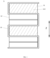
- FIG. 1 is a front view of a laminated battery 1 of the present application.
- the laminated battery 1 includes cathode plates 11, anode plates 12, and a separator 13.
- the cathode plates 11 and the anode plates 12 are stacked alternately in a first direction Z, and the separator 13 is sandwiched between the cathode plates 11 and the anode plates 12.
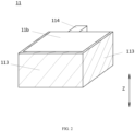
- FIG. 2 is a perspective view of the cathode plate 11 of the laminated battery 1 according to an embodiment of the present application
- FIG. 3 is a perspective view of the cathode plate 11 of the laminated battery 1 with an insulating layer 113 being removed according to an embodiment of the present application.
- a third side face 11e of the cathode 11 faces out of the paper.
- the cathode plate 11 includes a cuboid main body, a cathode tab 114, and an insulating layer 113.
- the cuboid main body is formed by stacking a cathode active material layer 112 and a cathode current collector 111 in the first direction Z.
- the number of the cathode active material layer 112 may be one or two.
- the cathode current collector 111 is sandwiched between the two cathode active material layers 112 in the first direction Z.
- the cuboid main body has four side faces 11c to 11f and two end faces 11a and 11b.
- the two end faces 11a and 11b face each other in the first direction Z.
- the four side faces 11c-11f are a first side face 11c, a second side face 11d, a third side face 11e, and a fourth side face 11f, and are respectively connected to the two end faces 11a, 11b along the first direction Z.
- the cathode tab 114 is formed by the cathode current collector 111 extending from the first side face 11c to an outside of the main body.
- the insulating layer 113 is formed on the second side face 11d to the fourth side face 11f, and covers 95% or more of each of the second side face 11d to the fourth side face 11f.
- FIG. 2 only shows the situation where the insulating layer 113 completely covers (100% coverage) the second side face 11d to the fourth side face 11f, but it is not limited thereto, the burrs can be wrapped as long as the insulating layer 113 has coverage of 95% or more.
- the four side faces 11c ⁇ 11f of the cathode 11 are all cutting surfaces, and the second side face 11d to the fourth side face 11f respectively have an insulating layer 113 with a coverage of 95% or more.
- the insulating layer 113 formed on the second side face 11d to the fourth side face 11f can wrap the burrs formed on the second side face 11d to the fourth side face 11f, thereby preventing short circuits caused by the burrs, and improving the safety performance of the laminated battery 1. Since the first side face 11c has the cathode tab 114, forming the insulating layer 113 on the first side face 11c is relatively complicated.
- an insulating layer 113 with a coverage of 95% or more is formed on the second side face 11d to the fourth side face 11f, and no insulating layer 113 is formed on the first side face 11c having the cathode tab 114, so that the production efficiency of the laminated battery 1 can be improved while improving the safety performance of the laminated battery 1.
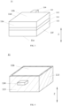
- FIG. 4 is a perspective view of the cathode tab 11 of the laminated battery 1 according to another embodiment of the present application.
- the first side face 11c of the cathode 11 faces out of the paper.
- the insulating layer 113 is also formed on the first side face 11c and covers 95% or more of all other areas in the first side face 11c except the area where the cathode tab 114 is formed.
- the insulating layer 113 completely covers (100% coverage) all other areas of the first side face 11c except the area where the cathode tab 114 is formed, but it is not limited thereto, the burrs can be wrapped as long as the insulating layer 113 has a coverage of 95% or more.
- the insulating layer 113 is not only formed with a coverage of 95% or more on the second side face 11d to the fourth side face 11f, but also formed on the first side face 11c with a coverage of 95% or more on all other areas of the first side face 11c except the area where the cathode tab 114 is formed, thus it can wrap the burrs formed on the first side face 11c to the fourth side face 11f, that is, it can wrap the burrs on all cutting surfaces of the cathode plate 11 and further improve the safety performance of the laminated battery 1.
- FIG. 5 is a cross-sectional view of the cathode plate 11 of the laminated battery 1 of the present application.
- the insulating layer 113 extends from the side faces that are formed with the insulating layer 113 (the second side face 11d to the fourth side face 11f in FIG. 2 , the first side face 11c to the fourth side face 11f in FIG. 4 ) to the end faces 11a and 11b connected to the side faces, and the length W1 extending on the end faces 11a and 11b connected to the side faces is no greater than 0.5 mm.
- the insulating layer 113 formed on the side faces of the cathode plate 11 extends on the end faces connected to the side faces, so the insulating layer 113 can wrap the burrs extending from the side faces to the end faces, preventing the short circuit caused by shrinkage of the separator 13, etc., and the length of the extension is no more than 0.5 mm, so the insulating layer 113 can be prevented from squeezing the anode plate 12 through the separator 13, and further improve the safety performance of the laminated battery 1.
- a thickness D1 of the insulating layer 113 on the side faces where the insulating layer 113 is formed is 2 -30 ⁇ m.
- the thickness of the insulating layer 113 on the side faces on which the insulating layer 113 is formed is no less than 2 ⁇ m, which avoids that the insulating layer 113 is too thin to completely cover the burrs when the burrs are long, and the thickness of the insulating layer 113 on the side faces on which the insulating layer 113 is formed is no more than 30 ⁇ m, which avoids the insulating layer 113 from falling off and forming particles due to the insulating layer 113 being too thick, and improves the safety performance of the laminated battery 1.
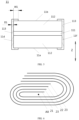
- FIG. 6 is a schematic diagram of the wound battery 2 of the present application viewed along the axial direction AX of winding.
- the wound battery 2 includes a cathode plate 21, an anode plate 22, and a separator 23.
- the cathode plate 21, the anode plate 22, and the separator 23 are wound around the axial direction AX.
- the separator 23 is sandwiched between the cathode plate 21 and the anode plate 22.
- FIG. 7 is a cross-sectional view of the cathode plate 21 of the wound battery 2 according to an embodiment of the present application.
- the cathode plate 21 includes a main body, a cathode tab 214, and an insulating layer 213.
- the main body can be wound in a helical shape around the axial direction AX, and is formed by stacking a cathode active material layer 212 and a cathode current collector 211, the main body has two main faces 21c, 21d, and the two main faces 21c, 21d are two opposite faces along a stacking direction of the cathode active material layer 212 and the cathode current collector 211.
- the number of the cathode active material layer 212 may be one or two.
- the cathode current collector 211 is sandwiched between the two cathode active material layers 212, and the main faces 21c and 21d are formed by the faces of the cathode active material layer 212 away from the cathode current collector 211.
- the cathode tab is formed by the cathode current collector 211 extending from the top face 21a to an outside of the main body along the axial direction AX.
- the top face 21a is perpendicular to the axial direction AX and connects the two main faces 21c and 21d.
- the insulating layer 213 is formed on a bottom face 21b and covers 95% or more of the bottom face 21b.
- the bottom face 21b is opposite to the top face 21a in the axial direction AX and is perpendicular to the axial direction AX and connects the two main faces 21c and 21d.
- FIG. 7 only shows the case where the insulating layer 213 completely covers (100% coverage) the bottom face 21b, but it is not limited thereto, the burrs can be wrapped as long as the insulating layer 213 has a coverage of 95% or more.
- the cathode plate 21 arranged in the wound battery 2 has the top face 21a, the bottom face 21b, and the two main faces 21c and 21d, in which the top face 21a and the bottom face 21b are both cutting surfaces.
- the cathode tab 214 is formed on the top face 21a, and the insulating layer 213 is arranged on the bottom face 21b covering 95% or more of the bottom face 21b.
- the insulating layer 213 formed on the bottom face 21b can wrap the burrs formed on the bottom face 21b, prevent short circuits caused by the burrs, and improve the safety performance of the wound battery.
- the method of forming an insulating layer 213 on the top face 21a is relatively complicated. Therefore, the insulating layer 213 with a coverage of 95% or more is formed on the bottom face 21b, and no insulating layer 213 is formed on the top face 21a having the cathode tab 214, which can improve the production efficiency of the wound battery while improving the safety performance thereof.
- FIG. 8 is a cross-sectional view of the cathode plate 21 of the wound battery 2 according to another embodiment of the present application.
- the insulating layer 213 is also formed on the top face 21a, and covers 95% or more of all other areas in the top face 21a except the area in which the cathode tab 214 is formed.
- FIG. 8 only shows the case where the insulating layer 213 completely covers (100% coverage) all other areas in the top face 21a except the area where the cathode tab 214 is formed, but it is not limited thereto, the burrs can be wrapped as long as the insulating layer 213 has a coverage of 95% or more.
- the insulating layer 213 is not only formed on the bottom face 21b with a coverage of 95% or more, but it is also formed on the top face 21a having the cathode tab 214 and covers 95% or more of all other areas in the top face 21a except the area in which the cathode tab 214 is formed. Therefore, the burrs formed on the top face 21a and the bottom face 21b can be wrapped, that is, the burrs on all the cutting faces of the cathode plate 21 can be wrapped, and the safety performance of the wound battery can be further improved.
- the insulating layer 213 extends from the bottom face 21b to the main faces 21c and 21d connected to the bottom face 21b, and the length W2 extending on the main faces 21c, 21d connected to the bottom face 21b is no greater than 0.5 mm.
- the insulating layer 213 formed on the bottom face 21b of the cathode plate 21 extends on the main faces 21c and 21d connected to the bottom face 21b, so the burrs extending from the bottom face 21b to the main faces 21c and 21d can be wrapped to prevent short circuits caused by shrinkage of the separator 23, etc., and the length of extension is no greater than 0.5 mm, so the insulating layer 213 can be prevented from pressing the anode plate 22 through the separator 23, and the safety performance of the wound battery can be further improved.
- the thickness D2 of the insulating layer 213 on the bottom face 21b is 2 -30 ⁇ m.
- the thickness of the insulating layer 213 on the bottom face 21b is no less than 2 ⁇ m, which avoids that the insulation layer 213 is too thin to completely cover the burrs when the burrs are long, and the thickness of the insulating layer 213 on the bottom face 21b is no more than 30 ⁇ m, which prevents the insulating layer 213 from falling off to form particles due to the insulating layer being too thick, and improves the safety performance of the wound battery.
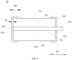
- FIG. 9 is a cross-sectional view of the cathode plate 21 of the wound battery 2 according to still another embodiment of the present application.
- two thinned parts 215 recessed toward the top face 21a are respectively formed on the bottom face 21b in the areas connected to the two main faces 21c and 21d, and the thinned parts 215 are provided with an insulating layer 213.
- the thinned parts 215 recessed toward the top face 21a are respectively formed on the bottom face 21b in the areas close to the two main faces 21c and 21d, and the insulating layer 213 is arranged on the thinned parts 215, so that the insulating layer 213 can be prevented from extending too long on the main faces 21c and 21d and squeezing the anode plate 22 through the separator 23, and the burrs extending from the bottom face 21b to the main faces 21c and 21d are wrapped to further improve the safety performance of the laminated battery 1.
- a total thickness H2 of the insulating layer 213 in each thinned part 215 and the main body (including the cathode active material layer 212 and the cathode current collector 211) is no greater than that a total thickness H3 of the main body (including the cathode active material layer 212 and the cathode current collector 211) outside the thinned parts 215.
- the insulating layer 213 on the thinned parts 215 does not protrude beyond the main faces 21c and 21d of the cathode plate 21, so the insulating layer 213 can be prevented from squeezing the anode plate 22 through the separator 23, and the safety performance of the laminated battery 1 can be further improved.
- the thinned parts 215 are in a cuboid shape, a thickness H1 along a direction perpendicular to the main faces 21c and 21d is 5 ⁇ m or less, and a length L1 along the axial direction AX is 0.5 -5 mm.
- the thinned parts 215 are formed into a cuboid shape, and the thickness along the direction perpendicular to the main faces 21c and 21d is 5 ⁇ m or less, and the length along the axial direction AX is 0.5 -5 mm, so that the insulating layer 213 can wrap the burrs extending from the bottom face 21b to the main faces 21c and 21d without occupying a significant volume of the main body, thereby ensuring that the energy density of the battery is sufficiently high.
- the insulating layers 113, 213 are realized by one of spray coating, spot coating, and dip coating.
- the insulating layers 113, 213 are formed on the cathode plates 11, 21 in advance, the forming method of the insulating layers 113, 213 will not be hindered by the structure of the laminated battery 1 or the wound battery 2, and the insulating layers 113, 213 can be formed by one of spray coating, spot coating, and dip coating, thus the manufacturing process can be simplified.
- a ceramic slurry for forming the insulating layer 113, 213 includes at least a ceramic material, a binder, and a solvent, the ceramic material accounts for 10 -70wt%, and the binder accounts for 1 ⁇ 5wt%, and the viscosity of the ceramic slurry is 100 -1000 mPa ⁇ s.
- the insulating layers 113, 213 are made by using the ceramic slurry including at least the ceramic material, the binder, and the solvent, so the insulating properties and adhesiveness of the insulating layers 113, 213 can be ensured, and since the ceramic material accounts for 10-70wt%, the binder accounts for 1-5wt%, and the viscosity of the ceramic slurry is 100 -1000 mPa ⁇ s, insufficient insulation due to the ceramic material being too little can be avoided, and insufficient adhesion leading to the peeling off of the insulating layers 113, 213 can also be avoided.
- the ceramic material is one of pseudoboehmite, magnesium oxide, silicon carbide, and silicon nitride, preferably pseudoboehmite.
- the binder is one or a combination of polyvinylidene fluoride, polyacrylate, methyl acrylate, ethyl acrylate, 2-methyl methacrylate, and 2-ethyl methacrylate, preferably polyvinylidene fluoride.
- the solvent is N-methylpyrrolidone.
- a cathode active material was coated on both sides of a cathode current collector, after cold pressing and cutting, a plurality of main bodies of a cathode plate with burrs on the cutting surfaces (the first side face to the fourth side face) were obtained.
- the main bodies of the cathode plate were stacked with each other, and a ceramic slurry was spray-coated on the first side face to the fourth side face, except for the cathode tab, completely covering (100% coverage) the first side face to the fourth side face, and a length extending on an end face is no more than 0.5 mm, and then was dried to obtain a cathode plate.
- the ceramic material accounted for 60wt%, the binder accounted for 5wt%, and the viscosity of the ceramic slurry was 800 mPa ⁇ s.
- the thickness of the insulating layer was 10 ⁇ m, and the length extending on the end face of the cathode plate is no more than 0.5 mm.
- An anode active material was coated on both sides of an anode current collector, and after cold pressing and cutting, an anode plate was obtained.
- the separator was folded in a Z shape, and a laminated battery of Example 1 was obtained by assembling in an order of "separator-anode plate-separator-cathode plate-separator-anode plate."
- a design in which the cathode plate exceeded the anode plate was adopted.
- a laminated battery of Example 2 was obtained in the same manner as in Example 1, except that no insulating layer was coated on a first side face where a cathode tab was arranged.
- a laminated battery of Comparative Example 1 was obtained in the same manner as in Example 1, except that no insulating layer was coated on a cathode plate.
- a laminated battery of Comparative Example 2 was obtained in the same manner as in Example 1, except that a thickness of the insulating layer was 1 ⁇ m.
- a hundred laminated batteries were prepared according to the respective above-mentioned Example 1, Example 2, Comparative Example 1, and Comparative Example 2, and an insulation withstand voltage test (Hi-pot test) was carried out on these laminated batteries to detect whether there were burrs penetrating the separator.
- the number of batteries that fail the insulation withstand voltage test was recorded, and their percentage to the total number was calculated and recorded in the column of the probability of burrs penetrating the separator in Table 1.
- additional ten laminated batteries were prepared respectively, which have an overhung design with the cathode plate designed to exceed the anode plate (overhang).
- Table 1 shows the evaluation results of laminated batteries. It can be found from Table 1, when no insulating layer was arranged on the cutting surfaces of the cathode plate, as in Comparative Example 1, the burrs on the cutting surfaces were exposed, and the risk of burrs penetrating the separator was extremely high, with a probability of 75%. The risk of cycle charging failure caused by lithium deposition and burrs or aluminum leakage caused by the cathode plate exceeding the anode plate was also the greatest, and all ten laminated batteries failed.
- Example 1 of the present application after the four cut surfaces, that is, the first side face to the fourth side face, of the cathode plate of the laminated battery were coated with an insulating layer having a certain thickness, the risk of short circuit caused by ruptured separator by the burrs and the risk of cycle charging failure were lowered to a minimum.
- the first side face of the laminated battery has a cathode tab protruding from the main body, coating an insulating layer on the first side face is relatively complicated, which affects production efficiency.
- coating the insulating layer on other cutting surfaces other than the first side face, that is, the second side face to the fourth side face could also better reduce the risk of short circuit caused by burrs penetrating the separator and the risk of cycle charging failure, while taking into account the production efficiency.
- a cathode active material was coated on both sides of the cathode current collector, after cold pressing and cutting, main bodies of a cathode plate with burrs on a plurality of cutting surfaces (a top face and a bottom face) was obtained, the main bodies of the cathode plate were stacked, a ceramic slurry was spray-coated on the top and bottom faces, completely covering (100% coverage) the top and bottom faces except for the cathode tab, and a length extending on main faces was no greater than 0.5 mm, and then was dried to obtain the cathode plate.
- a ceramic material accounted for 60wt%, a binder accounted for 5wt%, and the viscosity of the ceramic slurry was 800 mPa ⁇ s.
- the thickness of the insulating layer on the cut surfaces was 10 ⁇ m, and the length extending on the main faces of the cathode plate was no more than 0.5 mm.
- An anode active material was coated on both sides of an anode current collector, and after cold pressing and cutting, the anode plate was obtained.
- the components were placed in an order of "separator-anode plate-separator-cathode plate", one end of the cathode plate, the anode plate, and two separators was fixed on a discharge roller, and the other end was stacked together and fixed on a winding shaft.
- a motor was used to rotate the winding shaft to wind the cathode plate, the anode plate, and the two separators to obtain a wound battery of Example 3.
- Example 4 A wound battery of Example 4 was obtained in the same manner as in Example 3, except that no insulating layer was coated on a top face where a cathode tab was arranged.
- a wound battery of Example 5 was obtained in the same manner as in Example 3, except that no insulating layer was coated on a top face where a cathode tab was arranged, and thinned parts having an insulating layer were formed on a bottom face, a length of the thinned parts along an axial direction was 5 mm, and a thickness of the insulating layer in the thinned parts was 5 ⁇ m.
- a wound battery of Comparative Example 3 was obtained in the same manner as in Example 3, except that no insulating layer was coated on the cathode plate.
- a wound battery of Comparative Example 4 was obtained in the same manner as in Example 3, except that no insulating layer was coated on a top face where a cathode tab was arranged, and thinned parts having an insulating layer were formed on a bottom face, a length of the thinned parts along an axial direction was 5 mm, and a thickness of the insulating layer in the thinned parts was 2 ⁇ m.
- a wound battery of Comparative Example 5 was obtained in the same manner as in Example 3, except that no insulating layer was coated on a top face where a cathode tab was arranged, and thinned parts having an insulating layer were formed on a bottom face, a length of the thinned parts along an axial direction was 5 mm, a thickness of the insulating layer in the thinned parts was 10 ⁇ m, and a thickness of the insulating layer on the bottom face was 1 ⁇ m.
- Example 3-Example 5 A hundred wound batteries were prepared according to the respective above-mentioned Example 3-Example 5, and Comparative Example 3-Comparative Example 5, and an insulation withstand voltage test (Hi-pot test) was carried out on these wound batteries to detect whether there were burrs penetrating the separator. The number of batteries that fail the insulation withstand voltage test was recorded, and their percentage to the total number was calculated and recorded in the column of the probability of burrs penetrating the separator in Table 2.
- additional ten wound batteries were prepared respectively, in which the cathode plate was designed to exceed the anode plate (overhang).
- Table 2 shows the evaluation results of wound batteries. According to Table 2, when no insulating layer was provided on the cutting surfaces of the cathode plate, that is, the top face and the bottom face, as in Comparative Example 3, the probability of burrs on the cutting edges penetrating the separator was extremely high, and the risk of short circuit caused by burrs penetrating the separator was at a maximum, and the risk of cycle charging failure after the lithium dendrite overlapped the burrs was also the greatest.
- the insulating layer of the thinned parts can effectively prevent the short circuit caused by the direct overlap between the cathode plate and the anode plate, and effectively prevent cycle charging failure due to the lithium dendrite overlapping the burrs, as in Example 5.
- laminated batteries and wound batteries were produced in the same manner as in the above-mentioned Examples 1-5 and the above-mentioned Comparative Examples 1-5 except for changing the degree of coverage of the insulating layer, such as changing to 95% and 98%, and evaluations were carried out according to the evaluation methods in Table 1 and Table 2.
- the short-circuit risk caused by the burrs penetrating the separator was slightly higher than when the coverage was 100%, and the probability of the burrs penetrating the separator was 15% or less, and the failure probability after the burrs overlapped lithium dendrites was less than 1/10, which were all within the range that can fully ensure the safety of the battery.
Landscapes
- Chemical & Material Sciences (AREA)
- Chemical Kinetics & Catalysis (AREA)
- Electrochemistry (AREA)
- General Chemical & Material Sciences (AREA)
- Engineering & Computer Science (AREA)
- Manufacturing & Machinery (AREA)
- Materials Engineering (AREA)
- Secondary Cells (AREA)
- Connection Of Batteries Or Terminals (AREA)
- Battery Electrode And Active Subsutance (AREA)
- Primary Cells (AREA)
Abstract
Description
- The present application relates to the technical field of batteries, and in particular, to a cathode plate and a battery.
- In recent years, with the continuous development of lithium-ion battery technology, lithium-ion batteries are widely used in energy storage power systems such as water power, firepower, wind power, and solar power stations, as well as fields like power tools, electric bicycles, electric motorcycles, electric vehicles, military equipment, aerospace, and the like. Due to the great development of lithium-ion batteries, higher requirements have been raised for their safety performance, and so on.
- The manufacture of the laminated lithium-ion battery and the wound lithium-ion battery both require the cutting of electrode plates. Especially when cutting a cathode plate, it is easy to produce burrs on the cutting surface of the cathode plate, and the burrs may penetrate the separator, or, due to the design of the cathode plate exceeding the anode plate (overhang), when the separator shrinks, burrs on the cutting edge of the cathode plate overlap with the anode plate, or, lithium precipitation forms when the cathode plate exceeds the anode plate after the electrode plates are misaligned, and the lithium dendrites overlap with the burrs or leaked aluminum (leaked cathode current collector), which causes a short circuit and affects the safety performance of the battery.
- The technical problem to be solved in the present application:
In view of the above technical problems, an objective of the present application provides a cathode plate and a battery, which prevent the short circuit caused by burrs and improve the safety performance. - Technical proposals to overcome the technical problems:
In order to achieve at least the above objective, the present application provides a cathode plate and a battery. - A first aspect of the present application provides a cathode plate, which is arranged in a laminated battery, including: a cuboid main body, formed by stacking a cathode active material layer and a cathode current collector in a first direction, the main body having four side faces and two end faces, the two end faces being arranged oppositely to each other in the first direction, and the four side faces being the first side face to the fourth side face and being respectively connected to the two end faces along the first direction; a cathode tab, formed by the cathode current collector extending from the first side face to an outside of the main body; and an insulating layer, formed on the second side face to the fourth side face and covering 95% or more of each side face of the second side face to the fourth side face.
- The electrode plate that can be arranged in the laminated battery of the present application has four side faces, and the four side faces are all cutting surfaces, the cathode tab is located on the first side face, and the insulating layer is provided on the second to the fourth side faces and covers 95% or more of each side face of the second to fourth side faces. Thus, the insulating layer formed on the second to the fourth side faces can wrap the burrs formed on the second to the fourth side faces, thereby preventing a short circuit caused by the burrs and improving the safety performance of the laminated battery. In addition, since the cathode tab is located on the first side face, the method for forming an insulating layer on the first side is relatively complicated. Therefore, an insulating layer with a coverage of 95% or higher is formed on the second to the fourth side faces respectively, and no insulating layer is formed on the first side face having the cathode tab, which can improve the safety performance of the laminated battery, such that the production efficiency of the laminated battery is improved.
- In some implementations, the insulating layer is also formed on the first side face and covers 95% or more of all other areas of the first side face except an area where the cathode tab is formed.
- Accordingly, the insulating layer is not only formed with a coverage of 95% or more on the second side face to the fourth side face, but also formed with a coverage of 95% or more on all other areas of the first side face except the area where the cathode tab is formed, thus it can wrap the burrs formed on the first side face to the fourth side face, that is, it can wrap the burrs on all cutting surfaces of the cathode plate and further improve the safety performance of the laminated battery.
- In some implementations, the insulating layer extends from the side faces on which the insulating layer is formed to the end faces connected to the side faces, and a length extending on the end faces that are connected to the side face is no more than 0.5 mm.
- Accordingly, the insulating layer formed on the side faces of the cathode plate extends on the end faces connected to the side faces, so the insulating layer can wrap the burrs extending from the side faces to the end faces, preventing the short circuit caused by shrinkage of the separator, etc., and the length of the extension is no more than 0.5 mm, so the insulating layer can prevent the anode plate from being squeezed through the separator due to excessive insulating layers, and further improve the safety performance of the laminated battery.
- In some implementations, a thickness of the insulating layer on the side faces on which the insulating layer is formed is 2 -30 µm.
- Accordingly, the thickness of the insulating layer on the side faces on which the insulating layer is formed is no less than 2 µm, which avoids that the insulating layer is too thin to completely cover the burrs when the burrs are long, and the thickness of the insulating layer on the side faces on which the insulating layer is formed is no more than 30 µm, which avoids the insulating layer from falling off and forming particles due to the insulating layer being too thick, and improves the safety performance of the laminated battery.
- A second aspect of the present application provides a cathode plate, which is arranged in a wound battery, including: a main body capable of being wound into a helical shape around an axial direction, the main body being formed by stacking a cathode active material layer and a cathode current collector, the main body having two main faces, and the two main faces being two opposite faces along a stacking direction of the cathode active material layer and the cathode current collector; a cathode tab, which is formed by the cathode current collector extending from a top face to an outside of the main body along the axial direction, the top face being perpendicular to the axial direction and connected with the two main faces; and an insulating layer, which is formed on a bottom face and covering 95% or more of the bottom face, the bottom face being opposite to the top face in the axial direction and being perpendicular to the axial direction and connected with the two main faces.
- The cathode plate that can be arranged in a wound battery of the present application has a top face, a bottom face, and two main faces, in which the top face and the bottom face are both cutting surfaces, and an insulating layer is arranged on the bottom face covering 95% or more of the bottom face. Thus, the insulating layer formed on the bottom face can wrap the burrs formed on the bottom face, prevent short circuits caused by the burrs, and improve the safety performance of the wound battery. In addition, since the top face has a cathode tab, the method of forming an insulating layer on the top face is relatively complicated. Therefore, an insulating layer with a coverage of 95% or more is formed on the bottom face, and no insulating layer is formed on the top face having the cathode tab, which can improve the production efficiency of the wound battery while improving the safety performance thereof.
- In some implementations, the insulating layer extends from the bottom face to the main faces connected to the bottom face, and a length extending on the main faces connected to the bottom face is no greater than 0.5 mm.
- Accordingly, the insulating layer formed on the bottom face of the cathode plate extends on the main faces connected to the bottom face, so the burrs extending from the bottom face to the main faces can be wrapped to prevent short circuits caused by shrinkage of the separator, etc., and the length of the extension is no greater than 0.5 mm, so the insulating layer can be prevented from pressing the anode plate through the separator, and the safety performance of the wound battery can be further improved.
- In some implementations, a thickness of the insulating layer on the bottom face is 2 µm -30 µm.
- Accordingly, the thickness of the insulating layer on the bottom face is no less than 2 µm, which avoids that the insulation layer is too thin to completely cover the burrs when the burrs are long, and the thickness of the insulating layer on the bottom face is no more than 30 µm, which prevents the insulating layer from falling off to form particles due to the insulating layer being too thick, and improves the safety performance of the wound battery.
- In some implementations, two thinned parts recessed toward the top face are respectively provided on the bottom face in areas connected to the two main faces, and the insulating layer is arranged on the thinned parts.
- Accordingly, the thinned parts recessed toward the top face are respectively formed on the bottom face in the areas close to the two main faces, and the insulating layer is arranged on the thinned parts, so that the insulating layer can be prevented from extending too long on the main faces and squeezing the anode plate through the separator, and the burrs extending from the bottom face to the main faces are wrapped to further improve the safety performance of the laminated battery.
- In some implementations, a sum of thicknesses of the insulating layer in each thinned part and the main body is no greater than a thickness of the main body outside the thinned parts.
- Accordingly, the insulating layer on the thinned parts does not protrude beyond the main faces of the cathode plate, so the insulating layer can be prevented from squeezing the anode plate through the separator, and the safety performance of the laminated battery can be further improved.
- In some implementations, the thinned parts are in a cuboid shape, a thickness along a direction perpendicular to the main faces is 5 µm or less, and a length along the axial direction is 0.5 -5 mm.
- Accordingly, the thinned parts are formed into a cuboid shape, and the thickness along the direction perpendicular to the main faces is 5 µm or less, and the length along the axial direction is 0.5 -5 mm, so that the insulating layer can wrap the burrs extending from the bottom face to the main faces without occupying a significant volume of the main body, thereby ensuring that the energy density of the battery is sufficiently high.
- With respect to the cathode plates of the first aspect and the second aspect of the present application, in some implementations, the insulating layer is coated by one of spray coating, spot coating, and dip coating.
- Since the insulating layer is formed on the cathode plate in advance, the forming of the insulating layer will not be hindered by the structure of the laminated battery or the wound battery, and the insulating layer can be formed by one of spray coating, spot coating, and dip coating, thereby simplifying the manufacturing process.
- With respect to the cathode plate of the first aspect and the second aspect of the present application, in some implementations, a ceramic slurry for making the insulating layer includes at least a ceramic material, a binder, and a solvent, and the ceramic material accounts for 10 - 70wt%, the binder accounts for 1-5wt%, and a viscosity of the ceramic slurry is 100 -1000 mPa·s.
- Accordingly, the insulating layer is made of the ceramic slurry including at least a ceramic material, a binder, and a solvent, so the insulation and adhesion of the insulating layer can be ensured, and the ceramic material accounts for 10 -70wt%, the binder accounts for 1 -5wt%, and the viscosity of the ceramic slurry is 100 -1000 mPa·s, which avoids the insufficient insulation due to the ceramic material being little, or the insufficient adhesion that will cause the insulating layer to fall off due to excessive ceramic material.
- With respect to the cathode plates of the first aspect and the second aspect of the present application, in some implementations, the ceramic material is one of pseudoboehmite, magnesium oxide, silicon carbide, and silicon nitride, preferably pseudoboehmite; the binder is one or a combination of polyvinylidene fluoride, polyacrylate, methyl acrylate, ethyl acrylate, 2-methyl methacrylate, and 2-ethyl methacrylate, preferably polyvinylidene fluoride; and the solvent is N-methylpyrrolidone.
- Accordingly, adopting the above materials that are cheap and easy to obtain can reduce manufacturing costs to facilitate industrial production.
- A third aspect of the present application provides a battery, which includes the cathode plate of the above-mentioned first aspect, an anode plate, and a separator, the cathode plate and the anode plate are alternately stacked in the first direction, and the separator is sandwiched between the cathode plate and the anode plate.
- A fourth aspect of the present application provides a battery, which includes the cathode plate of the above-mentioned second aspect, an anode plate, and a separator, the cathode plate, the anode plate, and the separator are wound around the axial direction, and the separator is sandwiched between the cathode plate and the anode plate.
- The advantageous effects of the present application are as follows:
The present application provides a cathode plate and a battery, which prevent a short circuit caused by burrs and improve the safety performance of the battery. -
-
FIG. 1 is a front view of the laminated battery according to the present application; -
FIG. 2 is a perspective view of the cathode plate of the laminated battery according to an embodiment of the present application; -
FIG. 3 is a perspective view of the cathode plate of the laminated battery with the insulating layer being removed according to an embodiment of the present application; -
FIG. 4 is a perspective view of the cathode plate of the laminated battery according to another embodiment of the present application; -
FIG. 5 is a cross-sectional view of the cathode plate of the laminated battery according to the present application; -
FIG. 6 is a schematic diagram of the wound battery according to the present application viewing along the axial direction of winding; -
FIG. 7 is a cross-sectional view of the cathode plate of the wound battery according to an embodiment of the present application; -
FIG. 8 is a cross-sectional view of the cathode plate of the wound battery according to another embodiment of the present application; and -
FIG. 9 is a cross-sectional view of the cathode plate of the wound battery according to yet another embodiment of the present application. - Reference numbers in the drawings are as follows:
1 laminated battery; 11 cathode plate; 12 anode plate; 13 separator; 111 cathode current collector; 112 cathode active material layer; 113 insulating layer; 114 cathode tab; 11a, 11b end faces; 11c first side face; 11d second side face; 11e third side face; 11f fourth side face; 2 wound battery; 21 cathode plate; 22 anode plate; 23 separator; 211 cathode current collector; 212 cathode active material layer; 213 insulating layer; 214 cathode tab; 215 thinned part; 21a top face; 21b bottom face; and 21c, 21d main faces. - Hereinafter, embodiments of a cathode plate and a battery of the present application will be specifically disclosed in detail with reference to the accompanying drawings. However, unnecessary detailed description may be omitted. For example, detailed descriptions of well-known items and repeated descriptions of substantially the same configurations may be omitted. This is to avoid the following description from becoming unnecessarily lengthy and to facilitate the understanding of those skilled in the art. In addition, the drawings and the following descriptions are provided for those skilled in the art to fully understand the present application, and are not intended to limit the subject matter described in the claims.
- The "range" disclosed in the application is defined in the form of lower limit and upper limit, and the given range is limited by selecting a lower limit and an upper limit, and the selected lower limit and upper limit define the boundary of a special range. Ranges defined in this manner may be inclusive or exclusive and may be combined arbitrarily, i.e., any lower limit may be combined with any upper limit to form a range. For example, if ranges of 60-120 and 80-110 are listed for a particular parameter, it is understood that ranges of 60-110 and 80-120 are contemplated. Additionally, if the
minimum range values 1 and 2 are listed, and if the maximum range values 3, 4, and 5 are listed, the following ranges are all expected: 1-3, 1-4, 1-5, 2- 3, 2-4, and 2-5. In this application, unless otherwise stated, the numerical range "a-b" represents an abbreviated representation of any combination of real numbers between a and b, where a and b are both real numbers. For example, the numerical range "0-5" indicates that all real numbers between "0-5" have been listed in this article, and "0-5" is only an abbreviated representation of the combination of these values. In addition, when expressing that a certain parameter is an integer ≥ 2, it is equivalent to disclosing that the parameter is an integer such as 2, 3, 4, 5, 6, 7, 8, 9, 10, 11, 12, etc. - Unless otherwise specified, all implementation modes and optional implementation modes of the present application may be combined with each other to form new technical proposals.
- Unless otherwise specified, all technical features and optional technical features of the present application may be combined with each other to form new technical proposals.
- Unless otherwise specified, all the steps in the present application may be performed sequentially or randomly, preferably sequentially. For example, the method including steps (a) and (b) means that the method may include steps (a) and (b) performed in sequence, and may also include steps (b) and (a) performed in sequence. For example, mentioning that the method may also include step (c), means that step (c) may be added to the method in any order, for example, the method may include steps (a), (b) and (c), may also include steps (a), (c) and (b), and may also include steps (c), (a) and (b).
- Unless otherwise specified, "include" and "comprise" mentioned in the application represent an open type or a closed type. For example, the "include" and "comprise" may mean that other components not listed may be included or comprised, or only listed components may be included or comprised.
- Unless otherwise specified, in this application, the term "or" is inclusive. For example, the phrase "A or B" means "A, B, or both A and B." More specifically, the condition "A or B" is satisfied by either: A is true (or exists) and B is false (or does not exist); A is false (or does not exist) and B is true (or exists); or both A and B are true (or exist).
- The inventors noticed that the manufacturing processes of a laminated lithium-ion battery and a wound lithium-ion battery both require cutting of the electrode plate. The electrode plate is formed by a current collector sandwiched by two layers of electrode active materials, or stacking of a layer of electrode active material layer and a current collector, in which the current collector of the cathode plate is composed of a metal foil (usually an aluminum foil), when cutting along the stacking direction, the cathode current collector is prone to produce burrs. The burrs may penetrate the separator sandwiched between the cathode plate and the anode plate, causing a short circuit as the burrs contact the cathode plate or the anode plate. In addition, due to the dislocation of the electrode plates that are prone to occur in the laminated battery, or the design of the cathode plate exceeding the anode plate (overhang) in the wound battery, the cathode plate exceeds the anode plate and lithium is deposited, thus when burrs exist, the burrs are likely to overlap with the lithium dendrite, resulting risk of short-circuit failure. Therefore, the burrs will affect the safety performance of the battery.
- In the existing technology, in a laminated battery with a Z-shaped separator, that is, a continuous separator, the laminated cathode plate and anode plate have one side wrapped by the separator, the burrs on the one side cannot be completely covered by spray coating, brush coating, spot coating, or dip coating. In addition, in a wound battery, glue is applied to the edges of the wound cathode plate, separator, and anode plate to reduce the probability of burrs on the cutting edge, however, the separator is longer than the anode plate and the anode plate is longer than the cathode plate, that is, the edges of the separator, the cathode plate, and the anode plate are not on the same plane, so it is difficult to cover the burrs on the cutting edge of the cathode plate by spray coating, brush coating, spot coating, or dip coating.
- Therefore, a first aspect of the present application provides a cathode plate, which is arranged in a laminated battery, including: a cuboid main body, cathode tab, and an insulating layer; the main body is formed by stacking a cathode active material layer and a cathode current collector in a first direction, the main body has four side faces and two end faces, the two end faces face each other in the first direction, and the four side faces are the first side face to the fourth side face and are respectively connected to the two end faces along the first direction; the cathode tab is formed by the cathode current collector extending from the first side face to an outside of the main body; and the insulating layer is formed on the second side face to the fourth side face and covers 95% or more of each side face of the second side face to the fourth side face.
- The electrode plate that can be arranged in the laminated battery of the present application has four side faces, and the four side faces are all cutting surfaces, the cathode tab is located on the first side face, and the insulating layer is provided on the second to the fourth side faces and covers 95% or more of each side face of the second to the fourth side faces. Thus, the insulating layer formed on the second to the fourth side faces can wrap the burrs formed on the second to the fourth side faces, thereby preventing a short circuit caused by the burrs and improving the safety performance of the laminated battery. In addition, since the cathode tab is located on the first side face, the method for forming an insulating layer on the first side is relatively complicated. Therefore, an insulating layer with a coverage of 95% or higher is formed on the second to the fourth side faces respectively, and no insulating layer is formed on the first side face having the cathode tab, which can improve the safety performance of the laminated battery, such that the production efficiency of the laminated battery is improved.
- A second aspect of the present application provides a cathode plate, which is arranged in a wound battery, including: a main body, a cathode tab, and an insulating layer; the main body can be wound into a helical shape around an axial direction, and is formed by stacking a cathode active material layer and a cathode current collector, the main body has two main faces, and the two main faces are two opposite faces along a stacking direction of the cathode active material layer and the cathode current collector; the cathode tab is formed by the cathode current collector extending from the top face to an outside of the main body along the axial direction, the top face is perpendicular to the axial direction and connects the two main faces; and the insulating layer is formed on a bottom face and covers 95% or more of the bottom face, the bottom face is opposite to the top face in the axial direction and perpendicular to the axial direction and connects the two main faces.
- The cathode plate that can be arranged in a wound battery of the present application has a top face, a bottom face, and two main faces, in which the top face and the bottom face are both cutting surfaces, and an insulating layer is arranged on the bottom face covering 95% or more of the bottom face. Thus, the insulating layer formed on the bottom face can wrap the burrs formed on the bottom face, prevent short circuits caused by the burrs, and improve the safety performance of the wound battery. In addition, since the top face has a cathode tab, the method of forming an insulating layer on the top face is relatively complicated. Therefore, an insulating layer with a coverage of 95% or more is formed on the bottom face, and no insulating layer is formed on the top face having the cathode tab, which can improve the production efficiency of the wound battery while improving the safety performance thereof.
- A third aspect of the present application provides a battery, which includes the cathode plate of the above-mentioned first aspect, an anode plate, and a separator, the cathode plate and the anode plate are alternately stacked in the first direction, and the separator is sandwiched between the cathode plate and the anode plate.
- A fourth aspect of the present application provides a battery, which includes the cathode plate of the above-mentioned second aspect, an anode plate, and a separator, the cathode plate, the anode plate, and the separator are wound around the axial direction, and the separator is sandwiched between the cathode plate and the anode plate.
- Hereinafter, the present application will be described in detail with reference to the accompanying drawings.
- First, a laminated battery and a cathode plate thereof will be described.
FIG. 1 is a front view of alaminated battery 1 of the present application. As shown inFIG. 1 , thelaminated battery 1 includescathode plates 11,anode plates 12, and aseparator 13. Thecathode plates 11 and theanode plates 12 are stacked alternately in a first direction Z, and theseparator 13 is sandwiched between thecathode plates 11 and theanode plates 12. -
FIG. 2 is a perspective view of thecathode plate 11 of thelaminated battery 1 according to an embodiment of the present application, andFIG. 3 is a perspective view of thecathode plate 11 of thelaminated battery 1 with an insulatinglayer 113 being removed according to an embodiment of the present application. InFIGS. 2 and3 , athird side face 11e of thecathode 11 faces out of the paper. As shown inFIGS. 2 and3 , thecathode plate 11 includes a cuboid main body, acathode tab 114, and an insulatinglayer 113. The cuboid main body is formed by stacking a cathodeactive material layer 112 and a cathodecurrent collector 111 in the first direction Z. The number of the cathodeactive material layer 112 may be one or two. When the number of the cathodeactive material layer 112 is two, as shown inFIG. 3 , the cathodecurrent collector 111 is sandwiched between the two cathode active material layers 112 in the first direction Z. As shown inFIG. 3 , the cuboid main body has four side faces 11c to 11f and two end faces 11a and 11b. The two end faces 11a and 11b face each other in the first direction Z. The four side faces 11c-11f are afirst side face 11c, asecond side face 11d, athird side face 11e, and afourth side face 11f, and are respectively connected to the two end faces 11a, 11b along the first direction Z. Thecathode tab 114 is formed by the cathodecurrent collector 111 extending from thefirst side face 11c to an outside of the main body. The insulatinglayer 113 is formed on thesecond side face 11d to thefourth side face 11f, and covers 95% or more of each of thesecond side face 11d to thefourth side face 11f.FIG. 2 only shows the situation where the insulatinglayer 113 completely covers (100% coverage) thesecond side face 11d to thefourth side face 11f, but it is not limited thereto, the burrs can be wrapped as long as the insulatinglayer 113 has coverage of 95% or more. - The four side faces 11c~11f of the
cathode 11 are all cutting surfaces, and thesecond side face 11d to thefourth side face 11f respectively have aninsulating layer 113 with a coverage of 95% or more. Thus, the insulatinglayer 113 formed on thesecond side face 11d to thefourth side face 11f can wrap the burrs formed on thesecond side face 11d to thefourth side face 11f, thereby preventing short circuits caused by the burrs, and improving the safety performance of thelaminated battery 1. Since thefirst side face 11c has thecathode tab 114, forming the insulatinglayer 113 on thefirst side face 11c is relatively complicated. Therefore, an insulatinglayer 113 with a coverage of 95% or more is formed on thesecond side face 11d to thefourth side face 11f, and no insulatinglayer 113 is formed on thefirst side face 11c having thecathode tab 114, so that the production efficiency of thelaminated battery 1 can be improved while improving the safety performance of thelaminated battery 1. -
FIG. 4 is a perspective view of thecathode tab 11 of thelaminated battery 1 according to another embodiment of the present application. InFIG. 4 , thefirst side face 11c of thecathode 11 faces out of the paper. As shown inFIG. 4 , in some embodiments, the insulatinglayer 113 is also formed on thefirst side face 11c and covers 95% or more of all other areas in thefirst side face 11c except the area where thecathode tab 114 is formed.FIG. 4 only shows that the insulatinglayer 113 completely covers (100% coverage) all other areas of thefirst side face 11c except the area where thecathode tab 114 is formed, but it is not limited thereto, the burrs can be wrapped as long as the insulatinglayer 113 has a coverage of 95% or more. - Accordingly, the insulating
layer 113 is not only formed with a coverage of 95% or more on thesecond side face 11d to thefourth side face 11f, but also formed on thefirst side face 11c with a coverage of 95% or more on all other areas of thefirst side face 11c except the area where thecathode tab 114 is formed, thus it can wrap the burrs formed on thefirst side face 11c to thefourth side face 11f, that is, it can wrap the burrs on all cutting surfaces of thecathode plate 11 and further improve the safety performance of thelaminated battery 1. -
FIG. 5 is a cross-sectional view of thecathode plate 11 of thelaminated battery 1 of the present application. As shown inFIGS. 2 ,4 , and5 , in some embodiments, the insulatinglayer 113 extends from the side faces that are formed with the insulating layer 113 (thesecond side face 11d to thefourth side face 11f inFIG. 2 , thefirst side face 11c to thefourth side face 11f inFIG. 4 ) to the end faces 11a and 11b connected to the side faces, and the length W1 extending on the end faces 11a and 11b connected to the side faces is no greater than 0.5 mm. - Accordingly, the insulating
layer 113 formed on the side faces of thecathode plate 11 extends on the end faces connected to the side faces, so the insulatinglayer 113 can wrap the burrs extending from the side faces to the end faces, preventing the short circuit caused by shrinkage of theseparator 13, etc., and the length of the extension is no more than 0.5 mm, so the insulatinglayer 113 can be prevented from squeezing theanode plate 12 through theseparator 13, and further improve the safety performance of thelaminated battery 1. - As shown in
FIG. 5 , in some embodiments, a thickness D1 of the insulatinglayer 113 on the side faces where the insulatinglayer 113 is formed is 2 -30 µm. - Accordingly, the thickness of the insulating
layer 113 on the side faces on which the insulatinglayer 113 is formed is no less than 2 µm, which avoids that the insulatinglayer 113 is too thin to completely cover the burrs when the burrs are long, and the thickness of the insulatinglayer 113 on the side faces on which the insulatinglayer 113 is formed is no more than 30 µm, which avoids the insulatinglayer 113 from falling off and forming particles due to the insulatinglayer 113 being too thick, and improves the safety performance of thelaminated battery 1. - Hereafter, a wound battery and a cathode plate therein will be described.
FIG. 6 is a schematic diagram of the wound battery 2 of the present application viewed along the axial direction AX of winding. As shown inFIG. 6 , the wound battery 2 includes acathode plate 21, ananode plate 22, and aseparator 23. Thecathode plate 21, theanode plate 22, and theseparator 23 are wound around the axial direction AX. Theseparator 23 is sandwiched between thecathode plate 21 and theanode plate 22. -
FIG. 7 is a cross-sectional view of thecathode plate 21 of the wound battery 2 according to an embodiment of the present application. Thecathode plate 21 includes a main body, acathode tab 214, and an insulatinglayer 213. The main body can be wound in a helical shape around the axial direction AX, and is formed by stacking a cathodeactive material layer 212 and a cathodecurrent collector 211, the main body has twomain faces main faces active material layer 212 and the cathodecurrent collector 211. The number of the cathodeactive material layer 212 may be one or two. When the number of the cathode active material layers 112 is two, as shown inFIGS. 7-9 , the cathodecurrent collector 211 is sandwiched between the two cathode active material layers 212, and themain faces active material layer 212 away from the cathodecurrent collector 211. The cathode tab is formed by the cathodecurrent collector 211 extending from thetop face 21a to an outside of the main body along the axial direction AX. Thetop face 21a is perpendicular to the axial direction AX and connects the twomain faces layer 213 is formed on abottom face 21b and covers 95% or more of thebottom face 21b. Thebottom face 21b is opposite to thetop face 21a in the axial direction AX and is perpendicular to the axial direction AX and connects the twomain faces FIG. 7 only shows the case where the insulatinglayer 213 completely covers (100% coverage) thebottom face 21b, but it is not limited thereto, the burrs can be wrapped as long as the insulatinglayer 213 has a coverage of 95% or more. - The
cathode plate 21 arranged in the wound battery 2 has thetop face 21a, thebottom face 21b, and the twomain faces top face 21a and thebottom face 21b are both cutting surfaces. Thecathode tab 214 is formed on thetop face 21a, and the insulatinglayer 213 is arranged on thebottom face 21b covering 95% or more of thebottom face 21b. Thus, the insulatinglayer 213 formed on thebottom face 21b can wrap the burrs formed on thebottom face 21b, prevent short circuits caused by the burrs, and improve the safety performance of the wound battery. In addition, since thetop face 21a has thecathode tab 214, the method of forming an insulatinglayer 213 on thetop face 21a is relatively complicated. Therefore, the insulatinglayer 213 with a coverage of 95% or more is formed on thebottom face 21b, and no insulatinglayer 213 is formed on thetop face 21a having thecathode tab 214, which can improve the production efficiency of the wound battery while improving the safety performance thereof. -
FIG. 8 is a cross-sectional view of thecathode plate 21 of the wound battery 2 according to another embodiment of the present application. As shown inFIG. 8 , in some embodiments, the insulatinglayer 213 is also formed on thetop face 21a, and covers 95% or more of all other areas in thetop face 21a except the area in which thecathode tab 214 is formed.FIG. 8 only shows the case where the insulatinglayer 213 completely covers (100% coverage) all other areas in thetop face 21a except the area where thecathode tab 214 is formed, but it is not limited thereto, the burrs can be wrapped as long as the insulatinglayer 213 has a coverage of 95% or more. - Accordingly, the insulating
layer 213 is not only formed on thebottom face 21b with a coverage of 95% or more, but it is also formed on thetop face 21a having thecathode tab 214 and covers 95% or more of all other areas in thetop face 21a except the area in which thecathode tab 214 is formed. Therefore, the burrs formed on thetop face 21a and thebottom face 21b can be wrapped, that is, the burrs on all the cutting faces of thecathode plate 21 can be wrapped, and the safety performance of the wound battery can be further improved. - As shown in
FIG. 7 , in some embodiments, the insulatinglayer 213 extends from thebottom face 21b to themain faces bottom face 21b, and the length W2 extending on themain faces bottom face 21b is no greater than 0.5 mm. - Accordingly, the insulating
layer 213 formed on thebottom face 21b of thecathode plate 21 extends on themain faces bottom face 21b, so the burrs extending from thebottom face 21b to themain faces separator 23, etc., and the length of extension is no greater than 0.5 mm, so the insulatinglayer 213 can be prevented from pressing theanode plate 22 through theseparator 23, and the safety performance of the wound battery can be further improved. - As shown in
FIG. 7 , in some embodiments, the thickness D2 of the insulatinglayer 213 on thebottom face 21b is 2 -30 µm. - Accordingly, the thickness of the insulating
layer 213 on thebottom face 21b is no less than 2 µm, which avoids that theinsulation layer 213 is too thin to completely cover the burrs when the burrs are long, and the thickness of the insulatinglayer 213 on thebottom face 21b is no more than 30 µm, which prevents the insulatinglayer 213 from falling off to form particles due to the insulating layer being too thick, and improves the safety performance of the wound battery. -
FIG. 9 is a cross-sectional view of thecathode plate 21 of the wound battery 2 according to still another embodiment of the present application. As shown inFIG. 9 , in some embodiments, two thinnedparts 215 recessed toward thetop face 21a are respectively formed on thebottom face 21b in the areas connected to the twomain faces parts 215 are provided with an insulatinglayer 213. - Accordingly, the thinned
parts 215 recessed toward thetop face 21a are respectively formed on thebottom face 21b in the areas close to the twomain faces layer 213 is arranged on the thinnedparts 215, so that the insulatinglayer 213 can be prevented from extending too long on themain faces anode plate 22 through theseparator 23, and the burrs extending from thebottom face 21b to themain faces laminated battery 1. - As shown in
FIG. 9 , in some embodiments, a total thickness H2 of the insulatinglayer 213 in each thinnedpart 215 and the main body (including the cathodeactive material layer 212 and the cathode current collector 211) is no greater than that a total thickness H3 of the main body (including the cathodeactive material layer 212 and the cathode current collector 211) outside the thinnedparts 215. - Accordingly, the insulating
layer 213 on the thinnedparts 215 does not protrude beyond themain faces cathode plate 21, so the insulatinglayer 213 can be prevented from squeezing theanode plate 22 through theseparator 23, and the safety performance of thelaminated battery 1 can be further improved. - As shown in
FIG. 9 , in some embodiments, the thinnedparts 215 are in a cuboid shape, a thickness H1 along a direction perpendicular to themain faces - Accordingly, the thinned
parts 215 are formed into a cuboid shape, and the thickness along the direction perpendicular to themain faces layer 213 can wrap the burrs extending from thebottom face 21b to themain faces - In some embodiments, in the
cathode plates layers - Thus, since the insulating
layers cathode plates layers laminated battery 1 or the wound battery 2, and the insulatinglayers - In some embodiments, in the
cathode plates layer - Thus, the insulating
layers layers layers - In some embodiments, the ceramic material is one of pseudoboehmite, magnesium oxide, silicon carbide, and silicon nitride, preferably pseudoboehmite. The binder is one or a combination of polyvinylidene fluoride, polyacrylate, methyl acrylate, ethyl acrylate, 2-methyl methacrylate, and 2-ethyl methacrylate, preferably polyvinylidene fluoride. The solvent is N-methylpyrrolidone.
- Therefore, by adopting cheap and easily available materials, the manufacturing costs can be reduced to facilitate the industrial production.
- Hereinafter, examples of the present application will be described. The examples described below are exemplary and are only used for explaining the present application, and should not be construed as limiting the present application. If no specific technique or condition is indicated in the examples, it shall be carried out according to the technique or condition described in the literature in the art or according to the product specification. The reagents or instruments used without indication of the manufacturer were all commercially available conventional products.
- A cathode active material was coated on both sides of a cathode current collector, after cold pressing and cutting, a plurality of main bodies of a cathode plate with burrs on the cutting surfaces (the first side face to the fourth side face) were obtained. The main bodies of the cathode plate were stacked with each other, and a ceramic slurry was spray-coated on the first side face to the fourth side face, except for the cathode tab, completely covering (100% coverage) the first side face to the fourth side face, and a length extending on an end face is no more than 0.5 mm, and then was dried to obtain a cathode plate. In the ceramic slurry, the ceramic material accounted for 60wt%, the binder accounted for 5wt%, and the viscosity of the ceramic slurry was 800 mPa·s. The thickness of the insulating layer was 10 µm, and the length extending on the end face of the cathode plate is no more than 0.5 mm.
- An anode active material was coated on both sides of an anode current collector, and after cold pressing and cutting, an anode plate was obtained.
- A continuous separator was adopted.
- The separator was folded in a Z shape, and a laminated battery of Example 1 was obtained by assembling in an order of "separator-anode plate-separator-cathode plate-separator-anode plate...". Here, a design in which the cathode plate exceeded the anode plate was adopted.
- A laminated battery of Example 2 was obtained in the same manner as in Example 1, except that no insulating layer was coated on a first side face where a cathode tab was arranged.
- A laminated battery of Comparative Example 1 was obtained in the same manner as in Example 1, except that no insulating layer was coated on a cathode plate.
- A laminated battery of Comparative Example 2 was obtained in the same manner as in Example 1, except that a thickness of the insulating layer was 1 µm.
- A hundred laminated batteries were prepared according to the respective above-mentioned Example 1, Example 2, Comparative Example 1, and Comparative Example 2, and an insulation withstand voltage test (Hi-pot test) was carried out on these laminated batteries to detect whether there were burrs penetrating the separator. The number of batteries that fail the insulation withstand voltage test was recorded, and their percentage to the total number was calculated and recorded in the column of the probability of burrs penetrating the separator in Table 1. In addition, with respect to the above-mentioned Example 1, Example 2, Comparative Example 1, and Comparative Example 2, additional ten laminated batteries were prepared respectively, which have an overhung design with the cathode plate designed to exceed the anode plate (overhang). Because this design accelerates lithium deposition, the charging and discharging cycles of these laminated batteries were carried out to detect lithium dendrites overlapping with burrs or leaking aluminum (a leaked cathode current collector). The number of failed batteries during the charging cycles was recorded, and their percentages to the total number were calculated and recorded in the columns of the probability of burrs penetrating the separator and the failure probability after burrs overlapping the lithium dendrites in Table 1.
Table 1 Evaluation results of laminated batteries. Distribution of insulating layer Extension length of insulating layer Thickness of insulating layer Ease of forming insulating layer Probability of burrs penetrating the separator Failure probability after burrs overlapped the lithium dendrites Example 1 First side face-fourth side face ≤ 0.5 mm 10 µm Intermediate 1% 0/10 Example 2 Second side face-fourth side face ≤ 0.5 mm 10 µm Easy 10% 1/10 Comparative Example 1 None / / / 75% 10/10 Comparative Example 2 First side face-fourth side face ≤ 0.5 mm 1 µm Intermediate 60% 9/10 - Table 1 shows the evaluation results of laminated batteries. It can be found from Table 1, when no insulating layer was arranged on the cutting surfaces of the cathode plate, as in Comparative Example 1, the burrs on the cutting surfaces were exposed, and the risk of burrs penetrating the separator was extremely high, with a probability of 75%. The risk of cycle charging failure caused by lithium deposition and burrs or aluminum leakage caused by the cathode plate exceeding the anode plate was also the greatest, and all ten laminated batteries failed. When the insulating layer was coated on the four cutting surfaces of the cathode plate, that is, the first side face to the fourth side face, while the thickness of the insulating layer was too low, as in Comparative Example 2, the ceramic coating could not completely wrap the burrs, and the risk of short circuit caused by ruptured separator by the burrs and the risk of cycle charging failure could not be lowered to an ideal level. However, in Example 1 of the present application, after the four cut surfaces, that is, the first side face to the fourth side face, of the cathode plate of the laminated battery were coated with an insulating layer having a certain thickness, the risk of short circuit caused by ruptured separator by the burrs and the risk of cycle charging failure were lowered to a minimum. Since the first side face of the laminated battery has a cathode tab protruding from the main body, coating an insulating layer on the first side face is relatively complicated, which affects production efficiency. As in Example 2, coating the insulating layer on other cutting surfaces other than the first side face, that is, the second side face to the fourth side face, could also better reduce the risk of short circuit caused by burrs penetrating the separator and the risk of cycle charging failure, while taking into account the production efficiency.
- A cathode active material was coated on both sides of the cathode current collector, after cold pressing and cutting, main bodies of a cathode plate with burrs on a plurality of cutting surfaces (a top face and a bottom face) was obtained, the main bodies of the cathode plate were stacked, a ceramic slurry was spray-coated on the top and bottom faces, completely covering (100% coverage) the top and bottom faces except for the cathode tab, and a length extending on main faces was no greater than 0.5 mm, and then was dried to obtain the cathode plate. In the ceramic slurry, a ceramic material accounted for 60wt%, a binder accounted for 5wt%, and the viscosity of the ceramic slurry was 800 mPa·s. The thickness of the insulating layer on the cut surfaces was 10 µm, and the length extending on the main faces of the cathode plate was no more than 0.5 mm.
- An anode active material was coated on both sides of an anode current collector, and after cold pressing and cutting, the anode plate was obtained.
- The components were placed in an order of "separator-anode plate-separator-cathode plate", one end of the cathode plate, the anode plate, and two separators was fixed on a discharge roller, and the other end was stacked together and fixed on a winding shaft. A motor was used to rotate the winding shaft to wind the cathode plate, the anode plate, and the two separators to obtain a wound battery of Example 3.
- A wound battery of Example 4 was obtained in the same manner as in Example 3, except that no insulating layer was coated on a top face where a cathode tab was arranged.
- A wound battery of Example 5 was obtained in the same manner as in Example 3, except that no insulating layer was coated on a top face where a cathode tab was arranged, and thinned parts having an insulating layer were formed on a bottom face, a length of the thinned parts along an axial direction was 5 mm, and a thickness of the insulating layer in the thinned parts was 5 µm.
- A wound battery of Comparative Example 3 was obtained in the same manner as in Example 3, except that no insulating layer was coated on the cathode plate.
- A wound battery of Comparative Example 4 was obtained in the same manner as in Example 3, except that no insulating layer was coated on a top face where a cathode tab was arranged, and thinned parts having an insulating layer were formed on a bottom face, a length of the thinned parts along an axial direction was 5 mm, and a thickness of the insulating layer in the thinned parts was 2 µm.
- A wound battery of Comparative Example 5 was obtained in the same manner as in Example 3, except that no insulating layer was coated on a top face where a cathode tab was arranged, and thinned parts having an insulating layer were formed on a bottom face, a length of the thinned parts along an axial direction was 5 mm, a thickness of the insulating layer in the thinned parts was 10 µm, and a thickness of the insulating layer on the bottom face was 1 µm.
- A hundred wound batteries were prepared according to the respective above-mentioned Example 3-Example 5, and Comparative Example 3-Comparative Example 5, and an insulation withstand voltage test (Hi-pot test) was carried out on these wound batteries to detect whether there were burrs penetrating the separator. The number of batteries that fail the insulation withstand voltage test was recorded, and their percentage to the total number was calculated and recorded in the column of the probability of burrs penetrating the separator in Table 2. In addition, with respect to Example 3-Example 5, and Comparative Example 3-Comparative Example 5, additional ten wound batteries were prepared respectively, in which the cathode plate was designed to exceed the anode plate (overhang). Because this design accelerated lithium deposition, the charging and discharging cycles of these laminated batteries were carried out to examine lithium dendrites overlapping with burrs or leaking aluminum (a leaked cathode current collector). The number of failed batteries during the charging cycles was recorded, and their percentage to the total number was calculated and recorded in the columns of failure probability after burrs overlapping the lithium dendrites in Table 2. In addition, based on Comparative Example 3, the percentages of (volume) energy densities of Example 3-Example 5 and Comparative Example 4-Comparative Example 5 were calculated by known methods, and recorded in the energy density column in Table 2.
Table 2 Evaluation results of wound batteries. Distribution of insulating layer Extension length of insulating layer on main faces Thickness of insulating layer Existence of thinned parts and sizes Probability of burrs penetrating separator Failure probability after burrs overlapped lithium dendrites Energy density (with respect to Example 3) Damage of insulating layer to anode plate Processing complexity Example 3 Top face and bottom face ≤ 0.5 mm 10 µm No 1% 0/10 100% Barely High Example 4 Bottom face ≤ 0.5 mm 10 µm No 5% 1/10 100% Barely Low Example 5 Bottom face and thinned parts 5 mm Bottom face: 10 µm; thinned parts: 5 µm Yes (thickness: 5 µm, length: 5 mm) 10% 1/10 99.7% None High Comparative Example 3 None / / No 75% 10/10 100% / / Comparative Example 4 Bottom face and thinned parts 5 mm Bottom face: 10 µm; thinned parts: 2 µm No 10% 1/10 100% Extremel y large High Comparative Example 5 Bottom face and thinned parts 10 mm Bottom face: 1 µm; thinned parts: 10 µm Yes (thickness: 10 µm, length: 10 mm) 60% 9/10 98.8% Barely High - Table 2 shows the evaluation results of wound batteries. According to Table 2, when no insulating layer was provided on the cutting surfaces of the cathode plate, that is, the top face and the bottom face, as in Comparative Example 3, the probability of burrs on the cutting edges penetrating the separator was extremely high, and the risk of short circuit caused by burrs penetrating the separator was at a maximum, and the risk of cycle charging failure after the lithium dendrite overlapped the burrs was also the greatest. When an insulating layer was attached to the top and bottom faces of the cathode plate, and the length of the insulating layer extending on the main faces did not exceed 0.5 mm, as in Example 3, the probability of burrs penetrating the separator was extremely low, and the risk of short circuit caused by burrs penetrating the separator was extremely large, and the risk of cycle charging failure was extremely small. When the insulating layer was only attached to the bottom face of the cathode plate, and the length of the insulating layer extending on the main faces was no more than 0.5 mm, as in Example 4, the probability of burrs penetrating the separator was also very low, and the risk of cycle charging failure was small. When thinned parts were not provided on the bottom face of the cathode plate, and the length of the insulating layer extending on the main faces was greater than 0.5 mm, after winding the cathode plate, the anode plate, and the two separators, the insulating layer on areas on the main faces close to the bottom face was compressed and protruded in a strip shape, causing certain compression on the anode plate and damaging the anode plate, as in Comparative Example 4. In regard to this, when thinned parts were provided on the bottom face of the cathode, and the thickness of the thinned parts was greater than the thickness of the insulating layer arranged on the thinned parts, although the energy density of the battery had a certain loss, for circumstances like defects caused by separator shrinkage or the cathode plate exceeding the anode plate, the insulating layer of the thinned parts can effectively prevent the short circuit caused by the direct overlap between the cathode plate and the anode plate, and effectively prevent cycle charging failure due to the lithium dendrite overlapping the burrs, as in Example 5. Although the effectiveness of protection against the short circuit caused by direct overlap between the cathode plate and the anode plate increased as the length of the thinned parts, namely the length on the main faces became longer, but the energy density loss of the battery was also greater, as in Comparative Example 5.
- In addition, laminated batteries and wound batteries were produced in the same manner as in the above-mentioned Examples 1-5 and the above-mentioned Comparative Examples 1-5 except for changing the degree of coverage of the insulating layer, such as changing to 95% and 98%, and evaluations were carried out according to the evaluation methods in Table 1 and Table 2. As a result, when the coverage of the insulating layer of the examples was 95% and 98%, respectively, the short-circuit risk caused by the burrs penetrating the separator was slightly higher than when the coverage was 100%, and the probability of the burrs penetrating the separator was 15% or less, and the failure probability after the burrs overlapped lithium dendrites was less than 1/10, which were all within the range that can fully ensure the safety of the battery.
- It should be noted that the present application is not limited to the above-mentioned embodiments. The above-mentioned embodiments are merely exemplary examples, and embodiments that have substantially the same configuration as the technical idea and exert the same effects within the scope of the technical proposals of the present application are included in the technical scope of the present application. In addition, without departing from the scope of the present application, various modifications added to the embodiments that are conceivable by those skilled in the art, and other forms constructed by combining some components in the embodiments are also included in the scope of the present application.
Claims (21)
- A cathode plate, characterized in that:
the cathode plate is arranged in a laminated battery, and the cathode plate comprises:a main body in a cuboid shape, formed by stacking a cathode active material layer and a cathode current collector in a first direction, the main body having four side faces and two end faces, the two end faces being arranged oppositely to each other in the first direction, and the four side faces being the first side face to the fourth side face and being respectively connected to the two end faces along the first direction;a cathode tab, formed by the cathode current collector extending from the first side face to an outside of the main body; andan insulating layer, formed on the second side face to the fourth side face and covering 95% or more of each side face of the second side face to the fourth side face. - The cathode plate according to claim 1, wherein:
the insulating layer is also formed on the first side face and covers 95% or more of all other areas of the first side face except an area where the cathode tab is formed. - The cathode plate according to any one of claims 1 to 2, wherein:
the insulating layer extends from the side faces on which the insulating layer is formed to the end faces connected to the side faces, and a length extending on the end faces that are connected to the side faces is no more than 0.5 mm. - The cathode plate according to any one of claims 1 to 3, wherein:
a thickness of the insulating layer on the side faces on which the insulating layer is formed is 2 -30 µm. - The cathode plate according to any one of claims 1 to 4, wherein:
the insulating layer is coated by one of spray coating, spot coating, and dip coating. - The cathode plate according to any one of claims 1 to 5, wherein:
a ceramic slurry for making the insulating layer comprises at least a ceramic material, a binder, and a solvent, and the ceramic material accounts for 10 -70wt%, the binder accounts for 1 -5wt%, and a viscosity of the ceramic slurry is 100 -1000 mPa·s. - The cathode plate according to claim 6, wherein:
the ceramic material is one of pseudoboehmite, magnesium oxide, silicon carbide, and silicon nitride; the binder is one or a combination of polyvinylidene fluoride, polyacrylate, methyl acrylate, ethyl acrylate, 2-methyl methacrylate, and 2-ethyl methacrylate; and the solvent is N-methylpyrrolidone. - The cathode plate according to claim 6, wherein:
the ceramic material is pseudoboehmite, and the binder is polyvinylidene fluoride. - A cathode plate, characterized in that:
the cathode plate is arranged in a wound battery, the cathode plate comprises:a main body capable of being wound into a helical shape around an axial direction, the main body being formed by stacking a cathode active material layer and a cathode current collector, the main body having two main faces, and the two main faces being two opposite faces along a stacking direction of the cathode active material layer and the cathode current collector;a cathode tab, formed by the cathode current collector extending from a top face to an outside of the main body along the axial direction, the top face being perpendicular to the axial direction and connected with the two main faces; andan insulating layer, formed on a bottom face and covering 95% or more of the bottom face, the bottom face being opposite to the top face in the axial direction and being perpendicular to the axial direction and connected with the two main faces. - The cathode plate according to claim 9, wherein:
the insulating layer is also formed on the top face and covers 95% or more of all other areas of the top face except an area where the cathode tab is formed. - The cathode plate according to any one of claims 9 to 10, wherein:
the insulating layer extends from the bottom face to main faces connected to the bottom face, and a length extending on the main faces connected to the bottom face is no greater than 0.5 mm. - The cathode plate according to any one of claims 9 to 11, wherein:
a thickness of the insulating layer on the bottom face is 2 -30 µm. - The cathode plate according to any one of claims 9 to 12, wherein:two thinned parts recessed toward the top face are respectively provided on the bottom face in areas connected to the two main faces; andthe insulating layer is arranged on the thinned parts.
- The cathode plate according to claim 13, wherein:
a sum of thicknesses of the insulating layer in each thinned part and the main body is no greater than a thickness of the main body outside the thinned parts. - The cathode plate according to claim 13, wherein:
the thinned parts are in a cuboid shape, a thickness along a direction perpendicular to the main faces is 5 µm or less, and a length along the axial direction is 0.5 -5 mm. - The cathode plate according to any one of claims 9 to 15, wherein:
the insulating layer is coated by one of spray coating, spot coating, and dip coating. - The cathode plate according to any one of claims 9 to 16, wherein:
a ceramic slurry for making the insulating layer comprises at least a ceramic material, a binder, and a solvent, and the ceramic material accounts for 10-70wt%, the binder accounts for 1-5wt%, and a viscosity of the ceramic slurry is 100 -1000 mPa s. - The cathode plate according to claim 17, wherein:
the ceramic material is one of pseudoboehmite, magnesium oxide, silicon carbide, and silicon nitride; the binder is one or a combination of polyvinylidene fluoride, polyacrylate, methyl acrylate, ethyl acrylate, 2-methyl methacrylate, and 2-ethyl methacrylate; and the solvent is N-methylpyrrolidone. - The cathode plate according to claim 18, wherein:
the ceramic material is pseudoboehmite, and the binder is polyvinylidene fluoride. - A battery, wherein:the battery comprises the cathode plate according to any one of claims 1 to 8, an anode plate, and a separator;the cathode plate and the anode plate are alternately stacked in the first direction; andthe separator is sandwiched between the cathode plate and the anode plate.
- A battery, wherein:the battery comprises the cathode plate according to any one of claims 9 to 19, an anode plate, and a separator;the cathode plate, the anode plate, and the separator are wound around the axial direction; andthe separator is sandwiched between the cathode plate and the anode plate.
Applications Claiming Priority (2)
| Application Number | Priority Date | Filing Date | Title |
|---|---|---|---|
| CN202122918591.9U CN216750238U (en) | 2021-11-25 | 2021-11-25 | Positive pole piece and battery |
| PCT/CN2022/122826 WO2023093298A1 (en) | 2021-11-25 | 2022-09-29 | Positive electrode plate and battery |
Publications (2)
| Publication Number | Publication Date |
|---|---|
| EP4318720A1 true EP4318720A1 (en) | 2024-02-07 |
| EP4318720A4 EP4318720A4 (en) | 2025-06-11 |
Family
ID=81929230
Family Applications (1)
| Application Number | Title | Priority Date | Filing Date |
|---|---|---|---|
| EP22897383.0A Pending EP4318720A4 (en) | 2021-11-25 | 2022-09-29 | POSITIVE ELECTRODE PLATE AND BATTERY |
Country Status (4)
| Country | Link |
|---|---|
| US (1) | US20240097294A1 (en) |
| EP (1) | EP4318720A4 (en) |
| CN (2) | CN216750238U (en) |
| WO (1) | WO2023093298A1 (en) |
Families Citing this family (5)
| Publication number | Priority date | Publication date | Assignee | Title |
|---|---|---|---|---|
| CN216750238U (en) * | 2021-11-25 | 2022-06-14 | 宁德时代新能源科技股份有限公司 | Positive pole piece and battery |
| CN119069648B (en) * | 2023-05-30 | 2025-11-28 | 宁德时代新能源科技股份有限公司 | Pole piece insulation treatment method and pole piece manufacturing equipment |
| CN116722148B (en) * | 2023-08-11 | 2023-11-28 | 宁德时代新能源科技股份有限公司 | Composite current collector, pole piece, battery and electric equipment |
| CN117352665B (en) * | 2023-12-05 | 2024-02-27 | 时代广汽动力电池有限公司 | Lithium battery pole piece insulating layer thinning process |
| CN118538922A (en) * | 2024-05-28 | 2024-08-23 | 重庆太蓝新能源有限公司 | Electrode assembly and preparation method thereof, battery, and diaphragm-free battery |
Family Cites Families (9)
| Publication number | Priority date | Publication date | Assignee | Title |
|---|---|---|---|---|
| US7335448B2 (en) * | 2002-05-30 | 2008-02-26 | Matsushita Electric Industrial Co., Ltd. | Lithium ion secondary battery |
| JP2015215988A (en) * | 2014-05-09 | 2015-12-03 | 川崎重工業株式会社 | Square battery |
| JP6729716B2 (en) * | 2016-11-08 | 2020-07-22 | 株式会社村田製作所 | Solid-state battery, method of manufacturing solid-state battery, battery pack, vehicle, power storage system, power tool, and electronic device |
| CN109301152A (en) * | 2018-09-30 | 2019-02-01 | 芜湖天弋能源科技有限公司 | A kind of lithium ion battery and its manufacturing process |
| KR102322714B1 (en) * | 2019-02-01 | 2021-11-08 | 주식회사 엘지에너지솔루션 | Stack type-Electrode Assembly Comprising Electrode with Insulation Layer and Lithium Secondary Battery Comprising the Same |
| CN213782070U (en) * | 2020-12-15 | 2021-07-23 | 江苏中兴派能电池有限公司 | Naked electric core of range upon range of formula |
| CN214254666U (en) * | 2020-12-31 | 2021-09-21 | 宁德时代新能源科技股份有限公司 | Electrode assembly, battery cell, battery, and power consumption device |
| CN214625134U (en) * | 2021-03-26 | 2021-11-05 | 天津市捷威动力工业有限公司 | Electrode assembly applied to lithium secondary battery |
| CN216750238U (en) * | 2021-11-25 | 2022-06-14 | 宁德时代新能源科技股份有限公司 | Positive pole piece and battery |
-
2021
- 2021-11-25 CN CN202122918591.9U patent/CN216750238U/en active Active
-
2022
- 2022-09-29 WO PCT/CN2022/122826 patent/WO2023093298A1/en not_active Ceased
- 2022-09-29 EP EP22897383.0A patent/EP4318720A4/en active Pending
- 2022-09-29 CN CN202280014512.6A patent/CN117083748A/en active Pending
-
2023
- 2023-11-28 US US18/521,127 patent/US20240097294A1/en active Pending
Also Published As
| Publication number | Publication date |
|---|---|
| CN117083748A (en) | 2023-11-17 |
| WO2023093298A1 (en) | 2023-06-01 |
| CN216750238U (en) | 2022-06-14 |
| US20240097294A1 (en) | 2024-03-21 |
| EP4318720A4 (en) | 2025-06-11 |
Similar Documents
| Publication | Publication Date | Title |
|---|---|---|
| EP4318720A1 (en) | Positive electrode plate and battery | |
| KR102611432B1 (en) | Pouch film lamination, pouch-type battery case and pouch-type secondary battery | |
| EP4095991B1 (en) | Pouch type battery case and pouch type secondary battery | |
| US11024927B2 (en) | Electrode for non-aqueous electrolyte secondary battery and non-aqueous electrolyte secondary battery | |
| US7629077B2 (en) | Pouch cell construction | |
| JP6512645B2 (en) | Lithium ion prismatic cell including multiple jelly rolls with additional material between jelly rolls | |
| US20110070477A1 (en) | Stack type battery | |
| EP3832759B1 (en) | Battery electrode, battery, and battery electrode manufacturing method | |
| US20210119285A1 (en) | Battery cell | |
| EP4325593A1 (en) | Electrode plate, electrode assembly and secondary battery | |
| CN216250793U (en) | A positive electrode sheet and lithium ion battery | |
| JPH11307081A (en) | Lithium ion secondary battery and method of manufacturing the same | |
| WO2023074845A1 (en) | Lithium secondary battery | |
| WO2024079507A1 (en) | Battery and manufacturing method therefor | |
| JP2024042132A (en) | Wound electrode body, secondary battery, and manufacturing method of secondary battery | |
| JP2012033277A (en) | Laminated type secondary battery | |
| CN2582185Y (en) | Electrochemical Corrosion-resistant Polymer Li-ion Secondary Battery | |
| US20240332547A1 (en) | Energy storage element and production method | |
| CN119133360B (en) | Secondary batteries and electrical equipment | |
| EP1678771B1 (en) | Pouch battery | |
| EP4593187A1 (en) | Electrode assembly for rechargeable battery | |
| CN222995406U (en) | A battery cell pole piece, battery cell, battery, battery pack and electrical equipment | |
| JP2013239302A (en) | Lamination type secondary battery | |
| US12620655B2 (en) | Pouch film laminate, pouch type battery case, and pouch type secondary battery | |
| CN118782917A (en) | A battery cell, a battery assembly, a battery and an electrical device, and a processing method for a negative electrode sheet |
Legal Events
| Date | Code | Title | Description |
|---|---|---|---|
| STAA | Information on the status of an ep patent application or granted ep patent |
Free format text: STATUS: THE INTERNATIONAL PUBLICATION HAS BEEN MADE |
|
| PUAI | Public reference made under article 153(3) epc to a published international application that has entered the european phase |
Free format text: ORIGINAL CODE: 0009012 |
|
| STAA | Information on the status of an ep patent application or granted ep patent |
Free format text: STATUS: REQUEST FOR EXAMINATION WAS MADE |
|
| 17P | Request for examination filed |
Effective date: 20231024 |
|
| AK | Designated contracting states |
Kind code of ref document: A1 Designated state(s): AL AT BE BG CH CY CZ DE DK EE ES FI FR GB GR HR HU IE IS IT LI LT LU LV MC MK MT NL NO PL PT RO RS SE SI SK SM TR |
|
| RAP1 | Party data changed (applicant data changed or rights of an application transferred) |
Owner name: CONTEMPORARY AMPEREX TECHNOLOGY(HONG KONG) LIMITED |
|
| DAV | Request for validation of the european patent (deleted) | ||
| DAX | Request for extension of the european patent (deleted) | ||
| A4 | Supplementary search report drawn up and despatched |
Effective date: 20250512 |
|
| RIC1 | Information provided on ipc code assigned before grant |
Ipc: H01M 50/586 20210101ALI20250507BHEP Ipc: H01M 10/42 20060101ALI20250507BHEP Ipc: H01M 10/04 20060101ALI20250507BHEP Ipc: H01M 50/597 20210101ALI20250507BHEP Ipc: H01M 10/0587 20100101ALI20250507BHEP Ipc: H01M 4/13 20100101ALI20250507BHEP Ipc: H01M 10/0525 20100101ALI20250507BHEP Ipc: H01M 50/593 20210101ALI20250507BHEP Ipc: H01M 10/0585 20100101ALI20250507BHEP Ipc: H01M 10/0583 20100101AFI20250507BHEP |