EP4318525A1 - Vacuum circuit breaker - Google Patents
Vacuum circuit breaker Download PDFInfo
- Publication number
- EP4318525A1 EP4318525A1 EP22781356.5A EP22781356A EP4318525A1 EP 4318525 A1 EP4318525 A1 EP 4318525A1 EP 22781356 A EP22781356 A EP 22781356A EP 4318525 A1 EP4318525 A1 EP 4318525A1
- Authority
- EP
- European Patent Office
- Prior art keywords
- circuit breaker
- electric conduction
- vacuum circuit
- conduction pole
- terminal
- Prior art date
- Legal status (The legal status is an assumption and is not a legal conclusion. Google has not performed a legal analysis and makes no representation as to the accuracy of the status listed.)
- Pending
Links
Images





Classifications
-
- H—ELECTRICITY
- H01—ELECTRIC ELEMENTS
- H01H—ELECTRIC SWITCHES; RELAYS; SELECTORS; EMERGENCY PROTECTIVE DEVICES
- H01H33/00—High-tension or heavy-current switches with arc-extinguishing or arc-preventing means
- H01H33/02—Details
- H01H33/59—Circuit arrangements not adapted to a particular application of the switch and not otherwise provided for, e.g. for ensuring operation of the switch at a predetermined point in the AC cycle
-
- G—PHYSICS
- G01—MEASURING; TESTING
- G01K—MEASURING TEMPERATURE; MEASURING QUANTITY OF HEAT; THERMALLY-SENSITIVE ELEMENTS NOT OTHERWISE PROVIDED FOR
- G01K1/00—Details of thermometers not specially adapted for particular types of thermometer
- G01K1/14—Supports; Fastening devices; Arrangements for mounting thermometers in particular locations
-
- G—PHYSICS
- G01—MEASURING; TESTING
- G01K—MEASURING TEMPERATURE; MEASURING QUANTITY OF HEAT; THERMALLY-SENSITIVE ELEMENTS NOT OTHERWISE PROVIDED FOR
- G01K7/00—Measuring temperature based on the use of electric or magnetic elements directly sensitive to heat ; Power supply therefor, e.g. using thermoelectric elements
-
- H—ELECTRICITY
- H01—ELECTRIC ELEMENTS
- H01H—ELECTRIC SWITCHES; RELAYS; SELECTORS; EMERGENCY PROTECTIVE DEVICES
- H01H11/00—Apparatus or processes specially adapted for the manufacture of electric switches
- H01H11/0062—Testing or measuring non-electrical properties of switches, e.g. contact velocity
-
- H—ELECTRICITY
- H01—ELECTRIC ELEMENTS
- H01H—ELECTRIC SWITCHES; RELAYS; SELECTORS; EMERGENCY PROTECTIVE DEVICES
- H01H33/00—High-tension or heavy-current switches with arc-extinguishing or arc-preventing means
- H01H33/60—Switches wherein the means for extinguishing or preventing the arc do not include separate means for obtaining or increasing flow of arc-extinguishing fluid
- H01H33/66—Vacuum switches
- H01H33/6606—Terminal arrangements
-
- H—ELECTRICITY
- H01—ELECTRIC ELEMENTS
- H01H—ELECTRIC SWITCHES; RELAYS; SELECTORS; EMERGENCY PROTECTIVE DEVICES
- H01H33/00—High-tension or heavy-current switches with arc-extinguishing or arc-preventing means
- H01H33/60—Switches wherein the means for extinguishing or preventing the arc do not include separate means for obtaining or increasing flow of arc-extinguishing fluid
- H01H33/66—Vacuum switches
- H01H33/666—Operating arrangements
-
- H—ELECTRICITY
- H01—ELECTRIC ELEMENTS
- H01H—ELECTRIC SWITCHES; RELAYS; SELECTORS; EMERGENCY PROTECTIVE DEVICES
- H01H11/00—Apparatus or processes specially adapted for the manufacture of electric switches
- H01H11/0062—Testing or measuring non-electrical properties of switches, e.g. contact velocity
- H01H2011/0068—Testing or measuring non-electrical properties of switches, e.g. contact velocity measuring the temperature of the switch or parts thereof
-
- H—ELECTRICITY
- H02—GENERATION; CONVERSION OR DISTRIBUTION OF ELECTRIC POWER
- H02B—BOARDS, SUBSTATIONS OR SWITCHING ARRANGEMENTS FOR THE SUPPLY OR DISTRIBUTION OF ELECTRIC POWER
- H02B11/00—Switchgear having carriage withdrawable for isolation
- H02B11/02—Details
- H02B11/04—Isolating-contacts, e.g. mountings or shieldings
-
- H—ELECTRICITY
- H02—GENERATION; CONVERSION OR DISTRIBUTION OF ELECTRIC POWER
- H02B—BOARDS, SUBSTATIONS OR SWITCHING ARRANGEMENTS FOR THE SUPPLY OR DISTRIBUTION OF ELECTRIC POWER
- H02B11/00—Switchgear having carriage withdrawable for isolation
- H02B11/02—Details
- H02B11/10—Indicating electrical condition of gear; Arrangement of test sockets
Definitions
- the present disclosure relates to a vacuum circuit breaker, and more particularly, to a vacuum circuit breaker capable of measuring and monitoring temperature of a specific point.
- a vacuum circuit breaker is a device that is provided to break a circuit when a fault current such as overcurrent, short circuit, or ground fault occurs on an extra-high voltage or high-voltage distribution line.
- a vacuum circuit breaker may be switched to a closed or trip state.
- the vacuum circuit 1 breaker In the closed state, the vacuum circuit 1 breaker is electrically connected to an external power source or load.
- the vacuum circuit breaker includes various components. As the vacuum circuit breaker operates, the components operate and heat is generated. In addition, even when an abnormal current is applied from the external power source, excessive heat may be generated from each of the components of the vacuum circuit breaker.
- the vacuum circuit breaker When the generated heat stays in the vacuum circuit breaker for a preset time or longer, each of the components of the vacuum circuit breaker may be damaged. Accordingly, the vacuum circuit breaker generally includes a temperature detection sensor configured to measure external or internal temperature.
- a heating value of the vacuum circuit breaker varies depending on portions of the vacuum circuit breaker. In this case, a damage caused by heating may occur to a portion in which the heating value is high. However, it is difficult to detect temperature of a specific point by using a vacuum circuit breaker in the related art.
- This may have a disadvantageous effect on prevention of a thermal accident in the vacuum circuit breaker. In addition, this may cause an unnecessary increase in cost and time for temperature detection in the vacuum circuit breaker.
- Korea Patent Registration No. KR 10-1773306 discloses a wireless temperature detecting device in a distribution panel.
- a wireless temperature detecting device installed in one of a tulip contactor, a main bus, or a cable terminal unit in a circuit breaker equipped in the distribution panel is disclosed.
- This type of temperature detecting device is positioned outside the circuit breaker. That is, the temperature detecting device is exposed to outside of the circuit breaker. Accordingly, the temperature detecting device may be electrically conducted to outside of the circuit breaker to thereby cause a damage.
- Cik Registration Patent NO. CN 208,296,994 discloses a temperature sensor in a distribution panel.
- a temperature sensor positioned in a low-pressure distribution panel is disclosed.
- This type of temperature sensor is also attached to outside of a circuit breaker. Accordingly, the temperature sensor may be electrically conducted to outside of the circuit breaker, and thus, exposed to a faulty current to be damaged.
- an aspect of the detailed description is to provide a vacuum circuit breaker capable of measuring and monitoring temperature of a specific point in real time.
- Another aspect of the detailed description is to provide a vacuum circuit breaker such that a damage to a temperature detection sensor may be prevented.
- Still another aspect of the detailed description is to provide a vacuum circuit breaker such that cost and time needed for heat temperature detection may be reduced.
- a vacuum circuit breaker including: an electric conduction pole electrically connected to an external power source or a load; and a temperature detection sensor disposed adjacent to the electric conduction pole, wherein the electric conduction pole includes: a plate part provided to have a plate shape; and an electric conduction pole terminal provided to have a column shape extending in one direction and having one end coupled to the plate part, and the temperature detection sensor includes: a sensor body arranged adjacent to one side of the plate part and having an input unit accommodated therein; a fixing terminal which is in contact with a specific point of the electric conduction pole and configured to measure temperature of the specific point; and a connection line positioned in the electric conduction pole terminal, and having one end coupled to the sensor body and another end coupled to the fixing terminal.
- the electric conduction pole may include a tulip contactor in direct contact with a terminal of the external power source or the load, and the specific point may be positioned in a part of the tulip contactor.
- the fixing terminal may include: a connection line coupling part surrounding the another end of the connection line; and a target contact part being in contact with the specific point and coupled to the connection line coupling part.
- the electric conduction pole may include a tulip contactor in direct contact with a terminal of the external power source or the load, and the target contact part may be in contact with a part of the tulip contactor.
- the temperature detection sensor may include a fixing band coupled to the sensor body and arranged to surround the plate part.
- the fixing band may pass through a band insertion opening provided in the sensor body, and be coupled to the sensor body.
- the fixing band may pass through a band through hole provided in the plate part, and be coupled to the plate part.
- a protruding part extending toward the plate part may be provided at one side of the sensor body, and a recess part may be provided on one surface of the plate part facing the sensor body, the recess part having a shape corresponding to the protruding part and the protruding part being inserted through the recess part.
- the electric conduction pole may include a fixing clamp surrounding a part of the connection line and coupled to one surface of the plate part facing the connection line to have the connection line therebetween.
- connection line may extend or retract to correspond to a distance between the sensor body and the fixing terminal.
- the fixing terminal may be provided in plurality, and the plurality of fixing terminals may be coupled to different connection lines, respectively.
- the input unit may collect temperature data from the fixing terminal
- the temperature detection sensor may include: a data processing unit configured to receive the temperature data from the input unit and process the temperature data; and a communication unit configured to transmit, to outside, the temperature data arranged by the data processing unit.
- a terminal hole may be provided in the electric conduction pole terminal.
- the fixing terminal may be accommodated in the terminal hole and coupled to one end of the electric conduction pole terminal.
- the temperature detection sensor measures temperature of a specific point of a vacuum circuit breaker in real time. Accordingly, the specific point and a product state of the vacuum circuit breaker may be monitored in real time.
- the vacuum circuit breaker may be managed in real time, and an accident due to heating may be prevented in advance. Further, a user may inspect any abnormality in the vacuum circuit breaker with reliability.
- the temperature detection sensor is positioned in the vacuum circuit breaker.
- the temperature detection sensor is arranged adjacent to an electric conduction pole.
- the temperature detection sensor may not be electrically connected to but insulated from outside. Accordingly, occurrence of an abnormal current such as an overcurrent, etc. in the temperature detection sensor may be prevented. Further, a damage to the temperature detection sensor may be prevented.
- a singular representation may include a plural representation unless it represents a definitely different meaning from the context.
- FIGS. 1 to 8 the vacuum circuit breaker 1 according to an embodiment of the present disclosure will be described.
- the vacuum circuit breaker 1 may allow or block a state of electrical connection between an external power source and a load. To do so, the vacuum circuit breaker 1 is electrically connected to the external power source and the load. In other words, the external power source and the load may be electrically connected to each other by the vacuum circuit breaker 1.
- the external power source When a fixed contact point and a movable contact point of the vacuum circuit breaker 1 are in contact with each other, the external power source may be electrically connected to the load via the vacuum circuit breaker 1. On the other hand, when a fixed contact point and a movable contact point of the vacuum circuit breaker 1 are apart from each other, a state of electrical connection between the external power source and the load is blocked.
- the vacuum circuit breaker 1 includes a frame unit 10, a mechanism assembly 20, a link part 30, a spring part 40, a vacuum interrupter (VI) 50, an electric conduction pole 60, and a temperature detection sensor 70.
- the frame unit 10 forms an outer appearance of the vacuum circuit breaker 1.
- the frame unit 10 is a part in which the vacuum circuit breaker 1 is exposed to outside.
- a space is provided in the frame unit 10.
- Various components configured to operate the vacuum circuit breaker 1 may be accommodated in the space.
- the various components may be surrounded by the frame unit 10 not to be exposed to outside.
- the mechanism assembly 20, the link part 30, the spring part 40, the VI 50, the electric conduction pole 60, and the temperature detection sensor 70 are accommodated in the space inside the frame unit 10.
- the frame unit 10 includes an upper frame 110 and a side frame 120.
- the upper frame 110 is arranged at one side of the frame unit 10, i.e., at an upper side in the illustrated embodiment.
- the upper frame 110 is arranged to cover the space defined in the frame unit 10 from the upper side.
- the upper frame 110 is provided to have a rectangular plate shape in which an extending length in an anteroposterior direction is greater than an extending length in a left-and-right direction.
- Edges of the upper frame 110 are respectively consecutive to the side frame 120.
- the upper frame 110 may be provided in plurality.
- the plurality of upper frames 110 are spaced apart from each other.
- the side frame 120 forms side surfaces of the frame unit 10, i.e., a left side, a right side, a front side, or a rear side of the frame unit 10 in the illustrated embodiment.
- the side frame 120 covers the space defined in the frame unit 10 from the left, right, front, and rear sides.
- the side frame 120 is provided to have a column shape extending in an upward-and-downward direction.
- One edge of the side frame 120 in an extending direction is provided to be consecutive to the upper frame 110.
- an upper edge of the side frame 120 is provided to be consecutive to the upper frame 110.
- the side frame 120 may be provided in plurality. In this case, the plurality of side frames 120 are spaced apart from each other. In the illustrated embodiment, three side frames 120 are arranged in parallel with each other in a left-and-right direction.
- An electric conduction pole insertion opening 121 capable of accommodating the electric conduction pole 60 is provided on an outer circumference of the side frame 120.
- the electric conduction pole insertion opening 121 for accommodating the electric conduction pole 60 is provided on an outer circumference surface of the side frame 120 at a front side.
- the electric conduction pole insertion opening 121 accommodates the electric conduction pole 60 such that the electric conduction pole 60 communicates with external and internal spaces of the side frame 120.
- a space for accommodating the electric conduction pole 60 is defined inside the electric conduction pole insertion opening 121. That is, the electric conduction pole 60 is coupled through the electric conduction pole insertion opening 121.
- the electric conduction pole insertion opening 121 extends in a same direction as an extending direction of the electric conduction pole 60. In the illustrated embodiment, the electric conduction pole insertion opening 121 extends in an anteroposterior direction.
- the electric conduction pole insertion opening 121 is arranged to surround the electric conduction pole 60. That is, the electric conduction pole 60 is surrounded by the electric conduction pole insertion opening 121.
- the electric conduction pole insertion opening 121 may be provided in plurality.
- a number of the electric conduction pole insertion openings 121 is identical to a number of the electric conduction poles 60 coupled to the side frames 120.
- three pairs of electric conduction pole insertion openings 121 are arranged in parallel with each other along a left-and-right direction.
- a number of the electric conduction pole insertion openings 121 may be determined according to a type of a power system including the vacuum circuit breaker 1 in the present disclosure.
- the vacuum circuit breaker 1 is included in a power system using a circuit of three phases such as an R-phase, an S-phase, and a T-phase. Accordingly, three pairs of electric conduction pole insertion openings 121 are included in accordance with the three-phase circuit.
- the mechanism assembly 20 controls the vacuum circuit breaker 1 to operate in a closed state or a trip state.
- the mechanism assembly 20 is manipulated to be rotated to provide a state of electrical connection between the vacuum circuit breaker 1 and an external power source or a load, or block electrical connection therebetween.
- the mechanism assembly 20 is accommodated in the space defined inside the frame unit 10.
- the mechanism assembly 20 may be operated to be rotated in the space.
- the mechanism assembly 20 is connected to the link part 30 and the spring part 40.
- the mechanism assembly 20 may be operated to be rotated with at least one of the link part 30 and the spring part 40.
- the link part 30 may be rotated to operate the vacuum circuit breaker 1 in a closed state or trip state.
- the link part 30 is connected to the mechanism assembly 20. As components of the mechanism assembly 20 are rotated, the link part 30 may be rotated along with the components.
- the link part 30 is rotatably coupled to the frame unit 10.
- the link part 30 converts linear movement of a main shaft connected to the mechanism assembly 20 in a vertical direction into linear movement in a horizontal direction relative to a ground surface.
- One end of the link part 30 is connected to a distal end of the main shaft.
- another end of the link part 30 is connected to the spring part 40.
- the spring part 40 is linearly moved to cause a VI fixed contact point 510 and a VI movable contact point 520 to be in contact with or spaced apart from each other,
- the spring part 40 is connected to the link part 30. As the link part 30 is rotated, the spring part 40 may be linearly moved.
- the spring part 40 is connected to the VI 50.
- the spring part 40 is connected to the VI movable contact part 520. As the spring part 40 is moved, the VI movable contact point 520 is moved together.
- the VI 50 is accommodated in the space defined inside the frame unit 10 to allow or block current conduction.
- the VI fixed contact point 510 and the VI movable contact point 520 are brought into contact with each other, the VI 50 allows current conduction, or as the VI fixed contact point 510 is apart from the VI movable contact point 520, the VI 50 blocks current conduction.
- the VI 50 is connected to the spring part 40. As the spring part 40 is moved, components of the VI 50 may come in contact with each other or be spaced apart from each other.
- the VI 50 may be provided in plurality. In the illustrated embodiment, three Vis 50 are arranged in parallel with each other along a left-and-right direction.
- a number of the VIs 50 may be determined according to a type of a power system including the vacuum circuit breaker 1 in the present disclosure.
- the vacuum circuit breaker 1 is included in a power system using a circuit of three phases such as an R-phase, an S-phase, and a T-phase
- three Vis 50 also may be included in accordance with the three phase circuit.
- the VI 50 includes a VI fixed contact point 510 and a VI movable contact point 520.
- the VI fixed contact point 510 is electrically connected to an external power source or a load.
- the vacuum circuit breaker 1 may be electrically connected to an external power source or a load via the VI fixed contact point 510.
- the VI fixed contact point 510 is accommodated inside the side frame 120. That is, the VI fixed contact point 510 is surrounded by the side frame 120.
- the VI fixed contact point 510 may include a conductive material.
- the VI fixed contact point 510 may include copper (Cu), silver (Ag), etc.
- the VIfixed contact point 510 is not moved in the inner space of the frame unit 10. Accordingly, the VI movable contact point 520 may be brought into a contact with or spaced apart from the VI fixed contact point 510 by moving the VI movable contact point 520.
- the VI fixed contact point 510 may be provided in plurality. In the illustrated embodiment, three VI fixed contact points 510 are arranged in parallel with each other in a left-and-right direction.
- the VI movable contact point 520 is electrically connected to an external power source or a load. In addition, the VI movable contact point 520 is electrically connected to or disconnected from the VI fixed contact point 510.
- the VI movable contact point 520 is accommodated inside the side frame 120. That is, the VI fixed contact point 510 is surrounded by the side frame 120.
- the VI movable contact point 520 may include a conductive material.
- the VI movable contact point 520 may include copper (Cu), silver (Ag), etc.
- the VI movable contact point 520 may be moved to be brought into contact with or spaced apart from the VI fixed contact point 510.
- the VI movable contact point 520 may be moved in a direction toward or away from the VI fixed contact point 510.
- the VI movable contact point 520 When the VI movable contact point 520 is moved in a direction toward the VI fixed contact point 510, the VI movable contact point 520 and the VI fixed contact point 510 come in contact with each other. In this case, an electrical connection between the external power source and the load may be allowed.
- the VI movable contact point 520 when the VI movable contact point 520 is moved in a direction away from the VI fixed contact point 510, the VI movable contact point 520 and the VI fixed contact point 510 are spaced apart from each other. In this case, an electrical connection between the external power source and the load is blocked.
- the VI movable contact point 520 may be provided in plurality. In the illustrated embodiment, three VI movable contact point 520 are arranged in parallel with each other in a left-and-right direction.
- the electric conduction pole 60 electrically connects the VI 50 to an external power source or a load. To do so, the electric conduction pole 60 is electrically connected to the VI 50 and the external power source or the load.
- the electric conduction pole 60 is coupled through one side of the side frame 120.
- the electric conduction pole 60 is coupled through the electric conduction pole insertion opening 121 in the side frame 120.
- the electric conduction pole 60 may be provided in plurality. In the illustrated embodiment, three pairs of electric conduction poles 60 are arranged in parallel with each other in a left-and-right direction.
- a number of the electric conduction poles 60 may be determined according to a type of a power system including the vacuum circuit breaker 1 in the present disclosure.
- the vacuum circuit breaker 1 is included in a power system using a circuit of three phases such as an R-phase, an S-phase, and a T-phase. Accordingly, three pairs of electric conduction poles 60 are included in accordance with the three-phase circuit.
- the electric conduction pole 60 includes a housing part 610, a plate part 620, an electric conduction pole terminal 630, a coupling member 640, and a tulip contactor 650.
- the housing part 610 forms an outer appearance of the electric conduction pole 60.
- the housing part 610 is a part in which the electric conduction pole 60 is exposed to outside.
- the housing part 610 is provided to have a cylindrical shape extending in one direction.
- the housing part 610 is provided to have a cylindrical shape extending in an anteroposterior direction.
- a hollow hole is provided in the housing part 610.
- the hollow hole may accommodate the electric conduction pole terminal 630 therein. That is, the electric conduction pole terminal 630 is surrounded by the housing part 610.
- the housing part 610 may be provided to include an insulating material.
- the housing part 610 may be provided to include a synthetic resin material. Thus, an arbitrary electrical connection between inside and outside of the electric conduction pole 60 may be prevented.
- the plate part 620 is a part in which the electric conduction pole 60 is directly coupled to the VI 50.
- the plate part 620 is electrically coupled to the VI 50.
- the electric conduction pole terminal 630 is coupled to one end of the plate part 620.
- the electric conduction pole terminal 630 is coupled to one end of the plate part 620 at a front side.
- the plate part 620 is provided to have a plate shape.
- the plate part 620 is provided to have a rectangular plate shape in which an extending length in an anteroposterior direction is greater than an extending length in a left-and-right direction.
- the plate part 620 may be provided to include a conductive material.
- the plate part 620 may include copper (Cu), silver (Ag), etc.
- the plate part 620 includes a band through hole 621 and a fixing clamp 622.
- the band through hole 621 may be provided in one side of the plate part 620. In the illustrated embodiment, the band through hole 621 is provided in both left and right sides of the plate part 620.
- the band through hole 621 allows the temperature detection sensor 70 to be securely coupled to the electric conduction pole 60.
- the temperature detection sensor 70 is coupled through the band through hole 621.
- the fixing band 710 of the temperature detection sensor 70 is coupled through the band through hole 621.
- the band through hole 621 is provided such that a polygonal cross-section extends.
- the band through hole 621 is not limited to the illustrated shape, and may be provided in various shapes.
- the band through hole 621 may be provided such that an oval cross-section extends.
- the fixing clamp 622 prevents arbitrary deviation of the temperature detection sensor 70.
- the fixing clamp 622 fixes the connection line 720 to the plate part 620 to prevent arbitrary deviation of the connection line 720 of the temperature detection sensor 70.
- the fixing claim 622 surrounds a part of the connection line 720 to be coupled to the plate part 620. That is, the fixing clamp 622 and the plate part 620 are coupled to each other to have the connection line 720 therebetween.
- the electric conduction pole terminal 630 is coupled to one end of the plate part 620.
- the electric conduction pole terminal 630 electrically connects the plate part 620 to the tulip contactor 650. To do so, the electric conduction pole terminal 630 is electrically coupled respectively to the plate part 620 and the tulip contactor 650.
- the electric conduction pole terminal 630 is accommodated in the space defined inside the housing part 610. That is, the electric conduction pole terminal 630 is surrounded by the housing part 610.
- the electric conduction pole terminal 630 is provided to have a cylindrical shape extending in an anteroposterior direction.
- the electric conduction pole terminal 630 is not limited to the illustrated shape, and may be provided in various shapes.
- the electric conduction pole terminal 630 may have a polyprism shape.
- a terminal hole 631 is provided in the electric conduction pole terminal 630.
- the terminal hole 631 accommodates the connection line 720 and a fixing terminal 730 each included in the temperature detection sensor 70. A detailed description thereof will be given later.
- the electric conduction pole terminal 630 is coupled to the tulip contactor 650 by the coupling member 640.
- the coupling member 640 passes through the electric conduction pole terminal 630 and the tulip contactor 650 to secure the coupling therebetween.
- the coupling member 640 is not limited to the illustrated shape, and may be provided in various shapes. In one embodiment, the coupling member 640 may be coupled to the electric conduction pole terminal 630 and the tulip contactor 650 by using a bolt-nut coupling method.
- the coupling member 640 may be provided to include a highly rigid material.
- the coupling member 640 may be provided to include a metal material.
- the tulip contactor 650 is a part in which the vacuum circuit breaker 1 is in direct contact with a terminal of the external power source or the load.
- the tulip contactor 650 includes a fixing ring 651, a contactor plate 652, a saw-toothed ring 653, and a tulip finger 654.
- the fixing ring 651 increases contact force between the tulip contactor 650 and the terminal of the external power source or the load.
- the fixing ring 651 is positioned to surround an outer circumferential surface of the tulip finger 654.
- the fixing ring 651 is positioned in a coupling groove in the fixing ring 651 of the tulip finger 654.
- the fixing ring 651 is provided to have a ring shape.
- a center of the fixing ring 651 is provided to be identical to a center of the tulip finger 654.
- the fixing ring 651 supports the tulip finger 654 at a radially outer side and prevents arbitrary deviation of the tulip finger 654.
- a diameter of the fixing ring 651 is provided to be smaller than an outer diameter of the tulip finger 654. Accordingly, contact force between the tulip finger 654 and the external terminal may increase.
- the fixing ring 651 may be provided in plurality. In the illustrated embodiment, four fixing rings 651 are arranged in parallel with each other along an anteroposterior direction.
- the contactor plate 652 and the saw-toothed ring 653 are positioned at a radially inner side of the fixing ring 651 and the tulip finger 654.
- the contact plate 652 is positioned to meet the terminal of the external power source or the load.
- the contactor plate 652 is electrically connected to the electric conduction pole terminal 630 to electrically connect the external power source or the load to the electric conduction pole terminal 630.
- the contactor plate 652 may have a plate shape. In the illustrated embodiment, the contactor plate 652 may be formed in a disk shape.
- the contactor plate 652 may be provided to include a conductive material.
- the contactor plate 652 may include copper (Cu), silver (Ag), etc.
- the saw-toothed ring 653 prevents twisting or movement of the tulip finger 654.
- the fixing ring 653 is positioned at a radially outer side of the tulip finger 654 to support the tulip finger 654 at the radially outer side.
- the saw-toothed ring 653 is provided to have a disk shape in which a plurality of saw teeth are provided on an outer circumferential surface. In one embodiment, a number of the saw teeth is identical to a number of tulip fingers 654.
- the saw-toothed ring 653 may be provided to include a highly rigid material.
- the saw-toothed ring 653 may include a metal material.
- the saw-toothed ring 653 may be provided in plurality. In one embodiment, two saw-toothed rings 653 may be provided.
- the tulip finger 654 increases contact force between the terminal of the external power source or the load and the vacuum circuit breaker 1.
- the tulip finger 654 may be provided in plurality.
- the plurality of tulip fingers 654 are arranged along a circumferential direction of a concentric circle. In the illustrated embodiment, the plurality of tulip fingers 654 are all provided to have a same shape.
- the tulip finger 654 is provided to have a plate shape extending in one direction. In the illustrated embodiment, the tulip finger 654 extends in an anteroposterior direction.
- the fixing ring 651 is coupled to a radially outer side of the tulip finger 654.
- the contactor plate 652 and the saw-toothed ring 653 are coupled to each other at a radially inner side of the tulip finger 654.
- the radially outer side of the tulip finger 654 is supported by the fixing ring 651
- the radially inner side of the tulip finger 654 is supported by the contactor plate 652 and the saw-toothed ring 653.
- the temperature detection sensor 70 measures and monitors temperature of a specific point of the vacuum circuit breaker 1.
- the temperature detection sensor 70 is accommodated in the space defined inside the frame unit 10.
- the temperature detection sensor 70 is arranged adjacent to the electric conduction pole 60.
- the temperature detection sensor 70 is arranged adjacent to the plate part 620 of the electric conduction pole 60.
- the temperature detection sensor 70 is arranged adjacent to an upper side surface of the plate part 620.
- the temperature detection sensor 70 may be coupled to the electric conduction pole 60 to measure temperature of a specific point of the electric conduction pole 60.
- the temperature detection sensor 70 includes the fixing band 710, the connection line 720, the fixing terminal 730, and a sensor body 740.
- the fixing band 710 fixes the sensor body 740 to the electric conduction pole 60.
- the fixing band 710 fixes the sensor body 740 to the coupling member 620 of the electric conduction pole 60.
- the fixing band 710 is arranged to surround the plate part 620.
- the fixing band 710 may pass through the band through hole 621 in the plate part 620. Accordingly, it is desirable to provide a cross-sectional area of the fixing band 710 to be smaller than that of the band through hole 621.
- the fixing band 710 may be coupled through the sensor body 740.
- the fixing band 710 may be coupled through a band insertion opening 742a in the sensor body 740.
- the fixing band 710 may be formed in a ring shape.
- the fixing band 710 is not limited to the illustrated shape, and may be provided in various shapes.
- the fixing band 710 may be provided to include a high elastic material.
- the fixing band 710 may include a synthetic rubber material.
- connection line 720 is coupled respectively to the fixing terminal 730 and the sensor body 740 to transmit temperature collected from the fixing terminal 730 to the sensor body 740. To do so, the connection line 720 is electrically connected respectively to the fixing terminal 730 and the sensor body 740.
- connection line 720 is connected to an input unit in the sensor body 740.
- the input unit collects temperature data via the connection line 720 and transmit the temperature data to a data processing unit.
- connection line 720 is provided as a line extending in one direction. In the illustrated embodiment, the connection line 720 extends in an anteroposterior direction.
- connection line 720 is accommodated in the terminal hole 631. That is, the connection line 720 extends to pass through the terminal hole 631.
- connection line 720 may be fixed to the plate part 620 of the electric conduction pole 60 by the fixing clamp 622. That is, arbitration deviation of the connection line 720 may be prevented by the fixing clamp 622.
- connection line 720 may be accommodated in an inner space of the sensor body 740.
- connection line 720 passes through a connection line coupling opening 743a to be coupled through the sensor body 740.
- connection line 720 may be provided in plurality.
- two connection lines 720 may be provided.
- the respective connection lines 720 are spaced apart from each other and may measure temperatures of different points.
- the fixing terminal 730 is a part at which the temperature detection sensor 70 directly measures temperature.
- the fixing terminal 730 is fixed to be in contact with a specific point of which temperature is to be measured.
- the fixing terminal 730 may be in contact with the tulip finger 650 to measure temperature of the tulip finger 650.
- the fixing terminal 730 may be accommodated in the terminal hole 631.
- the fixing terminal 730 is coupled to the connection line 720 and transmits temperature data to the sensor body 740 via the connection line 720.
- the fixing terminal 730 may be provided in plurality.
- the connection line 720 is coupled to each of the fixing terminals 730.
- the fixing terminal 730 includes a connection line coupling part 731 and a target contact part 732.
- connection line coupling part 731 is coupled respectively to the connection line 720 and the target contact part 732 to electrically connect the connection line 720 to the target contact part 732.
- connection line coupling part 731 is arranged to surround one end of the connection line 720.
- connection line coupling part 731 is provided to have a cylindrical shape having a hollow hole therein.
- connection line coupling part 731 is not limited to the illustrated shape, and may be provided in various shapes.
- the connection line coupling part 731 may have a polyprism shape.
- the target contact part 732 is coupled to one side of the connection line coupling part 731 arranged in a position opposite to the connection line 720.
- the temperature measurement part 732 is a part at which the temperature detection sensor 70 directly measures temperature.
- the target contact part 732 is arranged adjacent to a specific point of which temperature is to be measured.
- the target contact part 732 may be fixed to the contactor plate 652 of the tulip contactor 650 by a bolt 641.
- the target contact part 732 may be arranged adjacent to the contactor plate 652 of the tulip contactor 650.
- the target contact part 732 may be fixed by the bolt 641 to be adjacent to the contactor plate 652 in the electric conduction pole terminal 630.
- the connection line coupling part 731 is coupled to one side of the target contact part 732 arranged in a position opposite to the specific point.
- the sensor body 740 processes temperature data collected from the target contact part 732 and transmits the temperature data to outside of the vacuum circuit breaker 1.
- the sensor body 740 is arranged adjacent to the tulip contactor 620 of the electric conduction pole 60. In the illustrated embodiment, the sensor body 740 is arranged adjacent to an upper side surface of the plate part 620.
- the sensor body 740 is coupled to the plate part 620.
- the sensor body 740 is coupled to the plate part 620 by the fixing band 710.
- the fixing band 710 passes respectively through the sensor body 740 and the plate part 620, and tightly couples the sensor body 740 to the plate part 620.
- a protruding part extending toward the plate part 620 is provided at one side of the sensor body 740.
- a recessed part is provided on one surface of the plate part 620 facing the sensor body 740.
- the protruding part may be coupled into the recessed part.
- the protruding part is provided to have a shape corresponding to the recessed part.
- connection line 720 is coupled to one side of the sensor body 740. In the illustrated embodiment, the connection line 720 is coupled to a front side of the sensor body 740.
- a space for accommodating various components therein is defined in the sensor body 740.
- a power unit, an input unit, a data processing unit, and a communication unit may be included in the space.
- the power unit provides a power source configured to operate the temperature detection sensor 70.
- the input unit is coupled to the connection line 720 to collect temperature data transmitted via the fixing terminal 730 and the connection line 720, and transmit the temperature data to the data processing unit.
- the data processing unit arranges data transmitted from the input unit, and then, transmits the data to the communication unit.
- the communication unit transmits the data transmitted from the data processing unit to outside of the vacuum circuit breaker 1.
- a user may check the data transmitted by the communication unit to measure and monitor temperature of the vacuum circuit breaker 1.
- the sensor body 740 is divided into a body upper surface portion 741, a body side surface portion 742, and a body front surface portion 743.
- the body upper surface portion 741, the body side surface portion 742, and the body front surface portion 743 form boundaries at an upper side, left and right sides and a front side of the sensor body 740, respectively.
- the body side surface portion 742 extends from each end of the left and right sides of the body front surface portion 741 toward a lower side. That is, the body side surface portion 742 is consecutive to a left or right-side end of the body upper surface portion 741.
- a band insertion opening 742a is provided in the body side surface portion 742.
- the band insertion opening 742a is a space through which the fixing band 710 is coupled. To do so, it is desirable to provide a cross-sectional area of the band insertion opening 742a to be greater than that of the fixing band 710.
- the band insertion opening 742a is provided such that an oval cross-section extends.
- the band insertion opening 742a is not limited to the illustrated shape, and may be provided in various shapes.
- the band insertion opening 742a may be provided such that a polygonal cross-section extends.
- the body front surface portion 743 extends from an end of the front side of the body upper surface portion 741 toward a lower side. That is, the body front surface portion 743 is consecutive to the end of the front side of the body front surface portion 741.
- connection line coupling opening 743a is provided in the body front surface portion 743.
- connection line coupling opening 743a is a space through which a connection opening is coupled. To do so, it is desirable to provide a cross-sectional area of the connection line coupling opening 743a to be greater than that of the connection line 720.
- connection line coupling opening 743a is provided such that a round cross-section extends.
- connection line coupling opening 743a is not limited to the illustrated shape, and may be provided in various shapes.
- connection line coupling opening 743a may be provided such that a polygonal cross-section extends.
- connection line coupling openings 743a may be provided.
- a number of the connection line coupling openings 743a is provided to be identical to a number of the connection lines 720.
Landscapes
- Physics & Mathematics (AREA)
- General Physics & Mathematics (AREA)
- Engineering & Computer Science (AREA)
- Power Engineering (AREA)
- Manufacturing & Machinery (AREA)
- High-Tension Arc-Extinguishing Switches Without Spraying Means (AREA)
- Breakers (AREA)
- Measuring Temperature Or Quantity Of Heat (AREA)
- Thermally Actuated Switches (AREA)
Abstract
Description
- The present disclosure relates to a vacuum circuit breaker, and more particularly, to a vacuum circuit breaker capable of measuring and monitoring temperature of a specific point.
- A vacuum circuit breaker is a device that is provided to break a circuit when a fault current such as overcurrent, short circuit, or ground fault occurs on an extra-high voltage or high-voltage distribution line.
- A vacuum circuit breaker may be switched to a closed or trip state. In the closed state, the
vacuum circuit 1 breaker is electrically connected to an external power source or load. In the trip state, the vacuum circuit breaker is electrically disconnected from the external power source or load. - The vacuum circuit breaker includes various components. As the vacuum circuit breaker operates, the components operate and heat is generated. In addition, even when an abnormal current is applied from the external power source, excessive heat may be generated from each of the components of the vacuum circuit breaker.
- When the generated heat stays in the vacuum circuit breaker for a preset time or longer, each of the components of the vacuum circuit breaker may be damaged. Accordingly, the vacuum circuit breaker generally includes a temperature detection sensor configured to measure external or internal temperature.
- A heating value of the vacuum circuit breaker varies depending on portions of the vacuum circuit breaker. In this case, a damage caused by heating may occur to a portion in which the heating value is high. However, it is difficult to detect temperature of a specific point by using a vacuum circuit breaker in the related art.
- This may have a disadvantageous effect on prevention of a thermal accident in the vacuum circuit breaker. In addition, this may cause an unnecessary increase in cost and time for temperature detection in the vacuum circuit breaker.
- Accordingly, development of a vacuum circuit breaker capable of measuring and monitoring temperature of a specific point in the vacuum circuit breaker in real time may be considered.
- Korea Patent Registration No.
KR 10-1773306 - This type of temperature detecting device is positioned outside the circuit breaker. That is, the temperature detecting device is exposed to outside of the circuit breaker. Accordingly, the temperature detecting device may be electrically conducted to outside of the circuit breaker to thereby cause a damage.
- Chinese Registration Patent NO.
CN 208,296,994 discloses a temperature sensor in a distribution panel. In detail, a temperature sensor positioned in a low-pressure distribution panel is disclosed. - This type of temperature sensor is also attached to outside of a circuit breaker. Accordingly, the temperature sensor may be electrically conducted to outside of the circuit breaker, and thus, exposed to a faulty current to be damaged.
-
- (Patent document 1) Korea Patent Registration No.
KR 10-1773306 (published on August 31, 2017 - (Patent document 2) Chinese Patent Registration No.
CN 208,296,994 (published on December 28, 2018 ) - Therefore, to obviate those problems, an aspect of the detailed description is to provide a vacuum circuit breaker capable of measuring and monitoring temperature of a specific point in real time.
- Another aspect of the detailed description is to provide a vacuum circuit breaker such that a damage to a temperature detection sensor may be prevented.
- Still another aspect of the detailed description is to provide a vacuum circuit breaker such that cost and time needed for heat temperature detection may be reduced.
- To achieve these and other advantages and in accordance with the purpose of the present disclosure, as embodied and broadly described herein, there is provided a vacuum circuit breaker including: an electric conduction pole electrically connected to an external power source or a load; and a temperature detection sensor disposed adjacent to the electric conduction pole, wherein the electric conduction pole includes: a plate part provided to have a plate shape; and an electric conduction pole terminal provided to have a column shape extending in one direction and having one end coupled to the plate part, and the temperature detection sensor includes: a sensor body arranged adjacent to one side of the plate part and having an input unit accommodated therein; a fixing terminal which is in contact with a specific point of the electric conduction pole and configured to measure temperature of the specific point; and a connection line positioned in the electric conduction pole terminal, and having one end coupled to the sensor body and another end coupled to the fixing terminal.
- Further, the electric conduction pole may include a tulip contactor in direct contact with a terminal of the external power source or the load, and the specific point may be positioned in a part of the tulip contactor.
- Further, the fixing terminal may include: a connection line coupling part surrounding the another end of the connection line; and a target contact part being in contact with the specific point and coupled to the connection line coupling part.
- Further, the electric conduction pole may include a tulip contactor in direct contact with a terminal of the external power source or the load, and the target contact part may be in contact with a part of the tulip contactor.
- Further, the temperature detection sensor may include a fixing band coupled to the sensor body and arranged to surround the plate part.
- Further, the fixing band may pass through a band insertion opening provided in the sensor body, and be coupled to the sensor body.
- Further, the fixing band may pass through a band through hole provided in the plate part, and be coupled to the plate part.
- Further, a protruding part extending toward the plate part may be provided at one side of the sensor body, and a recess part may be provided on one surface of the plate part facing the sensor body, the recess part having a shape corresponding to the protruding part and the protruding part being inserted through the recess part.
- Further, the electric conduction pole may include a fixing clamp surrounding a part of the connection line and coupled to one surface of the plate part facing the connection line to have the connection line therebetween.
- Further, the connection line may extend or retract to correspond to a distance between the sensor body and the fixing terminal.
- Further, the fixing terminal may be provided in plurality, and the plurality of fixing terminals may be coupled to different connection lines, respectively.
- Further, the input unit may collect temperature data from the fixing terminal, and the temperature detection sensor may include: a data processing unit configured to receive the temperature data from the input unit and process the temperature data; and a communication unit configured to transmit, to outside, the temperature data arranged by the data processing unit.
- Further, a terminal hole may be provided in the electric conduction pole terminal.
- Further, the fixing terminal may be accommodated in the terminal hole and coupled to one end of the electric conduction pole terminal.
- Among various effects of the present disclosure, effects that can be obtained through the solution to problems will be described as follows.
- First, the temperature detection sensor measures temperature of a specific point of a vacuum circuit breaker in real time. Accordingly, the specific point and a product state of the vacuum circuit breaker may be monitored in real time.
- Accordingly, the vacuum circuit breaker may be managed in real time, and an accident due to heating may be prevented in advance. Further, a user may inspect any abnormality in the vacuum circuit breaker with reliability.
- In addition, the temperature detection sensor is positioned in the vacuum circuit breaker. In detail, the temperature detection sensor is arranged adjacent to an electric conduction pole.
- Thus, the temperature detection sensor may not be electrically connected to but insulated from outside. Accordingly, occurrence of an abnormal current such as an overcurrent, etc. in the temperature detection sensor may be prevented. Further, a damage to the temperature detection sensor may be prevented.
- In addition, temperature detection of the whole vacuum circuit breaker is not necessarily needed.
- Therefore, cost and time needed for temperature detection of the vacuum circuit breaker may be reduced. Further, convenience of work for detecting temperature of the vacuum circuit breaker may be enhanced.
-
-
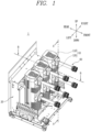
FIG. 1 is a perspective view of a vacuum circuit breaker according to an embodiment of the present disclosure. -
FIG. 2 is a side cross-sectional view of the vacuum circuit breaker ofFIG. 1 . -
FIG. 3 is a plan cross-sectional view of the vacuum circuit breaker ofFIG. 1 . -
FIG. 4 is a perspective view of an electric conduction pole included in the vacuum circuit breaker ofFIG. 1 . -
FIG. 5 is a side view of the electric conduction pole ofFIG. 4 . -
FIG. 6A is a side cross-sectional view of the electric conduction pole ofFIG. 4 . -
FIG. 6B is a perspective view for explaining the electric conduction pole ofFIG. 4 . -
FIG. 6C is a side cross-sectional view for explaining an electric conduction pole according to another embodiment of the present disclosure. -
FIG. 7 is a plan view of the electric conduction pole ofFIG. 4 . -
FIG. 8 is a plan cross-sectional view of the electric conduction pole ofFIG. 4 . -
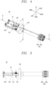
FIG. 9 is a perspective view of the temperature detection sensor included in the vacuum circuit breaker ofFIG. 1 . -
FIG. 10 is a side view of the temperature detection sensor ofFIG. 9 . -
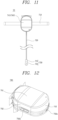
FIG. 11 is a plan view of the temperature detection sensor ofFIG. 9 . -
FIG. 12 is a perspective view of a sensor body included in the temperature detection sensor ofFIG. 9 . -
FIG. 13 is a side view of the sensor body ofFIG. 12 . -
FIG. 14 is a front view of the sensor body ofFIG. 12 . - Hereinafter, a
vacuum circuit breaker 1 according to an embodiment of the present disclosure will be described in detail with reference to the drawings. - In the following description, descriptions of some components will be omitted to help understanding of the present disclosure.
- In this specification, the same/like reference numerals are given to the same/like components even in different embodiments, and a redundant description thereof will be omitted.
- The accompanying drawings are merely used to help easily understand the technical idea of the present disclosure and it should be understood that the idea of the present disclosure is not limited by the accompanying drawings.
- A singular representation may include a plural representation unless it represents a definitely different meaning from the context.
- The terms "upper," "lower," "left," "right,", "front," and "rear" used in the following description will be understood based on a coordinate system illustrated in
FIGS. 1 and4 . - Hereinafter, referring to
FIGS. 1 to 8 , thevacuum circuit breaker 1 according to an embodiment of the present disclosure will be described. - The
vacuum circuit breaker 1 may allow or block a state of electrical connection between an external power source and a load. To do so, thevacuum circuit breaker 1 is electrically connected to the external power source and the load. In other words, the external power source and the load may be electrically connected to each other by thevacuum circuit breaker 1. - When a fixed contact point and a movable contact point of the
vacuum circuit breaker 1 are in contact with each other, the external power source may be electrically connected to the load via thevacuum circuit breaker 1. On the other hand, when a fixed contact point and a movable contact point of thevacuum circuit breaker 1 are apart from each other, a state of electrical connection between the external power source and the load is blocked. - Referring to
FIGS. 1 to 3 , thevacuum circuit breaker 1 according to an embodiment of the present disclosure includes aframe unit 10, amechanism assembly 20, alink part 30, aspring part 40, a vacuum interrupter (VI) 50, anelectric conduction pole 60, and atemperature detection sensor 70. - Hereinafter, referring to the attached drawings, a configuration of the
vacuum circuit breaker 1 according to an embodiment of the present disclosure will be described. Theframe unit 10, themechanism assembly 20, thelink part 30, thespring part 40, theVI 50, theelectric conduction pole 60, and thetemperature detection sensor 70 will be described in separate clauses. - Hereinafter, referring to
FIGS. 1 to 3 , theframe unit 10 is described. - The
frame unit 10 forms an outer appearance of thevacuum circuit breaker 1. Theframe unit 10 is a part in which thevacuum circuit breaker 1 is exposed to outside. - A space is provided in the
frame unit 10. Various components configured to operate thevacuum circuit breaker 1 may be accommodated in the space. The various components may be surrounded by theframe unit 10 not to be exposed to outside. - In the illustrated embodiment, the
mechanism assembly 20, thelink part 30, thespring part 40, theVI 50, theelectric conduction pole 60, and thetemperature detection sensor 70 are accommodated in the space inside theframe unit 10. - In the illustrated embodiment, the
frame unit 10 includes anupper frame 110 and aside frame 120. - The
upper frame 110 is arranged at one side of theframe unit 10, i.e., at an upper side in the illustrated embodiment. Theupper frame 110 is arranged to cover the space defined in theframe unit 10 from the upper side. - In the illustrated embodiment, the
upper frame 110 is provided to have a rectangular plate shape in which an extending length in an anteroposterior direction is greater than an extending length in a left-and-right direction. - Edges of the
upper frame 110 are respectively consecutive to theside frame 120. - The
upper frame 110 may be provided in plurality. The plurality ofupper frames 110 are spaced apart from each other. - The
side frame 120 forms side surfaces of theframe unit 10, i.e., a left side, a right side, a front side, or a rear side of theframe unit 10 in the illustrated embodiment. Theside frame 120 covers the space defined in theframe unit 10 from the left, right, front, and rear sides. - In the illustrated embodiment, the
side frame 120 is provided to have a column shape extending in an upward-and-downward direction. - One edge of the
side frame 120 in an extending direction is provided to be consecutive to theupper frame 110. In the illustrated embodiment, an upper edge of theside frame 120 is provided to be consecutive to theupper frame 110. - The
side frame 120 may be provided in plurality. In this case, the plurality of side frames 120 are spaced apart from each other. In the illustrated embodiment, threeside frames 120 are arranged in parallel with each other in a left-and-right direction. - An electric conduction
pole insertion opening 121 capable of accommodating theelectric conduction pole 60 is provided on an outer circumference of theside frame 120. In the illustrated embodiment, the electric conductionpole insertion opening 121 for accommodating theelectric conduction pole 60 is provided on an outer circumference surface of theside frame 120 at a front side. - The electric conduction
pole insertion opening 121 accommodates theelectric conduction pole 60 such that theelectric conduction pole 60 communicates with external and internal spaces of theside frame 120. - A space for accommodating the
electric conduction pole 60 is defined inside the electric conductionpole insertion opening 121. That is, theelectric conduction pole 60 is coupled through the electric conductionpole insertion opening 121. - The electric conduction
pole insertion opening 121 extends in a same direction as an extending direction of theelectric conduction pole 60. In the illustrated embodiment, the electric conductionpole insertion opening 121 extends in an anteroposterior direction. - The electric conduction
pole insertion opening 121 is arranged to surround theelectric conduction pole 60. That is, theelectric conduction pole 60 is surrounded by the electric conductionpole insertion opening 121. - The electric conduction
pole insertion opening 121 may be provided in plurality. A number of the electric conductionpole insertion openings 121 is identical to a number of theelectric conduction poles 60 coupled to the side frames 120. In the illustrated embodiment, three pairs of electric conductionpole insertion openings 121 are arranged in parallel with each other along a left-and-right direction. - A number of the electric conduction
pole insertion openings 121 may be determined according to a type of a power system including thevacuum circuit breaker 1 in the present disclosure. In one embodiment, thevacuum circuit breaker 1 is included in a power system using a circuit of three phases such as an R-phase, an S-phase, and a T-phase. Accordingly, three pairs of electric conductionpole insertion openings 121 are included in accordance with the three-phase circuit. - Hereinafter, referring to
FIGS. 1 to 3 , themechanism assembly 20, thelink part 30, and thespring part 40 will be described. - The
mechanism assembly 20 controls thevacuum circuit breaker 1 to operate in a closed state or a trip state. Themechanism assembly 20 is manipulated to be rotated to provide a state of electrical connection between thevacuum circuit breaker 1 and an external power source or a load, or block electrical connection therebetween. - The
mechanism assembly 20 is accommodated in the space defined inside theframe unit 10. Themechanism assembly 20 may be operated to be rotated in the space. - The
mechanism assembly 20 is connected to thelink part 30 and thespring part 40. Themechanism assembly 20 may be operated to be rotated with at least one of thelink part 30 and thespring part 40. - * As the
mechanism assembly 20 is operated, thelink part 30 may be rotated to operate thevacuum circuit breaker 1 in a closed state or trip state. - The
link part 30 is connected to themechanism assembly 20. As components of themechanism assembly 20 are rotated, thelink part 30 may be rotated along with the components. - The
link part 30 is rotatably coupled to theframe unit 10. - The
link part 30 converts linear movement of a main shaft connected to themechanism assembly 20 in a vertical direction into linear movement in a horizontal direction relative to a ground surface. - One end of the
link part 30 is connected to a distal end of the main shaft. In addition, another end of thelink part 30 is connected to thespring part 40. - As the
link part 30 is rotated, thespring part 40 is linearly moved to cause a VI fixedcontact point 510 and a VImovable contact point 520 to be in contact with or spaced apart from each other, - The
spring part 40 is connected to thelink part 30. As thelink part 30 is rotated, thespring part 40 may be linearly moved. - In addition, the
spring part 40 is connected to theVI 50. In detail, thespring part 40 is connected to the VImovable contact part 520. As thespring part 40 is moved, the VImovable contact point 520 is moved together. - Hereinafter, referring to
FIG. 2 , theVI 50 is described. - The
VI 50 is accommodated in the space defined inside theframe unit 10 to allow or block current conduction. In detail, as the VI fixedcontact point 510 and the VImovable contact point 520 are brought into contact with each other, theVI 50 allows current conduction, or as the VI fixedcontact point 510 is apart from the VImovable contact point 520, theVI 50 blocks current conduction. - The
VI 50 is connected to thespring part 40. As thespring part 40 is moved, components of theVI 50 may come in contact with each other or be spaced apart from each other. - * The
VI 50 may be provided in plurality. In the illustrated embodiment, three Vis 50 are arranged in parallel with each other along a left-and-right direction. - A number of the VIs 50 may be determined according to a type of a power system including the
vacuum circuit breaker 1 in the present disclosure. When thevacuum circuit breaker 1 is included in a power system using a circuit of three phases such as an R-phase, an S-phase, and a T-phase, three Vis 50 also may be included in accordance with the three phase circuit. - In the illustrated embodiment, the
VI 50 includes a VI fixedcontact point 510 and a VImovable contact point 520. - The VI fixed
contact point 510 is electrically connected to an external power source or a load. Thevacuum circuit breaker 1 may be electrically connected to an external power source or a load via the VI fixedcontact point 510. - The VI fixed
contact point 510 is accommodated inside theside frame 120. That is, the VI fixedcontact point 510 is surrounded by theside frame 120. - The VI fixed
contact point 510 may include a conductive material. For example, the VI fixedcontact point 510 may include copper (Cu), silver (Ag), etc. - As the VI fixed
contact point 510 is in contact with or apart from the VImovable contact point 520, an electrical connection between inside and outside of thevacuum circuit breaker 1 may be allowed or blocked. - The
VIfixed contact point 510 is not moved in the inner space of theframe unit 10. Accordingly, the VImovable contact point 520 may be brought into a contact with or spaced apart from the VI fixedcontact point 510 by moving the VImovable contact point 520. - The VI fixed
contact point 510 may be provided in plurality. In the illustrated embodiment, three VI fixed contact points 510 are arranged in parallel with each other in a left-and-right direction. - The VI
movable contact point 520 is electrically connected to an external power source or a load. In addition, the VImovable contact point 520 is electrically connected to or disconnected from the VI fixedcontact point 510. - The VI
movable contact point 520 is accommodated inside theside frame 120. That is, the VI fixedcontact point 510 is surrounded by theside frame 120. - The VI
movable contact point 520 may include a conductive material. For example, the VImovable contact point 520 may include copper (Cu), silver (Ag), etc. - The VI
movable contact point 520 may be moved to be brought into contact with or spaced apart from the VI fixedcontact point 510. In detail, the VImovable contact point 520 may be moved in a direction toward or away from the VI fixedcontact point 510. - When the VI
movable contact point 520 is moved in a direction toward the VI fixedcontact point 510, the VImovable contact point 520 and the VI fixedcontact point 510 come in contact with each other. In this case, an electrical connection between the external power source and the load may be allowed. - In addition, when the VI
movable contact point 520 is moved in a direction away from the VI fixedcontact point 510, the VImovable contact point 520 and the VI fixedcontact point 510 are spaced apart from each other. In this case, an electrical connection between the external power source and the load is blocked. - The VI
movable contact point 520 may be provided in plurality. In the illustrated embodiment, three VImovable contact point 520 are arranged in parallel with each other in a left-and-right direction. - Hereinafter, referring to
FIGS. 1 to 8 , theelectric conduction pole 60 is described. - The
electric conduction pole 60 electrically connects theVI 50 to an external power source or a load. To do so, theelectric conduction pole 60 is electrically connected to theVI 50 and the external power source or the load. - The
electric conduction pole 60 is coupled through one side of theside frame 120. In detail, theelectric conduction pole 60 is coupled through the electric conductionpole insertion opening 121 in theside frame 120. - The
electric conduction pole 60 may be provided in plurality. In the illustrated embodiment, three pairs ofelectric conduction poles 60 are arranged in parallel with each other in a left-and-right direction. - A number of the
electric conduction poles 60 may be determined according to a type of a power system including thevacuum circuit breaker 1 in the present disclosure. In one embodiment, thevacuum circuit breaker 1 is included in a power system using a circuit of three phases such as an R-phase, an S-phase, and a T-phase. Accordingly, three pairs ofelectric conduction poles 60 are included in accordance with the three-phase circuit. - In the illustrated embodiment, the
electric conduction pole 60 includes ahousing part 610, aplate part 620, an electricconduction pole terminal 630, acoupling member 640, and atulip contactor 650. - The
housing part 610 forms an outer appearance of theelectric conduction pole 60. Thehousing part 610 is a part in which theelectric conduction pole 60 is exposed to outside. - The
housing part 610 is provided to have a cylindrical shape extending in one direction. In the illustrated embodiment, thehousing part 610 is provided to have a cylindrical shape extending in an anteroposterior direction. - A hollow hole is provided in the
housing part 610. The hollow hole may accommodate the electricconduction pole terminal 630 therein. That is, the electricconduction pole terminal 630 is surrounded by thehousing part 610. - The
housing part 610 may be provided to include an insulating material. For example, thehousing part 610 may be provided to include a synthetic resin material. Thus, an arbitrary electrical connection between inside and outside of theelectric conduction pole 60 may be prevented. - The
plate part 620 is a part in which theelectric conduction pole 60 is directly coupled to theVI 50. In detail, theplate part 620 is electrically coupled to theVI 50. - The electric
conduction pole terminal 630 is coupled to one end of theplate part 620. In the illustrated embodiment, the electricconduction pole terminal 630 is coupled to one end of theplate part 620 at a front side. - The
plate part 620 is provided to have a plate shape. In the illustrated embodiment, theplate part 620 is provided to have a rectangular plate shape in which an extending length in an anteroposterior direction is greater than an extending length in a left-and-right direction. - The
plate part 620 may be provided to include a conductive material. For example, theplate part 620 may include copper (Cu), silver (Ag), etc. - In the illustrated embodiment, the
plate part 620 includes a band throughhole 621 and a fixingclamp 622. - The band through
hole 621 may be provided in one side of theplate part 620. In the illustrated embodiment, the band throughhole 621 is provided in both left and right sides of theplate part 620. - The band through
hole 621 allows thetemperature detection sensor 70 to be securely coupled to theelectric conduction pole 60. - The
temperature detection sensor 70 is coupled through the band throughhole 621. In detail, the fixingband 710 of thetemperature detection sensor 70 is coupled through the band throughhole 621. - In the illustrated embodiment, the band through
hole 621 is provided such that a polygonal cross-section extends. However, the band throughhole 621 is not limited to the illustrated shape, and may be provided in various shapes. For example, the band throughhole 621 may be provided such that an oval cross-section extends. - The fixing
clamp 622 prevents arbitrary deviation of thetemperature detection sensor 70. In detail, the fixingclamp 622 fixes theconnection line 720 to theplate part 620 to prevent arbitrary deviation of theconnection line 720 of thetemperature detection sensor 70. - To do so, the fixing
claim 622 surrounds a part of theconnection line 720 to be coupled to theplate part 620. That is, the fixingclamp 622 and theplate part 620 are coupled to each other to have theconnection line 720 therebetween. - The electric
conduction pole terminal 630 is coupled to one end of theplate part 620. - The electric
conduction pole terminal 630 electrically connects theplate part 620 to thetulip contactor 650. To do so, the electricconduction pole terminal 630 is electrically coupled respectively to theplate part 620 and thetulip contactor 650. - The electric
conduction pole terminal 630 is accommodated in the space defined inside thehousing part 610. That is, the electricconduction pole terminal 630 is surrounded by thehousing part 610. - In the illustrated embodiment, the electric
conduction pole terminal 630 is provided to have a cylindrical shape extending in an anteroposterior direction. However, the electricconduction pole terminal 630 is not limited to the illustrated shape, and may be provided in various shapes. For example, the electricconduction pole terminal 630 may have a polyprism shape. - In the illustrated embodiment, a
terminal hole 631 is provided in the electricconduction pole terminal 630. - Some components of the
temperature detection sensor 70 may be accommodated in theterminal hole 631. In the illustrated embodiment, theterminal hole 631 accommodates theconnection line 720 and a fixingterminal 730 each included in thetemperature detection sensor 70. A detailed description thereof will be given later. - The electric
conduction pole terminal 630 is coupled to thetulip contactor 650 by thecoupling member 640. - The
coupling member 640 passes through the electricconduction pole terminal 630 and thetulip contactor 650 to secure the coupling therebetween. - The
coupling member 640 is not limited to the illustrated shape, and may be provided in various shapes. In one embodiment, thecoupling member 640 may be coupled to the electricconduction pole terminal 630 and thetulip contactor 650 by using a bolt-nut coupling method. - The
coupling member 640 may be provided to include a highly rigid material. For example, thecoupling member 640 may be provided to include a metal material. - The
tulip contactor 650 is a part in which thevacuum circuit breaker 1 is in direct contact with a terminal of the external power source or the load. - In the illustrated embodiment, the
tulip contactor 650 includes a fixingring 651, acontactor plate 652, a saw-toothed ring 653, and atulip finger 654. - The fixing
ring 651 increases contact force between thetulip contactor 650 and the terminal of the external power source or the load. - The fixing
ring 651 is positioned to surround an outer circumferential surface of thetulip finger 654. In detail, the fixingring 651 is positioned in a coupling groove in the fixingring 651 of thetulip finger 654. - The fixing
ring 651 is provided to have a ring shape. In the illustrated embodiment, a center of the fixingring 651 is provided to be identical to a center of thetulip finger 654. - The fixing
ring 651 supports thetulip finger 654 at a radially outer side and prevents arbitrary deviation of thetulip finger 654. - In one embodiment, a diameter of the fixing
ring 651 is provided to be smaller than an outer diameter of thetulip finger 654. Accordingly, contact force between thetulip finger 654 and the external terminal may increase. - The fixing
ring 651 may be provided in plurality. In the illustrated embodiment, four fixingrings 651 are arranged in parallel with each other along an anteroposterior direction. - The
contactor plate 652 and the saw-toothed ring 653 are positioned at a radially inner side of the fixingring 651 and thetulip finger 654. - The
contact plate 652 is positioned to meet the terminal of the external power source or the load. - The
contactor plate 652 is electrically connected to the electricconduction pole terminal 630 to electrically connect the external power source or the load to the electricconduction pole terminal 630. - The
contactor plate 652 may have a plate shape. In the illustrated embodiment, thecontactor plate 652 may be formed in a disk shape. - The
contactor plate 652 may be provided to include a conductive material. For example, thecontactor plate 652 may include copper (Cu), silver (Ag), etc. - The saw-
toothed ring 653 prevents twisting or movement of thetulip finger 654. - * The fixing
ring 653 is positioned at a radially outer side of thetulip finger 654 to support thetulip finger 654 at the radially outer side. - The saw-
toothed ring 653 is provided to have a disk shape in which a plurality of saw teeth are provided on an outer circumferential surface. In one embodiment, a number of the saw teeth is identical to a number oftulip fingers 654. - The saw-
toothed ring 653 may be provided to include a highly rigid material. For example, the saw-toothed ring 653 may include a metal material. - The saw-
toothed ring 653 may be provided in plurality. In one embodiment, two saw-toothed rings 653 may be provided. - The
tulip finger 654 increases contact force between the terminal of the external power source or the load and thevacuum circuit breaker 1. - The
tulip finger 654 may be provided in plurality. The plurality oftulip fingers 654 are arranged along a circumferential direction of a concentric circle. In the illustrated embodiment, the plurality oftulip fingers 654 are all provided to have a same shape. - The
tulip finger 654 is provided to have a plate shape extending in one direction. In the illustrated embodiment, thetulip finger 654 extends in an anteroposterior direction. - The fixing
ring 651 is coupled to a radially outer side of thetulip finger 654. In addition, thecontactor plate 652 and the saw-toothed ring 653 are coupled to each other at a radially inner side of thetulip finger 654. In summary, the radially outer side of thetulip finger 654 is supported by the fixingring 651, and the radially inner side of thetulip finger 654 is supported by thecontactor plate 652 and the saw-toothed ring 653. - Hereinafter, referring to
FIGS. 4 to 14 , thetemperature detection sensor 70 according to an embodiment of the present disclosure will be described. - The
temperature detection sensor 70 measures and monitors temperature of a specific point of thevacuum circuit breaker 1. - The
temperature detection sensor 70 is accommodated in the space defined inside theframe unit 10. - The
temperature detection sensor 70 is arranged adjacent to theelectric conduction pole 60. In detail, thetemperature detection sensor 70 is arranged adjacent to theplate part 620 of theelectric conduction pole 60. In the illustrated embodiment, thetemperature detection sensor 70 is arranged adjacent to an upper side surface of theplate part 620. - The
temperature detection sensor 70 may be coupled to theelectric conduction pole 60 to measure temperature of a specific point of theelectric conduction pole 60. - In the illustrated embodiment, the
temperature detection sensor 70 includes the fixingband 710, theconnection line 720, the fixingterminal 730, and asensor body 740. - The fixing
band 710 fixes thesensor body 740 to theelectric conduction pole 60. In detail, the fixingband 710 fixes thesensor body 740 to thecoupling member 620 of theelectric conduction pole 60. - The fixing
band 710 is arranged to surround theplate part 620. In this case, the fixingband 710 may pass through the band throughhole 621 in theplate part 620. Accordingly, it is desirable to provide a cross-sectional area of the fixingband 710 to be smaller than that of the band throughhole 621. - In addition, the fixing
band 710 may be coupled through thesensor body 740. In detail, the fixingband 710 may be coupled through aband insertion opening 742a in thesensor body 740. - In the illustrated embodiment, the fixing
band 710 may be formed in a ring shape. However, the fixingband 710 is not limited to the illustrated shape, and may be provided in various shapes. - In one embodiment, the fixing
band 710 may be provided to include a high elastic material. For example, the fixingband 710 may include a synthetic rubber material. - The
connection line 720 is coupled respectively to the fixingterminal 730 and thesensor body 740 to transmit temperature collected from the fixingterminal 730 to thesensor body 740. To do so, theconnection line 720 is electrically connected respectively to the fixingterminal 730 and thesensor body 740. - In one embodiment, the
connection line 720 is connected to an input unit in thesensor body 740. The input unit collects temperature data via theconnection line 720 and transmit the temperature data to a data processing unit. - The
connection line 720 is provided as a line extending in one direction. In the illustrated embodiment, theconnection line 720 extends in an anteroposterior direction. - In one embodiment, the
connection line 720 is accommodated in theterminal hole 631. That is, theconnection line 720 extends to pass through theterminal hole 631. - The
connection line 720 may be fixed to theplate part 620 of theelectric conduction pole 60 by the fixingclamp 622. That is, arbitration deviation of theconnection line 720 may be prevented by the fixingclamp 622. - In one embodiment, a part of the
connection line 720 may be accommodated in an inner space of thesensor body 740. In the embodiment, theconnection line 720 passes through a connectionline coupling opening 743a to be coupled through thesensor body 740. - The
connection line 720 may be provided in plurality. For example, twoconnection lines 720 may be provided. In this case, therespective connection lines 720 are spaced apart from each other and may measure temperatures of different points. - The fixing
terminal 730 is a part at which thetemperature detection sensor 70 directly measures temperature. - The fixing
terminal 730 is fixed to be in contact with a specific point of which temperature is to be measured. In the illustrated embodiment, the fixingterminal 730 may be in contact with thetulip finger 650 to measure temperature of thetulip finger 650. - In one embodiment, the fixing
terminal 730 may be accommodated in theterminal hole 631. - The fixing
terminal 730 is coupled to theconnection line 720 and transmits temperature data to thesensor body 740 via theconnection line 720. - The fixing
terminal 730 may be provided in plurality. In this case, theconnection line 720 is coupled to each of the fixingterminals 730. - In the illustrated embodiment, the fixing
terminal 730 includes a connectionline coupling part 731 and atarget contact part 732. - The connection
line coupling part 731 is coupled respectively to theconnection line 720 and thetarget contact part 732 to electrically connect theconnection line 720 to thetarget contact part 732. - The connection
line coupling part 731 is arranged to surround one end of theconnection line 720. - In the illustrated embodiment, the connection
line coupling part 731 is provided to have a cylindrical shape having a hollow hole therein. However, the connectionline coupling part 731 is not limited to the illustrated shape, and may be provided in various shapes. For example, the connectionline coupling part 731 may have a polyprism shape. - The
target contact part 732 is coupled to one side of the connectionline coupling part 731 arranged in a position opposite to theconnection line 720. - The
temperature measurement part 732 is a part at which thetemperature detection sensor 70 directly measures temperature. - The
target contact part 732 is arranged adjacent to a specific point of which temperature is to be measured. - As illustrated in
FIGS. 6A and 6B , thetarget contact part 732 may be fixed to thecontactor plate 652 of thetulip contactor 650 by abolt 641. - As illustrated in
FIG. 6C , thetarget contact part 732 may be arranged adjacent to thecontactor plate 652 of thetulip contactor 650. Thetarget contact part 732 may be fixed by thebolt 641 to be adjacent to thecontactor plate 652 in the electricconduction pole terminal 630. The connectionline coupling part 731 is coupled to one side of thetarget contact part 732 arranged in a position opposite to the specific point. - The
sensor body 740 processes temperature data collected from thetarget contact part 732 and transmits the temperature data to outside of thevacuum circuit breaker 1. - The
sensor body 740 is arranged adjacent to thetulip contactor 620 of theelectric conduction pole 60. In the illustrated embodiment, thesensor body 740 is arranged adjacent to an upper side surface of theplate part 620. - In addition, the
sensor body 740 is coupled to theplate part 620. - In one embodiment, the
sensor body 740 is coupled to theplate part 620 by the fixingband 710. The fixingband 710 passes respectively through thesensor body 740 and theplate part 620, and tightly couples thesensor body 740 to theplate part 620. - In another embodiment, a protruding part extending toward the
plate part 620 is provided at one side of thesensor body 740. In addition, a recessed part is provided on one surface of theplate part 620 facing thesensor body 740. The protruding part may be coupled into the recessed part. In this case, the protruding part is provided to have a shape corresponding to the recessed part. - The
connection line 720 is coupled to one side of thesensor body 740. In the illustrated embodiment, theconnection line 720 is coupled to a front side of thesensor body 740. - A space for accommodating various components therein is defined in the
sensor body 740. A power unit, an input unit, a data processing unit, and a communication unit may be included in the space. - The power unit provides a power source configured to operate the
temperature detection sensor 70. - The input unit is coupled to the
connection line 720 to collect temperature data transmitted via the fixingterminal 730 and theconnection line 720, and transmit the temperature data to the data processing unit. - The data processing unit arranges data transmitted from the input unit, and then, transmits the data to the communication unit.
- The communication unit transmits the data transmitted from the data processing unit to outside of the
vacuum circuit breaker 1. A user may check the data transmitted by the communication unit to measure and monitor temperature of thevacuum circuit breaker 1. - In the illustrated embodiment, the
sensor body 740 is divided into a bodyupper surface portion 741, a bodyside surface portion 742, and a bodyfront surface portion 743. - The body
upper surface portion 741, the bodyside surface portion 742, and the bodyfront surface portion 743 form boundaries at an upper side, left and right sides and a front side of thesensor body 740, respectively. - The body
side surface portion 742 extends from each end of the left and right sides of the bodyfront surface portion 741 toward a lower side. That is, the bodyside surface portion 742 is consecutive to a left or right-side end of the bodyupper surface portion 741. - A
band insertion opening 742a is provided in the bodyside surface portion 742. - The
band insertion opening 742a is a space through which thefixing band 710 is coupled. To do so, it is desirable to provide a cross-sectional area of theband insertion opening 742a to be greater than that of the fixingband 710. - In the illustrated embodiment, the
band insertion opening 742a is provided such that an oval cross-section extends. However, theband insertion opening 742a is not limited to the illustrated shape, and may be provided in various shapes. For example, theband insertion opening 742a may be provided such that a polygonal cross-section extends. - The body
front surface portion 743 extends from an end of the front side of the bodyupper surface portion 741 toward a lower side. That is, the bodyfront surface portion 743 is consecutive to the end of the front side of the bodyfront surface portion 741. - The connection
line coupling opening 743a is provided in the bodyfront surface portion 743. - The connection
line coupling opening 743a is a space through which a connection opening is coupled. To do so, it is desirable to provide a cross-sectional area of the connectionline coupling opening 743a to be greater than that of theconnection line 720. - In the illustrated embodiment, the connection
line coupling opening 743a is provided such that a round cross-section extends. However, the connectionline coupling opening 743a is not limited to the illustrated shape, and may be provided in various shapes. For example, the connectionline coupling opening 743a may be provided such that a polygonal cross-section extends. - A single or a plurality of connection
line coupling openings 743a may be provided. In this case, a number of the connectionline coupling openings 743a is provided to be identical to a number of the connection lines 720. - Although the foregoing description has been given with reference to the preferred embodiments of the present disclosure, the present disclosure is not limited to the configuration of the above-described embodiments.
- In addition, it should be understood that the present disclosure can be variously modified and changed by those skilled in the art to which the present disclosure pertains without departing from the spirit and scope of the present disclosure described in the claims below.
- Furthermore, all or part of those embodiments may be selectively combined so that various modifications can be made.
Claims (14)
- A vacuum circuit breaker comprising:an electric conduction pole electrically connected to an external power source or a load; anda temperature detection sensor disposed adjacent to the electric conduction pole,wherein the electric conduction pole comprises:a plate part provided to have a plate shape; andan electric conduction pole terminal provided to have a column shape extending in one direction and having one end coupled to the plate part, andthe temperature detection sensor comprises:a sensor body arranged adjacent to one side of the plate part and having an input unit accommodated therein;a fixing terminal which is in contact with a specific point of the electric conduction pole and configured to measure temperature of the specific point; anda connection line positioned in the electric conduction pole terminal, and having one end coupled to the sensor body and another end coupled to the fixing terminal.
- The vacuum circuit breaker of claim 1, wherein the electric conduction pole comprises a tulip contactor in direct contact with a terminal of the external power source or the load, and
the specific point is positioned in a part of the tulip contactor. - The vacuum circuit breaker of claim 1, wherein the fixing terminal comprises:a connection line coupling part surrounding the another end of the connection line; anda target contact part being in contact with the specific point and coupled to the connection line coupling part.
- The vacuum circuit breaker of claim 3, wherein the electric conduction pole comprises a tulip contactor in direct contact with a terminal of the external power source or the load, and
the target contact part is in contact with a part of the tulip contactor. - The vacuum circuit breaker of claim 1, wherein the temperature detection sensor comprises a fixing band coupled to the sensor body and arranged to surround the plate part.
- The vacuum circuit breaker of claim 5, wherein the fixing band passes through a band insertion opening provided in the sensor body, and is coupled to the sensor body.
- The vacuum circuit breaker of claim 5, wherein the fixing band passes through a band through hole provided in the plate part, and is coupled to the plate part.
- The vacuum circuit breaker of claim 1, wherein a protruding part extending toward the plate part is provided at one side of the sensor body, and a recess part is provided on one surface of the plate part facing the sensor body, the recess part having a shape corresponding to the protruding part and the protruding part being inserted through the recess part.
- The vacuum circuit breaker of claim 1, wherein the electric conduction pole comprises a fixing clamp surrounding a part of the connection line and coupled to one surface of the plate part facing the connection line to have the connection line therebetween.
- The vacuum circuit breaker of claim 1, wherein the connection line extends or retracts to correspond to a distance between the sensor body and the fixing terminal.
- The vacuum circuit breaker of claim 1, wherein the fixing terminal is provided in plurality, and the plurality of fixing terminals are coupled to different connection lines, respectively.
- The vacuum circuit breaker of claim 1, wherein the input unit collects temperature data from the fixing terminal, and
the temperature detection sensor comprises:a data processing unit configured to receive the temperature data from the input unit and process the temperature data; anda communication unit configured to transmit, to outside, the temperature data arranged by the data processing unit. - The vacuum circuit breaker of claim 1, wherein a terminal hole is provided in the electric conduction pole terminal.
- The vacuum circuit breaker of claim 13, wherein the fixing terminal is accommodated in the terminal hole and coupled to one end of the electric conduction pole terminal.
Applications Claiming Priority (2)
| Application Number | Priority Date | Filing Date | Title |
|---|---|---|---|
| KR1020210042100A KR102501590B1 (en) | 2021-03-31 | 2021-03-31 | Vacuum circuit breaker |
| PCT/KR2022/000849 WO2022211235A1 (en) | 2021-03-31 | 2022-01-17 | Vacuum circuit breaker |
Publications (2)
| Publication Number | Publication Date |
|---|---|
| EP4318525A1 true EP4318525A1 (en) | 2024-02-07 |
| EP4318525A4 EP4318525A4 (en) | 2025-02-12 |
Family
ID=83455315
Family Applications (1)
| Application Number | Title | Priority Date | Filing Date |
|---|---|---|---|
| EP22781356.5A Pending EP4318525A4 (en) | 2021-03-31 | 2022-01-17 | Vacuum circuit breaker |
Country Status (6)
| Country | Link |
|---|---|
| US (1) | US20240186085A1 (en) |
| EP (1) | EP4318525A4 (en) |
| JP (1) | JP7503716B2 (en) |
| KR (1) | KR102501590B1 (en) |
| CN (1) | CN117157724A (en) |
| WO (1) | WO2022211235A1 (en) |
Family Cites Families (20)
| Publication number | Priority date | Publication date | Assignee | Title |
|---|---|---|---|---|
| US5929410A (en) * | 1998-01-26 | 1999-07-27 | Lg Industrial Systems Co., Ltd. | Terminal structure for vacuum circuit breaker |
| US7696447B2 (en) * | 2007-06-01 | 2010-04-13 | Eaton Corporation | Electrical switching apparatus and stored energy assembly therefor |
| CN202255681U (en) * | 2011-09-22 | 2012-05-30 | 常州森隆电力科技有限公司 | On-line temperature monitoring device for circuit breaker |
| CN202816780U (en) * | 2012-09-11 | 2013-03-20 | 中骏电气(厦门)有限公司 | Integrated environmentally friendly solid-sealed polar pole |
| KR20140044206A (en) | 2012-10-04 | 2014-04-14 | 현대중공업 주식회사 | Gas insulated switchgear |
| CN203274957U (en) * | 2013-04-28 | 2013-11-06 | Abb技术有限公司 | Package type wireless temperature measuring device for medium voltage circuit breaker |
| KR101564991B1 (en) * | 2013-11-18 | 2015-11-03 | 엘에스산전 주식회사 | Main Circuit Part of Vacuum Circuit Breaker with Self Powered Temperature Sensor Assembly |
| KR101670304B1 (en) * | 2014-10-23 | 2016-10-31 | 엘에스산전 주식회사 | Vacuum Circuit Breaker with Temperature Monitoring |
| US10533978B2 (en) * | 2015-08-13 | 2020-01-14 | Eaton Intelligent Power Limited | Vibration sensor assembly for prognostic and diagnostic health assessment of a power circuit breaker's power transmission and distribution system in real time |
| EP3270395B1 (en) * | 2016-07-15 | 2021-01-27 | ABB Schweiz AG | Vibration-limiting device for an apparatus comprising a switchgear and a switching device, such as a circuit breaker, and apparatus comprising said vibration-limiting device |
| CN206432194U (en) | 2016-09-01 | 2017-08-22 | 希格玛电气(珠海)有限公司 | A kind of intelligent switchgear assembly of pole-mounted circuit breaker |
| US10249459B2 (en) * | 2016-09-19 | 2019-04-02 | Eaton Intelligent Power Limited | Advanced cooling system for electrical equipment |
| KR101773306B1 (en) | 2016-12-19 | 2017-08-31 | 신승현 | Apparatus for sensing the temperature of a switch board |
| JP6919390B2 (en) | 2017-07-24 | 2021-08-18 | 富士電機機器制御株式会社 | Drawer type vacuum circuit breaker |
| CN208296994U (en) | 2018-02-13 | 2018-12-28 | Abb瑞士股份有限公司 | A kind of low-tension switch cabinet system for detecting temperature |
| CN208805294U (en) * | 2018-09-25 | 2019-04-30 | Abb 瑞士股份有限公司 | Non-invasive temperature measuring device for medium voltage circuit breaker and medium voltage circuit breaker |
| CN208738127U (en) * | 2018-10-22 | 2019-04-12 | 厦门威尔圣电气股份有限公司 | A kind of indoor vacuum circuit breaker of wireless temperature measurement |
| CN209266992U (en) * | 2018-12-14 | 2019-08-16 | 湖南长高成套电器有限公司 | Intelligent switchboard system |
| CN210073704U (en) | 2019-06-04 | 2020-02-14 | 广州五合智能电气有限公司 | Vacuum circuit breaker for railway |
| US10741338B1 (en) * | 2019-08-09 | 2020-08-11 | Xj Electric Co., Ltd | Contact device of handcart circuit breaker and handcart circuit breaker |
-
2021
- 2021-03-31 KR KR1020210042100A patent/KR102501590B1/en active Active
-
2022
- 2022-01-17 EP EP22781356.5A patent/EP4318525A4/en active Pending
- 2022-01-17 US US18/285,051 patent/US20240186085A1/en active Pending
- 2022-01-17 CN CN202280026773.XA patent/CN117157724A/en active Pending
- 2022-01-17 JP JP2023544480A patent/JP7503716B2/en active Active
- 2022-01-17 WO PCT/KR2022/000849 patent/WO2022211235A1/en not_active Ceased
Also Published As
| Publication number | Publication date |
|---|---|
| KR20220135863A (en) | 2022-10-07 |
| JP7503716B2 (en) | 2024-06-20 |
| JP2024507444A (en) | 2024-02-20 |
| EP4318525A4 (en) | 2025-02-12 |
| WO2022211235A1 (en) | 2022-10-06 |
| KR102501590B1 (en) | 2023-02-21 |
| US20240186085A1 (en) | 2024-06-06 |
| CN117157724A (en) | 2023-12-01 |
Similar Documents
| Publication | Publication Date | Title |
|---|---|---|
| EP3062403B1 (en) | Gas-insulated switchgear | |
| CA3162438C (en) | Electrical system, electrical switching apparatus and guard assembly therefor | |
| US12244122B2 (en) | Arc mitigation apparatus and systems for panelboard applications | |
| US12381053B2 (en) | Vacuum circuit breaker | |
| EP4318525A1 (en) | Vacuum circuit breaker | |
| KR102674084B1 (en) | Vacuum circuit breaker | |
| CN109564841B (en) | Voltage tap system for fuse box base, fuse box base and measurement module incorporating the system | |
| KR101104145B1 (en) | Phase-shielded insulated compact load switch with integrated detector and arrester | |
| KR102674082B1 (en) | Vacuum circuit breaker | |
| EP4339991A1 (en) | Fuse-switch-disconnector assembly | |
| US12620541B2 (en) | Insulating-material housing and compact circuit breaker | |
| US20240112873A1 (en) | Insulating-material housing and compact circuit breaker | |
| US11257648B2 (en) | Electronic trip device for molded case circuit breaker | |
| CN117239549A (en) | Intelligent switch cabinet drawer | |
| KR20240142356A (en) | Gas insulated switchgear | |
| EP1705767A1 (en) | Combined disconnector-earthing switch device | |
| CN119698681A (en) | Multi-pole rail-mounted device with modular construction | |
| JP2008130281A (en) | Short circuit jig and test plug | |
| KR100423887B1 (en) | Receptacle | |
| HK1225521A1 (en) | Gas-insulated switchgear | |
| HK1225521B (en) | Gas-insulated switchgear | |
| CA2278831A1 (en) | Standard sized apparatus for detecting arc faults and ground faults in multiwire branch electric power circuits | |
| JPS63209411A (en) | Gas insulated switchgear |
Legal Events
| Date | Code | Title | Description |
|---|---|---|---|
| STAA | Information on the status of an ep patent application or granted ep patent |
Free format text: STATUS: THE INTERNATIONAL PUBLICATION HAS BEEN MADE |
|
| PUAI | Public reference made under article 153(3) epc to a published international application that has entered the european phase |
Free format text: ORIGINAL CODE: 0009012 |
|
| STAA | Information on the status of an ep patent application or granted ep patent |
Free format text: STATUS: REQUEST FOR EXAMINATION WAS MADE |
|
| 17P | Request for examination filed |
Effective date: 20230703 |
|
| AK | Designated contracting states |
Kind code of ref document: A1 Designated state(s): AL AT BE BG CH CY CZ DE DK EE ES FI FR GB GR HR HU IE IS IT LI LT LU LV MC MK MT NL NO PL PT RO RS SE SI SK SM TR |
|
| DAV | Request for validation of the european patent (deleted) | ||
| DAX | Request for extension of the european patent (deleted) | ||
| A4 | Supplementary search report drawn up and despatched |
Effective date: 20250113 |
|
| RIC1 | Information provided on ipc code assigned before grant |
Ipc: H02B 11/10 20060101ALN20250107BHEP Ipc: H01H 11/00 20060101ALI20250107BHEP Ipc: H02B 11/12 20060101ALI20250107BHEP Ipc: G01K 1/14 20210101ALI20250107BHEP Ipc: H01H 33/666 20060101ALI20250107BHEP Ipc: H01H 33/66 20060101AFI20250107BHEP |